Embed Size (px)
Citation preview
Intel® RealSense™ Depth Module D400 Series Custom Calibration
Revision 1.1.0
January 2018
2
INFORMATION IN THIS DOCUMENT IS PROVIDED IN CONNECTION WITH INTEL PRODUCTS. NO LICENSE, EXPRESS OR IMPLIED, BY ESTOPPEL
OR OTHERWISE, TO ANY INTELLECTUAL PROPERTY RIGHTS IS GRANTED BY THIS DOCUMENT. EXCEPT AS PROVIDED IN INTEL'S TERMS AND
CONDITIONS OF SALE FOR SUCH PRODUCTS, INTEL ASSUMES NO LIABILITY WHATSOEVER AND INTEL DISCLAIMS ANY EXPRESS OR IMPLIED
WARRANTY, RELATING TO SALE AND/OR USE OF INTEL PRODUCTS INCLUDING LIABILITY OR WARRANTIES RELATING TO FITNESS FOR A
PARTICULAR PURPOSE, MERCHANTABILITY, OR INFRINGEMENT OF ANY PATENT, COPYRIGHT OR OTHER INTELLECTUAL PROPERTY RIGHT.
A "Mission Critical Application" is any application in which failure of the Intel Product could result, directly or indirectly, in personal injury or death.
SHOULD YOU PURCHASE OR USE INTEL'S PRODUCTS FOR ANY SUCH MISSION CRITICAL APPLICATION, YOU SHALL INDEMNIFY AND HOLD
INTEL AND ITS SUBSIDIARIES, SUBCONTRACTORS AND AFFILIATES, AND THE DIRECTORS, OFFICERS, AND EMPLOYEES OF EACH, HARMLESS
AGAINST ALL CLAIMS COSTS, DAMAGES, AND EXPENSES AND REASONABLE ATTORNEYS' FEES ARISING OUT OF, DIRECTLY OR INDIRECTLY,
ANY CLAIM OF PRODUCT LIABILITY, PERSONAL INJURY, OR DEATH ARISING IN ANY WAY OUT OF SUCH MISSION CRITICAL APPLICATION,
WHETHER OR NOT INTEL OR ITS SUBCONTRACTOR WAS NEGLIGENT IN THE DESIGN, MANUFACTURE, OR WARNING OF THE INTEL PRODUCT
OR ANY OF ITS PARTS.
Intel may make changes to specifications and product descriptions at any time, without notice. Designers must not rely on the absence or
characteristics of any features or instructions marked "reserved" or "undefined". Intel reserves these for future definition and shall have no
responsibility whatsoever for conflicts or incompatibilities arising from future changes to them. The information here is subject to change without
notice. Do not finalize a design with this information.
The products described in this document may contain design defects or errors known as errata which may cause the product to deviate from
published specifications. Current characterized errata are available on request.
Contact your local Intel sales office or your distributor to obtain the latest specifications and before placing your product order.
Copies of documents which have an order number and are referenced in this document, or other Intel literature, may be obtained by calling 1-
800-548-4725, or go to: http://www.intel.com/design/literature.htm.
Code names featured are used internally within Intel to identify products that are in development and not yet publicly announced for release.
Customers, licensees and other third parties are not authorized by Intel to use code names in advertising, promotion or marketing of any product
or services and any such use of Intel's internal code names is at the sole risk of the user.
Intel and the Intel logo are trademarks of Intel Corporation in the U.S. and other countries.
*Other names and brands may be claimed as the property of others.
Copyright © 2018, Intel Corporation. All rights reserved.
3
Contents
1 Introduction ....................................................................................................... 8
1.1 Purpose and Scope of This Document ........................................................ 8 1.2 Organization .......................................................................................... 8
2 Overview .......................................................................................................... 9
2.1 Calibration API and Calibration Data Read/Write/Restore ............................. 9 2.2 Calibration Parameters .......................................................................... 10 2.3 Frame Formats Used in Custom Calibration .............................................. 11 2.4 Frame Sync .......................................................................................... 11 2.5 Accuracy .............................................................................................. 11
3 Setup ............................................................................................................. 13
3.1 Hardware ............................................................................................. 13 3.1.1 Device .................................................................................... 14 3.1.2 Target .................................................................................... 14 3.1.3 Tripod .................................................................................... 15 3.1.4 USB ....................................................................................... 17 3.1.5 PC ......................................................................................... 17
3.2 Software .............................................................................................. 17 3.2.1 Custom Calibration Sample Application ....................................... 17 3.2.2 Intel® RealSense™ Calibration Tool and API ............................... 18 3.2.3 Intel® RealSense™ SDK ........................................................... 19 3.2.4 OpenCV 3.3.0 ......................................................................... 19 3.2.5 Glut Library ............................................................................ 20
4 Calibrating Device with Custom Calibration Sample Application.............................. 21
4.1 Process Overview .................................................................................. 21 4.2 Connect Device to Computer .................................................................. 21 4.3 Running Custom Calibration Sample Application ....................................... 21
4.3.1 Starting Application ................................................................. 21 4.3.2 Capturing Images from 6 Viewpoints .......................................... 22
4.4 Calibration Result .................................................................................. 35 4.5 Updating Results to Device ..................................................................... 37
4.5.1 Depth Quality Check before Updating Calibration ......................... 38 4.5.2 Writing Optimized Calibration to Device ...................................... 38 4.5.3 Depth Quality Check after Updating Calibration ........................... 40
5 Developing Custom Calibration Application .......................................................... 42
5.1 Sample Application Source Code and Compile ........................................... 42 5.2 Calibration Mode Camera Configuration ................................................... 44
5.2.1 Emitter ................................................................................... 44 5.2.2 Auto Exposure ......................................................................... 44 5.2.3 Streaming Resolution and Format .............................................. 45 5.2.4 Image Captures ....................................................................... 45 5.2.5 Demosaic Left/Right Images for ASR / PSR SKUs ......................... 45
5.3 Detecting the Chessboard in an Image with OpenCV ................................. 45

4
5.4 Calculating Depth Camera Calibration with OpenCV ................................... 46 5.5 Calculating RGB Camera Calibration with OpenCV ..................................... 47 5.6 Calculating RGB Camera Calibration Extrinsics with OpenCV ....................... 47 5.7 Writing Calibration Parameters ............................................................... 48
5
Tables Table 2-1. Frame Formats Used in Custom Calibration .......................................... 11 Table 3-1. Intel® RealSense™ Calibration API Resources ..................................... 18 Table 3-2. Intel® RealSense™ SDK Resources .................................................... 19 Table 3-3. OpenCV 3.3.0 Resources ................................................................... 20 Table 3-4. OpenCV 3.3.0 Libraries Required for the Example ................................. 20
6
List of Figures
Figure 2-1 Software Stack with Dynamic Calibration API and Calibration Apps ........... 9 Figure 3-1 Hardware Setup ............................................................................... 13 Figure 3-2 D415 Device .................................................................................... 14 Figure 3-3 8x7 60x60 mm Checker Calibration Target .......................................... 15 Figure 3-4 Tripod ............................................................................................. 16 Figure 4-1 Center Right Position ........................................................................ 25 Figure 4-2 Viewpoint #1 ................................................................................... 26 Figure 4-3 Center Right .................................................................................... 27 Figure 4-4 Viewpoint #2 ................................................................................... 28 Figure 4-5 Left ................................................................................................ 29 Figure 4-6 Viewpoint #3 ................................................................................... 29 Figure 4-7 Right .............................................................................................. 30 Figure 4-8 Viewpoint #4 ................................................................................... 31 Figure 4-9 Top Looking Down ............................................................................ 32 Figure 4-10 Viewpoint #5 ................................................................................. 33 Figure 4-11 Bottom Looking Up ......................................................................... 34 Figure 4-12 Viewpoint #6 ................................................................................. 34 Figure 4-13 Depth Quality before Updating Calibration ......................................... 38 Figure 4-14 Updating Calibration Parameters to Device ........................................ 39 Figure 4-15 Calibration Parameter Change .......................................................... 40 Figure 5-1 General Process for custom Calibration ............................................... 42

7
Revision History
Document Number
Revision Number
Description Revision Date
XXXXXX 1.0 Initial Release 01/2018
1.1 Update with Calibration API 2.5.2.0 release 01/2018
Introduction
8
1 Introduction
1.1 Purpose and Scope of This Document
In order to operate Intel® RealSense™ D400 device efficiently and accurately, users need
to make sure the device is well calibrated. The Intel supplied calibration tools including
Intel® RealSense™ Dynamic Calibrator and OEM Calibration Tool for Intel® RealSense™
Technology are designed to calibrate the devices using Intel proprietary algorithms.
Some customers or developers may choose to use their own calibration algorithms and
update the device with their custom calibration data.
This document contains technical information to assist those developing custom
calibration solutions for Intel® RealSense™ D400 series modules. The primary goal is to
guide the user how to create a calibration application, using the D400 corresponding
APIs. This includes a description how to configure the device under calibration, define
the calibration parameters, and how to read/write these parameters from/into the
device. In addition, a simple sample application based on OpenCV algorithm is
provided as an example.
It is not in the scope of this document to discuss details of calibration algorithm or
accuracy. Developing custom calibration requires knowledge in computer vision as well
as good understanding of the RealSense device operating details. It is a complex topic
and intended only for those with expert level knowledge.
1.2 Organization
This document is organized into four main parts: overview, setup, calibrating a device
with custom calibration sample app, and developing custom solution:
Overview – brief overview of the Calibration API and parameters.
Setup – hardware and software setup for running the Custom Calibration
Sample App to calibrate a device and developing custom calibration solutions.
Calibrating Device with Custom Calibration Sample App – describes the
necessary hardware and software setup required running the Custom
Calibration Sample App and details steps to calibrate device.
Developing Custom Calibration Solution – uses the sample application as an
example to describe details of steps implementing a custom calibration
solution for Intel® RealSense™ D400 series modules.
Overview
9
2 Overview
2.1 Calibration API and Calibration Data Read/Write/Restore
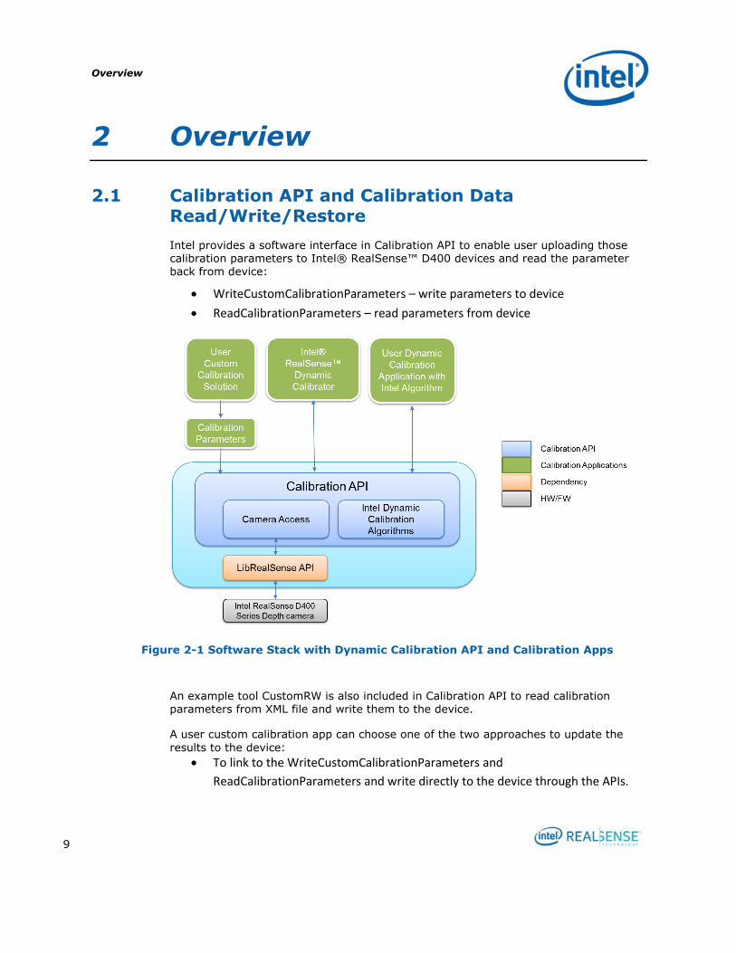
Intel provides a software interface in Calibration API to enable user uploading those calibration parameters to Intel® RealSense™ D400 devices and read the parameter back from device:
WriteCustomCalibrationParameters – write parameters to device
ReadCalibrationParameters – read parameters from device
Figure 2-1 Software Stack with Dynamic Calibration API and Calibration Apps
An example tool CustomRW is also included in Calibration API to read calibration parameters from XML file and write them to the device.
A user custom calibration app can choose one of the two approaches to update the
results to the device:
To link to the WriteCustomCalibrationParameters and
ReadCalibrationParameters and write directly to the device through the APIs.

Overview
10
To write the results into a parameter XML file and then use CustomRW to
read/write the parameters to the device.
In case user needs to restore the calibration data on the device, ResetDeviceCalibration in Calibration API can be called to programmatically restore
the device calibration to gold settings.
ResetDeviceCalibration – restore device calibration to gold settings
The CustomRW example tool also supports restore through command line option.
2.2 Calibration Parameters Calibration parameters includes INTRINSICS and EXTRINSICS. Assume left camera is
the reference camera and is located at world origin. RGB parameters only apply to
modules with RGB, e.g., D415 and D435.
Intrinsic includes
Focal length - specified as [fx; fy] in pixels for left, right, and RGB cameras
Principal point - specified as [px; py] in pixels for left, right, and RGB cameras
Distortion - specified as Brown's distortion model [k1; k2; p1; p2; k3] for left,
right, and RGB cameras
Extrinsic includes
RotationLeftRight - rotation from right camera coordinate system to left camera
coordinate system, specified as a 3x3 rotation matrix
TranslationLeftRight - translation from right camera coordinate system to left
camera coordinate system, specified as a 3x1 vector in millimeters
RotationLeftRGB - rotation from RGB camera coordinate system to left camera
coordinate system, specified as a 3x3 rotation matrix
TranslationLeftRGB - translation from RGB camera coordinate system to left
camera coordinate system, specified as a 3x1 vector in millimeters
The calibration data read/write API allows user to upload both INTRINSICS and
EXTRINSICS. The user custom algorithm is free to optimize all these parameters. The
sample in this document optimizes both intrinsic and extrinsic parameters.
The following table shows how the various calibration tools would impact calibration
parameters for Intel® RealSense™ D400 series depth cameras.
Factory Calibration
OEM Calibration
Technician
Calibration
User Custom Calibration
Dynamic Calibration
Overview
11
Intrinsic x x x x
Extrinsic x x x x x
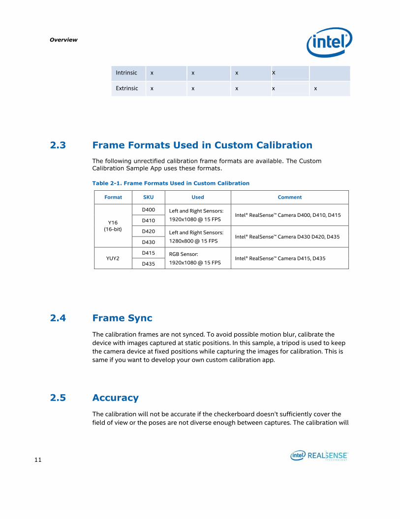
2.3 Frame Formats Used in Custom Calibration
The following unrectified calibration frame formats are available. The Custom
Calibration Sample App uses these formats.
Table 2-1. Frame Formats Used in Custom Calibration
Format SKU Used Comment
Y16 (16-bit)
D400 Left and Right Sensors:
1920x1080 @ 15 FPS Intel® RealSense™ Camera D400, D410, D415
D410
D420 Left and Right Sensors:
1280x800 @ 15 FPS Intel® RealSense™ Camera D430 D420, D435
D430
YUY2 D415 RGB Sensor:
1920x1080 @ 15 FPS Intel® RealSense™ Camera D415, D435
D435
2.4 Frame Sync
The calibration frames are not synced. To avoid possible motion blur, calibrate the
device with images captured at static positions. In this sample, a tripod is used to keep
the camera device at fixed positions while capturing the images for calibration. This is
same if you want to develop your own custom calibration app.
2.5 Accuracy
The calibration will not be accurate if the checkerboard doesn’t sufficiently cover the
field of view or the poses are not diverse enough between captures. The calibration will

Overview
12
also not be accurate if the camera or board is handheld (or not completely still) as there
is no framesync in calibration mode.
Setup
13
3 Setup
This section describes the required hardware and software setup for running the Custom Calibration Sample Application to calibrate a device and developing a Custom Calibration Application.
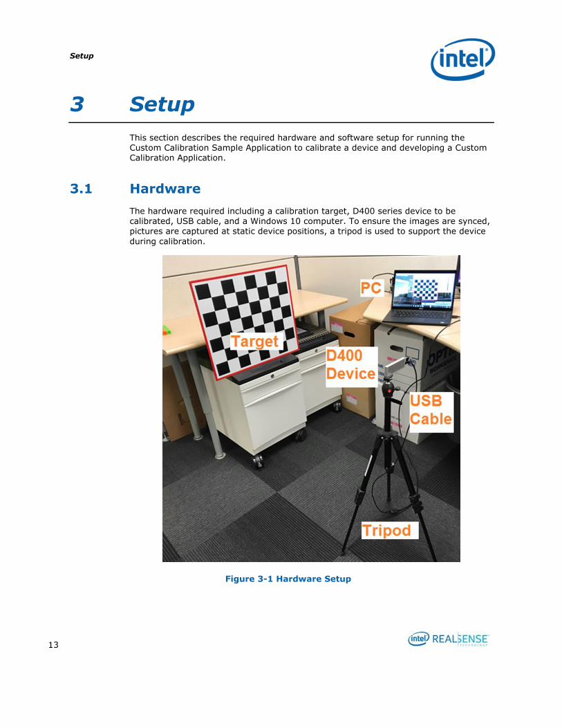
3.1 Hardware
The hardware required including a calibration target, D400 series device to be calibrated, USB cable, and a Windows 10 computer. To ensure the images are synced, pictures are captured at static device positions, a tripod is used to support the device
during calibration.
Figure 3-1 Hardware Setup

Setup
14
3.1.1 Device
Intel® RealSense™ D415 device as shown below is used to show case the custom calibration process. All D400 series devices can use the same process.
Figure 3-2 D415 Device
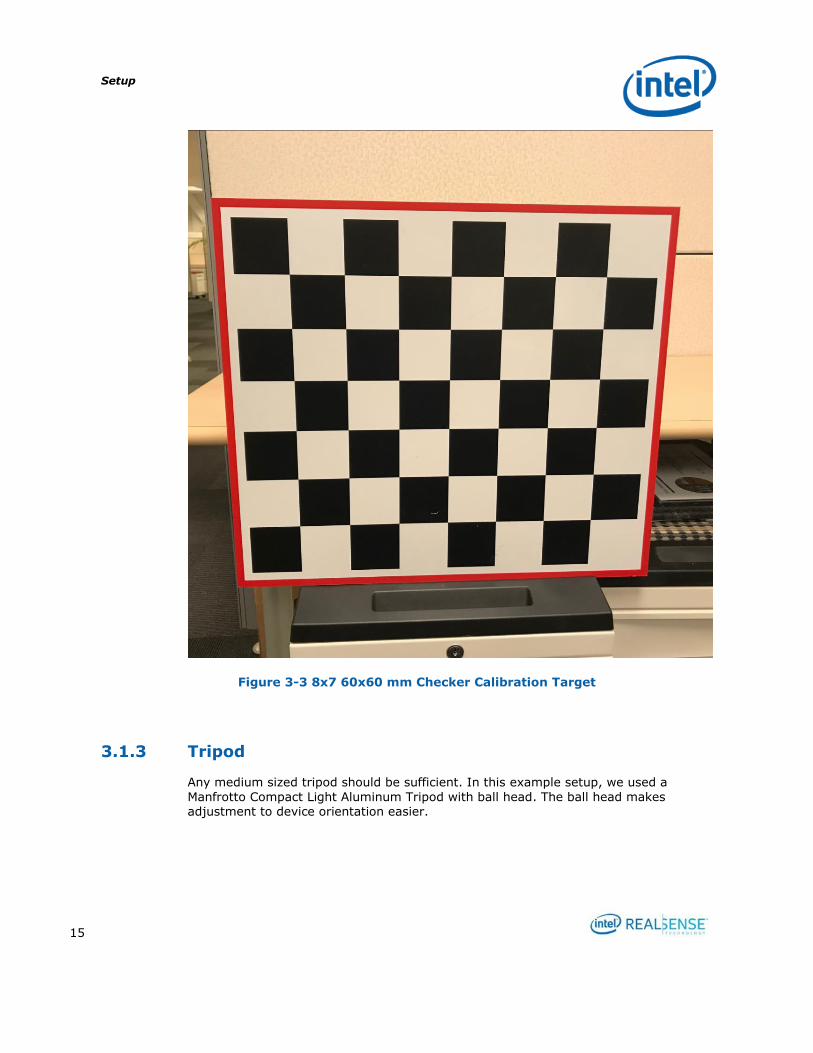
3.1.2 Target
The target used in this custom calibration example is an 8x7 checkerboard with a
60x60mm checker size. The target image pdf 540x480_60mm.pdf is included in the software package described in 3.2.1 Custom Calibration Sample Application. The target pdf is located under the target directory. Users must ensure that when printing the target, the target is not scaled.
A developer may choose to use a different target, but will need to modify the sample application accordingly and recompile.
Setup
15
Figure 3-3 8x7 60x60 mm Checker Calibration Target
3.1.3 Tripod
Any medium sized tripod should be sufficient. In this example setup, we used a
Manfrotto Compact Light Aluminum Tripod with ball head. The ball head makes
adjustment to device orientation easier.

Setup
16
Figure 3-4 Tripod
Setup
17
3.1.4 USB
A long USB type C cable to connect the device to the host computer where the custom calibration sample application will run.
3.1.5 PC
A Windows 10 computer.
3.2 Software
Install the following to the windows computer.
3.2.1 Custom Calibration Sample Application
A CustomCalibrationSample.zip package is provided for the Custom Calibration Sample Application. It includes the binary executable and a calibration target file. The source code is included in Intel® RealSense™ Calibration API package.
Unzip the package:
CustomCalibrationSample |
|---------Bin | |-------- CustomCalibrationSampleApp.exe
| |--------- Target | |-------- 540x480_60mm.pdf | |--------- CustomResult
Bin folder contains the executable. CustomCalibrationSampleApp.exe is the executable for the Custom Calibration Sample Application.
Target contains the target image pdf 540x480_60mm.pdf. User will need to print it
without scaling.
CustomResult contains all device calibration results.

Setup
18
3.2.2 Intel® RealSense™ Calibration Tool and API
The calibration example uses support functions provided by the Intel® RealSense™ Calibration API to store updated calibration parameters into the non-volatile storage on the Intel® RealSense™ D400 series modules. Required functions were first introduced in version 2.5.2.0 of the Dynamic Calibration API, so install the latest
version and ensure that it is version 2.5.2.0 or later. Table 3-1 lists where to download the Intel® RealSense™ Calibration API software and associated documentation.
Table 3-1. Intel® RealSense™ Calibration API Resources
Resource URL
Intel® RealSense™ Depth Module D400 Series Dynamic Calibration Software Download
https://downloadcenter.intel.com/download/27415/?v=t
Intel® RealSense™ Depth Module D400 Series Dynamic Calibration User Guide
https://cdrd.intel.com/v1/dl/getContent/574999.htm
Intel® RealSense™ Depth Module D400 Series Dynamic Calibration Programmer Guide
https://www.intel.com/content/www/us/en/support/articles/000026724.html
Find Calibration Tool and Calibration API installers and follow instruction to install. The latest version 2.5.2.0. After installation, the directory structure should look like below:
CalibrationToolAPI
|
|-------- 2.5.2.0
| |-------- bin
| | |-------- Intel.Realsense.CustomRW.exe
|
| |-------- Include
| |-------- attributions.txt
Setup
19
| |-------- release_notes.txt
| |-------- license.txt
| |-------- gimbal
| |-------- target
| |-------- examples
| | |-------- CustomCalibration
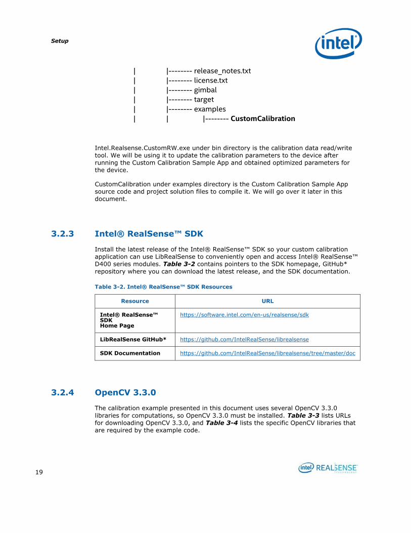
Intel.Realsense.CustomRW.exe under bin directory is the calibration data read/write tool. We will be using it to update the calibration parameters to the device after running the Custom Calibration Sample App and obtained optimized parameters for the device.
CustomCalibration under examples directory is the Custom Calibration Sample App source code and project solution files to compile it. We will go over it later in this document.
3.2.3 Intel® RealSense™ SDK
Install the latest release of the Intel® RealSense™ SDK so your custom calibration application can use LibRealSense to conveniently open and access Intel® RealSense™ D400 series modules. Table 3-2 contains pointers to the SDK homepage, GitHub*
repository where you can download the latest release, and the SDK documentation.
Table 3-2. Intel® RealSense™ SDK Resources
Resource URL
Intel® RealSense™ SDK Home Page
https://software.intel.com/en-us/realsense/sdk
LibRealSense GitHub* https://github.com/IntelRealSense/librealsense
SDK Documentation https://github.com/IntelRealSense/librealsense/tree/master/doc
3.2.4 OpenCV 3.3.0
The calibration example presented in this document uses several OpenCV 3.3.0
libraries for computations, so OpenCV 3.3.0 must be installed. Table 3-3 lists URLs for downloading OpenCV 3.3.0, and Table 3-4 lists the specific OpenCV libraries that are required by the example code.
Setup
20
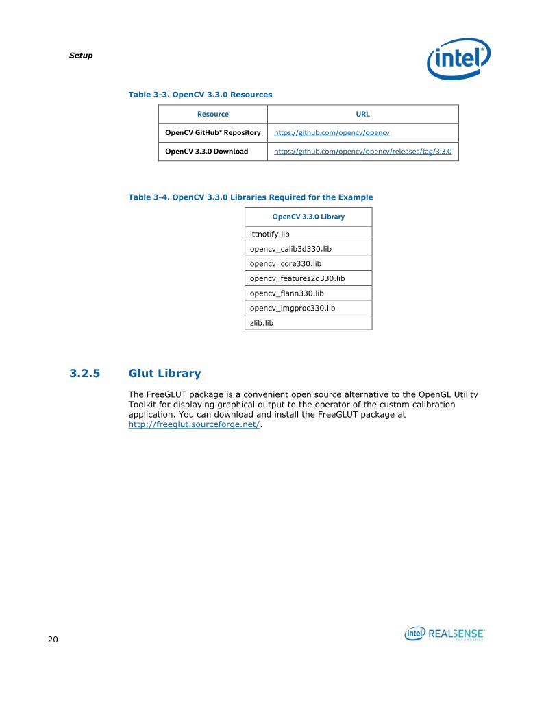
Table 3-3. OpenCV 3.3.0 Resources
Resource URL
OpenCV GitHub* Repository https://github.com/opencv/opencv
OpenCV 3.3.0 Download https://github.com/opencv/opencv/releases/tag/3.3.0
Table 3-4. OpenCV 3.3.0 Libraries Required for the Example
OpenCV 3.3.0 Library
ittnotify.lib
opencv_calib3d330.lib
opencv_core330.lib
opencv_features2d330.lib
opencv_flann330.lib
opencv_imgproc330.lib
zlib.lib
3.2.5 Glut Library
The FreeGLUT package is a convenient open source alternative to the OpenGL Utility
Toolkit for displaying graphical output to the operator of the custom calibration application. You can download and install the FreeGLUT package at http://freeglut.sourceforge.net/.
Calibrating Device with Custom Calibration Sample Application
21
4 Calibrating Device with Custom
Calibration Sample Application
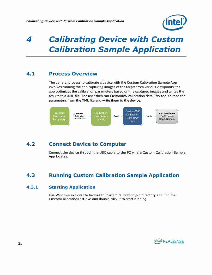
4.1 Process Overview
The general process to calibrate a device with the Custom Calibration Sample App
involves running the app capturing images of the target from various viewpoints, the
app optimizes the calibration parameters based on the captured images and writes the
results to a XML file. The user then run CustomRW calibration data R/W tool to read the
parameters from the XML file and write them to the device.
4.2 Connect Device to Computer
Connect the device through the USC cable to the PC where Custom Calibration Sample
App locates.
4.3 Running Custom Calibration Sample Application
4.3.1 Starting Application
Use Windows explorer to browse to CustomCalibration\bin directory and find the CustomCalibrationTest.exe and double click it to start running.
Calibrating Device with Custom Calibration Sample Application
22
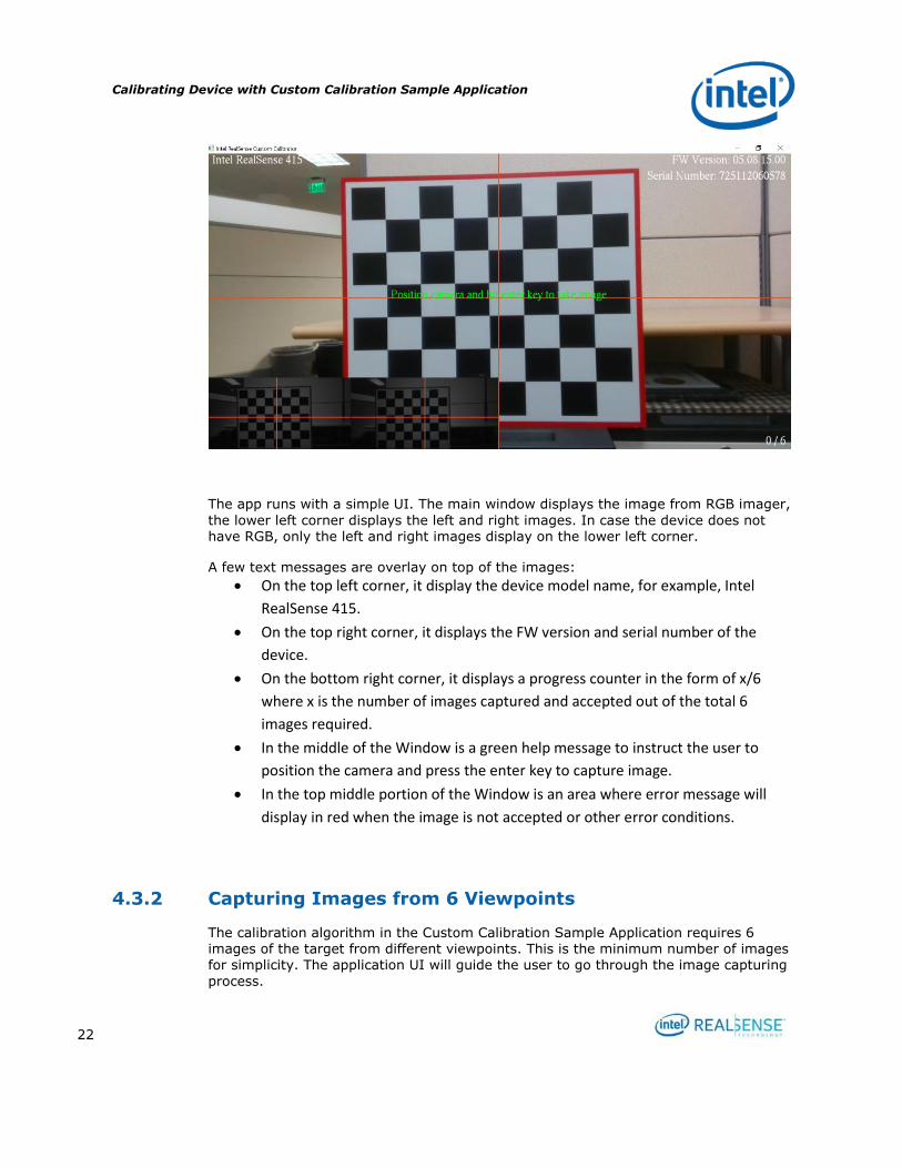
The app runs with a simple UI. The main window displays the image from RGB imager,
the lower left corner displays the left and right images. In case the device does not have RGB, only the left and right images display on the lower left corner.
A few text messages are overlay on top of the images:
On the top left corner, it display the device model name, for example, Intel
RealSense 415.
On the top right corner, it displays the FW version and serial number of the
device.
On the bottom right corner, it displays a progress counter in the form of x/6
where x is the number of images captured and accepted out of the total 6
images required.
In the middle of the Window is a green help message to instruct the user to
position the camera and press the enter key to capture image.
In the top middle portion of the Window is an area where error message will
display in red when the image is not accepted or other error conditions.
4.3.2 Capturing Images from 6 Viewpoints
The calibration algorithm in the Custom Calibration Sample Application requires 6 images of the target from different viewpoints. This is the minimum number of images for simplicity. The application UI will guide the user to go through the image capturing
process.
Calibrating Device with Custom Calibration Sample Application
23
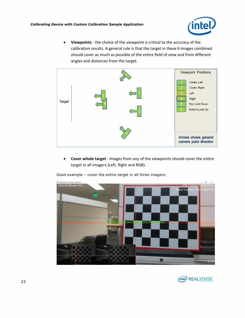
Viewpoints - the choice of the viewpoint is critical to the accuracy of the
calibration results. A general rule is that the target in these 6 images combined
should cover as much as possible of the entire field of view and from different
angles and distances from the target.
Cover whole target - images from any of the viewpoints should cover the entire
target in all imagers (Left, Right and RGB).
Good example – cover the entire target in all three imagers:

Calibrating Device with Custom Calibration Sample Application
24
Bad example - cover only portion of the target in any of the three imagers:
Now, let’s capture the images.
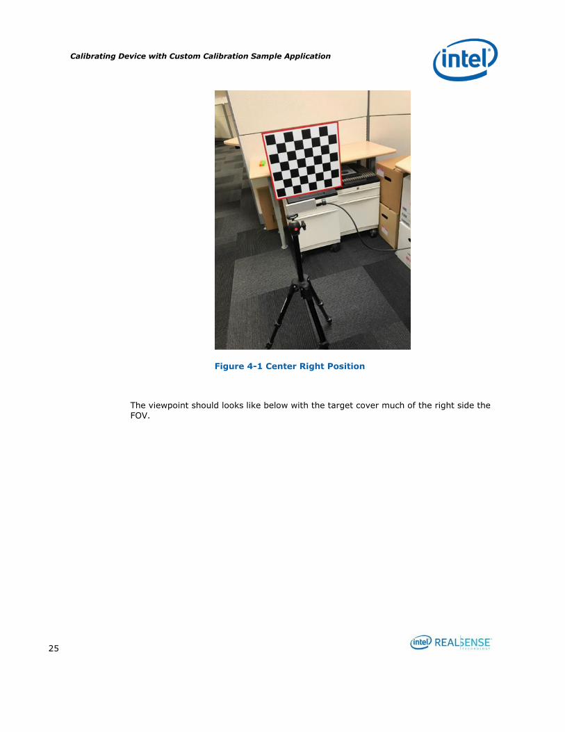
4.3.2.1 Viewpoint #1 – Center Right
Adjust the tripod and position the device on the center right facing directly to the
target.
Calibrating Device with Custom Calibration Sample Application
25
Figure 4-1 Center Right Position
The viewpoint should looks like below with the target cover much of the right side the
FOV.

Calibrating Device with Custom Calibration Sample Application
26
Figure 4-2 Viewpoint #1
Press enter to capture the image. If successful, the frame counter on the lower right corner will increase to 1/6 meaning 1 out of 6 images are captured. If it failed, a red error message will appear and user is directed to retake a viewpoint.
4.3.2.2 Viewpoint #2 - Center Left
Move the device to the center left directly facing the target so the target covers much
of the left portion of the FOV.

Calibrating Device with Custom Calibration Sample Application
27
Figure 4-3 Center Right

Calibrating Device with Custom Calibration Sample Application
28
Figure 4-4 Viewpoint #2
Press enter to capture the image. If successful, the frame counter on the lower right corner will increase to 2/6 meaning 2 out of 6 images are captured. If it failed, a red error message will appear and user is directed to retake a viewpoint.
4.3.2.3 Viewpoint #3 - Left
Move the device to the left of the camera facing the device at an angle. Use the
viewpoint below for reference.

Calibrating Device with Custom Calibration Sample Application
29
Figure 4-5 Left
Figure 4-6 Viewpoint #3

Calibrating Device with Custom Calibration Sample Application
30
Press enter to capture the image. If successful, the frame counter on the lower right
corner will increase to 3/6 meaning 3 out of 6 images are captured. If it failed, a red error message will appear and user is directed to retake a viewpoint.
4.3.2.4 Viewpoint #4 – Right
Move the device to the right facing the target at an angle. Use the viewpoint below for
reference.
Figure 4-7 Right

Calibrating Device with Custom Calibration Sample Application
31
Figure 4-8 Viewpoint #4
Press enter to capture the image. If successful, the frame counter on the lower right corner will increase to 4/6 meaning 4 out of 6 images are captured. If it failed, a red error message will appear and user is directed to retake a viewpoint.
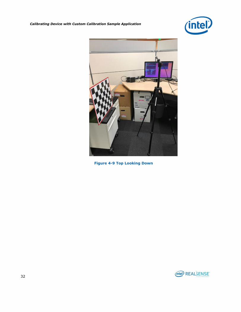
4.3.2.5 Viewpoint #5 – Top Looking Down
Adjust the tripod so the device high enough to look down the target at an angle. Use the viewpoint below for reference.
Calibrating Device with Custom Calibration Sample Application
32
Figure 4-9 Top Looking Down

Calibrating Device with Custom Calibration Sample Application
33
Figure 4-10 Viewpoint #5
Press enter to capture the image. If successful, the frame counter on the lower right corner will increase to 5/6 meaning 5 out of 6 images are captured. If it failed, a red error message will appear and user is directed to retake a viewpoint.
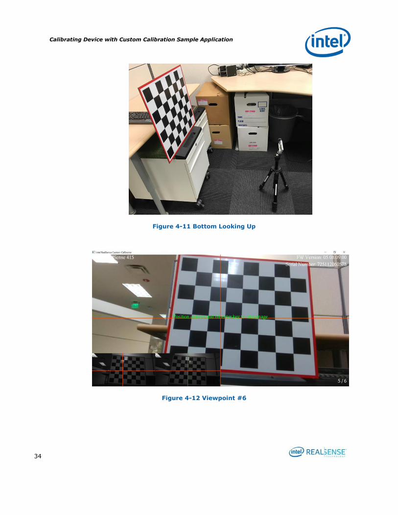
4.3.2.6 Viewpoint #6 – Bottom Looking Up
Folding the tripod so that the device will be in a very low position looking up to the
target. Use the viewpoint below for reference.
Calibrating Device with Custom Calibration Sample Application
34
Figure 4-11 Bottom Looking Up
Figure 4-12 Viewpoint #6
Calibrating Device with Custom Calibration Sample Application
35
Press enter to capture the image. If successful, the frame counter on the lower right
corner will increase to 6/6 meaning 6 out of 6 images are captured. If it failed, a red error message will appear and user is directed to retake a viewpoint.
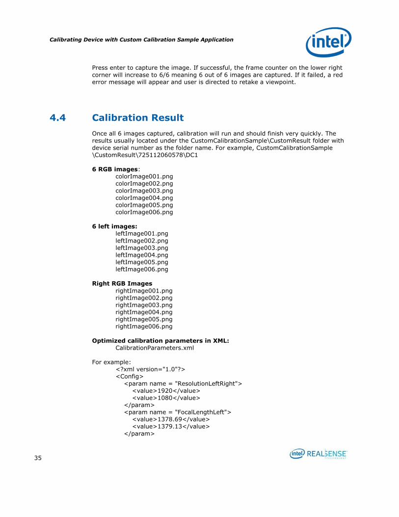
4.4 Calibration Result
Once all 6 images captured, calibration will run and should finish very quickly. The results usually located under the CustomCalibrationSample\CustomResult folder with
device serial number as the folder name. For example, CustomCalibrationSample \CustomResult\725112060578\DC1
6 RGB images: colorImage001.png colorImage002.png colorImage003.png
colorImage004.png colorImage005.png colorImage006.png
6 left images:
leftImage001.png
leftImage002.png leftImage003.png leftImage004.png leftImage005.png leftImage006.png
Right RGB Images
rightImage001.png rightImage002.png rightImage003.png rightImage004.png rightImage005.png rightImage006.png
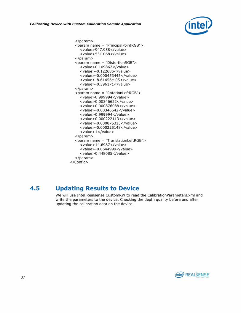
Optimized calibration parameters in XML: CalibrationParameters.xml
For example:
<?xml version="1.0"?> <Config>
<param name = "ResolutionLeftRight"> <value>1920</value>
<value>1080</value> </param> <param name = "FocalLengthLeft"> <value>1378.69</value> <value>1379.13</value>
</param>

Calibrating Device with Custom Calibration Sample Application
36
<param name = "PrincipalPointLeft"> <value>965.562</value> <value>542.603</value> </param> <param name = "DistortionLeft"> <value>0.09689</value>
<value>-0.0235634</value> <value>-5.05513e-05</value> <value>0.000105855</value> <value>-0.640377</value> </param> <param name = "FocalLengthRight"> <value>1389.55</value>
<value>1390.1</value>
</param> <param name = "PrincipalPointRight"> <value>957.402</value> <value>553.108</value> </param>
<param name = "DistortionRight"> <value>0.123289</value> <value>-0.290911</value> <value>0.000149083</value> <value>0.000723527</value> <value>0.0992178</value> </param>
<param name = "RotationLeftRight"> <value>0.999983</value> <value>0.00150008</value> <value>-0.00558928</value>
<value>-0.00150249</value> <value>0.999999</value> <value>-0.000428313</value>
<value>0.00558863</value> <value>0.000436704</value> <value>0.999984</value> </param> <param name = "TranslationLeftRight"> <value>-55.3888</value>
<value>0.0448052</value> <value>1.52189</value> </param> <param name = "HasRGB"> <value>1</value> </param> <param name = "ResolutionRGB">
<value>1920</value> <value>1080</value> </param> <param name = "FocalLengthRGB"> <value>1376.09</value> <value>1376.4</value>
Calibrating Device with Custom Calibration Sample Application
37
</param> <param name = "PrincipalPointRGB"> <value>947.958</value> <value>531.068</value> </param> <param name = "DistortionRGB">
<value>0.109862</value> <value>-0.122685</value> <value>-0.000453445</value> <value>-8.61456e-05</value> <value>-0.396171</value> </param> <param name = "RotationLeftRGB">
<value>0.999994</value>
<value>0.00346622</value> <value>0.000876088</value> <value>-0.00346642</value> <value>0.999994</value> <value>0.000222113</value>
<value>-0.000875313</value> <value>-0.000225148</value> <value>1</value> </param> <param name = "TranslationLeftRGB"> <value>14.6987</value> <value>-0.0644999</value>
<value>0.448085</value> </param> </Config>
4.5 Updating Results to Device We will use Intel.Realsense.CustomRW to read the CalibrationParameters.xml and write the parameters to the device. Checking the depth quality before and after updating the calibration data on the device.
Calibrating Device with Custom Calibration Sample Application
38
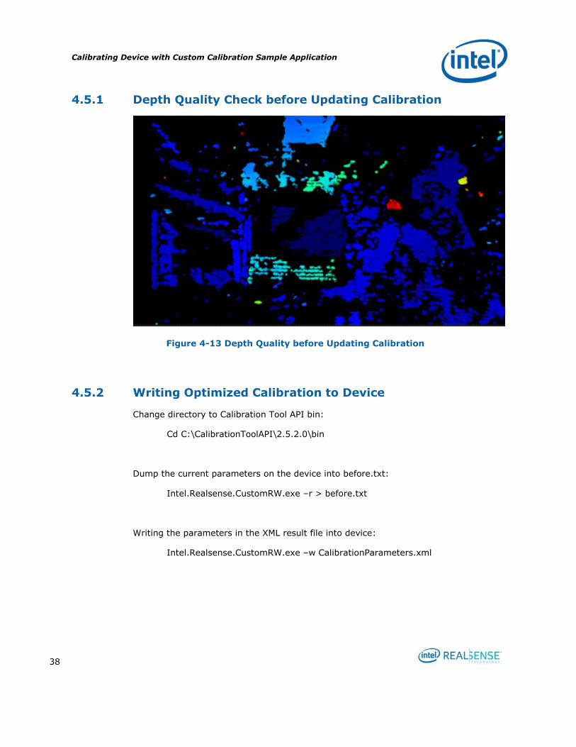
4.5.1 Depth Quality Check before Updating Calibration
Figure 4-13 Depth Quality before Updating Calibration
4.5.2 Writing Optimized Calibration to Device
Change directory to Calibration Tool API bin:
Cd C:\CalibrationToolAPI\2.5.2.0\bin
Dump the current parameters on the device into before.txt:
Intel.Realsense.CustomRW.exe –r > before.txt
Writing the parameters in the XML result file into device:
Intel.Realsense.CustomRW.exe –w CalibrationParameters.xml
Calibrating Device with Custom Calibration Sample Application
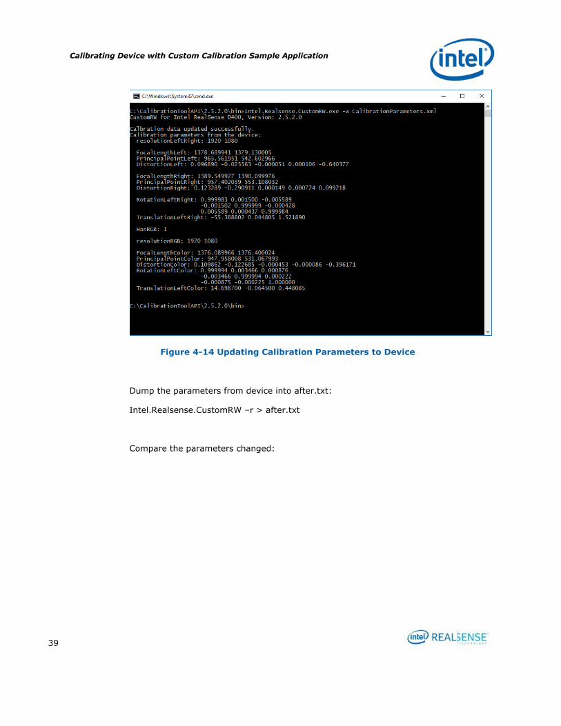
39
Figure 4-14 Updating Calibration Parameters to Device
Dump the parameters from device into after.txt:
Intel.Realsense.CustomRW –r > after.txt
Compare the parameters changed:
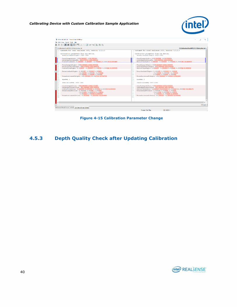
Calibrating Device with Custom Calibration Sample Application
40
Figure 4-15 Calibration Parameter Change
4.5.3 Depth Quality Check after Updating Calibration
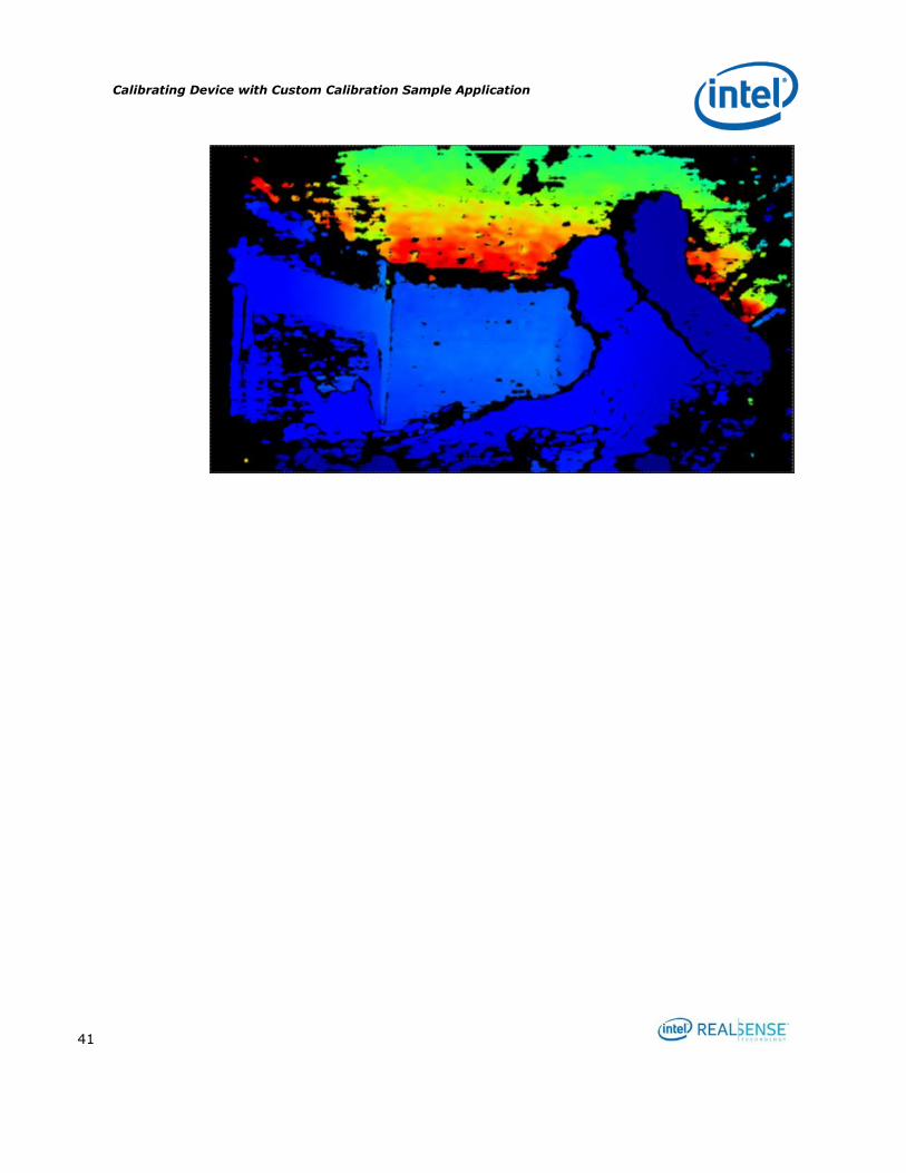
Calibrating Device with Custom Calibration Sample Application
41
Developing Custom Calibration Application
42
5 Developing Custom Calibration
Application
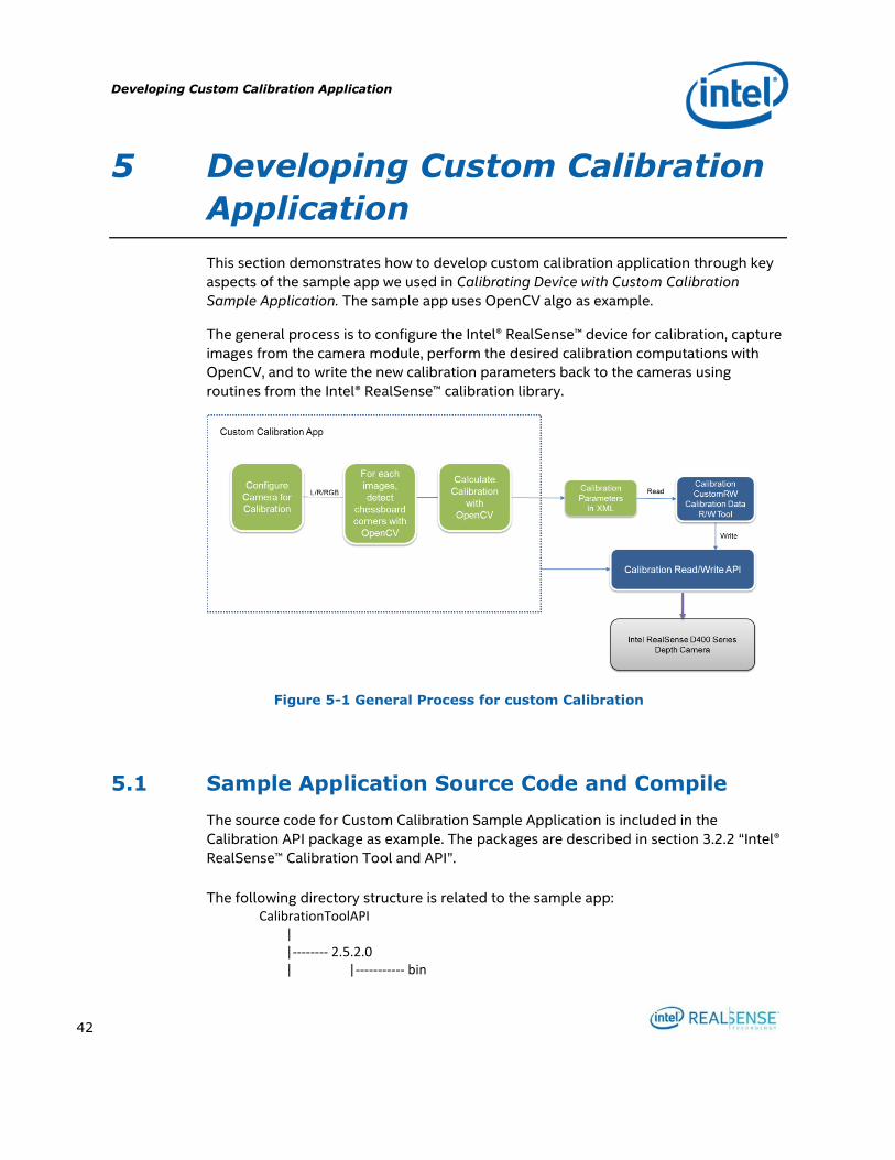
This section demonstrates how to develop custom calibration application through key
aspects of the sample app we used in Calibrating Device with Custom Calibration
Sample Application. The sample app uses OpenCV algo as example.
The general process is to configure the Intel® RealSense™ device for calibration, capture
images from the camera module, perform the desired calibration computations with
OpenCV, and to write the new calibration parameters back to the cameras using
routines from the Intel® RealSense™ calibration library.
Figure 5-1 General Process for custom Calibration
5.1 Sample Application Source Code and Compile
The source code for Custom Calibration Sample Application is included in the
Calibration API package as example. The packages are described in section 3.2.2 “Intel®
RealSense™ Calibration Tool and API”.
The following directory structure is related to the sample app:
CalibrationToolAPI | |-------- 2.5.2.0 | |----------- bin
Developing Custom Calibration Application
43
| | |------- DSDynamicCalibrationAPI.dll | | |------- freeglut.dll | | |------- realsense2.dll | | | |-------- Include | | |------- DSDynamicCalibration.h | | |------- DSOSUtils.h | | |------- DSShared.h | | | |------------- lib | | |------- DSDynamicCalibrationAPI.lib | | | |-------- librealsense | | |------- include | | |------- lib | | | |-------- examples | | |------- CustomCalibration | | | |-------- CalibrationManager.cpp | | | |-------- CalibrationManager.h | | | |-------- CustomCalibration.cpp | | | |-------- CustomCalibration.h | | | |-------- CustomCalibrationWrapper.cpp | | | |-------- CustomCalibrationWrapper.h | | | |-------- Rs400Dev.cpp | | | |-------- Rs400Dev.h | | | |-------- FileOp.h | | | |-------- Main.cpp | | | |-------- CustomCalibrationTest.vcxproj | | | |-------- CustomCalibrationTest.sln
| | | | |------- Common | | | |-------- CalibParamXmlWrite.h | | | | |------- ThirdParty | | | |-------- glut
The sample app depends on a few third party libraries, including GLUT, LibRealSense, and OpenCV 3.3. GLUT is included under examples\ThirdParty\glut. LibRealSense is included under librealsense.
bin contains the runtime libraries for Calibration API, GLUT, and LibRealSense.
Include contains header files for Calibration API.
lib contains Calibration API library.
librealsense contains the header files and libraries for LibRealSense
Developing Custom Calibration Application
44
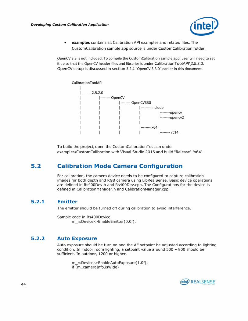
examples contains all Calibration API examples and related files. The
CustomCalibration sample app source is under CustomCalibration folder.
OpenCV 3.3 is not included. To compile the CustomCalibration sample app, user will need to set
it up so that the OpenCV header files and libraries is under CalibrationToolAPI\2.5.2.0.
OpenCV setup is discussed in section 3.2.4 “OpenCV 3.3.0” earlier in this document.
CalibrationToolAPI | |-------- 2.5.2.0 | |-------- OpenCV | | |-------- OpenCV330 | | | |-------- include | | | | |--------opencv | | | | |--------opencv2 | | | | | | | |-------- x64 | | | | |-------- vc14
To build the project, open the CustomCalibrationTest.sln under
examples\CustomCalibration with Visual Studio 2015 and build “Release” “x64”.
5.2 Calibration Mode Camera Configuration
For calibration, the camera device needs to be configured to capture calibration
images for both depth and RGB camera using LibRealSense. Basic device operations are defined in Rs400Dev.h and Rs400Dev.cpp. The Configurations for the device is defined in CalibrationManager.h and CalibrationManager.cpp.
5.2.1 Emitter
The emitter should be turned off during calibration to avoid interference. Sample code in Rs400Device: m_rsDevice->EnableEmitter(0.0f);
5.2.2 Auto Exposure
Auto exposure should be turn on and the AE setpoint be adjusted according to lighting condition. In indoor room lighting, a setpoint value around 500 – 800 should be sufficient. In outdoor, 1200 or higher. m_rsDevice->EnableAutoExposure(1.0f); if (m_cameraInfo.isWide)
Developing Custom Calibration Application
45
m_rsDevice->SetAeControl(800); else m_rsDevice->SetAeControl(500);
5.2.3 Streaming Resolution and Format
Calibration frame resolutions and formats are described in Table 2-1 Frame Formats Used in Custom Calibration, for example, in this sample, or D415 device, the
resolution is 1920x1080 with frame rate of 15 fps. The L/R format is Y16 and the RGB format is YUY2. m_rsDevice->SetMediaMode(m_width, m_height, m_fps, m_rgbWidth, m_rgbHeight, m_cameraInfo.isRGB);
m_rsDevice->StartCapture([&](const void *leftImage, const void *rightImage,
const void *colorImage, const uint64_t timeStamp)
5.2.4 Image Captures
The sample app captures 6 images. More images from different positions may improve accurate. The number of images is defined in CalibrationManager.h:
const int NUM_SHOTS = 6;
5.2.5 Demosaic Left/Right Images for ASR / PSR SKUs
For ASR/PSR SKUs, left and right images need to be demosaiced.
5.3 Detecting the Chessboard in an Image with OpenCV
For each of the captured images, find the chessboard corners with OpenCV findChessboardCorners.
#include <opencv2/opencv.hpp> #include <opencv2/core/core.hpp> #include <opencv2/calib3d.hpp> #include <vector> using namespace std; using namespace cv; bool DetectChessboard(const Mat& image, const Size& chessboardSize, vector<Point2f>& corners)
Developing Custom Calibration Application
46
{ // Find chessboard corners if (!findChessboardCorners(image, chessboardSize, corners, CALIB_CB_ADAPTIVE_THRESH | CALIB_CB_NORMALIZE_IMAGE | CALIB_CB_FILTER_QUADS)) return false; // Refine them cornerSubPix(image, corners, Size(11, 11), Size(-1, -1), TermCriteria(CV_TERMCRIT_EPS | CV_TERMCRIT_ITER, 30, 0.1)); return true; }
5.4 Calculating Depth Camera Calibration with OpenCV
#include <opencv2/opencv.hpp> #include <opencv2/core/core.hpp> #include <opencv2/calib3d.hpp> #include <vector> using namespace std; using namespace cv; static void CreateCorners3D(const Size& chessboardSize, float checkerSize, size_t numImages, vector<vector<Point3f> >& corners3D) { corners3D.resize(numImages); corners3D[0].resize(chessboardSize.width * chessboardSize.height); for (int i = 0; i < chessboardSize.height; i++) for (int j = 0; j < chessboardSize.width; j++) corners3D[0][i * chessboardSize.width + j] = Point3f(j * checkerSize, i * checkerSize, 0.0f); for (size_t i = 1; i < numImages; i++) corners3D[i] = corners3D[0]; } double CalibrateDepthCamera(const vector<vector<Point2f> >& cornersLeft, const vector<vector<Point2f> >& cornersRight, const Size& chessboardSize, float checkerSize, const Size& imageSizeLR, Mat& Kl, Mat& Dl, Mat& Kr, Mat& Dr, Mat& Rlr, Mat& Tlr) { CV_Assert(cornersLeft.size() != 0 && cornersLeft.size() == cornersRight.size()); CV_Assert(checkerSize > 0.0f); // Create 3D prototype of the corners vector<vector<Point3f> > corners3D; CreateCorners3D(chessboardSize, checkerSize, cornersLeft.size(), corners3D); // Calibrate each camera individualy calibrateCamera(corners3D, cornersLeft, imageSizeLR, Kl, Dl, noArray(), noArray(), CV_CALIB_FIX_ASPECT_RATIO, TermCriteria(TermCriteria::COUNT + TermCriteria::EPS, 60, DBL_EPSILON)); calibrateCamera(corners3D, cornersRight, imageSizeLR, Kr, Dr, noArray(), noArray(), CV_CALIB_FIX_ASPECT_RATIO, TermCriteria(TermCriteria::COUNT + TermCriteria::EPS, 60, DBL_EPSILON));

Developing Custom Calibration Application
47
// Calibrate the extrinsics between them return stereoCalibrate(corners3D, cornersLeft, cornersRight, Kl, Dl, Kr, Dr, Size(-1, -1), Rlr, Tlr, noArray(), noArray(), CV_CALIB_FIX_INTRINSIC | CV_CALIB_USE_INTRINSIC_GUESS, TermCriteria(TermCriteria::COUNT + TermCriteria::EPS, 300, DBL_EPSILON)); }
5.5 Calculating RGB Camera Calibration with OpenCV
Note: Assumes good depth camera calibration
double CalibrateRGBCamera(const vector<vector<Point2f> >& cornersLeft, const vector<vector<Point2f> >& cornersRGB, const Size& chessboardSize, float checkerSize, const Size& imageSizeRGB, const Mat& Kl, const Mat& Dl, Mat& Kc, Mat& Dc, Mat& Rlc, Mat& Tlc) { CV_Assert(cornersLeft.size() != 0 && cornersLeft.size() == cornersRGB.size()); CV_Assert(checkerSize > 0.0f); // Create 3D prototype of the corners vector<vector<Point3f> > corners3D; CreateCorners3D(chessboardSize, checkerSize, cornersLeft.size(), corners3D); // Calibrate RGB camera calibrateCamera(corners3D, cornersRGB, imageSizeRGB, Kc, Dc, noArray(), noArray(), CV_CALIB_FIX_ASPECT_RATIO, TermCriteria(TermCriteria::COUNT + TermCriteria::EPS, 60, DBL_EPSILON)); // Calibrate the extrinsics between them return stereoCalibrate(corners3D, cornersLeft, cornersRGB, Kl, Dl, Kc, Dc, Size(-1, -1), Rlc, Tlc, noArray(), noArray(), CV_CALIB_FIX_INTRINSIC | CV_CALIB_USE_INTRINSIC_GUESS, TermCriteria(TermCriteria::COUNT + TermCriteria::EPS, 300, DBL_EPSILON)); }
5.6 Calculating RGB Camera Calibration Extrinsics with OpenCV
Note: Assumes good depth camera calibration and intrinsics for the RGB camera.
The CustomCalibration.h header file in the sample code contained the following
unimplemented prototype:
double RecalibrateRGBCamera(const std::vector<std::vector<cv::Point2f> >& cornersLeft, const std::vector<std::vector<cv::Point2f> >& cornersRGB, const cv::Size& chessboardSize, float checkerSize, const cv::Mat& Kl, const cv::Mat& Dl, const cv::Mat& Kc, const cv::Mat& Dc, cv::Mat& Rlc, cv::Mat& Tlc);
Developing Custom Calibration Application
48
5.7 Writing Calibration Parameters A user custom calibration app can choose one of the two approaches to update the
results to the device:
To link to the WriteCustomCalibrationParameters and
ReadCalibrationParameters and write directly to the device through the APIs.
To write the results into a parameter XML file and then use CustomRW to
read/write the parameters to the device.
Custom Calibration Sample Application write the results into a parameter XML file and
use CustomRW to update the calibration parameters to the device.

Developing Custom Calibration Application
49


![Rainfall Recharge Distribution Figure 4 · F:\Jobs\689\D\Report\Figures\modelling figures\[calibration hydrographs.xls]FigA Calibration Hydrographs Figure 4.7 SRC1 165 166 167 168](https://img.dokumen.tips/doc/110x75/5f638629c44902391a394672/rainfall-recharge-distribution-figure-4-fjobs689dreportfiguresmodelling-figurescalibration.jpg)