Embed Size (px)
Citation preview
ORIGINAL ARTICLE
Integrity monitoring algorithms for airport surface movement
Wolfgang Schuster • Jie Bai • Shaojun Feng •
Washington Ochieng
Received: 30 September 2010 / Accepted: 18 January 2011 / Published online: 8 February 2011
� Springer-Verlag 2011
Abstract Navigation algorithms are proposed for carrier
phase ambiguity integrity monitoring to support aircraft
surface movement. The enhanced integrity monitoring
algorithm addresses the very stringent integrity require-
ments for surface movement by the use of multiple test
statistics and a group separation concept for single and
multiple failure detection and exclusion. The algorithms
are subject to a detailed performance characterization for
precision approaches and airport surface movement, using
simulations as well as static and dynamic field trials, taking
into account operational specificities, such as multipath and
potential decorrelations between the reference station and
aircraft due to ionospheric anomalies. Results show that the
proposed algorithms have the potential to satisfy airport
surface movement requirements if the ionospheric anom-
alies are monitored using a special ground-based network.
Keywords Integrity � Ambiguity resolution � Airport
surface movement � RTK � E-GBAS � E-CRAIM
Introduction
Studies have shown that airport surface movement (ASM)
is one of the bottlenecks within the chain of aircraft gate-
to-gate operations and is thus critical to the optimization of
operational capacity. Currently, surface movement radar is
the basic means for surface surveillance. However, the
aircraft position provided by radar is approximate and
therefore has a limited role in facilitating an increase in
capacity both under nominal and poor visibility conditions.
Therefore, to increase situational awareness and mitigate
potential runway incursions, future Advanced Surface
Movement Guidance and Control Systems (A-SMGCS)
must have access to a system capable of providing the
position, velocity and time (PVT) of aircraft and other
vehicles with very high accuracy, integrity, continuity, and
availability.
The current focus in the USA is on the development of a
CAT III Ground-Based Augmentation System (GBAS)
architecture using code-based single-frequency Global
Positioning System (GPS) observables (Boeing 2005).
However, the proposed architecture is not expected to meet
the significantly more stringent taxiing accuracy (0.5 m,
95%) and alert limit (1.4 m) requirements proposed in
Schuster and Ochieng (2011a). A subsequent investigation
into the performance of GNSS determined that code-based
solutions, whether stand-alone or using GBAS, are not able
to provide the required sub-meter accuracy with the level
of integrity required for surface movement (Schuster et al.
2009). Therefore, surface movement operations require the
use of carrier phase measurements in Real Time Kinematic
(RTK) mode with ambiguities resolved on-the-fly (OTF).
From the perspectives of optimization of navigation
infrastructure and cost effectiveness, it is sensible to
include the carrier phase-based ASM navigation function-
ality in the GBAS architecture for CAT III.
We develop a carrier phase-based High-Performance
Navigation (HP-NAV) algorithm, with a focus on reliable
and robust integrity monitoring, to achieve the required
navigation system performance for ASM. The core of the
algorithm is an Extended Carrier phase Receiver Autono-
mous Integrity Monitoring (E-CRAIM) module. It includes
a Minimum Constellation Method (MCM) to speed up the
initial ambiguity fix, an enhanced ambiguity validation
module and a re-search procedure in the case where the
W. Schuster (&) � J. Bai � S. Feng � W. Ochieng
Imperial College, London, UK
e-mail: [email protected]
123
GPS Solut (2012) 16:65–75
DOI 10.1007/s10291-011-0209-9

ambiguity was not fixed on the first iteration. These are
described in the following sections. The paper concludes
with a characterization of the performance of the HP-NAV
algorithm with simulated and real-flight data.
Extended carrier phase integrity monitoring concept
Figure 1 presents the basic structure of the HP-NAV
user-level algorithm for surface movement (Bai et al.
2008). It comprises of a number of functional modules:
data input and output for single- or multiple-GNSS
and Extended Ground-Based Augmentation Systems
(E-GBAS) (Schuster and Ochieng 2011b), data prepro-
cessing, positioning and navigation, and integrity moni-
toring. The data preprocessing module employs a number
of models for the mitigation of the effects of the iono-
sphere, troposphere, multipath, and cycle slips. The
outputs from this module are the carrier phase smoothed
pseudorange and carrier phase observables. The posi-
tioning solutions can be computed by the use of either
least squares estimation or extended Kalman filtering
(EKF). The focus of this research, integrity monitoring,
is based on an Extended Carrier phase Receiver Auton-
omous Integrity Monitoring (E-CRAIM) scheme that
includes monitoring in the ambiguity (i.e., ambiguity
validation) and positioning domains. E-CRAIM is a
derivative of conventional C-RAIM (Ochieng et al. 2007;
Schuster et al. 2007; Feng et al. 2008), with the fol-
lowing additional features.
• Advanced ambiguity resolution with re-search and re-
validation in case of initial failure.
• Failure detection with fixed ambiguity.
• Protection level (PL) estimations based on either
external or onboard observable error estimation.
Each of the above features is addressed in turn below.
Ambiguity resolution and validation
Past studies have shown that the LAMBDA method
(Teunissen 1995), a combination of least squares and
efficient ambiguity search, has the highest possible suc-
cess rate of all integer ambiguity estimators (Teunissen
1999). However, LAMBDA is not designed to mitigate
measurement errors. On the other hand, the MCAR is
able to mitigate measurement errors using multiple-fre-
quency observables. However, its main weaknesses are
amplified noise and multipath. These limitations are
addressed here by exploiting an ambiguity resolution
scheme (Fig. 2) that combines these two methods. Note
that only the dual-frequency scenario is shown in Fig. 2
for ease of comprehension. The triple frequency process
follows the same procedure with an additional extra-
widelane step.Fig. 1 High-level flowchart of HP-NAV software
Fig. 2 Ambiguity search
procedure—high-level overview
66 GPS Solut (2012) 16:65–75
123

The ambiguity search procedure consists of the follow-
ing steps:
• Double-differenced L1 smoothed code phase data are
used to estimate the receiver position. Due to the
relatively short baselines, as would be expected within
an airport environment, the expectation is that the
initial smoothed code-based estimation should deliver
decimeter-level accuracy and thereby facilitate the
direct resolution of the L1 carrier phase ambiguity.
• A LAMBDA search is executed as a first attempt to
resolve the L1 integer ambiguities.
• The ambiguity results from LAMBDA are sent to the
validation module.
• If the L1 ambiguities pass the validation test, they are used
to compute the antenna position; otherwise the process is
repeated with double-differenced widelane data.
The process for double-differenced widelane involves
the use of smoothed code to estimate the float widelane
ambiguities. Given the relatively long wavelength, the float
ambiguities and the corresponding variances and covari-
ances are typically well estimated. As in the case of L1,
float widelane ambiguities are sent to the LAMBDA search
module followed by the validation process. If the widelane
ambiguities pass the validation test, they are used subse-
quently to estimate the L1 ambiguities with the more
accurate range estimation. The L1 ambiguity estimation
and validation processes are then repeated until the L1
ambiguities pass the validation test, yielding the final PVT
solution. If the widelane ambiguities do not pass the vali-
dation test and a third frequency signal is available, the
extra-widelane observables are used to repeat the ambi-
guity search procedure until the L1 ambiguities are fixed. If
the L1 ambiguities cannot be resolved, the PVT solution is
based on float ambiguities.
The scheme described above is designed to start with the
direct resolution of the L1 carrier phase ambiguities and only
uses widelane and ultimately extra-widelane observables if
the preceding step fails. This order is inverted compared to
the original MCAR method to reduce computation time for
real-time applications. It is justifiable on the basis that the
short baselines, aided by a ground monitoring network for
ionospheric anomalies (Schuster and Ochieng 2011b),
should result in a relatively high proportion of successful
resolution of L1 ambiguities, without the need to use the
widelane or extra-widelane observables. This ground mon-
itoring network consists essentially of a few range and
position-domain monitors placed strategically on the airport
surface, augmenting the core GBAS architecture foreseen
for CAT III precision landings.
Enhanced ambiguity validation
The uncertainty of parameter estimators implies that an
integer fixed solution is not always correct. Therefore, a
procedure is executed to validate the integer ambiguity
solution and is tightly linked to the ambiguity search
method. The typical search procedure for single-frequency
measurements comprises the following steps.
• Estimation of the float ambiguities using both carrier
and code phase observables.
• Search for integer ambiguities.
• Estimation of the least squares solution using carrier
phase and fixed integer ambiguities.
The most common ambiguity validation methods are
empirical, such as the F-Test in the measurement domain.
However, the F-Test requires fine-tuning for each specific
operational environment. Therefore, for widely varying
environmental conditions, as encountered when taxiing
from the runway with open space to the ramp with build-
ings nearby, the use of these validation methods with
empirical thresholds on their own are expected to have low
success rates (Bai 2008). A different type of validation
method is the integer aperture (IA) (Verhagen and Teun-
issen 2006). It is based on the concept of pull-in region,
shown as black hexagons in Fig. 3. Provided the float
ambiguity distribution, shown in gray, is centered on one of
the acceptance regions of the ratio test, shown in red, the
corresponding fixed solution is accepted.
The left panel shows the unbiased case. The two panels
on the right show the effect of a bias in the observations. It
is clear that if the bias is sufficiently large, there is a high
probability of accepting the wrong ambiguity solution.
Fig. 3 Concept of pull-in
region in IA method
GPS Solut (2012) 16:65–75 67
123
Therefore, it is essential to use a reliable bias detector with
this method.
Building on the strengths of the ambiguity validation
methods above, an enhanced ambiguity validation scheme
is developed below. It focuses on building the appropriate
test statistics under the null hypothesis and alternative
hypothesis as well as the appropriate thresholds. While
there is no standard criterion for choosing test statistics, the
emphasis is placed on the following criteria:
• the decision logic is based on raw observable data as
much as possible;
• minimization of assumptions and approximations;
• the decision logic can be applied to both code and
carrier phase observables as well as combinations
thereof.
Based on the above considerations, the F-test is suitable
for L1 ambiguity validation, referred to in the rest of the
paper as the ‘‘L1-test’’. The test statistic is given by:
T ¼ r2
r2y
ð1Þ
where
r2 ¼rT G�1
y r
mð2Þ
and m is the number of degrees of freedom; G the cofactor
matrix of the variance–covariance matrix of the
observables y and r is the vector of residuals.
Ambiguities are accepted when:
r2
r2y
\FFAðm:1Þ
where FFA is the value of the central F-distribution for the
required probability of false alert (FA).
Since in the presence of E-GBAS, it is highly unlikely
that a bias of more than half a wavelength is present in the
extra-widelane/widelane ambiguity estimation; the IA
method is chosen for this test. Note, however, that for
optimal performance, it is advisable to use the IA test
alongside the F-test to guarantee a very high level of
protection against any residual bias.
If L1 ambiguities cannot be resolved at the first iteration,
extra-widelane and widelane solutions progressively pro-
vide improved range estimations to enable the L1 ambi-
guities to be resolved. In case the extra-widelane or
widelane ambiguities cannot pass the IA test, a large error is
likely to exist in the observables or in the estimated range.
In this case, the ranges are re-estimated using a different
satellite configuration. If extra-widelane and widelane
ambiguities are resolved, the MCAR procedure continues
with the L1 ambiguity validation, which determines whe-
ther re-search and re-validation procedures are required.
The L1-test effectively makes the final decision as to
whether the carrier phase-based positioning algorithm
provides the correct integer ambiguity values. The method
to generate the test statistics for the L1-test and to deter-
mine the threshold is described in more detail in Sect.
‘‘Ambiguity re-search and re-validation.’’ While past
algorithms typically use the float solution if the L1-test fails
as a result of incorrect integer ambiguity resolution, this
paper proposes a re-search and re-validation procedure to
maximize algorithm performance and system availability.
Ambiguity re-search and re-validation
Sub-meter level accuracy, of the same order of magnitude
as the wavelength of the widelane observables (*86 cm),
should be achievable with double-differenced carrier phase
smoothed code phase observables. For most cases, the
correct widelane ambiguity will therefore be in the range
between N-1 and N?1, where N is the estimated integer
ambiguity based on the float ambiguity. In order to maxi-
mize availability, a search of all float ambiguities within
this region is carried out until the L1-test is passed. The
search begins with the float ambiguity nearest to the edge
of the pull-in region and takes 3n-1 steps for the full tree
(FT), where n is the number of ambiguities. The search
procedure is terminated as soon as the L1-test is passed.
The main drawback of this method is the significant
computational burden. This makes it impractical, espe-
cially for multiple constellation satellite configurations.
Moreover, this method neglects the fact that the probability
of the correct ambiguity being located at lower values of
the initial integer estimation is different to that of the
correct ambiguity being located at higher values. For
example, consider the hypothetical case where the float
estimation is 4.56 and the initial integer estimation is 5. If 5
is not correct, 6 would have a lower probability to be
correct than 4. Therefore, it would not be efficient to test 6
immediately after testing 5.
In order to significantly reduce the computation time, an
improved search scheme is proposed to determine the most
likely direction in the above method, thereby optimizing
the search. A change in the widelane ambiguity by one unit
causes a significantly larger change in the L1 ambiguity,
which is easily detected by comparing the sum-square-
error (SSE) results from the C-RAIM algorithm. If the SSE
value is above a given threshold, all branches from that
knot are ignored in the search. The barrier threshold can be
determined empirically, for example, based on the failure
detection threshold in C-RAIM.
An alternative method, used here, is the Index-Moni-
tored Bootstrap (IMB) re-search and re-validation proce-
dure, presented in Teunissen (2001). Assuming that the
code-based position error is less than the wavelength of
68 GPS Solut (2012) 16:65–75
123
widelane, or extra-widelane, i.e., as would be typical for
the short baselines for GBAS-based systems, the correct
ambiguity values are expected to be one of the two integers
closest to the float value. In other words, the correct
ambiguity solution is likely to be a combination of the best
and second best integer estimations of the elements in the
ambiguity set. The order of switching between the various
ambiguities is based on the following rules:
• Minimize the number of elements that are changed.
• Apply changes to the ambiguity values according to
their distance to the edge of the pull-in region, starting
with the ambiguity values closest to the edge.
This is equivalent to a combination traversal problem
and takes a total of 2n-1 steps to search the entire candi-
date set. This method is significantly faster and more
efficient than FT. However, irrespective of the method
used, the re-search and re-validation scheme still requires
significant computational resources that could hamper its
use in real time. Therefore, for time critical applications,
for example, with short time-to-alerts such as for surface
movement, it is important to minimize the time to ambi-
guity resolution. This is accomplished by using the MCM
below in combination with the IMB.
Minimum constellation method
It is well known that the noise in the double-differenced
residuals increases with decreasing satellite elevation, and
that this makes integer ambiguity resolution at lower ele-
vation difficult. Furthermore, it is the tradition to use the
largest possible number of satellites in the computation of
the position of the user. However, and particularly in the
case of multiple constellations, the question of an optimal
configuration for the best position solution is still to be
agreed. The approach taken here consists of two steps:
• Resolve the ambiguities for a reduced set of satellites,
excluding those at low elevations.
• Use the resolved ambiguities in the first step to aid the
resolution of the remaining satellites and use all the
satellites to exploit the better geometry and measure-
ment redundancy for position estimation.
The procedure above significantly increases the speed
and reliability of ambiguity resolution. In order to ensure a
minimum consistency check capability, at least 5 satellites
are required for the minimum constellation. Therefore, for
nominal scenarios, the satellites with the five highest ele-
vations are used for the minimum constellation calculation.
In the case of a combined GPS-Galileo system, for exam-
ple, there may be up to 20 satellites in view and the
geometry of the five highest satellites may be weak. In this
case, the five satellites above 45 degrees with the best
geometry are used. If ambiguities are not fixed during the
first iteration, a re-search and re-validation scheme is
executed using either the IMB or FT search method,
depending on the quality of the error budget estimation. It
is notable that for five satellites, it takes 15 and 80 itera-
tions with IMB and FT, respectively. The threshold used
for the L1 Test to validate the minimum constellation
solution is smaller than the threshold used for the full
constellation for the following reasons:
• The noise contribution to the observables from the
highest satellites is smaller.
• The number of degrees of freedom is reduced.
If the ambiguity set for the minimum constellation
passes the validation test, the positioning solution with
fixed ambiguities is used to help compute the ambiguities
for the remaining satellites. If the ambiguity set for the
minimum constellation does not pass the validation test,
the position solution with the smallest SSE value is used to
find the ambiguities for the remaining satellites.
Failure detection with fixed ambiguity: test statistic
and threshold
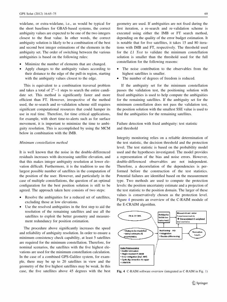
Integrity monitoring relies on a reliable determination of
the test statistic, the decision threshold and the protection
level. The test statistic is based on the probability model
used and the hypotheses investigated. The model provides
a representation of the bias and noise errors. However,
double-differenced observables are not independent.
Therefore, a decorrelation of the dependencies is per-
formed before the construction of the test statistics.
Potential failures are identified based on the measurement
type. Two methods are used to compute the protection
levels: the position uncertainty estimate and a projection of
the test statistic to the position domain. The larger of these
values is conservatively chosen as the protection level.
Figure 4 presents an overview of the C-RAIM module of
the E-CRAIM algorithm.
Fig. 4 C-RAIM software overview (integrated as C-RAIM in Fig. 1)
GPS Solut (2012) 16:65–75 69
123
The test statistic is determined from measured data and
compared with the decision threshold to determine whether
a failure has occurred. The threshold is set such that the
probability of exceeding it under nominal conditions of the
test statistic distribution corresponds to the tolerable
probability of false alert. This threshold then defines the
minimum detectable bias (MDB) (Teunissen 1990), which
describes the smallest bias value in the observables that can
be detected for a given probability of missed detection.
The E-CRAIM algorithm is based on a combination of
different measurements:
• pseudorange
• single-frequency carrier phase (L1).
To eliminate receiver and satellite clock errors as well as
ephemeris errors, double-differencing with respect to a
static reference receiver is used. This introduces correla-
tions between measurements, which are however, mathe-
matical, and the test statistics are therefore constructed
such as to decorrelate those measurements:
Tq ¼
ffiffiffiffiffiffiffiffiffiffiffiffiffiffiffi
rTq Wqrq
n� 4
s
ð3Þ
TL1 ¼ffiffiffiffiffiffiffiffiffiffiffiffiffiffiffiffiffiffiffiffi
rTL1WL1rL1
n� 4
r
ð4Þ
where
• Tq is the pseudorange-measurement-based statistic.
• TL1 is the L1-measurement-based test statistic.
• r is the measurement residual given by rk ¼ yk � Hkxk
where y is the measurement vector; H the design matrix
and x the state (positioning) vector, where the sub-
scripts q and L1 indicate pseudorange and L1 carrier,
respectively.
• Wq and WL1 are the weight matrices accounting for the
covariance, the measurement noise and the correlations,
for the pseudorange and L1 carrier phase observables,
respectively.
• n is the number of satellites.
The chi-square distribution threshold Tn is determined
from the probability of false alert and the number of
degrees of freedom (DOF). Whether it is a central or
noncentral chi-square distribution depends on the absence
or the presence of a range bias error. The threshold T for
the test statistic is given by:
T ¼ r
ffiffiffiffiffiffiffiffiffiffiffi
Tn
n� 4
r
ð5Þ
where r is the standard deviation of the measurement
errors, dependent on the type of observables used, and is
obtained either from external integrity monitoring net-
works, such as the E-GBAS, or estimated at user level. If
the test statistic exceeds the threshold, the test statistic
value is taken as the threshold, reflecting the variability of
the MDB as a result of a change in the SSE. The MDB is
then recomputed for each value of the test statistic
obtained.
Protection levels
The PL is an upper bound that the position error must not
exceed without being detected for a given integrity risk.
The protection levels are computed under two hypotheses:
fault-free and biased measurements. In the first case, the
position uncertainty estimate is obtained from the covari-
ance matrix, projected to the position domain, multiplied
by the fault-free missed detection multiplier, similar to the
method currently proposed for CAT III landings (RTCA
2001). In the second case, the decision threshold of the test
statistic together with the allowed probability of missed
detection determines the MDB. The MDB is projected to
the position domain using the maximum of the ratios of the
position error to the test statistic of all satellites. The larger
of the protection levels is conservatively chosen. Details on
the PL calculation can be found in Ochieng et al. (2007)
and Schuster et al. (2008).
An accurate estimation of the uncertainties of the
observables is key to determining the PLs. Traditional
C-RAIM methods assume constant uncertainty values for a
given observable type, when external uncertainty monitors,
such as GBAS or E-GBAS, are not available. This is not
suitable for aviation applications due to the diversity of the
operational environments. Even in the presence of uncer-
tainty estimations from the reference receivers of an
E-GBAS network, the final estimation of the uncertainties
in the observables, and therefore the solution uncertainties,
need to be carried out at user level. Therefore, two methods
are used, as described in Bai (2008). A conservative esti-
mation takes the maximum uncertainty value from the two
methods as the final estimation.
Analysis and results
The algorithms are subject to a detailed performance
characterization, taking into account operational specifici-
ties, and potential decorrelations between the reference
station and aircraft.
Comparison of different ambiguity search
and validation techniques
Both real and simulated static GNSS data are processed
with the HP-NAV software on an epoch-by-epoch basis to
determine the accuracy and integrity performance of the
70 GPS Solut (2012) 16:65–75
123
enhanced ambiguity resolution method and E-CRAIM
algorithm. A data set from the Ordnance Survey (OS)
station NOTT (Nottingham) and from another receiver at
the University of Nottingham are used, with a baseline
length of 2.5 km and time period of 1 h (3,600 epochs,
from 06:00:00 to 06:59:59 on 29 Jun 2006) to compare the
performances of the various ambiguity resolution and
validation techniques. The C/A code observable on L1 and
carrier phase observables on L1 and L2 are used.
Table 1 compares the performances of the FT and IMB re-
search schemes, using all available satellites pairs in the
ambiguity search. ‘‘Average Knots’’ refers to the average
number of knots searched in 3,600 epochs. ‘‘Reported Fail-
ure’’ is the number of epochs for which the ambiguity is
considered as not resolved, as determined by the ambiguity
validation module. ‘‘Actual Failure’’ corresponds to the
number of epochs for which the correct ambiguity is not
included in the re-search space. ‘‘MD’’ (missed detection) is
the number of epochs for which the wrong ambiguities pass
the validation test. As expected, the FT method results in the
lowest failure rate, because it searches the entire ambiguity
space. However, this method is also computationally inten-
sive, with up to 2187 knots searched for a single epoch. The
IMB method is significantly more efficient, but the failure rate
is relatively poor and insufficient for practical applications.
Table 2 shows the performance of the MCM with the
IMB search scheme. The statistical data for both the min-
imum constellation and the full constellation, after the
ambiguities for the minimum constellation have been
solved, are shown. Compared to the results in the absence
of using MCM, the performance is dramatically enhanced.
The performance is such that it is adequate for real-time
applications, with a very high success rate for short base-
lines, of the order of 99.94% for the data set analyzed.
Accuracy performance characterization
Simulation and field trials are used here to characterize the
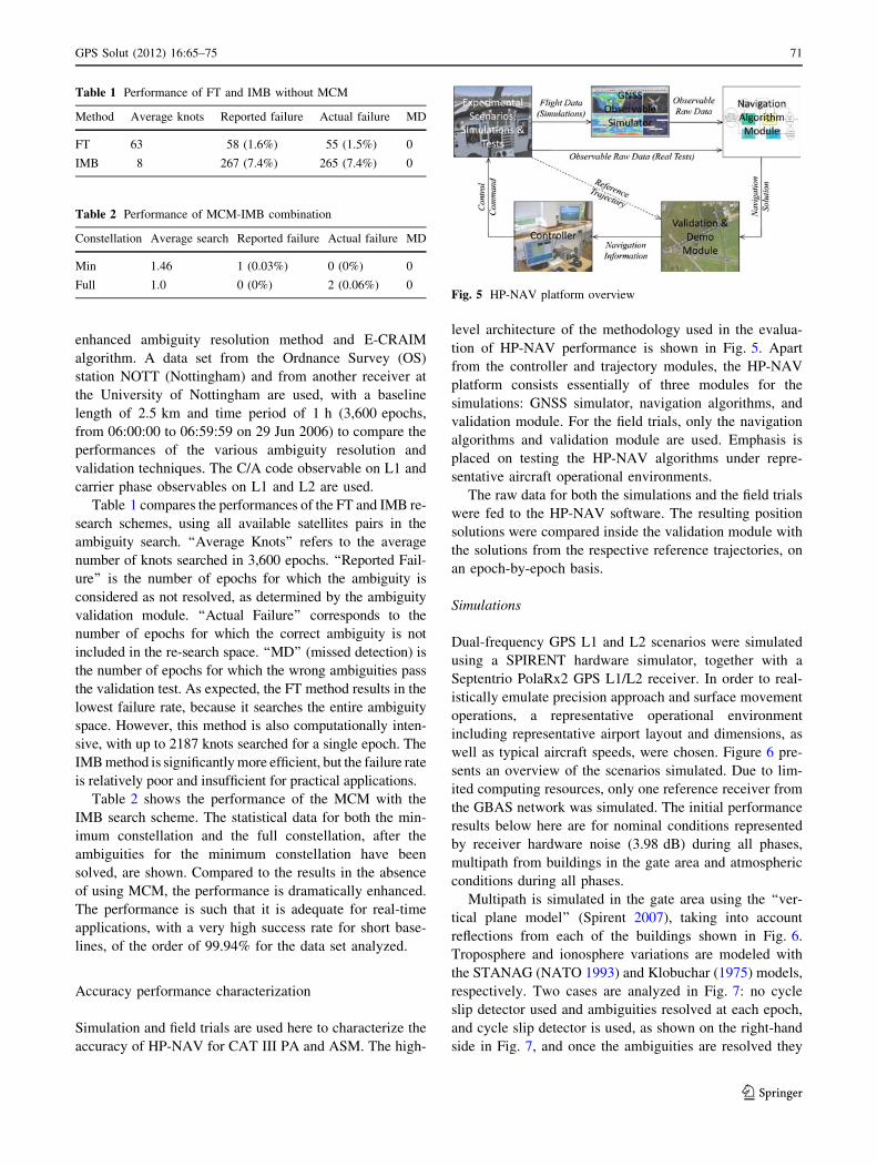
accuracy of HP-NAV for CAT III PA and ASM. The high-
level architecture of the methodology used in the evalua-
tion of HP-NAV performance is shown in Fig. 5. Apart
from the controller and trajectory modules, the HP-NAV
platform consists essentially of three modules for the
simulations: GNSS simulator, navigation algorithms, and
validation module. For the field trials, only the navigation
algorithms and validation module are used. Emphasis is
placed on testing the HP-NAV algorithms under repre-
sentative aircraft operational environments.
The raw data for both the simulations and the field trials
were fed to the HP-NAV software. The resulting position
solutions were compared inside the validation module with
the solutions from the respective reference trajectories, on
an epoch-by-epoch basis.
Simulations
Dual-frequency GPS L1 and L2 scenarios were simulated
using a SPIRENT hardware simulator, together with a
Septentrio PolaRx2 GPS L1/L2 receiver. In order to real-
istically emulate precision approach and surface movement
operations, a representative operational environment
including representative airport layout and dimensions, as
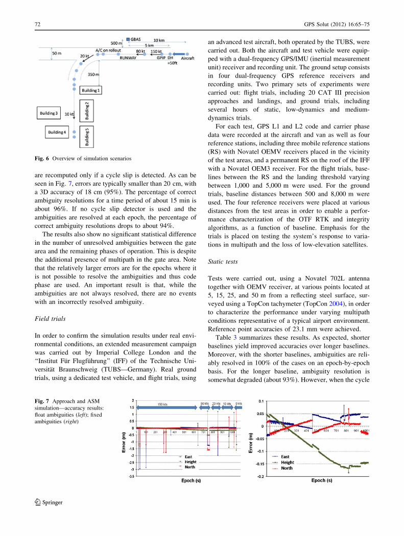
well as typical aircraft speeds, were chosen. Figure 6 pre-
sents an overview of the scenarios simulated. Due to lim-
ited computing resources, only one reference receiver from
the GBAS network was simulated. The initial performance
results below here are for nominal conditions represented
by receiver hardware noise (3.98 dB) during all phases,
multipath from buildings in the gate area and atmospheric
conditions during all phases.
Multipath is simulated in the gate area using the ‘‘ver-
tical plane model’’ (Spirent 2007), taking into account
reflections from each of the buildings shown in Fig. 6.
Troposphere and ionosphere variations are modeled with
the STANAG (NATO 1993) and Klobuchar (1975) models,
respectively. Two cases are analyzed in Fig. 7: no cycle
slip detector used and ambiguities resolved at each epoch,
and cycle slip detector is used, as shown on the right-hand
side in Fig. 7, and once the ambiguities are resolved they
Table 1 Performance of FT and IMB without MCM
Method Average knots Reported failure Actual failure MD
FT 63 58 (1.6%) 55 (1.5%) 0
IMB 8 267 (7.4%) 265 (7.4%) 0
Table 2 Performance of MCM-IMB combination
Constellation Average search Reported failure Actual failure MD
Min 1.46 1 (0.03%) 0 (0%) 0
Full 1.0 0 (0%) 2 (0.06%) 0Fig. 5 HP-NAV platform overview
GPS Solut (2012) 16:65–75 71
123
are recomputed only if a cycle slip is detected. As can be
seen in Fig. 7, errors are typically smaller than 20 cm, with
a 3D accuracy of 18 cm (95%). The percentage of correct
ambiguity resolutions for a time period of about 15 min is
about 96%. If no cycle slip detector is used and the
ambiguities are resolved at each epoch, the percentage of
correct ambiguity resolutions drops to about 94%.
The results also show no significant statistical difference
in the number of unresolved ambiguities between the gate
area and the remaining phases of operation. This is despite
the additional presence of multipath in the gate area. Note
that the relatively larger errors are for the epochs where it
is not possible to resolve the ambiguities and thus code
phase are used. An important result is that, while the
ambiguities are not always resolved, there are no events
with an incorrectly resolved ambiguity.
Field trials
In order to confirm the simulation results under real envi-
ronmental conditions, an extended measurement campaign
was carried out by Imperial College London and the
‘‘Institut Fur Flugfuhrung’’ (IFF) of the Technische Uni-
versitat Braunschweig (TUBS—Germany). Real ground
trials, using a dedicated test vehicle, and flight trials, using
an advanced test aircraft, both operated by the TUBS, were
carried out. Both the aircraft and test vehicle were equip-
ped with a dual-frequency GPS/IMU (inertial measurement
unit) receiver and recording unit. The ground setup consists
in four dual-frequency GPS reference receivers and
recording units. Two primary sets of experiments were
carried out: flight trials, including 20 CAT III precision
approaches and landings, and ground trials, including
several hours of static, low-dynamics and medium-
dynamics trials.
For each test, GPS L1 and L2 code and carrier phase
data were recorded at the aircraft and van as well as four
reference stations, including three mobile reference stations
(RS) with Novatel OEMV receivers placed in the vicinity
of the test areas, and a permanent RS on the roof of the IFF
with a Novatel OEM3 receiver. For the flight trials, base-
lines between the RS and the landing threshold varying
between 1,000 and 5,000 m were used. For the ground
trials, baseline distances between 500 and 8,000 m were
used. The four reference receivers were placed at various
distances from the test areas in order to enable a perfor-
mance characterization of the OTF RTK and integrity
algorithms, as a function of baseline. Emphasis for the
trials is placed on testing the system’s response to varia-
tions in multipath and the loss of low-elevation satellites.
Static tests
Tests were carried out, using a Novatel 702L antenna
together with OEMV receiver, at various points located at
5, 15, 25, and 50 m from a reflecting steel surface, sur-
veyed using a TopCon tachymeter (TopCon 2004), in order
to characterize the performance under varying multipath
conditions representative of a typical airport environment.
Reference point accuracies of 23.1 mm were achieved.
Table 3 summarizes these results. As expected, shorter
baselines yield improved accuracies over longer baselines.
Moreover, with the shorter baselines, ambiguities are reli-
ably resolved in 100% of the cases on an epoch-by-epoch
basis. For the longer baseline, ambiguity resolution is
somewhat degraded (about 93%). However, when the cycle
Fig. 6 Overview of simulation scenarios
Fig. 7 Approach and ASM
simulation—accuracy results:
float ambiguities (left); fixed
ambiguities (right)
72 GPS Solut (2012) 16:65–75
123

slip detector is used, the performance is improved to the
level where all ambiguities are successfully resolved.
Protection levels were typically at the level of about 0.5 m,
significantly smaller than the 1.4 m alert limit (AL)
requirement for ASM during the static trials at 50 m from
the steel hangar doors. However, at 5 m from the hangars,
the protection levels increase above the 1.4 m AL due to
satellite masking and the resulting relatively poor satellite
geometry.
Low-dynamics tests
An experimental vehicle fitted with a Novatel OEMV GPS
receiver and Novatel 532 antenna, as well as a Litef LLN-
G1 IMU, was used to make ten laps on a concrete surface
surrounded on three sides by trees and buildings, featuring
many chances for blockages of satellite visibility and
multipath. Two reference systems were used:
• a Leica TCR 805 totalstation with an automatic
tracking function;
• a secondary system coupling the OEMV with an IMU.
Figure 8 shows the test van with the totalstation in the
foreground. The IMU and Novatel antenna are fixed to the
roof of the van in a weatherproof enclosure. The prism for
the totalstation is located at the front of the roof of the test
van. A pattern featuring backwards passages was chosen
such that the reflector was permanently visible from the
totalstation.
Figure 9 gives an overview of the measurement results.
The shaded areas depict the motion of the van, while the
non-shaded areas correspond to the static periods. As
expected, the accuracy of the static phases of the low
dynamic data is very good, with a value of 0.090 m (95%),
despite the presence of strong multipath conditions. The
accuracy of the measurements of the dynamic portions of
the low-dynamics data is at 0.093 m (95%), very similar to
the static portions. This is as expected, since ambiguities
are resolved on an epoch-by-epoch basis. The protection
levels computed by the E-CRAIM software (Bai et al.
2008) were below 1.4 m, which is the alert limit for airport
surface movement, 100% of the time. Results from shorter
baselines showed no significant difference with respect to
the longer baseline under the nominal conditions encoun-
tered during these measurement trials. However, it is
anticipated that, in the presence of strong ionosphere
conditions, shorter baselines will provide improved per-
formance over the longer baselines. This is the subject of
further research.
Flight tests
The flight trials were carried out using an advanced test
aircraft, a Dornier Do-128-6 owned by the IFF. Using
standard approach procedures, 20 CAT III precision
approaches were taken. The distance flown along the
approach is approximately eight nautical miles and the
Fig. 9 Low-dynamics data results (8,000-m baseline)
Fig. 8 Left: Experimental van and totalstation; Right: Van trajectories (� Google Earth and AeroWest)
Table 3 Static GPS L1/L2 measurements: steel hangar doors at
various distances from the receiver
Distance to steel hangar
doors (m)
Baseline
(m)
Accuracy—m
(95%)
PL \ 1.4 m
(%)
5 1,400 0.048 74
7,000 0.051 74
50 1,400 0.036 100
7,000 0.070 100
GPS Solut (2012) 16:65–75 73
123
approach was aborted on reaching a height of about 5
meters above the runway.
The reference trajectory for the flight trials used a
combination of a coupled IMU/GPS system, featuring an
iMAR iTRACE RF-200 IMU and a Novatel OEMV,
together with a laser tracker, manufactured by IBEO and
operated by NLR personnel, using a special reflector fitted
to the aircraft.
A posteriori analyses suggest that the reference system
accuracy during the CAT III precision approaches was of
the order of 0.7 m. Given expected positioning accuracies
of the HP-NAV software during the CAT III precision
approach of the order of 0.20 m, as obtained with the
simulations, a detailed validation of the HP-NAV software
was not possible. However, analyses indicate that there is
good agreement between the positions extracted from the
reference trajectory and the positions computed by the HP-
NAV software all along the approach. Further work is
required to improve the accuracy of the reference trajectory.
E-CRAIM position-domain performance
characterization
In order to determine the suitability of the E-CRAIM
algorithm for surface movement, its performance was
analyzed under varying fault scenarios. Initially, the
emphasis was placed on the detection of cycle slips for the
cases where the preprocessor was unable to identify and
correct for the cycle slip, and on the detection of localized
ionosphere anomalies that are undetectable with the
E-GBAS architecture.
Data were simulated with the GPS Simulation Software
(GSS) developed at Imperial, using a standard GPS
24-satellite constellation, making use of recorded ephem-
eris on June 29, 2006. A baseline length of 5 km between
the reference and aircraft was chosen. The results shown
below are for static aircraft only. Realistic multipath on
both carrier phase observables, with variations up to one
quarter of the wavelength, which is the theoretical
maximum for carrier phase, was assumed. Residuals from
E-GBAS under nominal conditions, i.e., assuming that
E-GBAS monitors have not detected any ionosphere
anomaly, were added to all observables. The assumption is
made that cycle slips were not detected, and hence not
fixed, by the preprocessor.
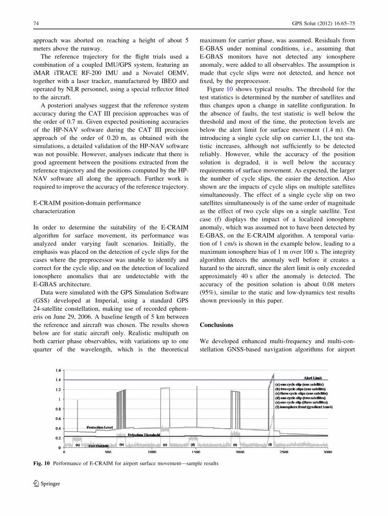
Figure 10 shows typical results. The threshold for the
test statistics is determined by the number of satellites and
thus changes upon a change in satellite configuration. In
the absence of faults, the test statistic is well below the
threshold and most of the time, the protection levels are
below the alert limit for surface movement (1.4 m). On
introducing a single cycle slip on carrier L1, the test sta-
tistic increases, although not sufficiently to be detected
reliably. However, while the accuracy of the position
solution is degraded, it is well below the accuracy
requirements of surface movement. As expected, the larger
the number of cycle slips, the easier the detection. Also
shown are the impacts of cycle slips on multiple satellites
simultaneously. The effect of a single cycle slip on two
satellites simultaneously is of the same order of magnitude
as the effect of two cycle slips on a single satellite. Test
case (f) displays the impact of a localized ionosphere
anomaly, which was assumed not to have been detected by
E-GBAS, on the E-CRAIM algorithm. A temporal varia-
tion of 1 cm/s is shown in the example below, leading to a
maximum ionosphere bias of 1 m over 100 s. The integrity
algorithm detects the anomaly well before it creates a
hazard to the aircraft, since the alert limit is only exceeded
approximately 40 s after the anomaly is detected. The
accuracy of the position solution is about 0.08 meters
(95%), similar to the static and low-dynamics test results
shown previously in this paper.
Conclusions
We developed enhanced multi-frequency and multi-con-
stellation GNSS-based navigation algorithms for airport
Fig. 10 Performance of E-CRAIM for airport surface movement—sample results
74 GPS Solut (2012) 16:65–75
123
surface movement, with focus on the integrity function
E-CRAIM. The chosen method of combining LAMBDA
with MCAR was shown to significantly enhance the
probability of correct ambiguity resolution. A new ambi-
guity validation method using a combination of the F-test
for the L1 observables and the IA method for the widelane
and extra-widelane observables was shown to improve the
speed at which the ambiguities are validated. One of the
novelties in this paper is the introduction of a re-search and
re-validation method for those scenarios where the ambi-
guity could not be fixed on the first iteration. The IMB
scheme was optimized in terms of efficiency for real-time
short baseline applications on the airport environment. In
order to reduce the high computational requirements, a
two-step procedure using the MCM is proposed. This was
shown to result in a significantly higher percentage of
correct ambiguity resolutions with a significantly higher
efficiency. A novelty of the E-CRAIM algorithm is that it
uses a multi-step approach to enhance integrity perfor-
mance. The use of external integrity information, such as
from the E-GBAS, improves the overall E-CRAIM per-
formance, compared to traditional C-RAIM.
The algorithms were shown to be robust against large
noise levels, as well as cycle slip conditions undetected by
the preprocessor and ionosphere fronts undetected by the
E-GBAS. The combined algorithm was shown to be robust
and at a level of performance where it has the potential to
meet the airport surface movement navigation system
performance requirements.
Acknowledgments The authors would like to thank the students
and members of the Institute of Flight Guidance at the Technical
University of Braunschweig for their support of the flight trials.
Aerodata, Braunschweig, are gratefully acknowledged for providing
the laser tracker. Many thanks go to Harald de Haan (NLR) for the
operation of the laser tracker and to Holmer Denks (DLR) for car-
rying out the initial simulations.
References
Bai J (2008) Robust navigation algorithms for aircraft precision
approach, landing and surface movement using global navigation
satellite systems, PhD thesis, Imperial College London
Bai J, Schuster W, Ochieng W (2008) Advanced navigation
algorithms for airport surface movement—developments &
performance. ENC GNSS, Toulouse
Boeing (2005) Determining the vertical alert requirements for a level
of GBAS service that is appropriate to support Cat II/III
operations, Boeing report vol IV
Feng S, Ochieng W, Moore T, Hill C, Hide C (2008) Carrier phase
based integrity monitoring for high accuracy positioning, GPS
Solut 13(1):13–22
Klobuchar JA (1975) A first-order, worldwide, ionospheric time-delay
algorithm, air force surveys in geophysics, No. 324
NATO (North Atlantic Treaty Organization) (1993) Standardization
agreement (STANAG) Doc. 4294 EL (Edition 1), Appendix 6 to
Annex A, pp. A-6–34–A-6–37. North Atlantic Treaty Organiza-
tion, Brussels
Ochieng W, Feng S et al. (2007) User level integrity monitoring and
quality control for seamless positioning in all conditions and
environments. ION GNSS, Fort Worth
RTCA (2001) Minimum operational performance standards for GPS
local area augmentation system airborne equipment, RTCA-
DO253A
Schuster W, Ochieng W (2011a) Airport surface movement—critical
analysis of navigation system performance requirements, J
Navig 64(2):281–294
Schuster W, Ochieng W (2011b) Novel integrity concept for CAT III
precision approaches and taxiing: extended GBAS (E-GBAS), J
Navig 64(4)
Schuster W, Bai J, Feng S, Ochieng W (2007) Airport surface
movement—performance requirements, architecture consider-
ations & integrity algorithms. ION GNSS, Fort Worth
Schuster W et al. (2008) High accuracy navigation study report,
ANASTASIA EC deliverable D3232
Schuster et al. (2009) Key technology operational performance
analysis final report, ANASTASIA EC deliverable D3.4
SPIRENT (2007) SimGEN software user manual, DGP00686AAA
Issue 1–22
Teunissen PJG (1990) An integrity and quality control procedure for
use in multi sensor integration, ION-GPS, 513–522
Teunissen PJG (1995) The least-squares ambiguity decorrelation
adjustment: a method for fast GPS integer ambiguity estimation.
J Geodesy 70:65–82
Teunissen PJG (1999) An optimality property of the integer least-
squares estimator. J Geodesy 73:587–593
Teunissen PJG (2001) GNSS ambiguity bootstrapping: theory and
application. In: Proceedings of KIS2001, pp 246–254
TOPCON (2004) DT-200 series—digital (Laser) theodolites bro-
chure, TOPCON Europe, Capelle a/d Ijssel, The Netherlands,
October 2004
Verhagen S, Teunissen PJG (2006) New global navigation satellite
system ambiguity resolution method compared to existing
approaches. J Guid Control Dynamics 29(4):981–991
Author Biography
Wolfgang Schuster is a senior researcher in Positioning and
Navigation Systems (PNS) and Air Traffic Management (ATM), at
the Centre for Transport Studies in the Department of Civil and
Environmental Engineering at Imperial College London. His work
focuses on the development of methodologies and technologies to
improve the efficiency and safety of air transport and to minimise
aviation’s impacts on the environment. In regard to PNS, his main
contributions are in the domain of intelligent integrity monitoring,
specifically for precision landings and airport surface movement. In
the ATM domain, his expertise is in the development of advanced
collision risk models, high-performance trajectory prediction and
efficient conflict detection and resolution tools, with emphasis on
modelling uncertainties. Dr. Schuster holds a DPhil in High-Energy
Physics from the University of Oxford (UK) and a commercial pilot
license.
GPS Solut (2012) 16:65–75 75
123


![Specification of Crypto Driver - AUTOSAR...[7] Glossary AUTOSAR_TR_Glossary [8] Specification of the 3GPP Confidentiality and Integrity Algorithms 128-EEA3 & 128-EIA3: Document 1:](https://img.dokumen.tips/doc/110x75/60e236af67ad34738d28fe74/specification-of-crypto-driver-autosar-7-glossary-autosartrglossary-8.jpg)