Embed Size (px)
Citation preview
Chapter 6
Integrating RFID with IP Host Identities
Steffen Elmstrøm Holst Jensen andRune Hylsberg Jacobsen
Additional information is available at the end of the chapter
http://dx.doi.org/10.5772/53525
1. Introduction
The “Internet of Things” semantically means ‘‘a world-wide network of interconnected ob‐jects uniquely addressable, based on standard communication protocols” [1]. The vision de‐scribes a world that enables physical objects to act as nodes in a networked physical world[2]. The terms ‘‘Internet of Things” can be attributed to The Auto-ID Labs, a world-wide net‐work of academic research laboratories in the field of networked RFID and emerging sens‐ing technologies [2]. Together with EPCglobal®, these institutions have been architecting theInternet of Thing since their establishment. Their focus has primarily been on the develop‐ment of the Electronic Product Code™ (EPC) to support the wide-spread use of RFID inmodern, global trading networks, and to create an industry-driven set of global standardsfor the EPCglobal Network.
EPCglobal Network was created for “traditional” low-cost tags [3]. The main functionali‐ty of the EPCglobal Network is to provide data assigned to a specific tag, so that eachRFID read event can be stored in a database and applications can be built on this data.Since tags were not originally considered to carry or compute additional data, the EPC‐global Network does not traditionally provide a mechanism to address remote tags fromnetworked applications.
The data flow in these networks works from tags via readers to a couple of networked serv‐ers. Passive, low-cost RFID tags are widely available and the EPCglobal Network was de‐fined to support open-loop supply chain applications. Basically, this is accomplished byallowing servers to communicate over the Internet. Although RFID technology is quite ac‐cepted in closed-loop applications, the evolution towards open-loop systems using the EPC‐global Network with distributed databases did not take place as predicted due to problemsin the access control layer of such systems.
© 2013 Jensen and Jacobsen; licensee InTech. This is an open access article distributed under the terms of theCreative Commons Attribution License (http://creativecommons.org/licenses/by/3.0), which permitsunrestricted use, distribution, and reproduction in any medium, provided the original work is properly cited.

RFID-sensor networks are an emerging part of the Internet of Things [5]. These devices com‐bine sensing capabilities with an RFID interface that allow the retrieval of sensed data. Infact, they can cooperate with RFID systems to better track the status of things e.g., their loca‐tion, temperature, movements, etc. A sensor-enabled RFID tag (also known as sensor-tags)is an RFID tag which contains one or more sensors to monitor some physical parameter(e.g., temperature) but also contains the same identification function as a “normal” RFID tagdoes. This kind of sensor tag may fall into class 2, class 3 or class 4 in EPCglobal's tag classi‐fication [3]. A fully passive, class 2 sensor-tag can measure physical parameters, i.e., use sen‐sors, only when powered by a reader. In contrast, class 3 tags are battery assisted. They canwork independently of the reader and can be suitable for RFID-sensor networks.
In this chapter, we will discuss different ways to achieve the Internet of Things vision byinternetworking passive RFID tags over IPv6. The chapter is organized as follows: Section 2presents related works and discusses the novelty of the work presented here. Section 3 intro‐duces the key technologies for the convergence of RFID and Internet namespaces and toprovide an address mapping needed to internetwork passive RFID tags. In Section 4, somecommon examples of RFID usage are given and discussed in the context of globally net‐worked tags. Subsequently, Section 5 introduces a testbed built to study the interconnectionof passive RFID tags over IPv6. The different strategies that can be used for integrating RFIDwith IPv6 are discussed in Section 6 and this discussion is followed by mobility considera‐tions in Section 7. Finally, Section 8 concludes the discussion and outlines anticipated futurework in this area.
2. Related works
Most objects in our surrounding are not equipped with microprocessors and hence cannotattach to a computer network. However, these objects can be equipped with passive, low-cost RFID tags either as tags integrated or adhesively stuck to the object and hereby providea mean of communications. Dominikus et al. [14] has suggested a way to integrate passiveRFID systems into the Internet of Things, by using readers that function as IPv6 routers. Intheir work, an IPv6 addressing scheme that map tag IDs to network addresses was defined.Furthermore, the mobility problem, which arises when tags physically moves around, wasinvestigated and the use of Mobile IPv6 (MIPv6) to cope with tag mobility was suggested. Incontrast to the work presented by Dominikus et al. [14], this chapter opens the discussion onthe proper formatting of the IPv6 addressing by introducing cryptographic hashing techni‐ques as well as the possibility of separating identity and location information when formingan IPv6 address. The use of hashing techniques to construct an IPv6 address from an EPC,as opposed by using a compressed EPC format [14], eases practical implementations and al‐lows the use of the same mapping scheme for all EPC types.
An alternative approach is to provide the tags themselves with the IPv6 protocol stack, mak‐ing them able to use IPv6 communication over the Internet whenever close to a reader. Thisrequires several changes to the design of existing tags. In this case, the tags do all the work
Radio Frequency Identification from System to Applications112
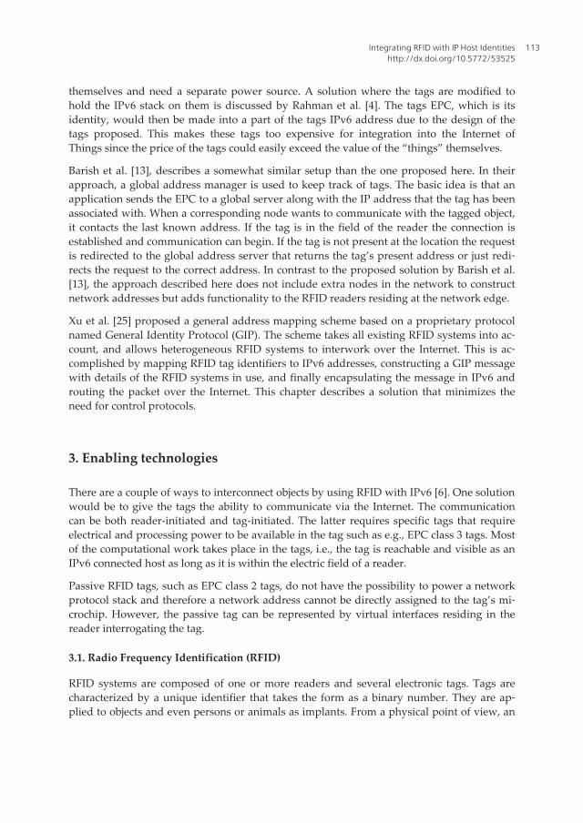
themselves and need a separate power source. A solution where the tags are modified tohold the IPv6 stack on them is discussed by Rahman et al. [4]. The tags EPC, which is itsidentity, would then be made into a part of the tags IPv6 address due to the design of thetags proposed. This makes these tags too expensive for integration into the Internet ofThings since the price of the tags could easily exceed the value of the “things” themselves.
Barish et al. [13], describes a somewhat similar setup than the one proposed here. In theirapproach, a global address manager is used to keep track of tags. The basic idea is that anapplication sends the EPC to a global server along with the IP address that the tag has beenassociated with. When a corresponding node wants to communicate with the tagged object,it contacts the last known address. If the tag is in the field of the reader the connection isestablished and communication can begin. If the tag is not present at the location the requestis redirected to the global address server that returns the tag’s present address or just redi‐rects the request to the correct address. In contrast to the proposed solution by Barish et al.[13], the approach described here does not include extra nodes in the network to constructnetwork addresses but adds functionality to the RFID readers residing at the network edge.
Xu et al. [25] proposed a general address mapping scheme based on a proprietary protocolnamed General Identity Protocol (GIP). The scheme takes all existing RFID systems into ac‐count, and allows heterogeneous RFID systems to interwork over the Internet. This is ac‐complished by mapping RFID tag identifiers to IPv6 addresses, constructing a GIP messagewith details of the RFID systems in use, and finally encapsulating the message in IPv6 androuting the packet over the Internet. This chapter describes a solution that minimizes theneed for control protocols.
3. Enabling technologies
There are a couple of ways to interconnect objects by using RFID with IPv6 [6]. One solutionwould be to give the tags the ability to communicate via the Internet. The communicationcan be both reader-initiated and tag-initiated. The latter requires specific tags that requireelectrical and processing power to be available in the tag such as e.g., EPC class 3 tags. Mostof the computational work takes place in the tags, i.e., the tag is reachable and visible as anIPv6 connected host as long as it is within the electric field of a reader.
Passive RFID tags, such as EPC class 2 tags, do not have the possibility to power a networkprotocol stack and therefore a network address cannot be directly assigned to the tag’s mi‐crochip. However, the passive tag can be represented by virtual interfaces residing in thereader interrogating the tag.
3.1. Radio Frequency Identification (RFID)
RFID systems are composed of one or more readers and several electronic tags. Tags arecharacterized by a unique identifier that takes the form as a binary number. They are ap‐plied to objects and even persons or animals as implants. From a physical point of view, an
Integrating RFID with IP Host Identitieshttp://dx.doi.org/10.5772/53525
113
RFID tag is a small microchip attached to an antenna that is used for both receiving thereader signal and transmitting the tag ID. The dimensions of each tag can be very small withtag dimensions down to 0.05 mm x 0.05 mm with a thickness of 0.005 mm [7]. There aremore than 60 tag manufacturers world-wide [8].
RFID tags will act as electronic identification for physical objects to which they are linked. Inthe Internet of Things, all objects, virtual as well as physical, are interconnected and reacha‐ble via for example IPv6 in combination with RFID technology [6]. Essentially, the tag con‐nects to physical objects that we want to authenticate and track when they come in contactwith readers. A reader can read or modify tag’s information. The back-end database keepsinformation related to different tags/readers.
For reader-initiated communication the reader triggers the tag’s transmission by generatingan appropriate signal, which represents a query for the possible presence of tags in the sur‐rounding area and for the reception of their identification codes (IDs).
Active tags come with a power source that can drive a microprocessor (or microcontroller).Furthermore, it allows a stronger electromagnetic field to be generated in response to an in‐coming RFID air protocol message and larger read distances can be achieved. More ad‐vanced active tags or sensor-tags may run additional software and can be equipped withcommunication software such as an IP protocol stack [9].
In contrast, passive tags rely on the incoming electromagnetic field from the reader topower the circuit and to deliver power to drive the response to an interrogating request.These devices do not run communication software and cannot be actively involved in aprotocol message exchange. To communicate with these devices there is a need for soft‐ware agents to act on their behalf.
RFID tags can only be “online” when they are in the electric field of a reader field. For highvelocity applications, where tags only remain certain seconds in a reader field, the proposedapproach of networking these tags is not applicable.
3.2. RFID namespaces
Essentially, RFID comes with two namespace to be used with RFID applications: the EPCaddresses and the Object Name Service (ONS). A namespace can represent objects as well asconcepts and may be generalized as a container for a set of identifiers (names). The EPC isan identifier based on the standards established by EPCglobal® [10]. It is designed to allowthe automatic identification of objects anywhere. EPC defines three layers of identity: thepure identity, the encoding layer identity and the physical realization of an encoding. TheEPC tag data standard [10] identify how existing coding systems such as the GS1 family co‐des for serialized human readable representations e.g. GTIN, GCN, SSCC, GRAI, GIAI,GSRM, GDTI and a small number of other identities should be embedded within the EPC.
A canonical representation of an EPC is the pure identity Uniform Resource Indicator (URI)representation, which is intended for communicating and storing EPC in information sys‐tems, databases and applications. The purpose is to insulate EPCs from knowledge about
Radio Frequency Identification from System to Applications114

the physical nature of the tag, so that although 64-bit tags may differ from 96-bit tags in thechoice of binary header values and in the number of bits allocated to each element or fieldwithin the EPC, the pure identity URI format does not require the information system toknow about these details. Hence, the pure identity URI can be regarded as a pure identifier[10]. Tags are identified by URIs such as e.g., urn:epc:id:sgtin:0523141.000024.120 that com‐prise both tag number and associated coding scheme.
Encoding is the process of translating the pure identity EPC into a specific instantiation in‐corporated into tags for a specific purpose. During the encoding process the URI informa‐tion is translated into a binary encoding that is stored in the tag. Subsequently, translatingbetween the different levels of representation can be accomplished in a consistent way.
Figure 1 shows the structure of the data layout of an EPC code for the Global Trade ItemNumber (GTIN) and Serialized Global Trade Item Number 96-bit (SGTIN-96) tag.
CRC EPC Password
Indicator digit
Company prefix
Check digit
Item reference
GTINIdentity structure
SGTIN-96Bit-level encoding
Company prefix
Indicator digit
Serial number
Item reference
Serial number
Figure 1. Tag data layout example.
EPC generation 1 standards, i.e., class 0 and class 1 tags, use a Cyclic Redundancy Check(CRC) to verify data integrity and a password as a “kill code” to disable the tags. The pass‐word must never be transmitted under any circumstances [3]. The Item reference identifies aclass of objects to be tagged and it allows the grouping of items. The Serial number identifiesan instance of a particular item. Company prefixes (also known as General Manager Num‐bers) point to the organization responsible for the subsequent partition. Finally, Indicator dig‐its are used to specify length, type, structure, version, and generation of the EPC. This latterpart is further used to guarantee uniqueness in the EPC namespace. For the GTIN encodinga Check digit is used.
Since the EPC is the only required data stored on a tag, it must be used as a “pointer” to findadditional data about an object to which it attaches. This additional data should be stored ona server connected to the enterprise network or to the Internet. The server is identified via alook-up system which is called ONS.
Integrating RFID with IP Host Identitieshttp://dx.doi.org/10.5772/53525
115

ONS acts as a directory service for organizations wishing to look up product numbers (alsoknown as EPC numbers) on the Internet. The ONS is operated as part of the EPCglobal Net‐work. It is based on the well-known DNS service and it realizes the link between EPC num‐bers and EPC Information Services (EPCIS) as illustrated in Figure 2. When an RFID readerreads a tag, the EPC is passed to a middleware which then looks the EPC up either on thelocal machine, or enquires ONS through the Internet.
Tag
Reader
Local system
URI conversion
ONS resolver
EPCIS server
InternetONS/DNS server
PML files
Figure 2. The Object Name System (ONS). Adapted from [11].
The ONS resolution process takes the EPC code and returns network location(s) where in‐formation resides, i.e., the EPCIS server, which typically holds web pages with informationabout tags. The Physical Markup Language (PML), based on XML technology, is intended tobe the standard in which information about tags should be written.
In contrast, the DNS of the Internet will handle many more requests in the future. Therefore,enterprises will likely maintain ONS servers locally, which will store information for quickretrieval. Hence, a manufacturer may store ONS data from its current suppliers on its ownnetwork, rather than pulling the information off a Web site every time a shipment arrives atthe assembly plant.
3.3. Internet namespaces
There are two principal namespaces in use in the Internet: IP addresses and domain names.Domain names provide hierarchically assigned names for some computing platforms andsome services. Each level in the hierarchy is delegated from the level above. Email, Hyper‐text Transfer Protocol (HTTP), and Session Initiation Protocol (SIP) addresses all referencedomain names to mention its most wide-spread use.
Radio Frequency Identification from System to Applications116

On the network layer, IP addresses are used. IPv6 was introduced in the 90’ies due to theforeseen lack of globally unique IPv4 addresses, resulting in a protocol specification releasedin 1998 [17]. The IPv6 address is a 128-bit address that takes the form of a 64-bit networkprefix appended by a 64-bit host suffix/interface identifier. The network prefix is used forrouting purpose and determines the location of the host in the Internet. The host itself isidentified by an interface ID. Figure 3 shows the IPv6 address format and gives an exampleon how a 96-bit EPC can be mapped to a network address.
X X X X X X X X X X X X X X X X X X X X X X X X X X X X X X X X
128-bit IPv6 address
Network prefix Interface ID
16 bits
X X X X X X X XSerial Number
X X X X X XProduct
X X X X X X X XManufacturer
X XHeader
96-bits EPC structure (GID-96)
Figure 3. IPv6 address format compared to a 96-bit General Identifier (GID-96) EPC format. An ‘X’ indicates a group‐ing of 4 bits.
It can be observed form the figure that not all 96 bits of the EPC can be fitted within thehost suffix/interface identifier of an IPv6 address. Because of this deficiency, the imple‐menters of an RFID-to-IPv6 mapping scheme is faced with a number of design options.These options basically govern the strategy for the mapping and are the subject of ourdiscussion in Section 6.
3.4. Cryptographically generated addresses
Cryptographically Generated Addresses (CGAs) are IPv6 addresses for which the host suf‐fix/interface identifier is generated by computing a cryptographic one-way hash functionfrom a binary input such as e.g., a public key [27]. CGAs are intended to be globally uniquein a statistical sense but these may not necessarily be routable addresses at the IP layer [12].
The Overlay Routable Cryptographic Hash Identifiers (ORCHID) is a new, experimentalclass of identifiers based on CGAs. ORCHIDs have an IPv6-like address format and can beused with existing applications built on IPv6 [12]. These identifiers are intended to be usedas pure endpoint identifiers for applications and Application Programming Interfaces (APIs)and not as identifiers for network location. This is in contrast to the IPv6 address that usesthe 64-bit network prefix as locator [17].
While ORCHIDs use public cryptographic keys as input bit strings, it is possible to use thebinary EPC encoding instead. The algorithm to generate an ORCHID in an RFID context is
Integrating RFID with IP Host Identitieshttp://dx.doi.org/10.5772/53525
117

outlined below [12]. The algorithm takes a bitstring and some context identifier as inputs andproduces an ORCHID output that is formatted as an IPv6 address.
Input : =anybitstring (1)
HashInput : = ContextID | Input (2)
Hash : = Hash _ function( HashInput ) (3)
ORCHID : = Prefix | Encoden( Hash ) (4)
Concatenation of bitstrings is denoted '|'. The Input is a bitstring that is unique within a giv‐en context. The Context ID is a randomly generated value defining the expected usage con‐text for the particular ORCHID and the hash function to be used for generation of ORCHIDin this context. The purpose of a context ID is to be able to differentiate between various ex‐periments that share the ORCHID namespace. The Hash_function is a one-way hash functionto be used to generate ORCHIDs such as SHA1 [23] or MD5 [24]. SHA1 and MD5 produce a160-bit and a 128-bit output, respectively. Encoden is a function to extract an n-bit-long bit‐string from its argument. Finally, Prefix is an IPv6 network prefix.
To construct a CGA an input bitstring and context identifier are concatenated to form an in‐put datum, which is then fed to the cryptographic hash function. The result of the hash func‐tion is processed by an encoding function, resulting in an n-bit-long output. This value isprepended with the network prefix resulting in a 128-bit-long bitstring identifier that can beused for programming with the IPv6 API.
To create a CGA namespace for RFID tags the EPC of a tag and the network prefix assignedto the reader that interrogates the tag are used as input. Furthermore, an Encode64 functionis used to extract 64 bits from the hash. A key advantage of using hash values over the ac‐tual raw host identity resulting from the EPC is its fixed length. This makes protocol imple‐mentations easier and it alleviates the management of packet sizes. However, a claimeddrawback is that CGAs work one-way, meaning that it is not possible directly to create theoriginal identity from the hash.
A CGA can be globally unique or globally unique in a statistical sense. That is, the probabili‐ty of the same CGA being used to refer to different entities in the Internet must be sufficient‐ly low so that it can be ignored for all practical purposes. Even though CGA collisions areexpected to be extremely rare, collisions may still happen since it is possible that two differ‐ent input bitstrings within the same context may map to the same CGA. A second type ofcollision can happen if two input bitstrings, used in different contexts, map to the sameCGA. In this case, the main confusion is about which context to use. In order to preserve alow enough probability of collisions, it is required that applications ensure that distinct in‐put bitstrings are either unique or statistically unique within a given context. By adhering tothe EPCglobal standards, this requirement is fulfilled.
Radio Frequency Identification from System to Applications118

3.5. Host identities and host identity protocol
A host identity is an abstract concept assigned to a computing identity platform. In this sec‐tion, we will generalize this concept to cover thin compact platforms that can be equippedwith RFID tags. The discussion starts by introducing the host identities and the host identityprotocol [15][16].
The Host Identity Protocol (HIP) supports an architecture that decouples the transport layer(TCP, UDP, etc.) from the internetworking layer (IPv4 and IPv6) by using public/private keypairs, instead of IP addresses, as host identities [15][16]. The public keys are typically, butnot necessarily, self-generated. HIP introduces a new Host Identity (HI) namespace, basedon these public keys, from which end-point identifiers are taken. Host identifiers are used tobind to higher layer protocols instead of binding to IP addresses. A key benefit of this ap‐proach is that it is compatible with existing APIs such as the socket API. HIP uses existing IPaddressing and forwarding for locators and packet delivery, respectively.
Figure 4 illustrates the difference between binding of the logical entities service and end-points to an IP address (left side of figure). The service typically binds to the IP stack via thesocket API. By using the host identity abstraction of the HIP architecture, the service and theend-point bind to the host identity whereas the location is still anchored with the IP address.
End-point
Location IP address
SocketService
End-point
Location IP address
SocketService
Host identity
Figure 4. Illustration of the difference between the bindings of the logical entities. Adapted from [15].
There are two main representations of the host identity, the full Host Identifier (HI) and theHost Identity Tag (HIT). The HI is a public key and directly represents the identity. The HITis the operational representation of a host. It has a 128-bit long representation and is used inthe HIP payloads to index the corresponding state of the end hosts. By introducing an iden‐tity concept at the network layer, where every host is represented by an asymmetric key pairconsisting of a public and private key, it turns IP addresses into pure locators.
The proposed HI namespace fills an important gap between the IP and DNS namespa‐ces. A public key is used as the HIP Host Identity (HI), while the private key serves asproof of ownership of the public key. To seamlessly integrate HIP with protocols abovethe network layer, a 128-bit cryptographic hash of the HI, i.e., the HIT, was introducedto fit the IPv6 address space. The HIT is a statistically unique flat identifier. When HIP
Integrating RFID with IP Host Identitieshttp://dx.doi.org/10.5772/53525
119

is used, the transport layer binds to HITs. In this process it becomes unaware of the IPaddresses that are used for routing.
To be able to setup communication between peers that use HI, a light-weighted protocolexchange called the HIP Base Exchange has been specified. In Figure 5, the HIP Base Ex‐change is adapted to an RFID setup. The setup is somewhat similar to the one presentedby Urien et al. [11].
Since the deployed tags are passive, there is a need for a proxy to act on behalf of the tags inthe protocol exchange. The role of this proxy will be explained further in Section 5.
Rea
der a
pplic
atio
n Initiate 1: HITI, HITR
Protected channel
Tag 1
Tag 2
Tag n
Resp
onde
r /
prox
y
Initiate 2: HIT I, HITR, DH I, HII
Respond 1: HITR, HIT I, DHR, HIR
Respond 2: HITR, HIT IIniti
ator
Internet
Passive RFID tags
Back-end serversystem
Figure 5. HIP Base Exchange adapted to a RFID communication scenario. Adapted from [15].
The HIP Base Exchange is a four-way handshake between two hosts wanting to initiate com‐munication (see Figure 4). The Initiate 1 packet is the first packet sent in the handshake. It isan unencrypted and unsigned packet, meaning that the Initiator would like to talk HIP withthe Responder. The HIP packet contains the HIT of the Initiator (HITI) and the Responder(HITR). The responder’s IP address can be derived from the DNS. Respond 1 is sent as a replyto the Initiate 1 packet. Besides the HITI-HITR identity pair, it contains a cryptographic puz‐zle challenge, and Diffie-Hellman parameters (DHR) for the Diffie-Hellman key agreement.The Diffie–Hellman key exchange method allows two parties that have no prior knowledgeof each other to jointly establish a shared secret key over an insecure communication chan‐nel. Subsequently, the secret key can be used for encryption and integrity protection of thecommunication channel. The purpose of the HIP puzzle mechanism is to protect the Res‐ponder from denial-of-service attacks. The Initiate 2 packet returns the corresponding Diffie-Hellman parameter (DHI) to the Responder. It carries an encoded solution to the puzzle.
Radio Frequency Identification from System to Applications120

Upon reception of the Initiate 2 packet, the responder can now generate the keying material,and it is capable of using it in encryption and integrity protection algorithms. The Response2 packet completes the HIP Base Exchange. After the Base Exchange, there is no longer dif‐ference between the Initiator and Responder and data can securely be exchanged betweenthe communicating peers.
4. Use cases and application examples
RFID applications are numerous and far reaching [8]. The most interesting and widely usedapplications include those for security and access control, supply chain management, andthe tracking of important objects and personnel. This section outlines a number of common‐ly encountered use cases for RFID technology, and discusses these in the context of net‐worked RFID tags.
4.1. Access control
Access control systems are an important part of the security of government buildings, com‐panies, schools, residences and private areas and RFID technology has been widely adoptedin access control systems. These systems often use RFID identification cards based on theIEC/ISO 14443 [18], IEC/ISO 15693 [19], or IEC/ISO 18000 standards [20]. The identificationcards work much like a traditional key for unlocking doors or otherwise granting access.However, RFID technology does not provide authentication to the holder of the RFID card(or tag). Any unauthorized people holding an authorized RFID card could get access to se‐cured area. Therefore, RFID technology should be combined with other means of identifica‐tion such as e.g., face recognition to strengthen the security of the access control system.
By associating a passive RFID tag such as a key card with a globally unique IPv6 address wewill be able to use access control and security policy mechanisms with Internet technologiesto provide the desired access control applications. In this scenario a door locking mechanismwould be connected over the Internet resulting in a more open system architecture.
4.2. Supply chain management
Most supply chain applications involve the concept of inventory tracking. An example of aproposed use of RFID is to ensure safety in the supply chain [21].
To illustrate the potential of using network RFID tags with supply chain applications an ex‐ample taken from the Tag Data Standard v1.6 issue 2 [10]. The example text is quoted below:
“… a shipment arriving on a pallet may consist of a number of cases tagged with SGTIN identifiers and a returnablepallet identified by a GRAI identifier but also carrying an SSCC identifier to identify the shipment as a whole. If a por‐tal reader at a dock door simply returns a number of binary EPCs, it is helpful to have translation software which canautomatically detect which binary values correspond to which coding scheme, rather than requiring that the codingscheme and inbound representation are specified in addition to the input value.”
Integrating RFID with IP Host Identitieshttp://dx.doi.org/10.5772/53525
121

Each of the cases tagged will be given a unique IPv6 address when they enter the electricfield of a reader. This process involves the extracting of the essential bitstring of the SGTINidentifier for each case. Likewise, the returnable pallet and the shipment as a whole will begiven IPv6 addresses that can be built based on the GRAI and the SSCC, respectively. Byusing the assigned IPv6 unicast addresses it is possible to establish communication to indi‐vidual cases as well as the pallet. However, it may be of less interest to address individualcases at this point in the supply chain but rather to address the ensemble of cases. By intro‐ducing multicasting at the network layer it can be possible to communicate with groups ofcases on the pallet.
4.3. Object/asset tracking
Because moving objects can easily carry RFID tags, a common use is to track the movementof people and the information associated with them. By associating a particular tag’s EPCwith a global network address the task of tracking the object/asset become equivalent to lo‐cating a mobile host in the network. In general, this is a key challenge in mobility researchand several solutions have been proposed [22][26], and this will be the subject of our discus‐sion in Section 7. Another interesting use case can be applied to sensor-tags. When thesesensor-tags connect to a network sensor data can be retrieved from the tag.
5. Networked RFID testbed
To study the internetworking of objects with passive RFID tags, a simple testbed hasbeen built. The approach makes use of an RFID reader and an application that works asa proxy for the tags we wish to communicate with. The proxy is capable of making avirtual representation of the passive RFID tag on the Internet by creating a Virtual Net‐work Interface (VNI) with an IPv6 address that can be attributed to each tag that comeswithin the electric field of a reader. Hence, the tags do not terminate IPv6 traffic directlybut merely communicate with an entity which represents the tag (physical object) thatwe wish to communicate with.
The approach taken is software-oriented. The application runs as standalone but it can beembedded on the reader or it can be run on a computer local to the reader. The applicationreceives the EPC of a tag attached to a physical object via the reader. The application thencreates an IPv6 address from one of the mentioned methods. Hereafter, it is possible to routeIP traffic to the particular Internet end-point. This will in effect make the application act as aproxy that for example can keep the most recently read tags “online”. The solution gives aone-to-one mapping of physical objects to the virtual representations that are needed tocommunicate over the Internet.
Figure 6 illustrates the system implemented. In practice, the application host has a predeter‐mined number of Virtual Network Interfaces (VNIs) installed. These interfaces work as theonline virtual representation of the tag swiped at the reader. In other words, this is the inter‐face the outside world can contact. In the testbed, the network interfaces are virtualized in a
Radio Frequency Identification from System to Applications122

way similar to a loopback interface [17]. As the system works as a testbed the database ismerely there as a logging service. In the future, it is planned to use the database as founda‐tion for a local ONS. The corresponding node is there to illustrate possible communicationover the Internet.
Serial connection
IPv6
IPv6
Virtual Network Interfaces
representing the RFID tags swiped
RFID Reader
Application Host
Correspondingnode
Internet
Tag
Back-end database
Figure 6. Simple setup to give RFID tags virtual identification on the Internet. A RedBee RFID Reader v1.1 is used. Theapplication is built on the Microsoft®.NET connection software.
Figure 7 shows a state machine diagram for a single VNI resulting from a tag swiped in anaccess control application.
When the tag is swiped at the reader, the application host creates an IPv6 address by com‐bining the network prefix configured at the reader with the tags identity as illustrated by theExample in Table 1. In the initial state, the software is waiting for a TagSwipe event to occur.Subsequently, the interface is put online with the address constructed, and it is kept alive aslong the expiration time is greater than 0 (zero) seconds.
Tags are only reachable while they are within reader range. This makes it hard to communi‐cate with the real tag, simply because it is only reachable for a short duration of time. Whenthe tag’s attachment to the network is virtualized it is possible to set up an expiration value.This value effectively serves as the time the tags virtual representation on the network canbe reached.
The tag identity together with the constructed IPv6 address and a timestamp is stored on thedatabase. Table 1 shows an example of the steps taken to construct an IPv6 address from anEM4100 tag ID.
Integrating RFID with IP Host Identitieshttp://dx.doi.org/10.5772/53525
123

Waiting for TagSwipe
Interface alive while Expiration time > 0
Program started
TagSwipeevent
TagReswipe event. Expiration
time resetExpiration time
expired
Figure 7. State machine for the virtual interface resulting from a TagSwipe event at the reader.
Tag identity (Example with EM4100
tag)
5 decimal numbers
(40 bits)
127 0 58 207 19
Binary ID representation with left-
zero-padding
64 bits 0000 0000 0000 0000 0000 0000 0111 1111 0000 0000
0011 1010 1100 1111 0001 0011
Converted to hexadecimal 4 groups of 4 hex.
digits
0000 007f 003a cf13
Network prefix of RFID reader
(example)
4 groups of 4 hex.
digits
2001:16d8:dd92:aaaa::/64
Unicast IPv6 address associated
with the tag
8 groups of 4 hex.
digits
2001:16d8:dd92:aaaa::007f:003a:cf13/128
Table 1. Example of IPv6 network address construction from on EM4100 tag ID.
The application has no visual interface and all configurations must be done in software. Forexample, it is possible to use more than one virtual interface to represent the tags online.These interfaces need to be preinstalled, as already mentioned, and some parameters in theapplication need to be configured. Hereafter, it is possible to make use of at least 5 virtualinterfaces.
Although focus is on the assignment of IPv6 unicast addresses, tags can also be assigned tobecome member of multicast groups thereby facilitating one-to-many communication. As anexample an application may want to address all tags at a particular reader. Likewise, read‐ers can become members of multicast groups hereby enabling communication to all readers
Radio Frequency Identification from System to Applications124

in the multicast group e.g., a particular logical area. Details on how to operate an RFID inIPv6 multicast networks are beyond the scope of this chapter.
6. Strategies for interworking IPv6 with RFID tags
In this Section we will discuss different methods of mapping between an RFID namespaceand an Internet namespace.
6.1. Address mappings
The most simple approach to find IPv6 addresses for tags is the mapping of the tag ID to anIPv6 address, i.e., the bits from the ID are used to form the IP address [14]. As different pas‐sive RFID standards exist there is no common ID structure for tags. Even within standards,there are different types of IDs with different structures. This means, that a general conceptto map tag IDs to IPv6 addresses will not work.
Table 2 shows a list of some commonly encountered passive tags and their ID formats.
IC type Frequency band Memory Standards compliance
EM4100 series LF (125 KHz) 64 bits EM4100. Proprietary standard issued by EM
Microelectronics [28].
EM4450/4550 LF (125 KHz) 1024 bits EM4450/4550. Proprietary standard issued
by EM Microelectronics [29].
NXP Hitag family (Hitag 1,
Hitag 2, Hitag S, Hitag μ)
LF (125 KHz) 256 bit to 2048 bit IEC/ISO 18000-2 (Hitag μ) [20].
NXP Mifare family (Ultralight/
MF1S20/MF1S50/MF1S70/
DESFire EV1)
HF (13,56 MHz) 64 bytes to 4096
bytes
2K/4K/8K
ISO 14443A [18].
LEGIC Advant family (ATC128,
ATC256, ATC1024, ATC2048,
ATC4096)
HF (13,56 MHz) 128 bytes to 4096
bytes
IEC/ISO 15693 [19] (ATC128, ATC256,
ATC1024), IEC/ISO 14443 A [18] (ATC 2048,
ATC 4096).
NXP UCode HSL UHF (868 MHz or 915
MHz)
2048 bit ISO18000-4 and 18000-6B [20].
NXP UCode EPC Gen2 UHF (868 MHz or 915
MHz)
512 bit EPCglobal class 1 gen2 and ISO 18000-6C
[20].
Table 2. Common passive RFID tag and their characteristics.
An EPC with the length of 64 bits maps well in the IPv6 address format and can result inglobally unique addresses. With longer EPCs it is impossible to map the EPC directly intothe IPv6 address space and here specialized functions are needed. One solution would be to
Integrating RFID with IP Host Identitieshttp://dx.doi.org/10.5772/53525
125

simply hash the longer EPC's into a length of 64 bits and then use the direct mapping meth‐od again. The hashing technique used to derive identifiers was described in Section 3.4,when the CGA namespace was introduced. Another method would be to identify if thereare some bits in the longer EPC's that can be removed without affecting the uniquenessproperty of the tags.
A key benefit of the proposed solution is that there is no need to change the design of exist‐ing RFID technology with its EPC namespace conventions. The application can be installedon a computer connected to the reader, and then all objects with RFID tags that pass thisreader will put the objects online and thereby giving them the ability to communicate overthe Internet as long as the tag is within range of a reader.
Table 3. Overview of strategies for mapping Tag ID codes to IPv6 network addresses.
Table 3 outlines the different strategies for mapping of tag IDs to IPv6 addresses. Essential‐ly, these divide into methods that work with tags of 64-bit identification or less and tags thatuse more that 64-bit for identification.
Radio Frequency Identification from System to Applications126

7. Mobility considerations
One of the largest challenges for a dynamic, networked system lies within the mobility sup‐port of the network. In the case described here, we consider a system of fixed readers thatare connected in a common network infrastructure. Mobility arises when tags are moved be‐tween readers. Readers will be wired or wireless and they will have different communica‐tion ranges according to their MAC technology. Moreover, they will forward the read tagIDs to the server through the common network infrastructure.
When a tag moves from one reader to another, the network prefix will change but the hostsuffix/interface ID will still match the tag's EPC. The tag will in effect change its networkaddress every time it passes a new reader. Hence, the challenge is to effectively keep track oftags when the address changes this rapidly.
There are basically two distinct ways to solve the mobility problem. One is a centralized ap‐proach, such as mobile IPv6 [30], where a central server, i.e., the home agent, is used to keeptrack of the mobile hosts that move around in the world. The mobile IPv6 architecture relieson the concept of a home agent and a care-of address. The method is based on some soft‐ware on the network layer that can send messages to the home agent making sure that thehome agent is holding an updated address list at all times. Initially, traffic destined to themobile host is routed to the home network and subsequently tunneled to the foreign net‐work that the host is visiting. Fortunately, IPv6 supports mechanisms to circumvent the tri‐angular routing problem that arises in this setup [30].
Dominikus et al. [14], proposed to use mobile IPv6 to handle the mobility of IPv6-enabledtags. In their approach, the care-of address refers to the subnet of the RFID reader, where thetag is currently present. Whilst the care-of address is a globally unique address assigned tothe host, i.e., the tag visiting a foreign network, the home agent address is specific to the en‐terprise using the issued tags.
Alternatively, mobility support can be obtained in a more distributed way by separating lo‐cation and identity information. This can be achieved by using the HIP approach [22]. In thisapproach, there is a need to compute the routable IPv6 address from the given non-routableHIT the host has been given.
HIP allows consenting hosts to securely establish and maintain shared IP-layer state, allow‐ing separation of the identifier and locator roles of IP addresses, thereby enabling continuityof communications across IP address changes. A consequence of such a decoupling is thatnew solutions to network-layer mobility and host multi-homing are possible [22].
8. Conclusions
Metcalfe’s law states that the value of a telecommunications network is proportional to thesquare of the number of connected users of the system. When the law is applied to a net‐
Integrating RFID with IP Host Identitieshttp://dx.doi.org/10.5772/53525
127

work of objects on the scale predicted by the vision of the Internet of Things it is clear that asingle, open architecture for networking physical objects is much more valuable than smallscale and fragmented alternatives.
RFID plays an increasingly important in our daily life from management of goods, e-tickets,healthcare, transports, even the identity cards are embedded with RFID tags. In this chapter,we have sketched methods on how to use RFID technology to connect “things” over the In‐ternet by using IPv6. This includes a discussion on the different strategies for mapping oftag IDs to globally unique IPv6 addresses.
For tags with large identification numbers (more than 64 bits) it is proposed to use crypto‐graphic techniques to extract the 64 bits and use these to create a host suffix that is statisti‐cally unique.
A testbed used to experiment with the internetworking of low-cost, passive RFID tags to theInternet has been presented. Since these tags do not have electrical and processing power torun an IP protocol stack a virtual network interface (VNI) concept has been introduced.Proxies can be deployed on the edge of the Internet to act on behalf of these passive tags in aprotocol message exchange.
To solve the mobility problem, two approaches have been discussed: one being the mobileIPv6 approach and the other being the HIP approach. Both have strengths and both haveweaknesses. Mobile IPv6 will need some software to make the connection between the tagsand the home agent. The HIP approach needs some computation to take place in order to beable to construct routable IPv6 addresses. Both approaches imply changes to be made to theInternet, as we know it today, before it is possible to effectively achieve the desired results.
Most RFID applications today include mobility as an essential part of their value crea‐tion. Therefore, future research in this area must focus on mobility aspects of the Inter‐net of Things.
Author details
Steffen Elmstrøm Holst Jensen and Rune Hylsberg Jacobsen
Aarhus University School of Engineering, Denmark
References
[1] L. Atzori, A. Iera, and G. Morabito, “The Internet of Things: A survey,” ComputerNetworks, vol. 54, no. 15, pp. 2787-2805, October 2010.
[2] S. Sarma, D.L. Brock, and K. Ashton, “The Networked Physical World, Proposals forEngineering the Next Generation of Computing, Commerce & Automatic-Identifica‐
Radio Frequency Identification from System to Applications128
tion,” MIT Auto-ID Center Massachusetts Institute of Technology, October 2000.Available from: http://www.autoidlabs.org/single-view/dir/article/6/93/page.html
[3] B. Glover and H. Bhatt, “RFID Essentials,” O’Reilly, 2006.
[4] F. L. Rahman, M.B.I. Reaz, M.A.M. Ali, 2010, “Beyond the Wifi: introducing RFIDsystem using IPv6,” Proceedings of ITU-T Kaleidoscobe 2010, pp.1-4. Available from:http://www.itu.int/pub/T-PROC-KALEI-2010
[5] L. Ho, M. Moh, Z. Walker, T. Hamada, and C.-F. Su, “A Prototype on RFID and Sen‐sor Networks for Elder Healthcare: Progress Report,” Proceedings of the 2005 ACMSIGCOMM Workshop on Experimental approaches to Wireless Network Design andAnalysis (E-WIND’05), pp. 70-75, August 2005.
[6] R.H. Jacobsen, Q. Zhang, and T.S. Toftegaard, “Internetworking Objects with RFID,”in Deploying RFID - Challenges, Solutions, and Open Issues, Cristina Turcu (Ed.),ISBN: 978-953-307-380-4, InTech. Available from: http://www.intechopen.com/books/deploying-rfid-challenges-solutions-and-open-issues/internetworking-objects-with-rfid
[7] T. Hornyak, “RFID powder”, Scientific American, 298(2), 68-71, February 2008.
[8] IDTechEx, “The RFID Knowledgebase.” Available from: http://www.idtechex.com/knowledgebase/en/nologon.asp
[9] J.J. Echevarria, J. Ruiz-de-Garibay, J. Legarda, M. Álvarez, A. Ayerbe, and J.I. Vaz‐quez, “WebTag: Web Browsing into Sensor Tags over NFC,” Sensors, vol. 12, pp.8675-8690, 2012.
[10] GS1 EPC Tag Data Standard 1.6, September 2011. Available from: http://www.gs1.org/gsmp/kc/epcglobal/tds
[11] P. Urien, H. Chabanne, M. Bouet, D.O. De Cunha, V. Guyot, G. Pujolle, P. Paradinas,E. Gressier, and J.-F. Susini, “HIP-based RFID Networking Architecture,” IFIP Inter‐national Conference on Wireless and Optical Communications Networks(WOCN'07), pp. 1-5, July 2007.
[12] P. Nikander, J. Laganier, and F. Dupont, “An IPv6 Prefix for Overlay Routable Cryp‐tographic Hash Identifiers (ORCHID),” Internet Society RFC 4843, April 2009. Avail‐able from: http://tools.ietf.org/html/rfc4843
[13] M. Barisch and A. Matos, “Integrating user identity management systems with thehost identity protocol.” 2009 IEEE Symposium on Computers and Communications,ISCC, pp. 830-836, 2009.
[14] S. Dominikus, M. Aigner, and S. Kraxberger, “Passive RFID Technology for the Inter‐net of Things,” 2010 International Conference for Internet Technology and SecuredTransactions (ICITST), pp. 1-8, November 2010.
[15] R. Moskowitz and P. Nikander, “Host Identity Protocol (HIP) Architecture,” InternetSociety, RFC 4423. Available from: http://datatracker.ietf.org/doc/rfc4423/
Integrating RFID with IP Host Identitieshttp://dx.doi.org/10.5772/53525
129

[16] F. Al-Shraideh, “Host Identity Protocol,” International Conference on Networking,International Conference on Systems and International Conference on Mobile Com‐munications and Learning Technologies, ICN/ICONS/MCL 2006., pp. 203, 23-29April 2006.
[17] S. Deering and R. Hinden, “Internet Protocol, Version 6 (IPv6) Specification,” Inter‐net Society, RFC 2460, December 1998. Available from: http://tools.ietf.org/html/rfc2460
[18] “ISO/IEC 14443 Identification cards - Contactless integrated circuit(s) cards - Proxim‐ity cards.” Available from: http://wg8.de/sd1.html#14443
[19] “ISO/IEC 15693 Identification cards - Contactless integrated circuit(s) cards - Vicinitycards.” Available from: http://wg8.de/sd1.html#15693
[20] “ISO/IEC 18000 Information technology - Radio frequency identification for itemmanagement.” Available from: http://www.iso.org/iso/home/store.htm
[21] Bose and R. Pal, “Auto-ID: managing anything, anywhere, anytime in the supplychain,” Communications of the ACM, vol. 48, no. 8, pp. 100-106, August 2005.
[22] P. Nikander, T. Henderson, C. Vogt, and J. Arkko, “End-Host Mobility and Multi‐homing with the Host Identity Protocol”, Internet Society, RFC 5206, April 2008.Available from: http://tools.ietf.org/html/rfc5206
[23] D. Eastlake and P. Jones, “US Secure Hash Algorithm 1 (SHA1),” Internet Society,RFC 3174, September 2001. Available from: http://tools.ietf.org/html/rfc3174
[24] R. Rivest, “The MD5 Message-Digest Algorithm,” Internet Society, RFC 1321, April1992. Available from: http://tools.ietf.org/html/rfc1321
[25] B. Xu, Y. Liu, X. He, and Y. Tao, “On the Architecture and Address Mapping Mecha‐nism of IoT,” 2010 International Conference on Intelligent Systems and KnowledgeEngineering (ISKE), pp. 678-682, November 2010.
[26] Pappas, S. Hailes, and R. Giaffreda, “Mobile Host Location Tracking through DNS,“ London Communications Symposium (LCS) and Photonics London, LCS 2002,Available from: http://www.ee.ucl.ac.uk/lcs/previous/LCS2002/lcs2002.html
[27] T. Aura, “Cryptographically Generated Addresses (CGA),” Internet Society, RFC3972, March 2005. Available from: http://tools.ietf.org/html/rfc3972
[28] EM Microelectronics, “EM4100 / Read Only Contactless Identification Device,” datasheet, 2004. Available from http://www.datasheetarchive.com/
[29] EM Microelectronics, “EM4450/4550 / 1 KBit Read/Write Contactless IdentificationDevice,” data sheet, 2010. Available from: http://www.datasheetarchive.com/
[30] D. Johnson, C. Perkins, and J. Arkko, “Mobility Support in IPv6,” Internet Society,RFC 3775, June 2004. Available from: http://tools.ietf.org/html/rfc3775
Radio Frequency Identification from System to Applications130