Embed Size (px)
Citation preview

INTEGRATED SUPPORT SYSTEM FOR PROTECTIVE RELAY SETTING AND COORDINATION
Ryozo Ichie, Fusao Hirata, Sigeaki Ogawa
Chubu Electric Power Co.
Nagoya, Aichi, JAPAN
Chihiro Fukui, Hiroyuki Kudo, Yuji Nakata
Hitachi, Ltd.
Hitachi, Ibaraki, JAPAN
Keywords : Protection, Coordination, Contingency evaluation
ABSTRACT
This paper presents a newly developed integrated support system for setting and coordination of protective relays . The system aim is
to automate coordination tasks for large scale power systems. Its
advanced fault analysis module have a contingency evaluation
mechanism on network configuration and fault states. As well as
normal fault analyses such as short and ground faults, it can
calculate the circulating zero phase sequence current that may cause miss-operation of a ground fault relay. Its setting and coordination modules deal with 10 types of relay schemes.
1. INTRODUCTION
The setting and coordination of protective relays are essential
procedures to maintain power system reliability. Relay engineers
must determine suitable setting values to meet requirements of
sensitivity, selectivity, and reliability to clear faults . Thus, setting
and coordination are tedious and time consuming tasks. To determine reliable setting values , relay engineers should know critical fault conditions for various possible network configurations.
However, tremendous numbers of relays and the complex configurations of power systems have made this difficult. Therefore
automation of setting and coordination have been long awaited.[ l )[2)
Recently, much work has been done to develop computer-aided
coordination system s to help in setting and coordination.[3]-[15) In
these studies, however, only three-phase short faults and one-phase
ground faults were considered. And, most focused on coordination
problems of over-current relays and distance relays.
Today, increasing size and complexities of modern power systems and new relay schemes require more precise studies of
faults and coordination calculations. Besides, a large scale database
that stores all the necessary relay data is needed to automate the
whole relay setting process.
In order to meet these needs, Chubu Electric Power Company and
Hitachi, Ltd. have developed an integrated support system for
protective relay setting and coordination. The aim of this system is to
automate the whole coordination task for large scale power systems.
The support system includes not only the setting and coordination
system, but also a large scale database system that stores all
necessary relay data on the power systems. The database can store
data on over 10000 relays, and over 10000 buses, transformers, and tran smission lines. It can cover from 33kV to 500kV voltage
systems. Therefore relay engineers can easily specify any setting
points and relays in the whole power system. The second feature of this support system is its advanced fault
analysis functions. Beside normal fault analysis functions such as a
three-phase short fault and one-phase ground fault, the fault analysis
module provides a circulating zero-phase sequence current analysis.
This current is observed at parallel circuit transmission lines and may cause miss-operation of a ground fault relay. The fault analysis module has a contingency evaluation function . on network
configuration that automatically generates possible networks for the
most critical situation of various relays . The setting and coordination modules can execute setting
calculation of over,current relay, distance relay, current balance
relay, direction comparison relay, PCM and FM carrier differential
relays, and etc.
789
In this paper, we describe the system configuration of the support
system first. Then, we explain the features of the fault analysis module. Finally, the setting and coordination modules ai:e explained.
2. CONFIGURATION OF THE SYSTEM
This support system for setting and coordination of protective relays was developed with several other power system operation
support systems[l6]. As shown in Fig. 1, the system shares the
network database with the operation scheduling and line dispatching
support systems. Besides the database, these systems share
simulating programs such as the fault a_nalysis program. The fundamental calculation modules and database are shown in
Fig. 2. They are explained below.
Mainframe
Operation Scheduling System
Line Dispatching Support System
Workstation
Database
.Network atabase
Local Area Network
Integrated Support System · for Relay Setting and Coordination ·
Workstation
Fig. 1 Relay setting and coordination system and other operation suppo1t system

Equipment Data User Interface
Relay Characteristic Editor
~Equipment Data
Relay
Network ---1.,._1Data
Editor
Characteristic ~ Data
Relay Scheme Editor
Network N t k1....,.,...__-1.,._1Analysis
D~t:or ' ,u_s_e_r_In_t_erf_ac_e~
data
~ Setting and Coordination User Interface
Network Analysis Module
Setting Module
Coordination Module
Fig. 2 System configuration (database and module architecture)
2.1 Database
Basically, the database is divided into the following sections.
1. Equipment database
2. Network configuration database
3. Relay characteristic database
4. Relay scheme database
S. Fault current database
6. Relay setting database
(1) Equipment database
Various attributes of lines and transformers are stored. These
include the shape, height, and phase disposition of towers, cable
types and sizes, and etc. By using these parameters, usual branch
data such as impedance, capacitance, and mutual impedance are
automatically calculated. Beside line data, transformer data such as
winding connections and earthing methods are also stored. In
particular the neutral earthing method at the transformer is important
to calculate the ground fault current.
(2) Network configuration database
The network configuration data of the power system are stored in
this database. Generator data, on/off states of circuit breakers, and
connection (topology)· data are also kept. The positive, negative, and
zero phase sequence impedance including mutual coupling
impedance data are stored here.
One of the features of this support system is that the network
database contains parallel line data. These data are used to calculate
the circulating zero sequence current that may cause miss-operation
of a ground fault relays. A mechanism of circulating zero sequence
current is shown schematically in Fig. 3. In Japan, two or more
lines are sometimes installed at the same tower as shown in Fig.3(a) .
When one circuit of Line-B is disconnected from the system ,
unbalance of the electromagnetic induction between Line-B and
Line-A generates the circulating zero sequence current in Line-A. In
order to deal with this problem, several types of ground fault relays
with countermeasures for circulating zero sequence current have
been developed and are in use. Therefore, calculating the circulating
current is an important function for modem relay coordinations.
The circulating zero sequence current Ico is calculated with the
following equations.
Ico = k1_L_IR + kzLL lo (1) Lk k
where, lR: Max:imum load current of Line-B
la: Max:imum one-phase ground fault current ofLine-B
L: Line length of Line-A
Lk: Line length of joint use of Line-A and Line-B at the
same towers
k 1, k2 : Induction parameters.
Unbalance electromagnetic induction
Line-Al
Line-A2
(a) Line dispositions (b) Induction of circulating zero-sequence current
Fig. 3 Zero sequence circulating current on multi-lines at the same tower
790

(3) Relay characteristic database
In this database, various attributes of each relay are stored
including relay type, manufactures' type number, and other
parameters such as inverse time characteristic of over-current relays.
(4) Relay scheme database
A relay scheme including primary and backup relays, consists of
several relay units. At every point of the network, these scheme
configuration data are necessary and stored in this database.
(5) Fault current database
Results of fault analysis are stored in this database.
(6) Relay setting database
All the setting values of each relay are stored here. The setting and
coordination modules refer to this database. The final results of
coordination are also stored here, and are outputted to the laser beam
printer in the fonn of setting tables, coordination tables, etc.
2.2 User interfaces
This support system was built on an engineering workstation with high definition graphic display. All the user int~rface modules use
this graphic library. The individual databases described in section
2.1, have a user interface to edit these data. All data can be easily
modified with these interfaces.
Several hardcopies are shown in Fig. 4 as examples from a user
interface. Figure 4(a) is a example of invoking fault analysis. The
user can use an editor to create and modify the network
configuration, and invoke any fault analysis program as desired.
Figure 4(b) is an example of distance relay coordination .
2.3 Network analysis module
The network analysis module provides the following calculation
programs.
1. Fault analysis including
Three-phase short fault analysis
One-phase ground fault analysis
Voltage drop analysis at faults
2. Load flow calculation
3. Circulating zero sequence current
4. Cable melting condition by over-cunent
Voltage drop calculation is necessary for setting the under-voltage
relay.
(a) Fault analysis user-interface
3. NETWORK ANAL YSlS
Fault analysis is the essential task in determining suitable and well
coordinated relay setting values. Usually, the maxim um and
minimum fault current values are necessary to obtain the critical
situation for each relay.
In this section, we explain the new features of this support
system's contingency evaluation functions
3.1 Generation of the maximum and minimum networks
In normal setting steps, we must calculate the fault current of
every node where relays are installed. Usually, the maximum fault
current is necessary to determine instantaneous trip units, and the
minimum fault current is necessary to decide pickup current values.
Fault current ·values depend on power system conditions
including network configurations and the number of operating
generators. In order to obtain the possible maximum and minimum
fault currents, we introduced an automatic network generation
mechanism . This function generates the maximum and the minimum
size networks.
In the maximum network, all the generators are in service, and all
the transmission lines and transformers are used. In this situation,
the fault current at every node will reach the maximum value. In the
network database, all necessary data are stored. Therefore, it it quite
easy to get the maximum network.
The minimum network is introduced by considering the
contingency condition where some generators or lines are out of
service
Figure 5 describes generation of the minimum network. The basic
procedures are executed in the following order.
1. Disconnect all the generators that are connected to 77kV or
lower voltage systems.
2. Disconnect at leas t half the generators in 154kV power
stations. For example, if there are three generators in a
power station, two generators are disconnected.
3. Disconnect the transformer which has the smallest impedance
in the substations between upper and lower voltage systems.
4. Multiply the back impedance for upper voltage systems by
1.0/0. 7.
These procedures are executed rn the network generation
l'.lftlGit ( l 5~) .i r. tli'ill ll (154) 2.L
(b) Coordination user-interface
Fig. 4 Examples of graphical user-interface
791

'!54kV System ; Gcncralors
Back Impedance to upper voltage network
Zb-..l.f-
Generators undcr77kV
l1 54kV System Generators I Fig. 5 Generation of the minimum size network
function. To do this task, a network search is carried out in the depth first.
3.2 Fault analysis
The fault analysis module provides the following fault types.
1. Three-phase short fault
2. One-phase ground fault
3. Voltage drop All types of faults are calculated in each node (bus) in the
maximum and minimum networks. All the values are stored in the
database and are used in setting and coordination steps.
(1) Three-phase short fault
The results of the three-phase short fault calculation are used to
generate the equivalent back impedance for the relay setting points.
With these back impedance values, the fault current in the "remote
bus fault'', "close-in fault", and "line-end fault" are calculated.
Figure 6 shows an example of the fault calculation. The maximum
fault current is calculated with the back impedance of the maximum
network and the fault is found to be the close-in fault. The minimum
fault current is the two-phase short fault at the remote bus. (Two
phase short current is simply calculating by multiplying fJ/2 by the
three-phase fault) If this line has a multi-terminal end and there is a
transformer in an end terminal, the two-phase short fault current at
the lower voltage bus of the transformer is also calculated as the
remote-bus fault.
(2) One-phase ground fault
The one-phase fault current at every bus is used for setting
ground fault relays. In a ground fault, the fault current value
strongly depends on the earthing register of neutral point.
Therefore, the fault analysis module asks a user about the on/off
states of earthing register in calculating the one-phase ground fault.
(3) Voltage drop
Under-voltage relays are used in some relay schemes. The
calculation of voltage drop at faults is necessary for special under
voltage relays with a load current compensation mechanism. In this
case, line-end faults or multi-te1minal end faults are considered
792
3.3 Cable melting check
In rather old transmission lines, the melting problems caused by
insufficient current capacities of cables must also be considered. In
the worst cases, cables may melt due to a fault current that is smaller
than the maximum fault cmTent. Therefore, a melting check is
important and melting current can be a constraint that is used in setting over-current relays.
Equivalent back impedance of the maximum and minimum network Note: ZBmaJ<(max .. network) < ZBmin(min. network)
Relay setting point
l3dls Maximum current in close-in fault (three phase short)
13cj>s = Wbase
1/3 v l2ct>s = Wbase
1/3 v
Ze
_lQQ_
ZBmax
100 ZBmin + ZL
ZL
Minimum current in remote-bus fault (two phase shon)
xll 2
Fig. 6 Examples of fault current calculation in close-in fault and remote bus fault

Table 1 Protective relay schemes to be set and coordinated
Status Classification Scheme type
Over-current relay (OC) Instantaneous over-current relay (HOC) Ground over-current relay (OCG)
Developed Line Phase short distance relay (DZ) Protection Ground distance relay (DG)
Current balance relay ( Short & Ground) (HSS, HSG) Pilot wire relay (PW) Directional comparison relay (DC) FM carrier differential relay (FM) PCM carrier differential (PCM)
Under Bus Protection Differential relay, Overvoltage, etc.
Development Transformer. Differential relay, Overvoltage, etc. Protection
Backward zone
Bus-A
Bus-M
Zone2 (next zone)
Bus-D
Bus-B
Zone2 (next zone)
H----~...-----U Bus-F
------1.11 Bus-G
Bus-C
Bus-H ._ __ __, Zone 2
(next zone)
Bus-I
Bus-K Bus-J
Fig.7 Topological search of primary, next, and backward protective zones
4. SETTING AND COORDINATION
4.1 Relay types Table 1 shows the relay scheme types that the setting and
coordination modules can handle. Currently, line protection· schemes are available. Other schemes such as bus protection, transformer protection are under development.
Most previous work on relay setting and coordination automation [3]-[15] focused on ~he setting procedure on over-current or distance relays . Besides these relays, this support system. provides various other relay schemes; curreht balance relay for parallel circuits, phase distance relay, pilot wire relay, direction comparison relay, and FM and PCM carrier differential relays, etc.
4.2 Protective zone search Searching the protective zone is necessary for setting distance
relays and over-current relays. For coordination calculation, information on the relays which are installed in the forward and backward directions is needed. And, there are many multi-terminal ends transmission lines in the power system that this support system handles.
793
In order to automate the setting and coordination procedure as much as possible, we developed a topological protective zone searching function that checks .all the connections stored in the network database. A search example is explained with Fig.7 . In Fig.7, the primary protective zone includes the multi-terminal ends and the transformer at Bus-D. The parallel line between Bus-A and Bus-B is also recognized as the next zone (next zone), and there are other next zones such as the line between Bus-Band Bus-E.
4.3 Setting Before building setting module, we analyzed the training manuals
for relay engineers that are used in Chubu Electric Power Company. All the setting procedures are based on them.
The setting calculation is executed in the following steps. At each step, the relay engineer can interactively edit or change the calculation values:
(1) When a relay scheme is specified, the setting module retrieves the corresponding data from relay characteristic and device data.
(2) Calculate the maximum and minimum fault current as described in Fig. 6.
Pickup current point Time j (s) 1
Inverse current relay
(Inver/se time characte1:::::taneous
high-set elay
lpickup
Back Impedance
Maximum current at close-in faull
0Time dial setting point Imax ~ !3<1>5
Time dial setting point
--- / -----o
Minimum current al remote-bus faul t
'
Imax I(A)
at next zone's emote-bus Faull
(3) Obtain the circulating zero sequence current from the
database, if necessary.
(4) With these data, determine the setting values according to
each relay's defined algorithm.
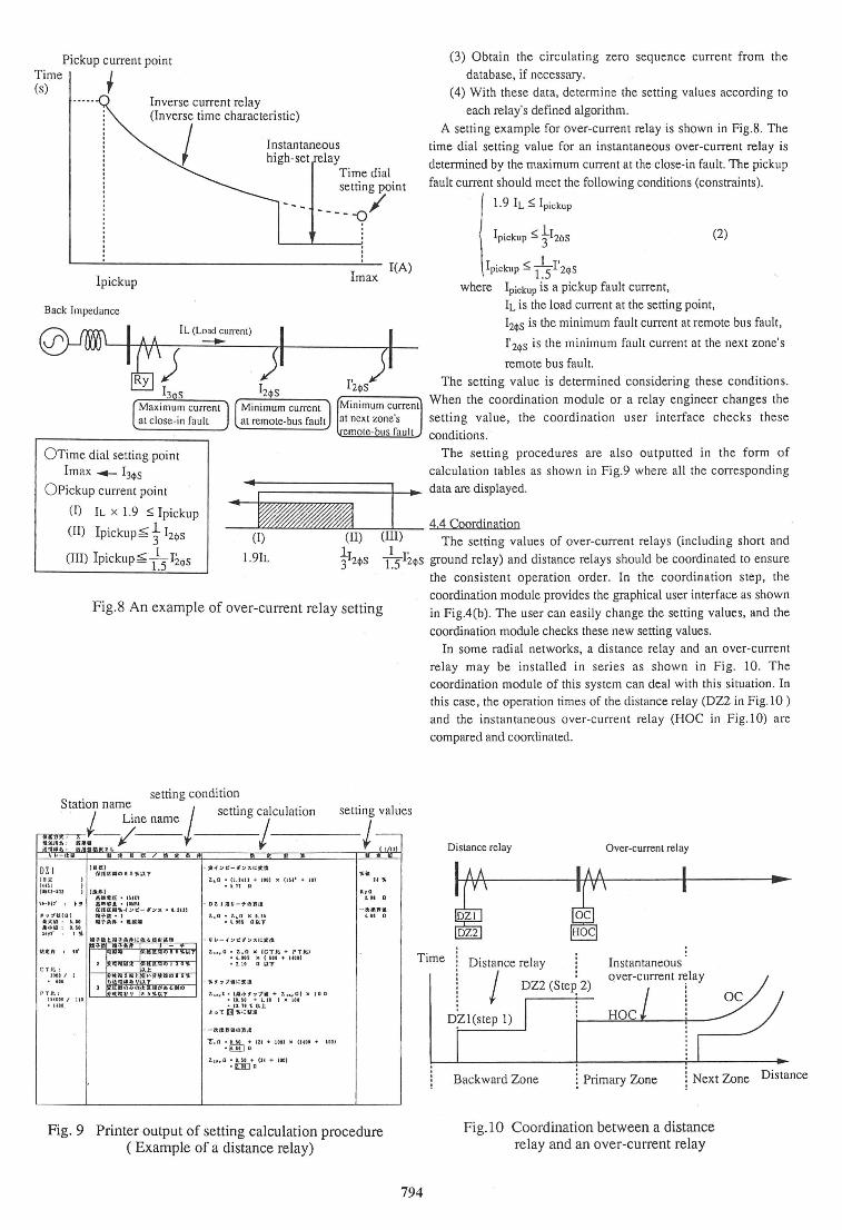
A setting example for over-current relay is shown in Fig.8. The
time dial setting value for an instantaneous over-current relay is
determined by the maximum current at the close-in fault. The pickup
fault current should meet the following conditions (constraints).
l. 9 IL :5: Ipickup
(2)
lpickup :5: l ~S I'2$S
where Ipickup is a pickup fault current,
IL is the load current at the setting point,
I2$5 is the minimum fault current at remote bus fault,
1'2<1> 5 is the minimum fault current at the next zone's
remote bus fault.
The setting value is determined considering these conditions.
When the coordination module or a relay engineer changes the
setting value, the coordination user interface checks these
conditions. ·
The setting procedures are also outputted in the form of
calculation tables as shown in Fig.9 where all the corresponding
0Pickup current point
(I) IL x 1.9 :5: lpickup
(II) lpickup~ t 12<1> 5 I
., data are displayed.
_ .. _ ..... ~"""'~'""'""~~""""""'""'----=!-,,,-- 4.4 Coordination
...
(ll) (III) The setting values of over-current relays (including short and
-¥2<1>s / 5 I2.<1>s ground relay) and distance relays should be coordinated to ensure (III) lpickup~ /5
I2<1>s
(I)
l.91L
Fig.8 An example of over-current relay setting
DZI lell (CUI (UUl-101 IA~I
a••lE ·um tHlf' .. , 151181. • IOMU
ftftllQ'Jl,..(:.>~-t:.n, •I.HU l'H·D• I I ':17°'~ !01
•:A:ll : l.H • •lolA : I.SI lhf I 1'
C T l!;: JDOI/ I
. "' P Tlt. :
U40U I 111 • 1411,
•TA!t- • taAI
z.~o • (I . Un+ !DI) x (JU' + U} • I . ll Q
z.,a . z~n 11 1.u • l. tU QQ'1
l.,.,a • Z.,O x ICTJt + PTJtl • '·'" x (Ill + 1411} • ! .10 0 lit"f
z., 0 ,l• 1•1'• 1'1':111 + l.,-.,.Ol x 100 •(I. It + 1. 11 ) )I IH •1J. 1t'IEU:.
J:-,T [) 'Jl,1..:llE
· -IJ:f:liJfillCl'))t.111
Y,n • 1.u +tu+ 1011 x ouo + •aa) . !JI] 0
z,.,o • D.H + 114 +JOO) . [ft] [I
.,. 1.H D
-~··ill '·" n
Fig. 9 Printer output of setting calculation procedure (Example of a distance relay)
the consistent operation order. In the coordination step, the
coordination module provides the graphical user interface as shown
in Fig.4(b). The user can easily change the setting values, and the
coordination module checks these new setting values.
In some radial networks, a distance relay and an over-current
relay may be installed in series as shown in Fig. 10. The
coordination module of this system can deal with this situation . In
this case, the operation times of the distance relay (DZ2 in Fig.10 )
and the instantaneous over-current relay (HOC in Fig.10) are
compared and coordinated.
Distance relay Over-current relay
~ f .. DZ2
Time °'7'' ~~~ (S~~ 2)
Instantaneous qver-current relay
794
D,Zl(step 1) HOC
Backward Zone l Primary Zone Next Zone Distance
Fig.10 Coordination between a distance relay and an over-current relay
4.6 Relay simulation
The operation simulation of each relay are also available to check
the final setting values . The simplified sequence of each relay is
used to simulate the operation with the results of fault analysis.
CONCLUSION
An integrated support system for setting and coordination of
protective relays was presented. This system has the following features.
(1) This system has a large scale database system that stores all
necessary relay data of the power systems. This database can
store data on over 10000 relays, 10000 buses, etc.
(2) This system is equipped with advanced fault analysis module.
It has a contingency evaluation mechanism on network
configuration and fault states . Beside the normal fault analysis
such as three-phase short fault and one-phase ground fault, the
fault analysis module provides the circulating zero phase
sequence current analysis. This current causes miss-operation of the ground fault relay.
(3) The setting and coordination modules can execute the setting
calculation of various types of relays such as over-current relay, distance relay, current balance relay, direction comparison relay,
and PCM and FM carrier differential relays.
(4) The entire system is built on an engineering workstation, and it
works in cooperation with other power operation support
systems. Its graphical user inte1face is easy to use, and relay
engineers can specify the setting values as desired.
REFERENCES
[1] IEEE Committee Report, "Computer Aided Coordination of
Line Protection Schemes, IEEE Committee Report", IEEE
Trans. on Power Delivery, Vol. PWRD-6, No.2, April 1991,
pp.575-583. [2] R.P. Graziano, V.J. Kruse, and G.L. Rankin, "System
Analysis of Protection System Coordination: A Strategic
Problem for Transmission and Distribution Reliability", IEEE
Trans. on Power Delivery, Vol. PWRD-7, No.2, April I992,
pp .720-726. f3] K. Suzuki, et al "Interactive Computation System of Distance
Relay Setting for A Large Scale EHV Power System" IEEE
Trams. PAS-99, No.I, 1980, pp .I65-173. [4] M.J. Damborg et al., "Computer Aided Transmission
Protection System Design, Part I: Algorithms" IEEE Trans.
PAS-103, January 1984, pp.51-59.
[5) R. Rarnaswami et al., "Computer Aided Transmission
Protection System Design, Part II : Implementation and
Results" IEEE Trans. PAS-103, January 1984, pp.60-65.
(6) D.E. Schultz and S.S . Waters, "Computer-Aided Protective
Device Coordination, A Case Study" IEEE Trans. PAS-103,
No. II, November 1984, pp.3296-3301. [7) Y. Oura et al., "Interactive Computation System for Relay
Setting and Simulation of Relay Operation in A Large Scale
EHV Power systems" IEEE Trans . PAS-104, No.7, July
I985 , pp.I767-1773.
[8) R. Ramaswami et al., "Enhanced Algorithms for
Transmission Protective Relay Coordination" IEEE Trans.on
Power Delivery, Vol. PWRD-I, No. l, Jan . I986, pp.280-
287.
[9] R. Zimmering and R. Allen, "Computerization of A Large
Relay Setting File" IEEE Trans. on Power Delivery , Vol.
PWRD-1, No.l, Jan . 1986, pp.135-142.
[10) S.S. Venkata et al., "C.A.E. Software for Transmission
Protection Systems: Puget Power Experience" IEEE Trans .. on
Power Delivery, Vol. PWRD-2, No.3, July 1987, pp.691-
698. [11) K.A. Brown and J.M. Parker "A personal Computer
Approach to Overcurrent Protective Device Coordination" IEEE
Trans. on Power Delivery, Vol. PWRD-3, No.2, April 1988,
pp.509-513. [12) V.V.B. Rao and K.S. Rao, "Computer-Aided Coordination
of Overcurrent Relays: Determination of Break Points" IEEE
Trans. on Power Delivery, Vol. PWRD-3, No.2, April 1988,
pp.545-548. [13) A.K. Jampala et al "Adaptive Transmission Protection:
Concepts and Computational Issues", IEEE Trans. on Power
Delivery, Vol. PWRD-4, No.I, Jan. 1989, pp.177-185.
[14) R. Ramaswami et al., "Enhanced Algorithms for
Transmission Protective Relay Coordination" IEEE Trans.on Power Delivery, Vol. PWRD-1, No.I, Jan. 1986, pp .280-
287. [15) R. Rarnaswami, M.J. Damborg, S.S . Venkata,
"Coordination of Directional Relays in Transmission System -
A Subsystem Approach", IEEE Trans.on Power Delivery, Vol.
PWRD-5, No.1, Jan. I990, pp.64-71.
795
[16) T. Haba et al, "An Expert System for Switch Operation
Planning in Line Dispatching", Proc. of the third Symposium
on Expert Systems Application to Power Systems, Tokyo
Kobe, April, 1991, pp.300-307.