Embed Size (px)
Citation preview
PIERS ONLINE, VOL. 4, NO. 8, 2008 876
Integrated Robotic Plasma Spraying System for AdvancedMaterials Processing
Weisheng Xia1,2, Haiou Zhang2, Gui-Lan Wang1,Yunzhen Yang1, Guangchao Han3, and Haiping Zou1
1State Key Laboratory of Materials Processing and Die & Mould TechnologyHuazhong University of Science and Technology, Wuhan 430074, China
2State Key Laboratory of Digital Manufacturing and Equipment TechnologyHuazhong University of Science and Technology, Wuhan 430074, China
3China University of Geosiences, China
Abstract— During atmospheric plasma spraying (APS), to control the time dependent D.C.plasma jet behavior requires the comprehensive understanding of its electric, magnetic, thermal,thermodynamic phenomena. In this paper, influence of particles injection with the form ofsuspension on the fluctuation of plasma jet is analyzed, and a control approach is presentedto eliminate the effect. Moreover, an integrated robotic plasma spraying system for advancedmaterials processing, i.e., rapid metal tooling and solid oxide fuel cell (SOFC), is developed,which combines a PC-based controller with a six-axis robot. The intelligent adaptive adjustmentof robot spraying trajectories and self-dispatch of manufacturing strategies were carried out bythe resultant system according to the feedback of the temperature and thickness of sprayedcoatings and other information during plasma praying. The flexibility of the forming systemwas promoted by integrating plasma spray forming with robot motion control. Excellent controlperformance is observed and this system can be effective to meet the requirements of differentmaterials processing techniques.
1. INTRODUCTION
Atmospheric plasma spraying (APS) has already been applied in widespread industries for a varietyof applications due to its low cost and simplicity [1]. It can rapidly manufacture coatings withalmost all kinds of materials, such as metals, alloys, ceramics and polymers. Hence, APS hassuccessfully shifted from a traditional technology for surface engineering to a versatile materialprocessing one, and drawn keen attention especially for its noteworthy application of solid oxidefuel cells (SOFCs) [2, 3].
Meanwhile, there is an increasing use of robot in industry domains because of its high flexibilityand broad operating region [4, 5]. For further study on rapid tooling using plasma thermal spraytechnology, we conducted developmental research of combining the industry robotic technology andplasma thermal spray technology to establish integrated robotic rapid spray metal tooling processfor manufacturing injection molding tools and sheet metal forming dies.
2. INTEGRATED ROBOTIC PLASMA SPRAYING SYSTEM
2.1. System Design and SetupAs a line-of-sight process, APS can fabricate satisfying coatings with complex geometries throughholding spray guns by a robot. It is very easy and simple to generate a spray trajectory or modifyprocessing parameters by using a programmable robot, such as spray angle, spray distance, scanningvelocity and step, etc. Moreover, robotic plasma spraying has proved a feasible and high-efficientsolution to ensure a high accuracy in process and coating repeatability.
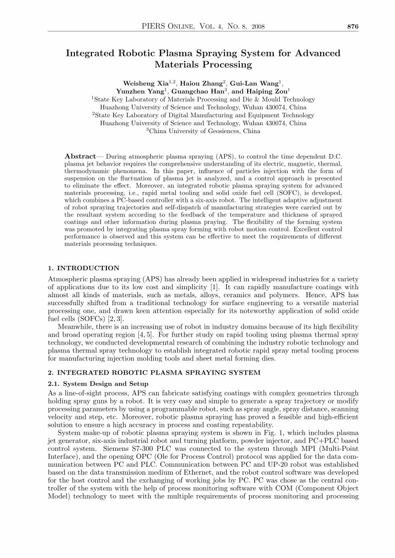
System make-up of robotic plasma spraying system is shown in Fig. 1, which includes plasmajet generator, six-axis industrial robot and turning platform, powder injector, and PC+PLC basedcontrol system. Siemens S7-300 PLC was connected to the system through MPI (Multi-PointInterface), and the opening OPC (Ole for Process Control) protocol was applied for the data com-munication between PC and PLC. Communication between PC and UP-20 robot was establishedbased on the data transmission medium of Ethernet, and the robot control software was developedfor the host control and the exchanging of working jobs by PC. PC was chose as the central con-troller of the system with the help of process monitoring software with COM (Component ObjectModel) technology to meet with the multiple requirements of process monitoring and processing
PIERS ONLINE, VOL. 4, NO. 8, 2008 877
optimization, information storage, computing resources and so on. Hence, the superiorities of PLCover the stable and safe control of field apparatus and that of PC over process monitoring, datastorage, control algorithm were effectively integrated to enhance the system function. Finally, therobotic plasma spray forming system was established accompanied with forming process monitor-ing, intelligent adaptive adjustment of robot spraying trajectories, real-time control of robot andother functions. The intelligent adaptive adjustment of robot spraying trajectories and self-dispatchof manufacturing strategies were carried out by the resultant system according to the feedback ofthe temperature and thickness of sprayed coatings during plasma praying [6].
Figure 1: Schematic diagram of robotic plasma spray forming system.
2.2. Influence of Suspension Injection on the Fluctuation of Plasma Jet
During plasma spraying, to control the time dependent D.C. plasma jet behavior requires thecomprehensive understanding of its electric, magnetic, thermal, thermodynamic phenomena. Thearc fluctuations already have an important influence on particles velocities and temperatures. Thisinfluence is by far more important with the suspension injection because fluctuations act on dropsor jet penetration, fragmentation, particle trajectories, heating and acceleration. Plasma properties(e.g., velocity, specific enthalpy, gas mass density) vary continuously along the plasma jet radiusi.e., along the suspension penetration path toward the plasma jet axis [7]. The instabilities of thearc root of the D.C. torch involve high transient voltage fluctuations and thus dissipated powerfluctuations, resulting in plasma jets varying continuously in length and position [8] with strongvariations of their velocities in the axial direction.
(a) (b)
Figure 2: Experimental set-up of (a) SPS and (b) the atomization profile of suspension.
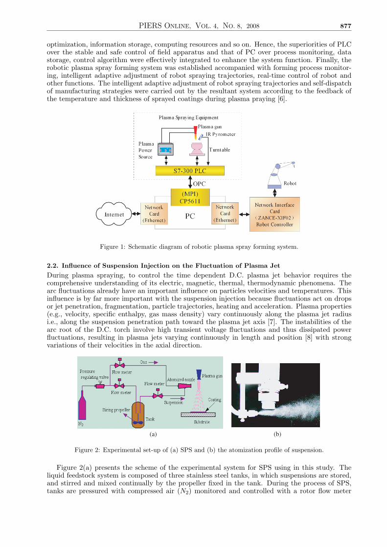
Figure 2(a) presents the scheme of the experimental system for SPS using in this study. Theliquid feedstock system is composed of three stainless steel tanks, in which suspensions are stored,and stirred and mixed continually by the propeller fixed in the tank. During the process of SPS,tanks are pressured with compressed air (N2) monitored and controlled with a rotor flow meter
PIERS ONLINE, VOL. 4, NO. 8, 2008 878
and pressure regulating valve. It is worth noting first that the momentum of the liquid dropletshas to be high enough to ensure their penetration into the core of the plasma jet. Hence, theatomized nozzle was self-designed with three inlets for suspensions and one inlet for the atomizinggas. Picture of suspension drops by the atomized nozzle is shown in Fig. 2(b). Hence, the liquidfeedstock system can be used for the SPS process of three different suspension compositions, andthe pressure of the tank of the suspension feeders can be varied to modify the drop velocities.
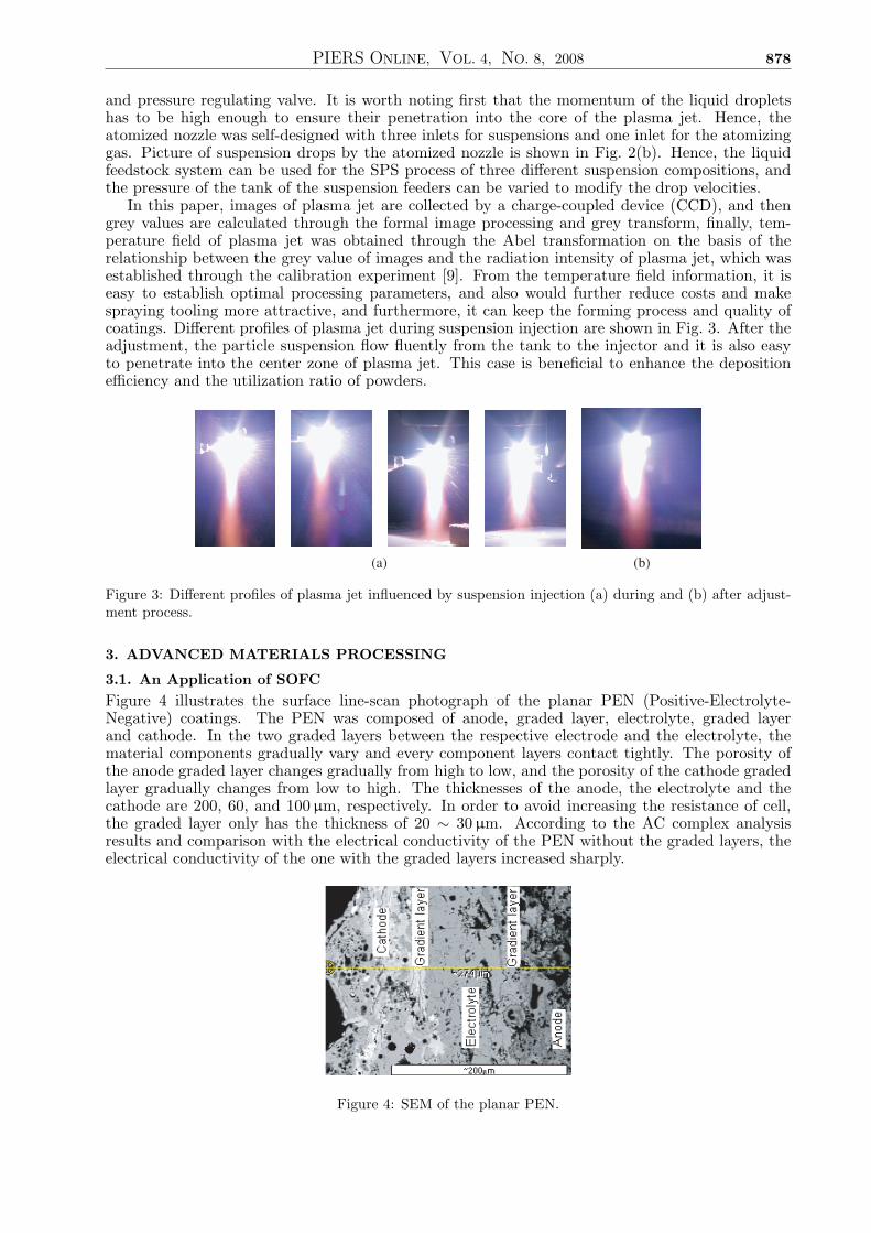
In this paper, images of plasma jet are collected by a charge-coupled device (CCD), and thengrey values are calculated through the formal image processing and grey transform, finally, tem-perature field of plasma jet was obtained through the Abel transformation on the basis of therelationship between the grey value of images and the radiation intensity of plasma jet, which wasestablished through the calibration experiment [9]. From the temperature field information, it iseasy to establish optimal processing parameters, and also would further reduce costs and makespraying tooling more attractive, and furthermore, it can keep the forming process and quality ofcoatings. Different profiles of plasma jet during suspension injection are shown in Fig. 3. After theadjustment, the particle suspension flow fluently from the tank to the injector and it is also easyto penetrate into the center zone of plasma jet. This case is beneficial to enhance the depositionefficiency and the utilization ratio of powders.
(a) (b)
Figure 3: Different profiles of plasma jet influenced by suspension injection (a) during and (b) after adjust-ment process.
3. ADVANCED MATERIALS PROCESSING
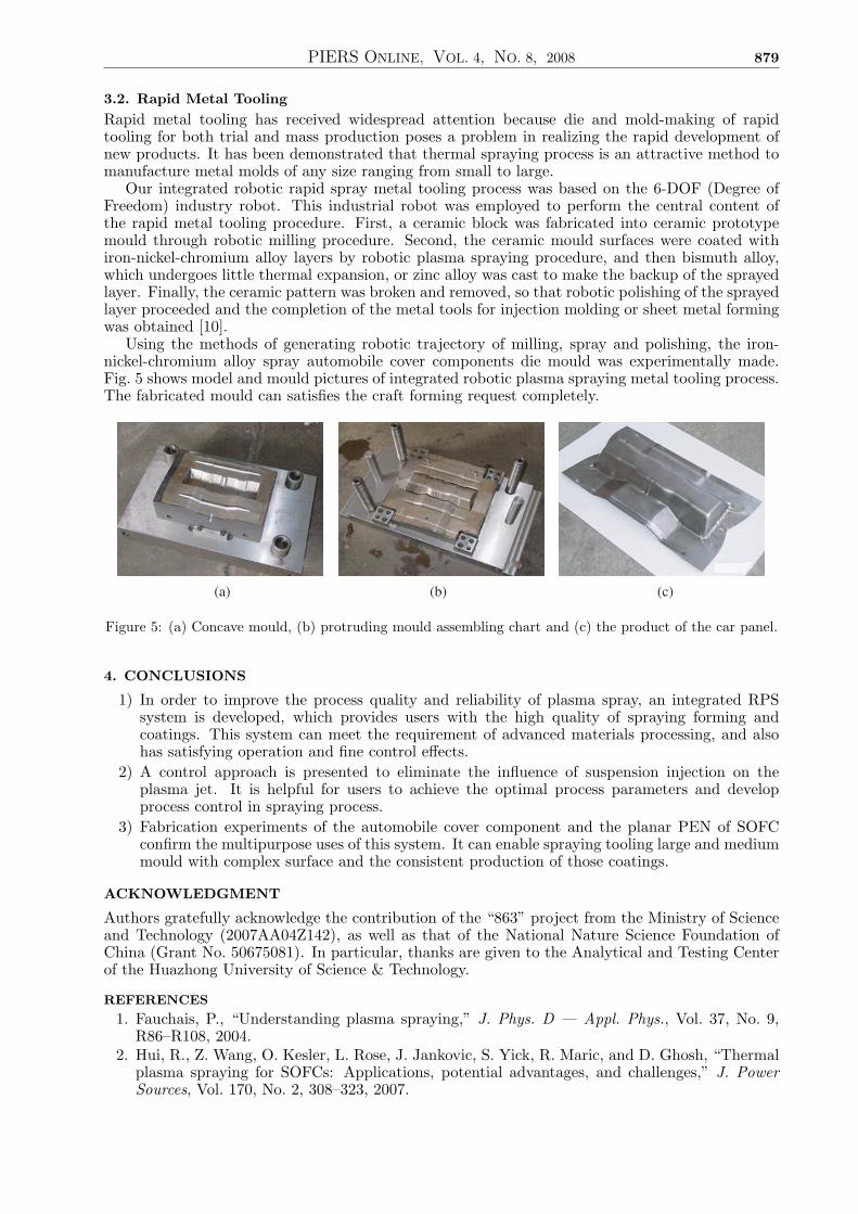
3.1. An Application of SOFCFigure 4 illustrates the surface line-scan photograph of the planar PEN (Positive-Electrolyte-Negative) coatings. The PEN was composed of anode, graded layer, electrolyte, graded layerand cathode. In the two graded layers between the respective electrode and the electrolyte, thematerial components gradually vary and every component layers contact tightly. The porosity ofthe anode graded layer changes gradually from high to low, and the porosity of the cathode gradedlayer gradually changes from low to high. The thicknesses of the anode, the electrolyte and thecathode are 200, 60, and 100µm, respectively. In order to avoid increasing the resistance of cell,the graded layer only has the thickness of 20 ∼ 30µm. According to the AC complex analysisresults and comparison with the electrical conductivity of the PEN without the graded layers, theelectrical conductivity of the one with the graded layers increased sharply.
Figure 4: SEM of the planar PEN.
PIERS ONLINE, VOL. 4, NO. 8, 2008 879
3.2. Rapid Metal ToolingRapid metal tooling has received widespread attention because die and mold-making of rapidtooling for both trial and mass production poses a problem in realizing the rapid development ofnew products. It has been demonstrated that thermal spraying process is an attractive method tomanufacture metal molds of any size ranging from small to large.
Our integrated robotic rapid spray metal tooling process was based on the 6-DOF (Degree ofFreedom) industry robot. This industrial robot was employed to perform the central content ofthe rapid metal tooling procedure. First, a ceramic block was fabricated into ceramic prototypemould through robotic milling procedure. Second, the ceramic mould surfaces were coated withiron-nickel-chromium alloy layers by robotic plasma spraying procedure, and then bismuth alloy,which undergoes little thermal expansion, or zinc alloy was cast to make the backup of the sprayedlayer. Finally, the ceramic pattern was broken and removed, so that robotic polishing of the sprayedlayer proceeded and the completion of the metal tools for injection molding or sheet metal formingwas obtained [10].
Using the methods of generating robotic trajectory of milling, spray and polishing, the iron-nickel-chromium alloy spray automobile cover components die mould was experimentally made.Fig. 5 shows model and mould pictures of integrated robotic plasma spraying metal tooling process.The fabricated mould can satisfies the craft forming request completely.
(a) (b) (c)
Figure 5: (a) Concave mould, (b) protruding mould assembling chart and (c) the product of the car panel.
4. CONCLUSIONS
1) In order to improve the process quality and reliability of plasma spray, an integrated RPSsystem is developed, which provides users with the high quality of spraying forming andcoatings. This system can meet the requirement of advanced materials processing, and alsohas satisfying operation and fine control effects.
2) A control approach is presented to eliminate the influence of suspension injection on theplasma jet. It is helpful for users to achieve the optimal process parameters and developprocess control in spraying process.
3) Fabrication experiments of the automobile cover component and the planar PEN of SOFCconfirm the multipurpose uses of this system. It can enable spraying tooling large and mediummould with complex surface and the consistent production of those coatings.
ACKNOWLEDGMENT
Authors gratefully acknowledge the contribution of the “863” project from the Ministry of Scienceand Technology (2007AA04Z142), as well as that of the National Nature Science Foundation ofChina (Grant No. 50675081). In particular, thanks are given to the Analytical and Testing Centerof the Huazhong University of Science & Technology.
REFERENCES
1. Fauchais, P., “Understanding plasma spraying,” J. Phys. D — Appl. Phys., Vol. 37, No. 9,R86–R108, 2004.
2. Hui, R., Z. Wang, O. Kesler, L. Rose, J. Jankovic, S. Yick, R. Maric, and D. Ghosh, “Thermalplasma spraying for SOFCs: Applications, potential advantages, and challenges,” J. PowerSources, Vol. 170, No. 2, 308–323, 2007.
PIERS ONLINE, VOL. 4, NO. 8, 2008 880
3. Henne, R., “Solid oxide fuel cells: A challenge for plasma deposition processes,” J. ThermSpray Technol., Vol. 16, No. 3, 381–403, 2007.
4. Nassenstein, K. and D. Luckenbach, “Progress in thermal spray processes,” Thermal SprayConnects: Explore Its Surfacing Potential!, 378–382, Basel, Switzerland, 2005.
5. Vergeest, J. S. M. and J. W. H. Tangelder, “Robot machines rapid prototype,” Ind. Robot,Vol. 23, No. 5, 17–20, 1996.
6. Xia, W.-S., H.-O. Zhang, G.-L. Wang, Y.-Z. Yang, and Y. Zou, “Open architecture roboticplasma spray forming system based on Ethernet,” Robot, Vol. 30, No. 1, 17–21, 2008 (inChinese).
7. Etchart-Salas, R., V. Rat, J. Coudert, P. Fauchais, N. Caron, K. Wittman, and S. Alexandre,“Influence of plasma instabilities in ceramic suspension plasma spraying,” J. Therm SprayTechnol., Vol. 16, No. 5, 857–865, 2007.
8. Coudert, J. F., M. P. Planche, and P. Fauchais, “Characterization of D.C. plasma torch voltagefluctuations,” Plasma Chem. Plasma Process., Vol. 16, No. 1, S211–S227, 1995.
9. Xia, W., H. Zhang, G. Wang, and D. Liu, “Plasma jet temperature field diagnostics for processcontrol in rapid plasma spray tooling,” ICMA 2004 — International Conference on Manu-facturing Automation: Advanced Design and Manufacturing in Global Competition, 771–776,Wuhan, China, 2004.
10. Zhang, H., G. Wang, Y. Luo, and T. Nakaga, “Rapid hard tooling by plasma spraying forinjection molding and sheet metal forming,” Thin Solid Films, Vol. 390, No. 1–2, 7–12, 2001.