Embed Size (px)
Citation preview

Integrated Modeling and Optimization ofLunar In-Situ Resource Utilization Systems
Samuel S. SchreinerMassachusetts Institute
of TechnologyCambridge, MA 02139
Jeffrey A. HoffmanMassachusetts Institute
of TechnologyCambridge, MA 02139
Gerald B. SandersJohnson Space Center
Houston, TX 77058
Kristopher A. LeeJohnson Space Center
Houston, TX 77058
Abstract—The production of oxygen from lunar regolith, a formof In-Situ Resource Utilization (ISRU), is a mission-enablingtechnology that can break the supply logistics chain from Earthto support sustained, affordable space exploration. We presentthe development of an integrated ISRU system model to studyand optimize the system mass and power requirements, acritical development in understanding the proper applicationof ISRU systems. The integrated model includes subsystemmodels for a Molten Regolith Electrolysis (MRE) reactor, anexcavator, a hopper and feed system, the power system, andan oxygen liquefaction and storage system. A hybrid genetic-algorithm/gradient-based optimization scheme is implementedto optimize the ISRU system design across a range of productionlevels. Lower oxygen production levels (<1500 kg/yr) are bestmanaged with a single reactor operating at a traditional tem-perature of 1900K and a batch time of 2-3 hrs. Larger oxygenproduction levels are best met with multiple reactors that eachproduce ∼2500 kg/yr, operate at 2200K, and have a batch timearound 1 hr. It is found that an MRE reactor can generate theentire ISRU system’s mass worth of oxygen in as little as 52 daysat a rate of 7 kg of oxygen annually per kilogram system mass.
TABLE OF CONTENTS
1 INTRODUCTION . . . . . . . . . . . . . . . . . . . . . . . . . . . . . . . . . . 12 SYSTEM MODEL DESCRIPTION . . . . . . . . . . . . . . . . . 23 ISRU SYSTEM INTEGRATION . . . . . . . . . . . . . . . . . . . 54 OPTIMIZATION TECHNIQUE . . . . . . . . . . . . . . . . . . . . 65 ISRU SYSTEM OPTIMIZATION . . . . . . . . . . . . . . . . . . 66 CONCLUSIONS . . . . . . . . . . . . . . . . . . . . . . . . . . . . . . . . . . . 9
ACKNOWLEDGMENTS . . . . . . . . . . . . . . . . . . . . . . . . . . . 10BIOGRAPHY . . . . . . . . . . . . . . . . . . . . . . . . . . . . . . . . . . . . . 11
1. INTRODUCTIONOne of the most significant barriers to space exploration is theburden of bringing all of the material resources from Earthrequired for a mission. To enable sustainable, affordablespace exploration, the reliance on Earth’s resources must bereduced. In-situ resource utilization (ISRU), or leveragingextraterrestrial resources to support space missions, can sig-nificantly reduce the required launch mass and cost for agiven mission [1, 2].
One avenue for utilizing space resources is producing oxy-gen on the lunar surface. The production of oxygen fromlunar regolith is a architecture-enabling technology that cansignificantly reduce the supply logistics chain from Earth.Oxygen is a major component of launch vehicle, spacecraft,and lander masses (∼70% of launch vehicle mass) and atthe same time is one of the most abundant lunar resources
978-1-4799-5380-6/15/$31.00 c©2015 IEEE.
(lunar soil is ∼44% oxygen by weight) [3]. The productionof this valuable resource outside of Earth’s gravity well cansupport lunar surface activities or enable orbital refueling todrastically reduce mission cost. The 1993 “LUNOX” studyby Johnson Space Center investigated the possible benefits ofproducing oxygen on the Moon for early lunar explorationmissions and found an associated reduction in launch vehiclemass and a 50% reduction program cost.
Sherwood and Woodcock [2] conducted an economic anal-ysis of producing oxygen on the lunar surface to supplylander ascent propellant. They determined that lunar ISRUhas great potential to be economically feasible, but “thesensitivities [of their economic model] are modest, except forthe mass of production hardware” [2]. Thus, it is imperativeto accurately model the mass and performance of ISRU sys-tems to determine economic feasibility. Furthermore, ISRUsystem models can provide guidance for both the hardwaredevelopment and mission applications of such systems [4].
The oxygen in lunar soil is primarily bound up in oxides andthere are over twenty different oxygen extraction methodsproposed in the literature [1, 5, 6]. In the past decade,three of these methods have undergone dramatic technologymaturation: Hydrogen Reduction of Ilmenite (HRI), Carboth-ermal Reduction of Silicates (CRS), and Molten RegolithElectrolysis (MRE) [7]. Previous research has extensivelymodeled HRI and CRS reactors [4, 8, 9, 10, 11] but asuitably mature model for an MRE reactor has only recentlybeen developed [12]. MRE is an electrochemical processingtechnique that performs direct electrolysis on molten lunarregolith to produce gaseous oxygen at the anode and liquidmetals at the cathode.
There is a strong impetus to explore the feasibility of an ISRUsystem with an MRE reactor, as there are many potentialbenefits to such a system. Utilizing MRE may result inconsiderable mass savings compared to the other two primarytechniques (HRI and CRS), as it can theoretically extractall of the oxygen from lunar regolith [13]. MRE does notrequire either a gas recycling system or a water electrolyzer,which may also reduce system mass. Other benefits includethe synergistic production of materials such as iron, silicon,aluminum and glassy materials. These byproducts of oxygenproduction can be used to construct spare parts, buildings andsolar arrays on the lunar surface [14]. Conversely, MRE mayrequire more power due to the high operating temperaturecompared to HRI or CRS. Additionally, MRE is at a lowertechnology readiness level (TRL) and thus requires moretechnology development.
In light of the recent evidence in support of water in the polarlunar craters [15], there remain many potential benefits tousing MRE on the lunar surface, perhaps even in parallelwith a water extraction scheme. First, there is significant
1

uncertainty as to the state and concentration of the waterin lunar craters [15]. A resource prospecting mission isnecessary to ascertain ground truth and is currently plannedto launch in 2019 [16]. MRE may be concurrently devel-oped using composition data from the Apollo lunar samples.Technical challenges associated with feedstock excavationon the poles, especially excavation from within permanentlyshadowed craters, can also be avoided with the MRE process.
This work integrates an MRE reactor model [12] into anISRU system model. Previous work in integrated ISRUsystem modeling provided a foundation for this analysis, butdid not include a power system, and suitable models for anMRE reactor and excavation system were not available atthe time [9, 17]. The system model presented in this workexpands upon previous work to encapsulate a more completesystem by including subsystem models of the reactor, powersystem, excavation system, oxygen storage and liquefactionsystem, as well as a hopper and regolith feed system. Byevaluating the integrated ISRU system, the holistic systemperformance may be studied and optimized, rather than justthe reactor subsystem. A hybrid genetic algorithm/gradient-based optimization routine is developed, validated, and ex-ercised to minimize the ISRU system mass over a range ofoxygen production levels.
Section 2 provides an overview of the subsystem models.In Section 3, the integrated system model is presented andthe details of the subsystem connections are presented withan N2 diagram. Section 4 provides an overview of theoptimization technique implemented on the ISRU systemmodel. In Section 5, the optimized system design over a rangeof oxygen production levels is explored. Section 6 concludeswith some key aspects of the optimized system and providesrecommendations for future work.
2. SYSTEM MODEL DESCRIPTIONReactor
Although a variety of reactor models can be integrated intothe system model, this work utilized a Molten RegolithElectrolysis (MRE) reactor model [12] to better understandthe system-level implications of that processing technique.As shown in Figure 1, the reactor modeled includes an outercylindrical shell with three layers: an outer structural layer,a middle insulation layer, and an inner refractory layer formanaging the corrosive molten metals produced. The anodeand cathode, composed of a shaft and plate, extend into themolten region from the top and bottom, respectively. The redlines depict current streamlines through the inner molten coreof the reactor.
The reactor model uses electrochemistry to estimate the cur-rent and voltage. The current is directly related to the oxygenproduction rate:
I = (nO2)nF
η, (1)
where nO2 is the desired molar oxygen production rate(mol/s), n is the number of electrons required per diatomicoxygen (4), F is Faraday’s constant, and η is the averagecurrent efficiency over an entire batch. The instantaneouscurrent efficiency depends upon which oxide is currentlybeing electrolyzed and can range from 30-60% for ironoxides and is near 100% for melts once the iron oxide hasbeen depleted [18]. This means that the average efficiencydepends upon the composition of regolith and will therefore
Phase-Boundaryw1500KI
Molten-Regolith-Corewcurrent-streamlines-in-redI
CathodewFe2+I+2e--→-FewlI
wSi4+I+4e--→-SiwlI
Temp-wKI
AnodewO2-I-→-2e--+-1/2O2wgI
PowerSource-
--
Structure
InsulationRefractory
Figure 1. The anatomy of a Molten Regolith Electrolysis(MRE) reactor. Also shown are the temperature and current
profiles from a multiphysics simulation that was used topredict reactor performance and tune reactor design.
be dependent upon lunar location. For example, the higheriron concentration in the mare regions will result in a loweraverage current efficiency [12].
The reactor model translates the oxygen production rate intothe required regolith processing rate using the fraction ofoxygen that can be extracted from regolith. Due to the factthat an MRE reactor can extract oxygen from all oxide speciesin lunar regolith, the contribution from each oxide speciemust be summed together:
moxygen
mregolith=
∑i
(wi)MWO2
MWoxide,i(rmol,i)(efrac,i) (2)
where wi is the weight percent of oxide i in lunar regolith,MW is the molar weight (of oxygen or an oxide), rmol,i isthe number of moles of oxygen per mole of oxide i ( molO2
moloxide),
and efrac,i is the fraction of oxide i that is electrolyzed ineach batch. The fraction of each oxide specie that can be elec-trolyzed is strongly dependent upon operating temperature,because the solidification temperature of the melt generallyincreases throughout electrolysis. In the MRE reactor model,the electrolysis process is allowed to progress until the meltsolidification temperature is within 50 K of the operating tem-perature to allow for a safety margin. Thus, higher operatingtemperatures allow the reactor to extract more oxygen perkilogram regolith, but also results in a higher heat loss to theenvironment. This is one tradeoff that is optimized using thesystem model.
One key factor in the design of an MRE reactor is thecontainment of molten regolith. Molten lunar regolith isextremely corrosive and cannot be contained for extendedperiods of time by traditional crucible materials [13]. A joule-heated, cold-wall reactor, similar to the Hall-Heroult cellsin the aluminum production industry, is an elegant solutionto the challenge of molten regolith containment. In thisconcept, the reactor maintains a molten regolith core via theheat generated by the current passing through the resistivemelt, while the molten region is surrounded by solid regoliththat insulates and protects the side walls of the reactor fromcorrosion [19].
2
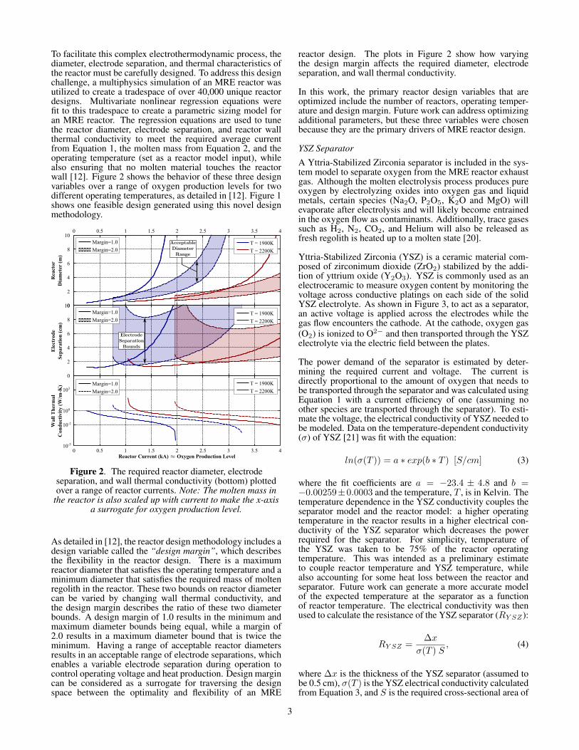
To facilitate this complex electrothermodynamic process, thediameter, electrode separation, and thermal characteristics ofthe reactor must be carefully designed. To address this designchallenge, a multiphysics simulation of an MRE reactor wasutilized to create a tradespace of over 40,000 unique reactordesigns. Multivariate nonlinear regression equations werefit to this tradespace to create a parametric sizing model foran MRE reactor. The regression equations are used to tunethe reactor diameter, electrode separation, and reactor wallthermal conductivity to meet the required average currentfrom Equation 1, the molten mass from Equation 2, and theoperating temperature (set as a reactor model input), whilealso ensuring that no molten material touches the reactorwall [12]. Figure 2 shows the behavior of these three designvariables over a range of oxygen production levels for twodifferent operating temperatures, as detailed in [12]. Figure 1shows one feasible design generated using this novel designmethodology.
Rea
ctor
Dia
met
erT(
m)
0 0.5 1 1.5 2 2.5 3 3.5 4
0
2
4
6
8
10
Ele
ctro
de
Sep
arat
ion
T(cm
)
0
2
4
6
8
10
ReactorTCurrentT(kA) OxygenTProductionTLevel
Wal
lTTh
erm
alC
ond
uct
ivit
yT(W
/m-K
)
0 0.5 1 1.5 2 2.5 3 3.5 410-5
10-2
100
103
T = 1900K
T = 2200K
T = 1900K
T = 2200K
T = 1900K
T = 2200K
~~
ElectrodeSeparationBounds
AcceptableDiameterRange
Margin=1.0
Margin=2.0
Margin=1.0
Margin=2.0
Margin=1.0
Margin=2.0
Figure 2. The required reactor diameter, electrodeseparation, and wall thermal conductivity (bottom) plottedover a range of reactor currents. Note: The molten mass in
the reactor is also scaled up with current to make the x-axisa surrogate for oxygen production level.
As detailed in [12], the reactor design methodology includes adesign variable called the “design margin”, which describesthe flexibility in the reactor design. There is a maximumreactor diameter that satisfies the operating temperature and aminimum diameter that satisfies the required mass of moltenregolith in the reactor. These two bounds on reactor diametercan be varied by changing wall thermal conductivity, andthe design margin describes the ratio of these two diameterbounds. A design margin of 1.0 results in the minimum andmaximum diameter bounds being equal, while a margin of2.0 results in a maximum diameter bound that is twice theminimum. Having a range of acceptable reactor diametersresults in an acceptable range of electrode separations, whichenables a variable electrode separation during operation tocontrol operating voltage and heat production. Design margincan be considered as a surrogate for traversing the designspace between the optimality and flexibility of an MRE
reactor design. The plots in Figure 2 show how varyingthe design margin affects the required diameter, electrodeseparation, and wall thermal conductivity.
In this work, the primary reactor design variables that areoptimized include the number of reactors, operating temper-ature and design margin. Future work can address optimizingadditional parameters, but these three variables were chosenbecause they are the primary drivers of MRE reactor design.
YSZ Separator
A Yttria-Stabilized Zirconia separator is included in the sys-tem model to separate oxygen from the MRE reactor exhaustgas. Although the molten electrolysis process produces pureoxygen by electrolyzing oxides into oxygen gas and liquidmetals, certain species (Na2O, P2O5, K2O and MgO) willevaporate after electrolysis and will likely become entrainedin the oxygen flow as contaminants. Additionally, trace gasessuch as H2, N2, CO2, and Helium will also be released asfresh regolith is heated up to a molten state [20].
Yttria-Stabilized Zirconia (YSZ) is a ceramic material com-posed of zirconimum dioxide (ZrO2) stabilized by the addi-tion of yttrium oxide (Y2O3). YSZ is commonly used as anelectroceramic to measure oxygen content by monitoring thevoltage across conductive platings on each side of the solidYSZ electrolyte. As shown in Figure 3, to act as a separator,an active voltage is applied across the electrodes while thegas flow encounters the cathode. At the cathode, oxygen gas(O2) is ionized to O2− and then transported through the YSZelectrolyte via the electric field between the plates.
The power demand of the separator is estimated by deter-mining the required current and voltage. The current isdirectly proportional to the amount of oxygen that needs tobe transported through the separator and was calculated usingEquation 1 with a current efficiency of one (assuming noother species are transported through the separator). To esti-mate the voltage, the electrical conductivity of YSZ needed tobe modeled. Data on the temperature-dependent conductivity(σ) of YSZ [21] was fit with the equation:
ln(σ(T )) = a ∗ exp(b ∗ T ) [S/cm] (3)
where the fit coefficients are a = −23.4 ± 4.8 and b =−0.00259±0.0003 and the temperature, T , is in Kelvin. Thetemperature dependence in the YSZ conductivity couples theseparator model and the reactor model: a higher operatingtemperature in the reactor results in a higher electrical con-ductivity of the YSZ separator which decreases the powerrequired for the separator. For simplicity, temperature ofthe YSZ was taken to be 75% of the reactor operatingtemperature. This was intended as a preliminary estimateto couple reactor temperature and YSZ temperature, whilealso accounting for some heat loss between the reactor andseparator. Future work can generate a more accurate modelof the expected temperature at the separator as a functionof reactor temperature. The electrical conductivity was thenused to calculate the resistance of the YSZ separator (RY SZ):
RY SZ =∆x
σ(T ) S, (4)
where ∆x is the thickness of the YSZ separator (assumed tobe 0.5 cm), σ(T ) is the YSZ electrical conductivity calculatedfrom Equation 3, and S is the required cross-sectional area of
3

GaseousO2,gNa,gK,gP,getc.g
fromgReactor
O2-
O2gGas
YSZgFilter
CathodegPlating
AnodegPlating
DrivingPowergSource
Figure 3. A diagram of the proposed YSZ schematic for usewith the Molten Regolith Electrolysis reactor.
the YSZ separator calculated as:
S =IY SZ
j, (5)
where IY SZ is the required current through the YSZ sep-arator and j, the limiting current density, was taken to be0.4 A/cm2 [22]. The power of the YSZ ceramic was estimatedusing the current and resistance (I2R). The dimensions ofthe separator and a 304 Stainless Steel casing are used tocalculate the YSZ separator mass.
It should be noted that the YSZ separator model is a sim-plified version with the intention of determining the powerneeded for oxygen separation with only first-order estimatesof mass and volume. It is believed that the power requirementof the YSZ separator will play a much more significant rolethan its mass in the ISRU system optimization. YSZ oxy-gen separators are commonly composed of multiple packedtubes or stacked wafers, which could reduce the mass andvolume estimates, but not significantly change the powerrequirement, compared to this simplified YSZ model. A morerealistic mass model will be created in a future iteration.
Excavator
The excavator system, developed at the Glenn Research Cen-ter [23], predicts the mass of a mobile excavation platformsized to deliver the regolith throughput requirement to thereactor. A force module utilizes the Balovnev force equationsto generate estimates of the force and torque involved in exca-vating lunar regolith. A hole depth of 25 cm with cut depthsof 2.5 cm was used to size a front-end loader in this systemmodel. The excavation force estimates are used to size theexcavation actuators using commercial off-the-shelf (COTS)actuators and controllers from Danaher2. The force modulealso determines the vehicle reaction and traction forces. Amass module conducts a structural analysis to ensure that theexcavator chassis can support the regolith weight and thatthe digging mechanism can support the expected excavationstresses. The locomotion motors are modeled after the Maxonmotors used on the Mars Exploration Rover [24].
2http://www.danahermotion.com
An excavator speed of 0.5 m/s and a plant distance of 100 mare used to properly size themobility platform for the ex-cavator. Information on the excavator operating duty cyclebased on the power system charge/recharge cycle is alsoincorporated into the model. The excavator model utilizesall of this information to generate an excavator design thatcan meet the regolith delivery requirements from the reactorwhile withstanding the excavation forces and regolith loadrequirements.
Hopper and Feed System
The main driver in the hopper model is the buffer capacity, orthe amount of regolith the hopper had to hold in terms of daysof reactor operation. A buffer capacity of 2 days was chosento ensure that the hopper could hold enough regolith forcontinual reactor operation if the excavator needed repairs.Furthermore, a buffer capacity of 2 days effectively decouplesthe excavation system scheduling from reactor batch modeoperation (i.e. although the reactor may operate on a 1 hourbatch time, the excavator can deliver regolith with a lowerfrequency).
The feed system model calculates the mass and power of thesystem required to insert fresh regolith from the hopper intothe reactor. An auger was chosen for this design iteration,but other methods, such as a pneumatic feed system, can bemodeled in the future. The feed system model sizes an augerthat extends from the reactor through a cylindrical sleeve andinto the hopper. Using estimates of the cohesion, internaland external friction angles, and soil-tool adhesion values forlunar regolith, the feed system model estimates the expectedtorque on the auger and the resultant power consumption. Thenumber of feed systems is set equal to the number of reactors,as each reactor will likely require its own feed system. Thesleeve and auger are made out of Hastelloy C-276, due to theinterface with the high-temperature reactor.
One assumption built into the feed system model is that a5 cm diameter auger rotating at 5 rpm would be adequate toinsert a full batch of regolith in the feed time set as an inputin the reactor model. That is, for larger amounts of regolithper batch, the feed system was not parametrically sized up,due to limitations in the model design. Future work canexpand the feed system model to dynamically size the radiusand rotational rate of the auger system to meet the requiredregolith mass flowrate.
Oxygen Liquefaction and Storage
The oxygen liquefaction and storage system utilizes oxygenproduction data from the reactor to size both the liquefactionand storage systems. The liquefaction system determinesthe mass and power of the system required to liquefy theoxygen coming from the reactor, as well as the cooling powerrequired to re-liquefy oxygen that has boiled off in the storagesystem.
For the storage system, a capacity of 6 months was chosento allow for sufficient propellant production to support tworefueling missions per year. The number of layers of MLI canbe chosen to balance heat loss with system mass. Based offof a user material selection, the storage system is sized suchthat the yield stress is less than the hoop stress with a factorof safety of 2. The tank size and number of layers of MLIdirectly impact the boiloff rate due to expected heat leakageinto the tank.
4

Power System
The power subsystem is parametrically sized from the totalpower requirement summed over all of the other subsystems,as shown in Figure 4. A number of options are available inthe power model, including solar arrays without energy stor-age (day-only operation), solar arrays with fuel-cell energystorage to enable lunar night operation, a Stirling radioisotopegenerator, and a fission surface power system. To reduce thedesign tradespace, this study restricted the power system tobe solar cells that provide power to the ISRU system for day-only operation. From a prior NASA study, using this typeof power system in the Shackleton crater rim area resultedin an approximate duty cycle of at least 0.7 (>70% of theyear with continuous uninterrupted solar power), due to thelonger day duration near the lunar poles. Other locationshave a corresponding duty cycle of 0.5. The specific massof the solar array power system without energy storage wastaken to be 20 kg/kWe [25]. Future work can evaluate theeffectiveness of other power systems in the context of a lunarISRU system.
3. ISRU SYSTEM INTEGRATIONThe subsystem models described in the preceding section areintegrated together into a holistic system model. By linkingthe subsystems (reactor, excavator, power, etc.) together intoa self-consistent model, the entire mass and power of an ISRUsystem can be estimated. The self-consistency of the modelallows the tradeoffs between subsystem designs to be studied.For instance, shortening the batch time of an MRE reactor
is one avenue for reducing reactor mass. But this reductionin reactor mass comes at the cost of an increase in reactorpower due to the increase in total down time between batcheswhich reduces total operational time. The integrated modelenables a more complete study of the optimal batch time, asone example, by including the mass of both the power andreactor subsystems.
Another important design variable to optimize is the reactoroperating temperature. Higher operating temperatures in-tuitively result in more radiative heat loss and increase theheating power per kilogram regolith. Conversely, highertemperatures decrease the regolith throughput requirementby increasing the amount of oxygen extracted per kilogramregolith. From an electrochemical point of view, highertemperatures result in a more endothermic reaction. Theintegrated ISRU system model provides a framework to studythe optimal operating temperature.
Figure 4 depicts an N2 diagram of the ISRU system. The pri-mary subsystem couplings are shown, with some secondaryconnections left out for clarity. It is evident that the reactor,described in detail in [12], is a strong driver of many othersystem designs, as one would expect. It is a large driver ofthe power requirement and also sets the regolith processingrequirement which directly affects the excavator, hopper andfeed systems. The power requirement from each subsystemis summed together and used to size the power system. Afterthe power system is sized, the mass of all of the subsystems,including the power system, are summed together to generatean estimate of the total ISRU system mass.
Excavator
Hopper/FeedgSys.
Reactorbs=g
PowergSystem
O2gLiq.gzgStorageg
•lOperatinglTemperature•lBatchlTime•lOperatinglMargin•lflReactors
OxygenlProductionlRateLunarlLocationPowerlSource/availability
RegolithlRequirement
RegolithlRequirement
flofReactors
OxygenProductionRateOxygenlGasTemperature
PowerlReq.
Massl&Volume
TotalgSystemMassgzVolume
OptimiziationVariables = { Constant
MissiongInputs
={
TotalgSystemPower
Figure 4. An N2 diagram of the ISRU system model within the optimization routine, showing how the subsystems areinterconnected to generate a self-consistent estimate of system mass, which is then optimized.
5

4. OPTIMIZATION TECHNIQUEA genetic algorithm (GA) optimization routine was usedwith the holistic system model to optimize the ISRU systemdesign by varying subsystem design variables. A geneticalgorithm method was implemented, rather than traditionalgradient-based optimization techniques, due to the mixed-integer nature of the system: although some parameters werecontinuous, such as operating temperature, the majority ofparameters were discrete, such as number of reactors orexcavators and material selections. A genetic algorithm isa heuristic search method that attempts to mimic naturalselection by generating a population of candidate designs inwhat is called a generation. The fitness (or goodness) ofeach generation is evaluated and the characteristics of thetop-performing candidates are recombined/mutated to formthe subsequent generation. The genetic solver terminateswhen the fitness function does not significantly change over anumber of generations.
A sample output from the genetic algorithm solver is shownin Figure 5. The “Mean penalty value” markers depict themean system mass within the entire population of systemsdesigns in a given generation. The “Best penalty value”shows the lowest mass ISRU system in a given generation.
Although GA is a suitable technique for optimization overdiscrete variables, it is not particularly well suited to opti-mized a large number of continuous parameters. To enable amore efficient optimization, a gradient-based optimizer wasimplemented that used the final GA solution as a startingpoint with the integer variables fixed. The ISRU systemmodel is nonlinear and contains no analytical gradient, so thesolver used finite difference approximations for the gradient.In this manner, the GA optimizer was used to find the generalglobal minimum region while avoiding local minimums, andthe gradient-based optimizer was used to hone in on the trueminimum.
Many of the subsystem models contained error flags thatidentified infeasible reactor designs, vehicle slippage, and anumber of other system model errors. A set of soft constraintswere implemented by penalizing the mass of systems witherror flags by a factor of 5. In this manner the hybrid op-timization scheme selectively removed system designs witherror flags due to the system mass penalty.
5. ISRU SYSTEM OPTIMIZATIONTradespace Optimization
This study looked at optimizing the batch time, numberof reactors, MRE reactor operating temperature, and MREdesign margin (described in Section 2) to minimize the in-tegrated ISRU system mass. Figure 6 shows the the growthof the ISRU system mass and power over a range of oxygenproduction levels in the top two plots. The remaining graphs(with labels) depict the optimized system design tradespace,including the number of reactors (a), operating temperature(b), reactor diameter (c), molten mass per batch (d), averagereactor current (e), operating voltage (f), batch time (g) andthe MRE design margin (h). It should be emphasized that theoperating current and molten mass per batch are both for asingle reactor, not for the combined reactors when multipleare present.
The top left plot in Figure 6 examines the growth in theISRU system mass breakdown over a range of oxygen pro-
0 1 2 3 4 5 6 7 8 9 100
200
400
600
800
1000
1200
1400
Generation
ISR
U S
yst
em M
ass
(kg)
Best penalty value
Mean penalty value
Figure 5. A sample output from the genetic algorithmoptimizer used on the ISRU system model, where the
penalty value is the mass of the ISRU system (kg). Thedownwards trend in the blue data shows the effectiveness ofthe “natural selection” of better performing candidates from
generation to generation.
duction levels. The most significant mass drivers are theoxygen liquefaction/storage system and power system, whichcomprise 26% and 54% of the system mass at a productionlevel of 10,000 kg/yr, respectively. As mentioned in themodel description, the oxygen storage system was designedto hold 6 months of oxygen production at any given time,and this requirement may be relaxed depending upon themission needs. The reactor and YSZ separator composeapproximately 6% of the entire ISRU system mass at anoxygen production level of 10,000 kg/year. The total systemmass curve was fit with the following power-law curve:
M = 0.52 ∗N0.86, (6)
where M is the ISRU system mass and N is the annualoxygen production level. The fact that the power coefficientis less than one implies that the ISRU system exhibits aneconomy of scale. That is, the ISRU system produces higherquantities of oxygen more efficiently.
A number of interesting trends exist in the optimized systemparameters shown in the lower plots of Figure 6. The optimalnumber of reactors (Plot a in Figure 6) behaves as onewould expect. At low production levels a single reactor ispreferable, but as production level increases, more reactorsare selected to meet the production demand. This indicatesthat there is an maximum optimal oxygen production for asingle reactor. That is, for MRE, there is an optimal reactordesign for somewhere near 2500 kg/yr and increasing oxygenproduction rate significantly beyond this threshold can bestbe met by increasing the number of reactors rather than bytuning reactor design.
The optimal operating temperature (Plot b in Figure 6) alsodisplays some interesting behavior. In the optimizationroutine, operating temperature was given hard bounds be-tween 1873 k and 2200 K (illustrated by the black dottedlines). Below 1873 K, the reactor comes dangerous closeto the solidification temperature of iron and runs the riskof producing solid iron and “freezing” the reactor. Above2200 K, the MRE model was not sufficiently tested to producereliable results. The optimal operating temperature beginsaround 1900 K at 500 kg/yr, and rises to the 2200 K ceiling
6

0
500
1000
1500
ISR
U S
yst
em M
ass
(kg
)
0
2
4
# R
eact
ors
0.4
0.6
0.8
Rea
ctor
Dia
m (
m)
0
1000
2000
Sin
gle
Rea
ctor
Curr
ent
(A)
1000 2000 3000 4000 5000 6000 7000 8000 9000 100000
1
2
3
Bat
ch T
ime
(hr)
Annual Oxygen Production (kg/yr)
0
5
10
15
20
25
30
35
ISR
U S
yst
em P
ow
er (
kW
)
1800
1900
2000
2100
2200
Oper
atin
g T
emper
ature
(K
)
1.65
1.7
1.75
1.8
1.85
Molt
en M
ass
(kg)
0
2
4
6
Avg V
olt
age
(V)
1000 2000 3000 4000 5000 6000 7000 8000 9000 100000.975
0.9875
1
1.0125
MR
E M
argin
Annual Oxygen Production (kg/yr)
Reactor
YSZ Separator
Excavator
Feed System
Hopper
Power System
Liquefaction & Storage
Chemical Electrolysis (∆G)
Regolith Heating + Phase Change
Radiative Heat Loss
Endothermic Makeup (T∆S)
YSZ Separator
Feed System
Liquefaction & Storage
a b
c d
fe
hg
Figure 6. (Top) The system mass and power breakdowns over a range of oxygen production levels. The optimized variablesin the system design, with an emphasis on the reactor design that results from the optimized holistic ISRU system.
7

for higher production levels. A small decrease in operatingtemperature occurs when the second reactor is added to thesystem to meet the production level of 3000 kg/year. Therise to higher temperatures is likely due to the fact thatelectrolyzing at higher temperatures allows more oxygen tobe extracted per kilogram regolith, which reduces regoliththroughput requirements and reactor size [12]. Prior to thisanalysis, it was unclear whether or not these benefits wouldbe outweighed by the increased heat loss, increased regolithheating requirement (per kilogram regolith), and resultantpower system increase. The integrated system model showedthat operating temperatures higher than the traditional 1873 Kdo indeed result in a lower total system mass at high produc-tion levels.
The reactor diameter (plot c) appears to grow with oxygenproduction level, and then decreases each time the numberof reactors increases. This shows that at certain oxygenproduction levels, in order to increase production it is opti-mal to incorporate an additional reactor rather than increasereactor size. The reactor diameter appears to have a minimumof approximately 0.45 m and does not grow larger than0.8 m for the oxygen production levels studied in this work(<10,000 kg/yr).
The molten mass per batch (plot d) appears to have an optimalvalue of around 1.87 kg/batch. Deviations from the optimalvalue occur only at low production levels. Future work willhave to further analyze the source of this optimal value.
The current per reactor (plot e) intuitively increases with oxy-gen production level, and then decreases each time the num-ber of reactors increases. It would appear that a maximumcurrent of around 2000 A per reactor is optimal. Above thislimit the reactor must grow exponentially to accommodatethe additional heat load. Note that the current line is roughlylinear with a slope that is inversely proportional to the numberof reactors. Deviations from linearity occur due to the changein current efficiency with operating temperature, as detailedin [12].
The average reactor voltage (plot f ) decreases asymptoticallyfrom a value of approximately 6 volts at a production levelof 500 kg/yr to around 3.25 volts at higher production levels.This is a result of increased current per reactor as shown inplot e. As the current in each reactor increases, the voltagecan decrease while still generating enough heat to maintainthe molten core. Each time a reactor is added to the system,we observe a slight increase in voltage which then returnstowards the asymptote.
The optimal batch time (plot g) appears to decrease in apiecewise asymptotic manner from approximately 3.5 hoursat a production level of 500 kg/yr to slightly more than 1 hourat higher production levels. A small increase in batch timeoccurs when the number of reactors increases.
The MRE reactor design margin (plot h in Figure 6) alsoexhibits interesting behavior. It stays reasonably close to 1.0across all oxygen production levels, with the most significantdeviation of less than 1.01 occurring at 2500 kg/yr. A marginof close to 1.0 is certainly intuitive, as the margin describesthe tradeoff between minimal power consumption (margin=1)and increased reactor design flexibility (margin>1). Al-though margin was bounded between 1.0 and 10.0 in theoptimization, the GA-optimizer would often select optimalmargin values between 1.0 and 2.0 and the gradient-optimizerwould then find optimal values within 1% of 1.0. It is
worth noting that margin increases away from 1.0 prior tothe addition of another reactor to the system, indicating thatthe reactor design is being stretched away from the optimalreactor production level. The MRE margin always returns toa value of 1.0 at higher production levels with the addition ofanother reactor.
The top right plot in Figure 6 examines the the growth inthe ISRU system power breakdown in more detail. The“Chemical Electrolysis (∆G)” section represents the powerrequired to break the chemical bonds in the oxides in lunarregolith. The “Regolith Heating + Phase Change” sectionrepresents the power required to heat the regolith up fromthe ambient temperature of ∼400K to the operating temper-ature (∼2000K), including the latent heat of melting in thephase change. “Radiative Heat Loss” is predicted by theregression equations discussed in Section 2. The “Endother-mic Makeup” slice depicts the amount of power requiredto maintain thermal equilibrium throughout the endothermicelectrolysis reaction. “YSZ Separator”, “Feed System”, and“Liquefaction and Storage” power demands are discussed inSection 2.
Optimization Method Comparison
Figure 7 shows the mass the ISRU system optimized by thegenetic-algorithm (GA) routine and by the hybrid methoddescribed in Section 4. As one would expect, the hybridmethod results in system masses that are the same or lowercompared to those found using the GA routine. On aver-age, the ISRU system mass from the hybrid optimizer was11.4 kg less than the GA method alone. The maximum massdifference between the two optimized systems was 45.9 kg.Although not shown, similar trends were observed in theISRU system power. The hybrid-optimized system had apower consumption of 0.29 kW less, on average. The largestdifference observed was when the hybrid optimized systemhad a power consumption of 1.0 kW less than the systemgenerated by the GA optimization alone.
1000 2000 3000 4000 5000 6000 7000 8000 9000 100000
200
400
600
800
1000
1200
1400
1600
1800
Annual Oxygen Production (kg/year)
ISR
U S
yst
em M
ass
(kg)
Genetic Alg. Optimizer
Hybrid Optimizer
Figure 7. The mass of the optimized ISRU system across arange of production levels. The system designs generated by
the hybrid optimization scheme are compared to thosegenerated by the genetic algorithm alone.
8

0 2000 4000 6000 8000 100003
3.5
4
4.5
5
5.5
6
6.5
7
Annual Oxygen Production (kg/year)
(kg
O2
/yr)
/(k
g p
lan
t m
ass)
160
180
200
220
240
260
280
300
320
(kg
O2
/yr)
/(k
W p
lan
t p
ow
er)
Figure 8. The oxygen production level normalized byholistic ISRU system mass (blue) and holistic ISRU system
power (green).
ISRU System Utility
With any ISRU system, it is important to compare the utilityof the system to a baseline concept of simply bringing alongthe resources from Earth. Figure 8 shows the annual oxygenproduction normalized by the mass (blue) and power (green)of the complete ISRU plant, which are measures of the plantefficiency. It is clear that at higher production levels anMRE-based ISRU system is able to produce more oxygenper unit plant mass and power. The oxygen production levelnormalized by system mass increases with production level,indicating that the ISRU system utilizing an MRE reactor canmeet higher production levels more efficiently. Within theproduction levels studied in this work, the maximum effi-ciency of ∼7 kg oxygen per kilogram ISRU system mass wasobserved at the maximum production level of 10,000 kg/year.
To further understand the utility of an ISRU system, the num-ber of days until the plant produces its mass in oxygen wasalso calculated. Using the data in Figure 8, it was determinedthat at an oxygen production level of 10,000 kg/year, it takesaround 52 days for the ISRU system to “pay off” and produceits mass in oxygen. At a production level of 500 kg/yr, itwill take 120 days to “pay off”. It should be noted thatthis analysis does not include economic considerations, futurework will investigate the price of oxygen produced and thecost of developing and emplacing the ISRU system. For thisanalysis, examining the mass “pay off” point provides a first-order surrogate for determining the tipping point in systemutility.
6. CONCLUSIONSOptimal System Design
This paper presents estimates of the mass and power of anoptimized ISRU system to extract oxygen from lunar regolith.To accomplish this, a Molten Regolith Electrolysis reactormodel is integrated with models for a power system, exca-vator, hopper, regolith feed system, and oxygen liquefactionand storage systems. This integrated model is leveragedin a hybrid genetic-algorithm/gradient-based optimizationscheme to generate optimized system performance and designestimates across a range of oxygen production levels.
The trends in the ISRU system mass (shown in Figure 6) ex-hibited an economy of scale, indicating that higher productionlevels can be met more efficiently. At a production level of10,000 kg/year, the ISRU system can produce 7 kg of oxygenannually per kilogram system mass. This translates to theISRU system being able to produce the entire system mass inoxygen in 52 days at a production level of 10,000 kg/year. Atlow production levels (∼500 kg/yr), it would take approxi-mately 120 days. If the Molten Regolith Electrolysis processis also leveraged to produce molten metals for manufacturing,the number of days till mass payoff would be significantlyreduced.
The power system plays the largest role in system mass, com-prising 54% of the holistic system mass. The power systemmass could be reduced by better limiting heat loss from thereactor, which is a primary driver of total system power.Although MRE reactors need to lose a certain amount of heatthrough the side walls to enable a molten core surrounded bysolid regolith, the top and bottom of the reactor could possiblybe better insulated to reduce heat loss.
The oxygen liquefaction and storage system was also a majormass driver, comprising 26% of the holistic system mass. Thesystem was sized to hold 6 months of oxygen production,which results in significant amount of stored oxygen at higherproduction levels. The 6 month storage requirement may notbe necessary at higher production levels, as oxygen may alsobe used more frequently.
The optimization confirmed that an MRE reactor designmargin close to 1.0 is indeed optimal for minimizing thecombination of reactor mass and power system mass. Thiswas previously somewhat uncertain [12], as a margin of 1.0corresponds to the lowest reactor power consumption, but atthe cost of a larger reactor design. Future designs may use adesign margin of slightly higher than 1.0 to incorporate someflexibility in the electrode separation during operation.
It was shown that operating temperatures above the tradi-tional paradigm of ∼1900 K are optimal for oxygen pro-duction levels above 500 kg/yr. Initially, it was unclearwhether or not the benefits of a higher operating tempera-ture would outweigh the drawbacks. Operating at a highertemperature allows the reactor to extract more oxygen perkilogram regolith and marginally decreases the total energyrequired for the chemical reactor (∆H), while the drawbacksinclude increased heat loss and regolith heating power perkilogram regolith. The integrated model optimization resultsshowed that operating temperatures closer to 2200 K result ina smaller holistic system mass.
The power breakdown shown in the top right of Figure 6 canalso inform future designs. The bottom three sections in thegraph (chemical and regolith heat up power) are somewhatimmutable, but the radiative heat loss may be reduced viamore complex insulation topologies. One elegant solutionwould be to place new regolith on the sides of the reactorprior to insertion, such that the heat that exits through thesides of the reactor goes directly into preheating the regolith.In this way, some portion of the “Radiative Heat Loss” powerslice may go towards “Regolith Heating”, thus reducing totalpower demand. Further power reduction may be achieved byrecycling the heat generated by the oxygen liquefaction andstorage system to preheat the regolith or supply some portionof the endothermic makeup requirement.
9
Future Work
There are a number of items that can be addressed in futurework. The excavator system model currently does not pro-duce an estimate of the energy consumed by the excavator,which would be an important addition to future models. Sincethe model’s creation, newer excavation theory and modelshave also been developed [7, 26, 27], which can be integratedinto the excavation model.
As mentioned in Section 2, the auger model is not yetparametrically sized to meet a given regolith insertion massand time. Future work can dynamically size the radius androtation rate of the auger to meet a specified insertion timethat is compatible with the reactor model. This subsystemcoupling would better inform an optimal reactor fill time andbatch time.
One function that was not modeled in this work was theextraction of molten metals from the Molten Regolith Elec-trolysis reactor. Although a molten metal withdrawal systemhas been developed [19], the mass of the system and theinterface between the withdrawal system and the reactorare uncertain. Future work can investigate incorporating amolten metal withdrawal model into the ISRU system model.By incorporating a withdrawal system model, future workwill also examine the impact of MRE operating temperaturewith respect to metal and silicon product availability andproduction rate.
Future design iterations can also focus on including a spareparts analysis to more accurately determine the holistic massof a less-than-ideal ISRU system.
ACKNOWLEDGMENTSThe authors would also like to thank Diane Linne, JuanAgui, Chris Gallo, and Greg Galloway for providing someof the subsystem models for the lunar ISRU system. Wealso thank Jesus Dominguez for his guidance on the theorybehind the YSZ separator model and for providing some ofthe subsystem models. The authors thank Ariane Chepkofor her advice concerning ISRU system model integrationand Laurent Sibille for his guidance on the system-levelconsiderations of Molten Regolith Electrolysis. This workwas supported by a NASA Space Technology Research Fel-lowship (NASA Grant #NNX13AL76H).
REFERENCES
[1] L. A. Taylor and W. D. Carrier III, “Oxygen productionon the moon: An overview and evaluation,” Resourcesof near earth space, p. 69, 1993. 1
[2] B. Sherwood and G. R. Woodcock, “Cost and benefitsof lunar oxygen: Economics, engineering, and opera-tions,” 1993. 1
[3] V. Badescu, Moon: Prospective Energy and MaterialResources. Springer, 2012. 1
[4] D. L. Linne, “Employing isru models to improve hard-ware design,” in Proc., 48th AIAA Aerospace Sci-ences Meeting Including the New Horizons Forum andAerospace Exposition, 2010. 1
[5] E. Christiansen, C. H. Simonds, and K. Fairchild,“Conceptual design of a lunar oxygen pilot plant,” LPIContributions, vol. 652, p. 52, 1988. 1
[6] B. Altenberg, “Processing lunar in-situ resources,”
Technical Research and Development Project Job, no.90634-002, 1990. 1
[7] G. B. Sanders and W. E. Larson, “Progress made inlunar in situ resource utilization under nasas explo-ration technology and development program,” Journalof Aerospace Engineering, vol. 26, no. 1, pp. 5–17,2012. 1, 10
[8] C. J. Steffen, J. E. Freeh, D. L. Linne, E. W. Faykus,C. A. Gallo, and R. D. Green, “System modeling oflunar oxygen production: Mass and power require-ments,” in Proceedings of Space Nuclear Conference2007, 2007. 1
[9] A. Chepko, “Technology selection and architectureoptimization of in-situ resource utilization systems,”Ph.D. dissertation, Massachusetts Institute of Technol-ogy, 2009. 1, 2
[10] U. Hegde, R. Balasubramaniam, and S. Gokoglu,“Heating-rate-coupled model for hydrogen reductionof,” AIAA Proceedings, 2010. 1
[11] R. Balasubramaniam, S. Gokoglu, and U. Hegde, “Thereduction of lunar regolith by carbothermal processingusing methane,” International Journal of Mineral Pro-cessing, vol. 96, no. 1, pp. 54–61, 2010. 1
[12] S. S. Schreiner, L. Sibille, J. A. Dominguez, and A. H.Sirk, “A molten regolith electrolysis model for lunarin-situ resource utilization,” AIAA SciTech 2015: 8thSymposium on Space Resource Utilization, 2015. 1, 2,3, 5, 8, 9
[13] A. H. Sirk, D. R. Sadoway, and L. Sibille, “Directelectrolysis of molten lunar regolith for the productionof oxygen and metals on the moon,” ECS Transactions,vol. 28, no. 6, pp. 367–373, 2010. 1, 2
[14] P. Curreri, E. Ethridge, S. Hudson, T. Miller, R. Grugel,S. Sen, and D. Sadoway, “Process demonstration forlunar in situ resource utilizationmolten oxide electrol-ysis,” NASA Marshall Space Flight Center. MSFC Inde-pendent Research and Development Project, no. 5-81,2006. 1
[15] A. Colaprete, P. Schultz, J. Heldmann, D. Wooden,M. Shirley, K. Ennico, B. Hermalyn, W. Marshall,A. Ricco, R. C. Elphic et al., “Detection of water in thelcross ejecta plume,” Science, vol. 330, no. 6003, pp.463–468, 2010. 1, 2
[16] D. Andrews, A. Colaprete, J. Quinn, D. Chavers, andM. Picard, “Introducing the resource prospector (rp)mission,” in AIAA Space 2014 Conference, 2014. 2
[17] A. Chepko, O. de Weck, D. Linne, E. Santiago-Maldonado, and W. Crossley, “Architecture modelingof in-situ oxygen production and its impacts on lunarcampaigns,” in AIAA SPACE 2008 Conference & Expo-sition, 2008. 2
[18] L. Sibille, D. Sadoway, P. Tripathy, E. Standish, A. Sirk,O. Melendez, and D. Stefanescu, “Performance testingof molten regolith electrolysis with transfer of moltenmaterial for the production of oxygen and metals onthe moon,” AIAA: 3rd Symposium on Space ResourceUtilization, 2010. 2
[19] L. Sibille and J. A. Dominguez, “Joule-heated moltenregolith electrolysis reactor concepts for oxygen andmetals production on the moon and mars,” 50th AIAAAerospace Sciences Meeting including the New Hori-zons Forum and Aerospace Exposition, 2012. 2, 10
[20] D. A. O’Handley, E. E. Rice, and R. J. Gustafson, “Isrusupport for a self-sustaining lunar colony (sslc),” 39thAIAA Aerospace Sciences Meeting and Exhibit, January2001. 3
[21] S. Heiroth, T. Lippert, A. Wokaun et al., “Microstruc-ture and electrical conductivity of ysz thin films pre-
10

pared by pulsed laser deposition,” Applied Physics A,vol. 93, no. 3, pp. 639–643, 2008. 3
[22] J. Wang, Z. Lu, X. Huang, K. Chen, N. Ai, J. Hu,and W. Su, “Ysz films fabricated by a spin smoothingtechnique and its application in solid oxide fuel cell,”Journal of power sources, vol. 163, no. 2, pp. 957–959,2007. 4
[23] C. A. Gallo, R. A. Wilkinson, R. P. Mueller, J. Schuler,and A. Nick, “Comparison of isru excavation systemmodel blade force methodology and experimental re-sults,” American Institute of Aeronautics and Astronau-tics (AIAA), 2009. 4
[24] R. Lindemann and C. Voorhees, “Mars explorationrover mobility assembly design, test and performance,”in 2005 IEEE International Conference on Systems,Man and Cybernetics, vol. 1, Oct 2005, pp. 450–455Vol. 1. 4
[25] A. J. Hanford, “Advanced life support baseline valuesand assumptions document,” 2006. 5
[26] K. Zacny, R. Mueller, G. Galloway, J. Craft, G. Mungas,M. Hedlund, and P. Fink, “Novel approaches to drillingand excavation on the moon,” in AIAA SPACE Confer-ence & Exposition, 2009, pp. 6431–6443. 10
[27] K. Zacny, P. Chu, G. Paulsen, J. Spring, M. Hedlund,J. Craft, P. van Susante, R. Mueller, G. Galloway, andJ. Mantovani10, “Parametric optimization and predic-tion software for excavation and prospecting tasks,”2013. 10
BIOGRAPHY[
Samuel S. Schreiner is a NASA SpaceTechnology Research Fellow in the De-partment of Aeronautics and Astronau-tics at MIT and is pursuing a Masters inAerospace Engineering with a focus onspace systems engineering. He receiveda Bachelors of Aerospace Engineeringand Mechanics from the University ofMinnesota (summa cum laude) in 2013.He conducts research at MIT modeling
In-Situ Resource Utilization technology to produce oxygenand other resources from planetary regolith.
Dr. Jeffrey Hoffman is a professor inMITs Aeronautics and Astronautics De-partment. He received a BA in Astron-omy (summa cum laude) from AmherstCollege (1966); a PhD in Astrophysicsfrom Harvard University (1971); andan MSc in Materials Science from RiceUniversity (1988). As a NASA astronaut(1978-1997) Dr. Hoffman made fivespace flights, becoming the first astro-
naut to log 1000 hours of flight time aboard the Space Shuttle.His primary research interests are in improving the technol-ogy of space suits and designing innovative space systemsfor human and robotic space exploration. Dr. Hoffman isdirector of the Massachusetts Space Grant Consortium. In2007, Dr. Hoffman was elected to the US Astronaut Hall ofFame.
Gerald Sanders received his B.S. de-gree in Aerospace Engineering from theUniversity of Cincinnati in 1987. Hecurrently works in the Propulsion andPower Division at the NASA JohnsonSpace Center, in Houston Texas. Mr.Sanders has worked in the area of In-Situ Resource Utilization (ISRU) forover 19 years, and currently serves asISRU Chief Engineer.
Kristopher A. Lee received his B.S.degree in Mechanical Engineering in1995 and a M.S. degree in ElectricalEngineering from Texas A&M Univer-stiy in 1998. He currently works in thePropulsion and Power Division at theNASA Johnson Space Center where hedesigns and develops embedded controland monitoring applications for hard-ware in support of In-Situ Resource Uti-
lization research and development.
11