Embed Size (px)
Citation preview

Integrated Gasification Combined Cycles with CO2Capture
Dr. Jeff PhillipsProject ManagerAdvanced Generation

2© 2005 Electric Power Research Institute, Inc. All rights reserved.
Outline
• What is IGCC?• IGCC with CO2 capture compared to other fossil fuel
power generation options• IGCC commercial status• Research, Development and Demonstration needs for
IGCC with CO2 capture
3© 2005 Electric Power Research Institute, Inc. All rights reserved.
What is gasification?
• Similar to combustion but with less than half the amount of oxygen needed to fully burn the coal
• Combustion: excess air• Gasification: excess fuel (by a lot!!)

4© 2005 Electric Power Research Institute, Inc. All rights reserved.
Combustion & Gasification Products

5© 2005 Electric Power Research Institute, Inc. All rights reserved.
6© 2005 Electric Power Research Institute, Inc. All rights reserved.
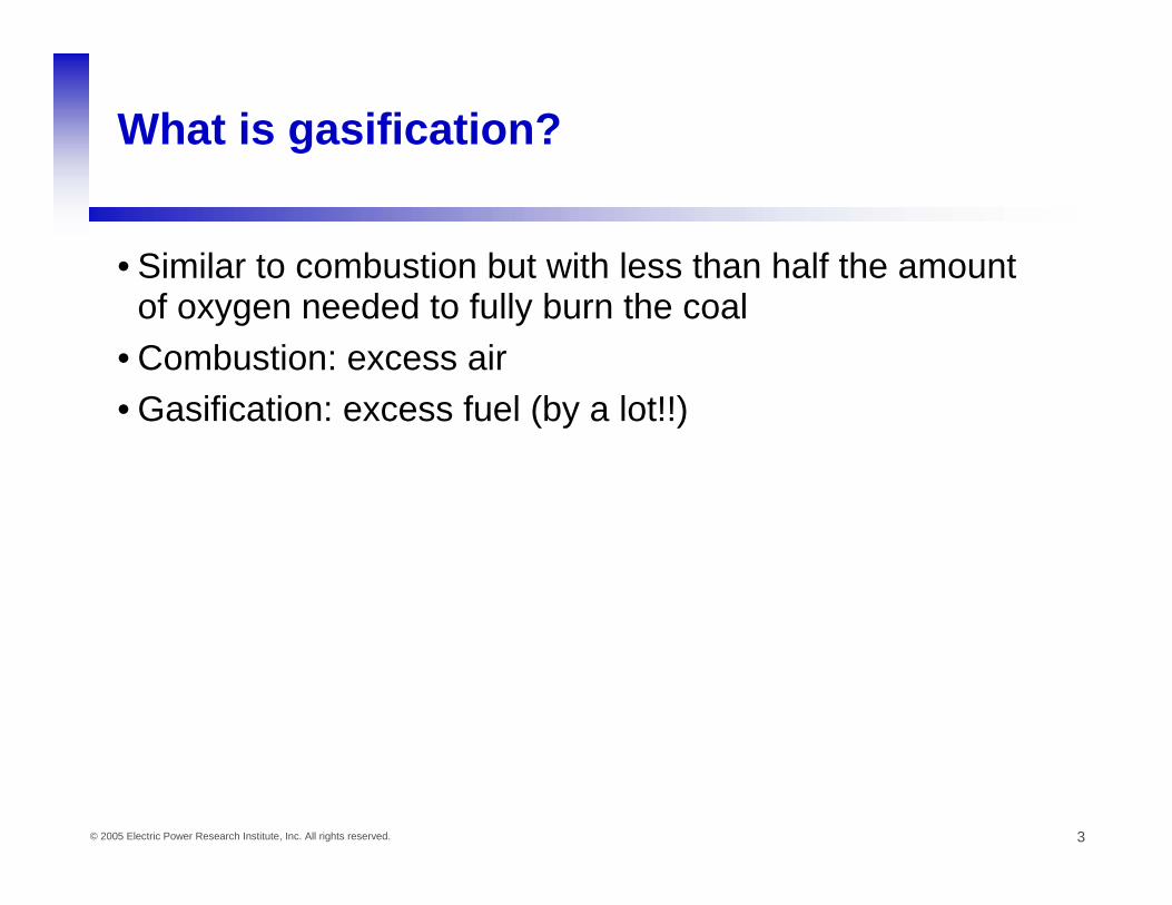
Combustion vs Gasification
• SO2 & SO3 must be scrubbed out of stack gas
• NOx controlled with low NOx burners and catalytic conversion (SCR)
• Large volume of flyash & sludge causes disposal issues
• Hg removed by contacting flue gas with activated carbon
• CO2 must be separated from stack gas
• H2S & COS are easily removed and converted to solid sulfur
• NH3 washes out of gas with water, thermal NOx controlled by diluent injection in CT
• Ash is converted to glassy slag which is inert and usable
• Hg removed by passing high pressure syngas thru activated carbon bed
• CO can be shifted to CO2 & removed from high pressure syngas

7© 2005 Electric Power Research Institute, Inc. All rights reserved.
Conventional Coal Plant
100 MW
15 MW
85 MW
40 MW
45 MW
40 % Efficiency

8© 2005 Electric Power Research Institute, Inc. All rights reserved.
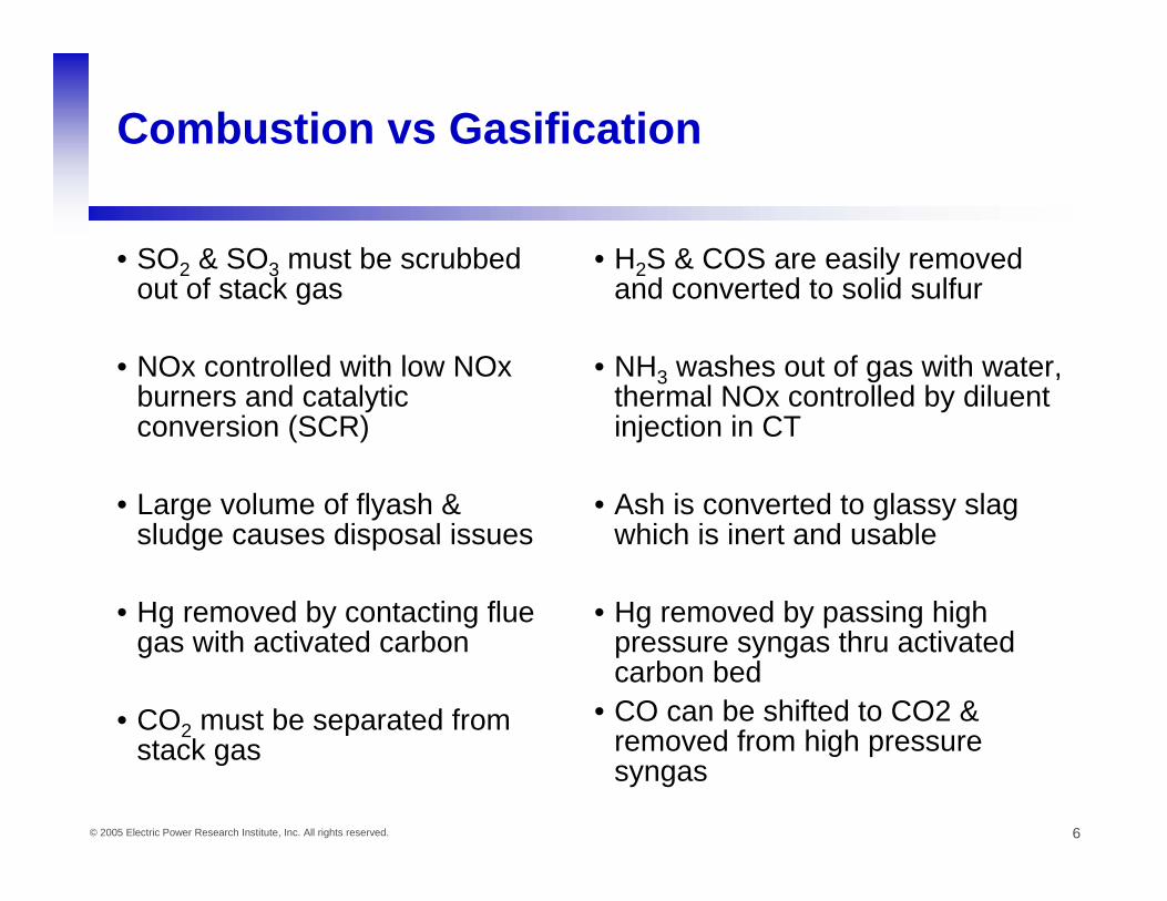
Combined Cycle
100 MW
Fuel
38 MW19 MW
62 MW
22 MW
21 MW to condenser
40 MW
19 + 38 = 57 MW 57% Efficiency!
9© 2005 Electric Power Research Institute, Inc. All rights reserved.
Combined Cycle

10© 2005 Electric Power Research Institute, Inc. All rights reserved.
15MW 80MW
30MW50MW
47MW22MW
9MW
Net Coal to Power: 30 + 22 – 9 = 43%
18MW
100MW

11© 2005 Electric Power Research Institute, Inc. All rights reserved.
Levelized Cost of Electricity(Assumes $1.50/MMbtu Coal, $5/MMBtu Natural Gas)
0
10
20
30
40
50
60
IGCC w/ spare IGCC w/o spare SCPC NGCC
Leve
lized
Cos
t of E
lect
ricity
($/M
W-h
r)
FuelO&MCapital

12© 2005 Electric Power Research Institute, Inc. All rights reserved.
IGCC with CO2 Removal and OptionalHydrogen Co-Production
O2 N2
Air
BFW
BFWSteam
Steam Turbine
HRSG
CoalPrep
Gas CoolingGasificationC + H2O = CO + H2
Sulfur and CO2
Removal
Air Separation
Unit
GasTurbine
Air
Hydrogen
CO2 to use or sequestrationSulfur
ShiftCO+ H2O = CO2 + H2
13© 2005 Electric Power Research Institute, Inc. All rights reserved.
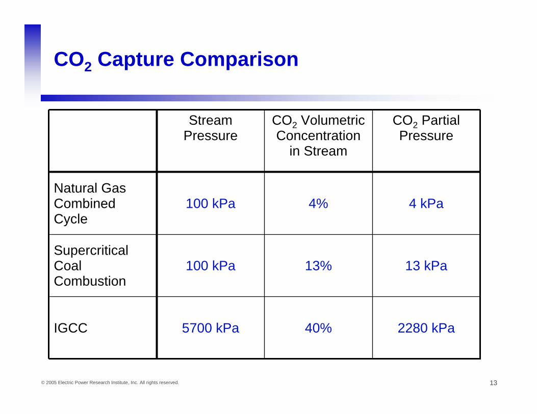
CO2 Capture Comparison
2280 kPa40%5700 kPaIGCC
13 kPa13%100 kPaSupercritical Coal Combustion
4 kPa4%100 kPaNatural Gas Combined Cycle
CO2 Partial Pressure
CO2 Volumetric Concentration
in Stream
Stream Pressure

14© 2005 Electric Power Research Institute, Inc. All rights reserved.
Costs of Electricity from New Fossil Fuel Power Plants with & without CO2 Capture(based on today’s technology)
0102030405060708090
NGCC F525 MW($3.50NG)
NGCC 525 MW($5 NG)
IGCC F520 MW
USC PC600 MW
COE $MWh with Capture& Sequestration
COE $/MWh with CO2Capture
COE $/MWh w/outCapture
$/M
Wh

15© 2005 Electric Power Research Institute, Inc. All rights reserved.
Existing Coal-based IGCCs
Wabash (Indiana)
Buggenum (NL)Polk (Florida)
Puertollano (Spain)
16© 2005 Electric Power Research Institute, Inc. All rights reserved.
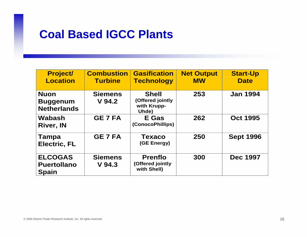
Coal Based IGCC Plants
Project/ Location
Combustion Turbine
Gasification Technology
Net Output MW
Start-Up Date
Nuon Buggenum Netherlands
Siemens V 94.2
Shell (Offered jointly with Krupp- Uhde)
253 Jan 1994
Wabash River, IN
GE 7 FA E Gas (ConocoPhillips)
262 Oct 1995
Tampa Electric, FL
GE 7 FA Texaco (GE Energy)
250 Sept 1996
ELCOGAS Puertollano Spain
Siemens V 94.3
Prenflo (Offered jointly with Shell)
300 Dec 1997
17© 2005 Electric Power Research Institute, Inc. All rights reserved.
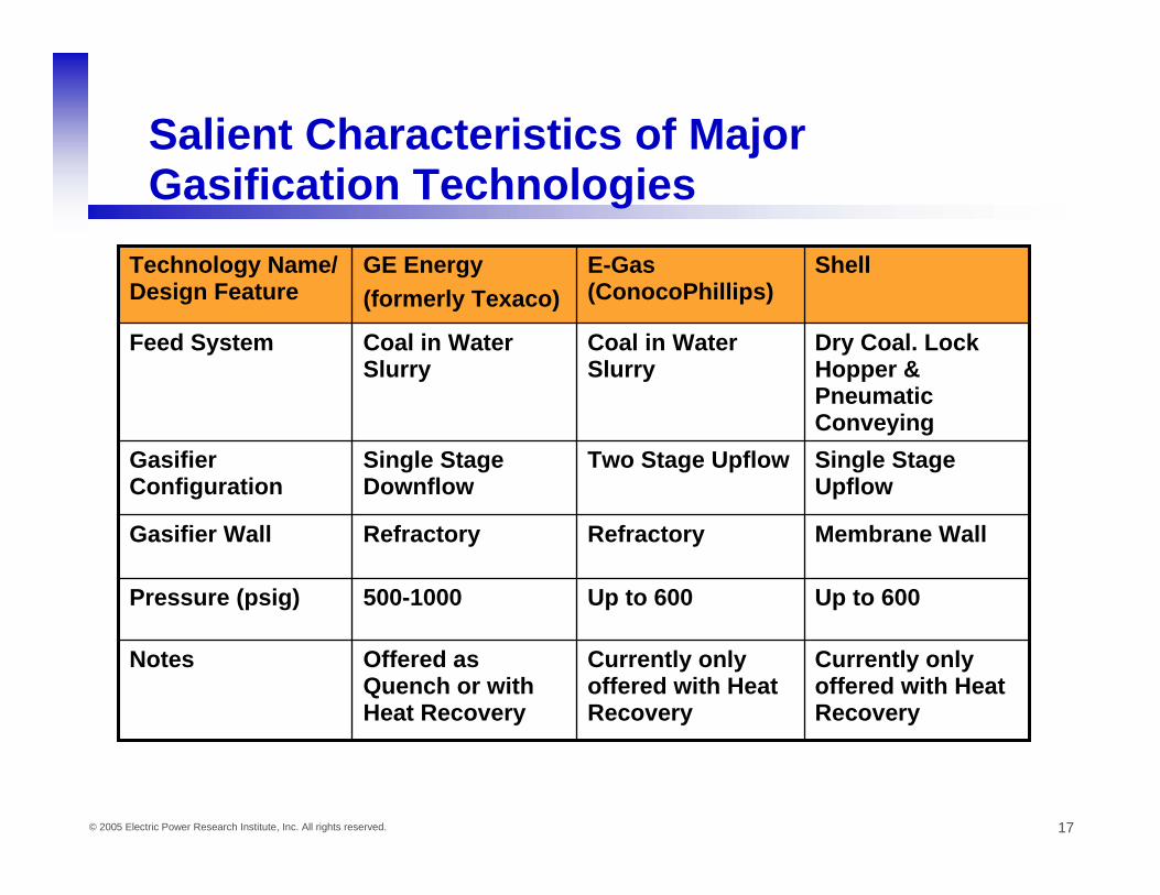
Salient Characteristics of Major Gasification Technologies
Up to 600Up to 600500-1000Pressure (psig)
Currently only offered with Heat Recovery
Currently only offered with Heat Recovery
Offered as Quench or with Heat Recovery
Notes
Membrane WallRefractoryRefractoryGasifier Wall
Single Stage Upflow
Two Stage UpflowSingle Stage Downflow
Gasifier Configuration
Dry Coal. Lock Hopper & Pneumatic Conveying
Coal in Water Slurry
Coal in Water Slurry
Feed System
ShellE-Gas (ConocoPhillips)
GE Energy(formerly Texaco)
Technology Name/ Design Feature

18© 2005 Electric Power Research Institute, Inc. All rights reserved.
GE Energy Quench Gasifier
Source: GE Energy
19© 2005 Electric Power Research Institute, Inc. All rights reserved.
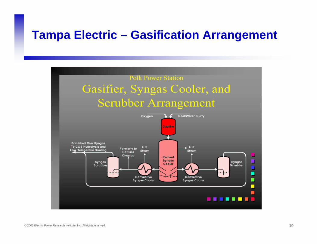
Tampa Electric – Gasification Arrangement

20© 2005 Electric Power Research Institute, Inc. All rights reserved.
E-Gas Gasifier—As used at Wabash IGCC(Technology now owned by ConocoPhillips)

21© 2005 Electric Power Research Institute, Inc. All rights reserved.
Shell Gasifier Cutaway
Coal & O2 Coal & O2
Syngas
Quench Gas
Slag
22© 2005 Electric Power Research Institute, Inc. All rights reserved.
Worldwide IGCC Experience
• Four coal based IGCC plants Tampa, Wabash, Buggenum and Puertollano.
• Eight operating IGCC plants based on Petroleum Residuals. Three more in construction. These plants represent considerable additional commercial operating experience for the many components that are common with coal based IGCC plants (ASUs, Gas clean up, Sulfur recovery, Combined Cycles, SCR etc).
• Cumulative Combustion Turbine experience on a wide variety of syngas compositions and heating values (range 100-350 Btu/SCF) is well over a million hours.
23© 2005 Electric Power Research Institute, Inc. All rights reserved.
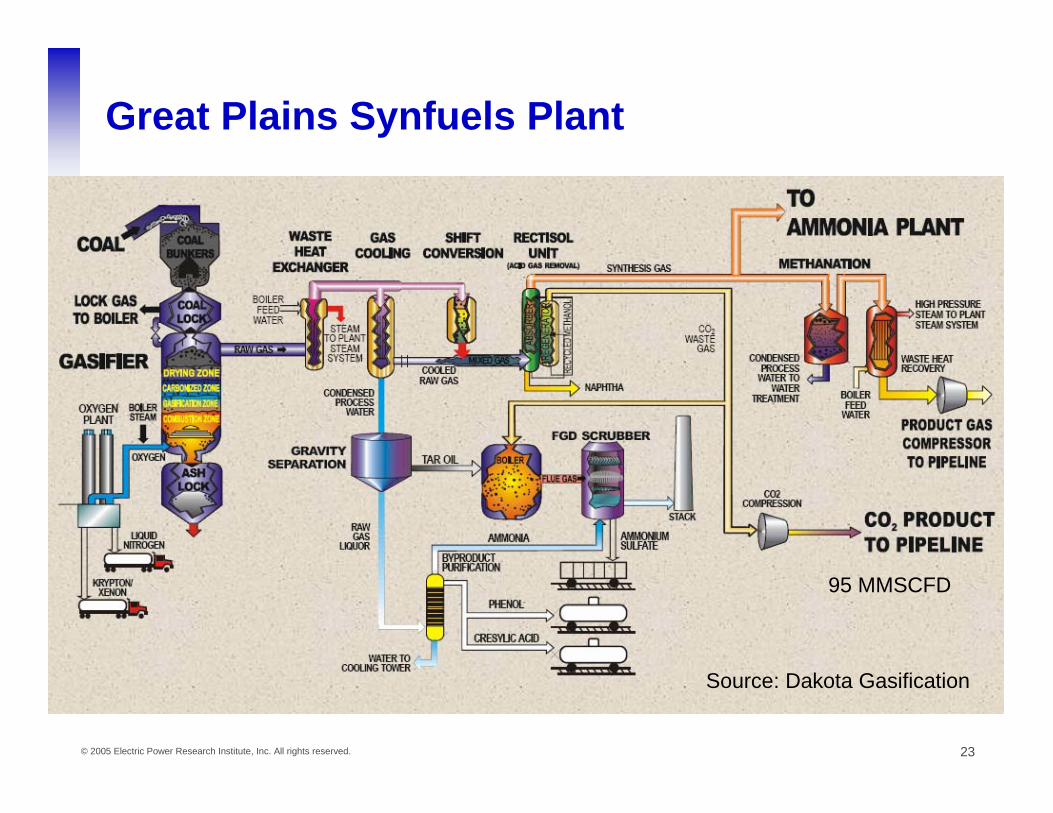
Great Plains Synfuels Plant
Source: Dakota Gasification
95 MMSCFD

24© 2005 Electric Power Research Institute, Inc. All rights reserved.
IGCC CO2 Recovery R&D Needs
• All the technology necessary for an IGCC with 90% CO2 capture has been demonstrated at commercial scale except:– An advanced (F class or better) combustion turbine
fired on near 100% H2• Current OEM restrictions on H2 content limit CO2 capture to
about 85%• Need to develop a CT which can accept the syngas
produced by 90% CO2 capture
25© 2005 Electric Power Research Institute, Inc. All rights reserved.
IGCC Demonstration Needs
• Even though all the different pieces of an IGCC with CO2capture have been demonstrated, they have never been demonstrated together in one plant– Water-Gas Shift of syngas and CO2 capture and
compression has been demonstrated at Great Plains Gasification
– Integration of gasification and combined cycles has been demonstrated at 4 large facilities
– Still need to demonstrate IGCC plus water-gas shift and CO2 capture and compression in an integrated plant to identify any operations and controls issues

26© 2005 Electric Power Research Institute, Inc. All rights reserved.
IGCC Improvement Opportunities
• Reduce ASU power consumption– New ASU – perhaps Ion Transfer Membrane (ITM)? – An ASU at 200-300°C would be nice.
• Gas separation membranes and processes that can operate at warmer temperatures and that can also reduce the auxiliary powerrequirements for separation and compression.
• Gas turbine redesign to recover the derated performance (efficiency) with hydrogen firing.
• Longer term possibilities such as the Clean Power Systems concept and Solid Oxide Fuel Cell with Oxygen Transfer Membrane on Anode gas would eliminate the need for shift and CO2 removal from the syngas since the flue gas is essentially CO2 and water.
27© 2005 Electric Power Research Institute, Inc. All rights reserved.
0.0%
10.0%
20.0%
30.0%
40.0%
50.0%
60.0%
70.0%
80.0%
90.0%
1styear
2ndyear
3rdyear
4thyear
5thyear
6thyear
7thyear
8thyear
9thyear
10thyear
11thyear
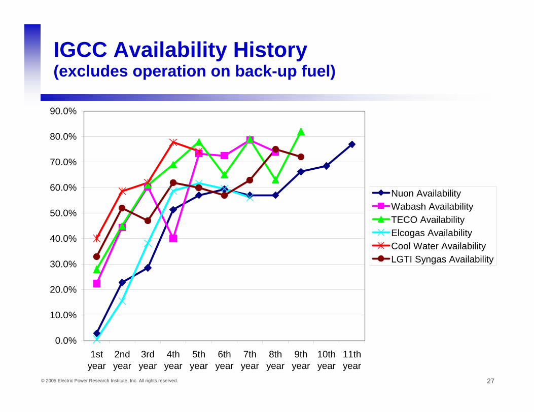
Nuon AvailabilityWabash AvailabilityTECO AvailabilityElcogas AvailabilityCool Water AvailabilityLGTI Syngas Availability
IGCC Availability History (excludes operation on back-up fuel)
28© 2005 Electric Power Research Institute, Inc. All rights reserved.
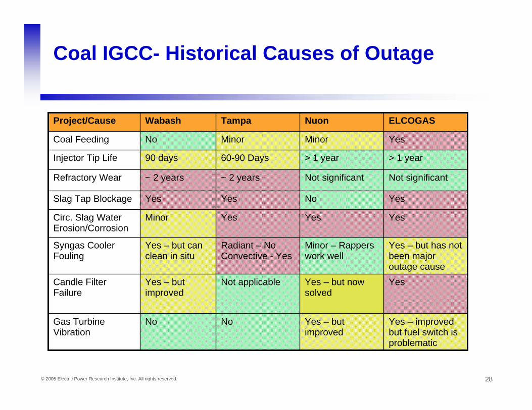
Coal IGCC- Historical Causes of Outage
Yes – improved but fuel switch is problematic
Yes – but improved
NoNoGas Turbine Vibration
YesYes – but now solved
Not applicableYes – but improved
Candle Filter Failure
Yes – but has not been major outage cause
Minor – Rappers work well
Radiant – No Convective - Yes
Yes – but can clean in situ
Syngas Cooler Fouling
YesYesYesMinorCirc. Slag Water Erosion/Corrosion
YesNoYesYesSlag Tap Blockage
Not significantNot significant ~ 2 years~ 2 yearsRefractory Wear
> 1 year> 1 year 60-90 Days90 days Injector Tip Life
YesMinor Minor NoCoal Feeding
ELCOGASNuonTampa WabashProject/Cause

29© 2005 Electric Power Research Institute, Inc. All rights reserved.
IGCC: Ideas to improve RAM
• Develop improved refractory improvement – (or improved flux to lower gasifier temperature and extend
refractory life)• Develop gasifier instrumentation to guide operations
– More reliable thermocouples and gasifier temperature measurement
– On line slag analysis to prevent plugging– On line pH measurement in circulating slag/ash loops – On line slurry analysis– Demonstrate rapid on-line syngas composition measurement
via laser adsorption spectroscopy• Research methods to prevent syngas cooler plugging/fouling• IGCC dynamic models & adaptation for operator training• Improved feed injectors• Reliability survey of existing gasification plants • More durable warm gas filter elements• CFD modeling of gasifiers

The End