Embed Size (px)
Citation preview
GT Simulator3Version1
SW1DNC-GTWK3-E
Integrated FA Software
Operating Manual for GT Works3


SAFETY PRECAUTIONS(Always read these precautions before using this equipment.)
Before using this product, please read this manual and the relevant manuals introduced in this manual
carefully and pay full attention to safety to handle the product correctly.
The precautions given in this manual are concerned with this product.
In this manual, the safety precautions are ranked as "WARNING" and "CAUTION".
Note that the caution level may lead to a serious accident according to the circumstances.
Always follow the instructions of both levels because they are important to personal safety.
Please save this manual to make it accessible when required and always forward it to the end user.
[Test Operation Precautions]
WARNING
GT Simulator3 is designed to simulate the actual GOT to debug created screens. However, we do
not guarantee the operations of the GOT and PLC CPU after debugging.
After performing debugging on GT Simulator2, connect the GOT and PLC CPU and perform ordinary
debugging before starting actual operation.
Not using the actual GOT and PLC CPU for debugging may result in accidents due to incorrect
outputs or malfunctions.
WARNING
CAUTION
Indicates that incorrect handling may cause hazardous conditions, resulting in death or severe injury.
CAUTION Indicates that incorrect handling may cause hazardous conditions, resulting in minor or moderate injury or property damage.
A - 1

CAUTIONS FOR USING THIS SOFTWARE
1. Required PC memory
The processing may be terminated by Microsoft Windows on a personal computer of which main memory capacity is less than 64M bytes. Make sure to secure the capacity of 64M bytes or more.
2. Free capacity of hard diskAt least 200M bytes of free capacity of virtual memory should be secured within hard disk to run this software.
The processing may be terminated by Windows, if free space of 200M bytes or more cannot be secured within hard disk while running GT Simulator2.Secure enough free capacity of virtual memory within hard disk space in order to run the software.When using the GT Simulator2 together with the GT Designer2, GX Developer or GX Simulator, the extra free capacity is required.For the free capacity required for using the GT Designer2, GX Developer or GX Simulator, refer to the following manual.
•GT Designer3 Version1 Screen Design Manual (Fundamentals)
•GX Developer Version Operating Manual (Startup)
•GX Simulator Version Operating Manual
3. Display of GT Simulator3 and GOTDisplay of GT Simulator3 may be different from display of GOT.Confirm for actual display of GOT on the GOT
A - 2

SAFETY PRECAUTIONS.........................................................................................................................A - 1
CAUTIONS FOR USING THIS SOFTWARE............................................................................................A - 2
INTRODUCTION ......................................................................................................................................A - 3
CONTENTS ..............................................................................................................................................A - 3
MANUALS.................................................................................................................................................A - 6
QUICK REFERENCE ...............................................................................................................................A - 8
ABBREVIATIONS AND GENERIC TERMS ...........................................................................................A - 10
HOW TO READ THIS MANUAL .............................................................................................................A - 15
1. OVERVIEW
1.1 Features........................................................................................................................................... 1 - 2
2. SYSTEM CONFIGURATION
2.1 System Configuration ...................................................................................................................... 2 - 1
2.2 Operating environment .................................................................................................................... 2 - 3
2.3 PLC CPUs that Can Be Simulated ................................................................................................. 2 - 5
2.4 Connection Cable ............................................................................................................................ 2 - 9
2.4.1 Connecting to QCPU or motion controller CPU (Q series) ................................................... 2 - 9
2.4.2 Connecting to LCPU........................................................................................................... 2 - 11
2.4.3 Connecting to QnACPU, ACPU, motion controller CPU (A series) and FXCPU................ 2 - 12
2.4.4 Connecting to MELSECNET/H remote I/O station ............................................................. 2 - 15
2.4.5 Connecting to CC-Link IE Field Network head module ...................................................... 2 - 15
2.4.6 Connecting to MELDAS C6/C64 ........................................................................................ 2 - 16
2.4.7 Connecting to Omron PLC CPU......................................................................................... 2 - 17
3. SPECIFICATIONS
3.1 GOT that Can Be Simulated ............................................................................................................ 3 - 1
3.2 Functions that cannot be simulated ................................................................................................. 3 - 3
3.3 Precautions.................................................................................................................................... 3 - 13
3.3.1 Precautions for using the GT Simulator3............................................................................ 3 - 13
3.3.2 Precautions for connecting to GX Simulator or GX Simulator2 .......................................... 3 - 21
3.3.3 Precautions for connecting PLC CPU ................................................................................ 3 - 22
3.4 Device Ranges that Can Be Simulated ......................................................................................... 3 - 23
3.4.1 Connecting to PLC CPU..................................................................................................... 3 - 23
3.4.2 Connecting to GX Simulator or GX Simlator2 .................................................................... 3 - 24
INTRODUCTION
Thank you for choosing Mitsubishi Graphic Operation Terminal (Mitsubishi GOT).
Read this manual and make sure you understand the functions and performance of the GOT thoroughly in
advance to ensure correct use.
CONTENTS
A - 3

4. SCREEN CONFIGURATION OF GT SIMULATOR3
4.1 Screen Configuration and Basic Operation ..................................................................................... 4 - 1
4.1.1 Screen configuration............................................................................................................. 4 - 1
4.1.2 Basic operation ..................................................................................................................... 4 - 2
4.2 Menu Bar ......................................................................................................................................... 4 - 3
4.3 Tool Bar ........................................................................................................................................... 4 - 4
4.4 How to use HELP ............................................................................................................................ 4 - 6
5. GT SIMULATOR3 OPERATING METHOD
5.1 Operating Procedure ....................................................................................................................... 5 - 1
5.2 Starting GT Simulator3 .................................................................................................................... 5 - 3
5.3 Option Setting .................................................................................................................................. 5 - 4
5.3.1 Setting items (GOT1000 series simulator)............................................................................ 5 - 4
5.3.2 Setting items (GOT-A900 series simulator) ........................................................................ 5 - 11
5.4 Executing a simulation................................................................................................................... 5 - 15
5.5 Opening the Project ....................................................................................................................... 5 - 16
5.5.1 Open the GT Designer3 Project ......................................................................................... 5 - 16
5.5.2 Open the GT Designer3 compressed file ........................................................................... 5 - 18
5.5.3 Open the GT Designer2 file ................................................................................................ 5 - 20
5.6 Setting Reading Data (GOT-A900 Series Simulator) .................................................................... 5 - 22
5.7 Simulating Operation ..................................................................................................................... 5 - 26
5.8 Exiting from GT Simulator3............................................................................................................ 5 - 26
6. FUNCTIONS OF GT SIMULATOR3
6.1 Snap Shot ........................................................................................................................................ 6 - 1
6.2 Print ................................................................................................................................................. 6 - 2
6.2.1 Printing.................................................................................................................................. 6 - 2
6.2.2 Performing print preview....................................................................................................... 6 - 3
6.2.3 Performing page setup ......................................................................................................... 6 - 4
6.2.4 Performing print setup .......................................................................................................... 6 - 4
6.3 Property ........................................................................................................................................... 6 - 5
6.4 System Alarm .................................................................................................................................. 6 - 6
6.5 Script Error....................................................................................................................................... 6 - 7
6.6 Object Script Error ........................................................................................................................... 6 - 8
6.7 Full Screen Mode Function (GT16**-X, GT15**-X only) .................................................................. 6 - 9
7. DEVICE MONITOR
7.1 Overview.......................................................................................................................................... 7 - 1
7.2 Precautions...................................................................................................................................... 7 - 2
7.3 Screen Configuration of Device Monitor .......................................................................................... 7 - 3
7.3.1 Screen configuration and various Tools .............................................................................. 7 - 3
7.3.2 Menu Bar .............................................................................................................................. 7 - 4
7.3.3 Tool Bar ................................................................................................................................ 7 - 5
7.3.4 Device Monitor screen .......................................................................................................... 7 - 6
7.3.5 Status Bar ............................................................................................................................. 7 - 8
A - 4

7.4 Device Monitor Operation Method ................................................................................................... 7 - 9
7.4.1 Starting Device Monitor ...................................................................................................... 7 - 10
7.4.2 Stopping and restarting the monitor ................................................................................... 7 - 11
7.4.3 Exit Device Monitor............................................................................................................. 7 - 11
7.5 Device Monitor Functions .............................................................................................................. 7 - 12
7.5.1 Sorting the data .................................................................................................................. 7 - 12
7.5.2 Testing device value........................................................................................................... 7 - 13
7.5.3 Registering/Deleting device (Free Registration screen) ..................................................... 7 - 14
7.5.4 Displaying screens with cascade/tile .................................................................................. 7 - 15
7.5.5 Changing Device Monitor screen ....................................................................................... 7 - 16
7.6 Setting Display............................................................................................................................... 7 - 17
7.6.1 Setting items....................................................................................................................... 7 - 17
8. TROUBLESHOOTING
8.1 Troubleshooting for File Save Problems.......................................................................................... 8 - 1
8.2 Error Message (GOT1000 series simulator).................................................................................... 8 - 1
8.3 Error Message (GOT-A900 series simulator) .................................................................................. 8 - 6
APPENDICES
Appendix1 Applicable Project Data .......................................................................................................App - 1
INDEX
REVISIONS
A - 5

MANUALS
The following table lists the manual relevant to this product.Refer to each manual for any purpose.
Screen creation software manuals
Connection manuals
Extended and option function manuals
GT SoftGOT1000 manuals
Manual Name PackagingManual Number
(Model code)
GT Works3 Version1 Installation Procedure Manual Enclosed in product -
GT Designer3 Version1 Screen Design Manual (Fundamentals) 1/2, 2/2 Stored in CD-ROMSH-080866ENG
(1D7MB9)
GT Designer3 Version1 Screen Design Manual (Functions) 1/2, 2/2 Stored in CD-ROMSH-080867ENG
(1D7MC1)
GT Simulator3 Version1 Operating Manual for GT Works3 Stored in CD-ROMSH-080861ENG
(1D7MB1)
GT Converter2 Version3 Operating Manual for GT Works3 Stored in CD-ROMSH-080862ENG
(1D7MB2)
Manual Name PackagingManual Number
(Model code)
GOT1000 Series Connection Manual (Mitsubishi Products) for GT Works3 Stored in CD-ROMSH-080868ENG
(1D7MC2)
GOT1000 Series Connection Manual (Non-Mitsubishi Products 1) for GT Works3 Stored in CD-ROMSH-080869ENG
(1D7MC3)
GOT1000 Series Connection Manual (Non-Mitsubishi Products 2) for GT Works3 Stored in CD-ROMSH-080870ENG
(1D7MC4)
GOT1000 Series Connection Manual (Microcomputer, MODBUS Products, Peripherals) for GT
Works3Stored in CD-ROM
SH-080871ENG
(1D7MC5)
Manual Name PackagingManual Number
(Model code)
GOT1000 Series Gateway Functions Manual for GT Works3 Stored in CD-ROMSH-080858ENG
(1D7MA7)
GOT1000 Series MES Interface Function Manual for GT Works3 Stored in CD-ROMSH-080859ENG
(1D7MA8)
GOT1000 Series User's Manual (Extended Functions, Option Functions) for GT Works3 Stored in CD-ROMSH-080863ENG
(1D7MB3)
Manual Name PackagingManual Number
(Model code)
GT SoftGOT1000 Version3 Operating Manual for GT Works3 Stored in CD-ROMSH-080860ENG
(1D7MA9)
A - 6
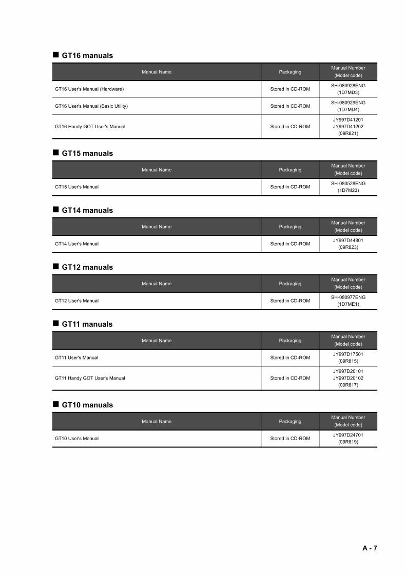
GT16 manuals
GT15 manuals
GT14 manuals
GT12 manuals
GT11 manuals
GT10 manuals
Manual Name PackagingManual Number
(Model code)
GT16 User's Manual (Hardware) Stored in CD-ROMSH-080928ENG
(1D7MD3)
GT16 User's Manual (Basic Utility) Stored in CD-ROMSH-080929ENG
(1D7MD4)
GT16 Handy GOT User's Manual Stored in CD-ROM
JY997D41201
JY997D41202
(09R821)
Manual Name PackagingManual Number
(Model code)
GT15 User's Manual Stored in CD-ROMSH-080528ENG
(1D7M23)
Manual Name PackagingManual Number
(Model code)
GT14 User's Manual Stored in CD-ROMJY997D44801
(09R823)
Manual Name PackagingManual Number
(Model code)
GT12 User's Manual Stored in CD-ROMSH-080977ENG
(1D7ME1)
Manual Name PackagingManual Number
(Model code)
GT11 User's Manual Stored in CD-ROMJY997D17501
(09R815)
GT11 Handy GOT User's Manual Stored in CD-ROM
JY997D20101
JY997D20102
(09R817)
Manual Name PackagingManual Number
(Model code)
GT10 User's Manual Stored in CD-ROMJY997D24701
(09R819)
A - 7

QUICK REFERENCE
Creating a project
Connecting a controller to the GOT
Transferring data to the GOT
Obtaining the specifications and operation methods of GT Designer3
GT Designer3 Version1 Screen Design Manual
(Fundamentals) 1/2, 2/2
Setting available functions on GT Designer3
Creating a screen displayed on the GOT
Obtaining useful functions to increase efficiency of drawing
Setting details for figures and objects
GT Designer3 Version1 Screen Design Manual (Functions)
1/2, 2/2Setting functions for the data collection or trigger action
Setting functions to use peripheral devices
Simulating a created project on a personal computer GT Simulator3 Version1 Operating Manual for GT Works3
Obtaining information of Mitsubishi products applicable to the GOT
GOT1000 Series Connection Manual (Mitsubishi Products) for
GT Works3
Connecting Mitsubishi products to the GOT
Connecting multiple controllersto one GOT (Multi-channel function)
Establishing communication between a personal computer and a
controller via the GOT (FA transparent function)
Obtaining information of Non-Mitsubishi products applicable to the GOT • GOT1000 Series Connection Manual (Non-Mitsubishi
Products 1) for GT Works3
• GOT1000 Series Connection Manual (Non-Mitsubishi
Products 2) for GT Works3Connecting Non-Mitsubishi products to the GOT
Obtaining information of peripheral devices applicable to the GOTGOT1000 Series Connection Manual (Microcomputer,
MODBUS Products, Peripherals) for GT Works3Connecting peripheral devices including a barcode reader to the GOT
Writing data to the GOT
GT Designer3 Version1 Screen Design Manual
(Fundamentals) 1/2, 2/2Reading data from the GOT
Verifying a editing project to a GOT project
A - 8

Others
Obtaining specifications (including part names, external dimensions, and
options) of each GOT
• GT16 User's Manual (Hardware)
• GT16 Handy GOT User's Manual
• GT15 User's Manual
• GT14 User's Manual
• GT12 User's Manual
• GT11 User's Manual
• GT11 Handy GOT User's Manual
• GT10 User's Manual
Installing the GOT
Operating the utility
• GT16 User's Manual (Basic Utility)
• GT16 Handy GOT User's Manual
• GT15 User's Manual
• GT14 User's Manual
• GT12 User's Manual
• GT11 User's Manual
• GT11 Handy GOT User's Manual
• GT10 User's Manual
Configuring the gateway function GOT1000 Series Gateway Functions Manual for GT Works3
Configuring the MES interface functionGOT1000 Series MES Interface Function Manual for GT
Works3
Configuring the extended function and option functionGOT1000 Series User's Manual (Extended Functions, Option
Functions) for GT Works3
Using a personal computer as the GOT GT SoftGOT1000 Version3 Operating Manual for GT Works3
A - 9

ABBREVIATIONS AND GENERIC TERMS
GOT
Abbreviations and generic terms Description
GOT1000
Series
GT1695 GT1695M-X Abbreviation of GT1695M-XTBA, GT1695M-XTBD
GT1685 GT1685M-S Abbreviation of GT1685M-STBA, GT1685M-STBD
GT1675
GT1675M-S Abbreviation of GT1675M-STBA, GT1675M-STBD
GT1675M-V Abbreviation of GT1675M-VTBA, GT1675M-VTBD
GT1675-VN Abbreviation of GT1675-VNBA, GT1675-VNBD
GT1672 GT1672-VN Abbreviation of GT1672-VNBA, GT1672-VNBD
GT1665GT1665M-S Abbreviation of GT1665M-STBA, GT1665M-STBD
GT1665M-V Abbreviation of GT1665M-VTBA, GT1665M-VTBD
GT1662 GT1662-VN Abbreviation of GT1662-VNBA, GT1662-VNBD
GT1655 GT1655-V Abbreviation of GT1655-VTBD
GT16 Abbreviation of GT1695, GT1685, GT1675, GT1672, GT1665, GT1662, GT1655, GT16 Handy GOT
GT1595 GT1595-X Abbreviation of GT1595-XTBA, GT1595-XTBD
GT1585GT1585V-S Abbreviation of GT1585V-STBA, GT1585V-STBD
GT1585-S Abbreviation of GT1585-STBA, GT1585-STBD
GT157
GT1575V-S Abbreviation of GT1575V-STBA, GT1575V-STBD
GT1575-S Abbreviation of GT1575-STBA, GT1575-STBD
GT1575-V Abbreviation of GT1575-VTBA, GT1575-VTBD
GT1575-VN Abbreviation of GT1575-VNBA, GT1575-VNBD
GT1572-VN Abbreviation of GT1572-VNBA, GT1572-VNBD
GT156GT1565-V Abbreviation of GT1565-VTBA, GT1565-VTBD
GT1562-VN Abbreviation of GT1562-VNBA, GT1562-VNBD
GT155
GT1555-V Abbreviation of GT1555-VTBD
GT1555-Q Abbreviation of GT1555-QTBD, GT1555-QSBD
GT1550-Q Abbreviation of GT1550-QLBD
GT15 Abbreviation of GT1595, GT1585, GT157 , GT156 , GT155
GT145GT1455-Q Abbreviation of GT1455-QTBDE, GT1455-QTBD
GT1450-Q Abbreviation of GT1450-QLBDE, GT1450-QLBD
GT14 Abbreviation of GT1455-Q, GT1450-Q
GT1275 GT1275-V Abbreviation of GT1275-VNBA, GT1275-VNBD
GT1265 GT1265-V Abbreviation of GT1265-VNBA, GT1265-VNBD
GT12 Abbreviation of GT1275, GT1265
GT115GT1155-Q
Abbreviation of GT1155-QTBDQ, GT1155-QSBDQ, GT1155-QTBDA, GT1155-QSBDA,
GT1155-QTBD, GT1155-QSBD
GT1150-Q Abbreviation of GT1150-QLBDQ, GT1150-QLBDA, GT1150-QLBD
GT11 Abbreviation of GT115 , GT11 Handy GOT,
GT105GT1055-Q Abbreviation of GT1055-QSBD
GT1050-Q Abbreviation of GT1050-QBBD
GT104GT1045-Q Abbreviation of GT1045-QSBD
GT1040-Q Abbreviation of GT1040-QBBD
GT1030
Abbreviation of GT1030-LBD, GT1030-LBD2, GT1030-LBL, GT1030-LBDW, GT1030-LBDW2,
GT1030-LBLW, GT1030-LWD, GT1030-LWD2, GT1030-LWL, GT1030-LWDW, GT1030-LWDW2,
GT1030-LWLW, GT1030-HBD, GT1030-HBD2, GT1030-HBL, GT1030-HBDW, GT1030-HBDW2,
GT1030-HBLW, GT1030-HWD, GT1030-HWD2, GT1030-HWL, GT1030-HWDW, GT1030-HWDW2,
GT1030-HWLW
GT1020
Abbreviation of GT1020-LBD, GT1020-LBD2, GT1020-LBL, GT1020-LBDW, GT1020-LBDW2,
GT1020-LBLW, GT1020-LWD, GT1020LWD2, GT1020-LWL, GT1020-LWDW, GT1020-LWDW2,
GT1020-LWLW
GT10 Abbreviation of GT105 , GT104 , GT1030, GT1020
A - 10
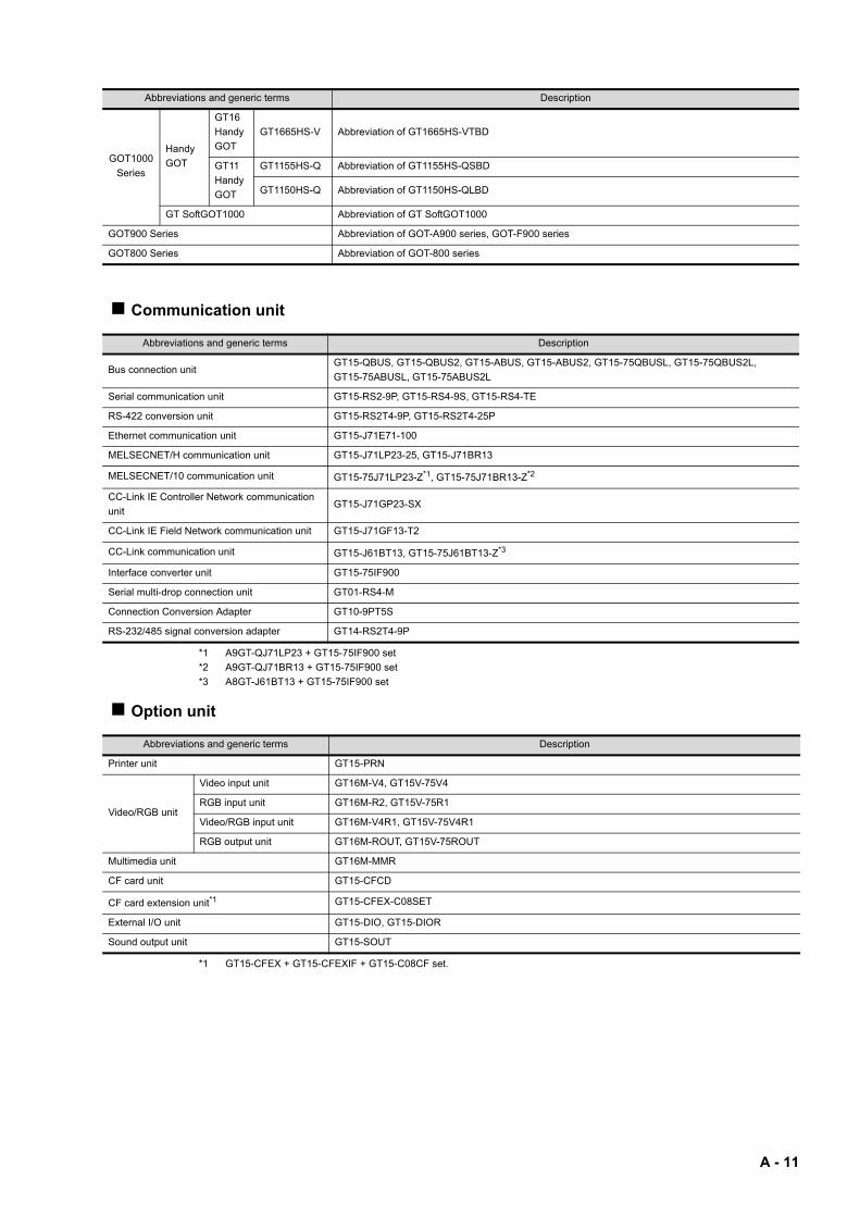
Communication unit
*1 A9GT-QJ71LP23 + GT15-75IF900 set
*2 A9GT-QJ71BR13 + GT15-75IF900 set
*3 A8GT-J61BT13 + GT15-75IF900 set
Option unit
*1 GT15-CFEX + GT15-CFEXIF + GT15-C08CF set.
GOT1000
Series
Handy
GOT
GT16
Handy
GOT
GT1665HS-V Abbreviation of GT1665HS-VTBD
GT11
Handy
GOT
GT1155HS-Q Abbreviation of GT1155HS-QSBD
GT1150HS-Q Abbreviation of GT1150HS-QLBD
GT SoftGOT1000 Abbreviation of GT SoftGOT1000
GOT900 Series Abbreviation of GOT-A900 series, GOT-F900 series
GOT800 Series Abbreviation of GOT-800 series
Abbreviations and generic terms Description
Bus connection unitGT15-QBUS, GT15-QBUS2, GT15-ABUS, GT15-ABUS2, GT15-75QBUSL, GT15-75QBUS2L,
GT15-75ABUSL, GT15-75ABUS2L
Serial communication unit GT15-RS2-9P, GT15-RS4-9S, GT15-RS4-TE
RS-422 conversion unit GT15-RS2T4-9P, GT15-RS2T4-25P
Ethernet communication unit GT15-J71E71-100
MELSECNET/H communication unit GT15-J71LP23-25, GT15-J71BR13
MELSECNET/10 communication unit GT15-75J71LP23-Z*1, GT15-75J71BR13-Z*2
CC-Link IE Controller Network communication
unitGT15-J71GP23-SX
CC-Link IE Field Network communication unit GT15-J71GF13-T2
CC-Link communication unit GT15-J61BT13, GT15-75J61BT13-Z*3
Interface converter unit GT15-75IF900
Serial multi-drop connection unit GT01-RS4-M
Connection Conversion Adapter GT10-9PT5S
RS-232/485 signal conversion adapter GT14-RS2T4-9P
Abbreviations and generic terms Description
Printer unit GT15-PRN
Video/RGB unit
Video input unit GT16M-V4, GT15V-75V4
RGB input unit GT16M-R2, GT15V-75R1
Video/RGB input unit GT16M-V4R1, GT15V-75V4R1
RGB output unit GT16M-ROUT, GT15V-75ROUT
Multimedia unit GT16M-MMR
CF card unit GT15-CFCD
CF card extension unit*1 GT15-CFEX-C08SET
External I/O unit GT15-DIO, GT15-DIOR
Sound output unit GT15-SOUT
Abbreviations and generic terms Description
A - 11

Option
Abbreviations and generic terms Description
Memory cardCF card
GT05-MEM-16MC, GT05-MEM-32MC, GT05-MEM-64MC, GT05-MEM-128MC,
GT05-MEM-256MC, GT05-MEM-512MC, GT05-MEM-1GC, GT05-MEM-2GC,
GT05-MEM-4GC, GT05-MEM-8GC, GT05-MEM-16GC
SD card L1MEM-2GBSD, L1MEM-4GBSD
Memory card adaptor GT05-MEM-ADPC
Option function boardGT16-MESB, GT15-FNB, GT15-QFNB, GT15-QFNB16M,
GT15-QFNB32M, GT15-QFNB48M, GT11-50FNB, GT15-MESB48M
Battery GT15-BAT, GT11-50BAT
Protective Sheet
For GT16
GT16-90PSCB, GT16-90PSGB, GT16-90PSCW, GT16-90PSGW,
GT16-80PSCB, GT16-80PSGB, GT16-80PSCW, GT16-80PSGW,
GT16-70PSCB, GT16-70PSGB, GT16-70PSCW, GT16-70PSGW,
GT16-60PSCB, GT16-60PSGB, GT16-60PSCW, GT16-60PSGW,
GT16-50PSCB, GT16-50PSGB, GT16-50PSCW, GT16-50PSGW,
GT16-90PSCB-012, GT16-80PSCB-012, GT16-70PSCB-012,
GT16-60PSCB-012, GT16-50PSCB-012, GT16H-60PSC
For GT15
GT15-90PSCB, GT15-90PSGB, GT15-90PSCW, GT15-90PSGW,
GT15-80PSCB, GT15-80PSGB, GT15-80PSCW, GT15-80PSGW,
GT15-70PSCB, GT15-70PSGB, GT15-70PSCW, GT15-70PSGW,
GT15-60PSCB, GT15-60PSGB, GT15-60PSCW, GT15-60PSGW,
GT15-50PSCB, GT15-50PSGB, GT15-50PSCW, GT15-50PSGW
For GT14 GT14-50PSCB, GT14-50PSGB, GT14-50PSCW, GT14-50PSGW
For GT12 GT11-70PSCB, GT11-65PSCB
For GT11GT11-50PSCB, GT11-50PSGB, GT11-50PSCW, GT11-50PSGW,
GT11H-50PSC
For GT10
GT10-50PSCB, GT10-50PSGB, GT10-50PSCW, GT10-50PSGW,
GT10-40PSCB, GT10-40PSGB, GT10-40PSCW, GT10-40PSGW,
GT10-30PSCB, GT10-30PSGB, GT10-30PSCW, GT10-30PSGW,
GT10-20PSCB, GT10-20PSGB, GT10-20PSCW, GT10-20PSGW
Protective cover for oilGT05-90PCO, GT05-80PCO, GT05-70PCO, GT05-60PCO, GT05-50PCO,
GT16-50PCO, GT10-40PCO, GT10-30PCO, GT10-20PCO
USB environmental protection cover GT16-UCOV, GT16-50UCOV, GT15-UCOV, GT14-50UCOV, GT11-50UCOV
Stand GT15-90STAND, GT15-80STAND, GT15-70STAND, A9GT-50STAND, GT05-50STAND
AttachmentGT15-70ATT-98, GT15-70ATT-87, GT15-60ATT-97, GT15-60ATT-96,
GT15-60ATT-87, GT15-60ATT-77, GT15-50ATT-95W, GT15-50ATT-85
Backlight
GT16-90XLTT, GT16-80SLTT, GT16-70SLTT, GT16-70VLTT, GT16-70VLTTA, GT16-70VLTN,
GT16-60SLTT, GT16-60VLTT, GT16-60VLTN, GT15-90XLTT, GT15-80SLTT, GT15-70SLTT,
GT15-70VLTT, GT15-70VLTN, GT15-60VLTT, GT15-60VLTN
Multi-color display board GT15-XHNB, GT15-VHNB
Connector conversion box GT11H-CNB-37S, GT16H-CNB-42S
Emergency stop sw guard cover GT11H-50ESCOV, GT16H-60ESCOV
Memory loader GT10-LDR
Memory board GT10-50FMB
Panel-mounted USB port extension GT14-C10EXUSB-4S, GT10-C10EXUSB-5S
A - 12

Software
License key (for GT SoftGOT1000)
Abbreviations and generic terms Description
GT Works3 Abbreviation of the SW DNC-GTWK3-E and SW DNC-GTWK3-EA
GT Designer3 Abbreviation of screen drawing software GT Designer3 for GOT1000 series
GT Simulator3 Abbreviation of screen simulator GT Simulator3 for GOT1000/GOT900 series
GT SoftGOT1000 Abbreviation of monitoring software GT SoftGOT1000
GT Converter2 Abbreviation of data conversion software GT Converter2 for GOT1000/GOT900 series
GT Designer2 Classic Abbreviation of screen drawing software GT Designer2 Classic for GOT900 series
GT Designer2 Abbreviation of screen drawing software GT Designer2 for GOT1000/GOT900 series
iQ Works Abbreviation of iQ Platform compatible engineering environment MELSOFT iQ Works
MELSOFT NavigatorGeneric term for integrated development environment software included in the SW DNC-IQWK (iQ
Platform compatible engineering environment MELSOFT iQ Works)
GX Works2Abbreviation of SW DNC-GXW2-E and SW DNC-GXW2-EA type programmable controller
engineering software
GX Simulator2 Abbreviation of GX Works2 with the simulation function
GX SimulatorAbbreviation of SW D5C-LLT-E(-EV) type ladder logic test tool function software packages
(SW5D5C-LLT (-EV) or later versions)
GX Developer Abbreviation of SW D5C-GPPW-E(-EV)/SW D5F-GPPW-E type software package
GX LogViewer Abbreviation of SW DNN-VIEWER-E type software package
PX Developer Abbreviation of SW D5C-FBDQ-E type FBD software package for process control
MT Works2Abbreviation of motion controller engineering environment MELSOFT MT Works2
(SW DNC-MTW2-E)
MT Developer Abbreviation of SW RNC-GSV type integrated start-up support software for motion controller Q series
MR Configurator2 Abbreviation of SW DNC-MRC2-E type Servo Configuration Software
MR Configurator Abbreviation of MRZJW -SETUP E type Servo Configuration Software
FR Configurator Abbreviation of Inverter Setup Software (FR-SW -SETUP-WE)
NC Configurator Abbreviation of CNC parameter setting support tool NC Configurator
FX Configurator-FPAbbreviation of parameter setting, monitoring, and testing software packages for FX3U-20SSC-H
(SW D5C-FXSSC-E)
FX3U-ENET-L Configuration tool Abbreviation of FX3U-ENET-L type Ethernet module setting software (SW1D5-FXENETL-E)
RT ToolBox2 Abbreviation of robot program creation software (3D-11C-WINE)
MX Component Abbreviation of MX Component Version (SW D5C-ACT-E, SW D5C-ACT-EA)
MX Sheet Abbreviation of MX Sheet Version (SW D5C-SHEET-E, SW D5C-SHEET-EA)
LCPU Logging Configuration Tool Abbreviation of LCPU Logging Configuration Tool (SW1DNN-LLUTL-E)
Abbreviations and generic terms Description
License GT15-SGTKEY-U, GT15-SGTKEY-P
A - 13
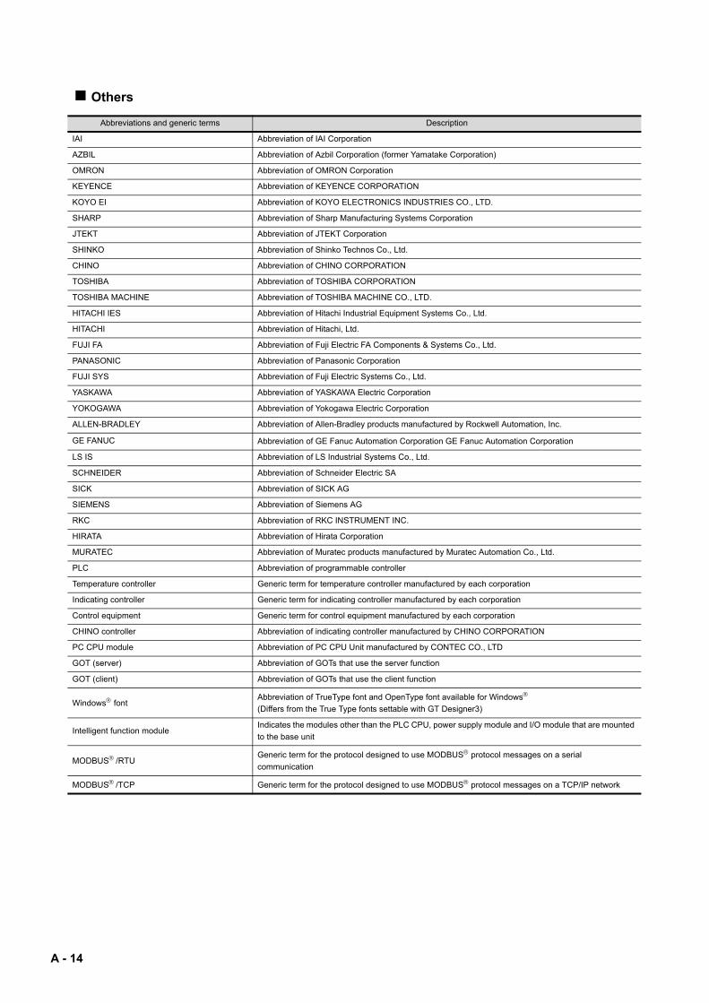
Others
Abbreviations and generic terms Description
IAI Abbreviation of IAI Corporation
AZBIL Abbreviation of Azbil Corporation (former Yamatake Corporation)
OMRON Abbreviation of OMRON Corporation
KEYENCE Abbreviation of KEYENCE CORPORATION
KOYO EI Abbreviation of KOYO ELECTRONICS INDUSTRIES CO., LTD.
SHARP Abbreviation of Sharp Manufacturing Systems Corporation
JTEKT Abbreviation of JTEKT Corporation
SHINKO Abbreviation of Shinko Technos Co., Ltd.
CHINO Abbreviation of CHINO CORPORATION
TOSHIBA Abbreviation of TOSHIBA CORPORATION
TOSHIBA MACHINE Abbreviation of TOSHIBA MACHINE CO., LTD.
HITACHI IES Abbreviation of Hitachi Industrial Equipment Systems Co., Ltd.
HITACHI Abbreviation of Hitachi, Ltd.
FUJI FA Abbreviation of Fuji Electric FA Components & Systems Co., Ltd.
PANASONIC Abbreviation of Panasonic Corporation
FUJI SYS Abbreviation of Fuji Electric Systems Co., Ltd.
YASKAWA Abbreviation of YASKAWA Electric Corporation
YOKOGAWA Abbreviation of Yokogawa Electric Corporation
ALLEN-BRADLEY Abbreviation of Allen-Bradley products manufactured by Rockwell Automation, Inc.
GE FANUC Abbreviation of GE Fanuc Automation Corporation GE Fanuc Automation Corporation
LS IS Abbreviation of LS Industrial Systems Co., Ltd.
SCHNEIDER Abbreviation of Schneider Electric SA
SICK Abbreviation of SICK AG
SIEMENS Abbreviation of Siemens AG
RKC Abbreviation of RKC INSTRUMENT INC.
HIRATA Abbreviation of Hirata Corporation
MURATEC Abbreviation of Muratec products manufactured by Muratec Automation Co., Ltd.
PLC Abbreviation of programmable controller
Temperature controller Generic term for temperature controller manufactured by each corporation
Indicating controller Generic term for indicating controller manufactured by each corporation
Control equipment Generic term for control equipment manufactured by each corporation
CHINO controller Abbreviation of indicating controller manufactured by CHINO CORPORATION
PC CPU module Abbreviation of PC CPU Unit manufactured by CONTEC CO., LTD
GOT (server) Abbreviation of GOTs that use the server function
GOT (client) Abbreviation of GOTs that use the client function
Windows fontAbbreviation of TrueType font and OpenType font available for Windows
(Differs from the True Type fonts settable with GT Designer3)
Intelligent function moduleIndicates the modules other than the PLC CPU, power supply module and I/O module that are mounted
to the base unit
MODBUS/RTUGeneric term for the protocol designed to use MODBUS protocol messages on a serial
communication
MODBUS/TCP Generic term for the protocol designed to use MODBUS protocol messages on a TCP/IP network
A - 14

HOW TO READ THIS MANUAL
The following symbols are used in this manual.
The above is different from the actual page, as it is provided for explanation only.
Shows the operation steps.Operate the steps from step 1.
Refers to information required for operation.
Refers to information useful for operation.
Shows an applicable simulator.
Shows a chapter, section, relevant manual, or others of relevant information.
[ ] : Shows the setting item displayed on the software screen or the GOT screen.
HINTHINT
POINTPOINT
Shows a model of GOT1000 series.Example) GOT1000 series GT16 simulator
Shows GOT1000 series simulators.
Shows GOT-A900 series simulators.
A - 15

A - 16

1
OV
ER
VIE
W
2
SY
ST
EM
C
ON
FIG
UR
AT
ION
3
SP
EC
IFIC
AT
ION
S
4
SC
RE
EN
C
ON
FIG
UR
AT
ION
OF
G
T S
IMU
LAT
OR
3
5
GT
SIM
ULA
TO
R3
OP
ER
AT
ING
ME
TH
OD
6
FU
NC
TIO
NS
OF
G
T S
IMU
LA
TO
R3
7
DE
VIC
E M
ON
ITO
R
8
TR
OU
BLE
SH
OO
TIN
G
1. OVERVIEW
This manual describes the system configuration, screen configuration, operation methods and others of the GT Simulator3 applicable to GOT1000 series or GOT-A900 series.GT Simulator3 is designed to simulate GOT operations on a PC using the project data of GT Designer3.This manual describes using screen of GOT1000 series (GT15) simulator.(Except for the case using screen of GOTA-900 series simulator only)
POINTPOINTPOINT
(1) Installation method of GT Simulator3For the installation method of GT Simulator3, refer to the following manuals.•For GOT1000 series simulator
GT Works3 Version1 Installation Procedure Manual
•For GOT-A900 series simulator
GT Works2 Version /GT Designer2 Version Operating Manual (Startup Introductory Manual)
(2) Project data creating method of GT Designer2For the project data creating method of GT Designer2, refer to the following manuals.•For GOT1000 series simulator
GT Designer2 Version Screen Design Manual (Fundamentals)
•For GOT-A900 series simulator
GT Designer2 Version Reference Manual
1 - 1

1.1 Features
Support the project data simulation of GOT1000 series and GOT-A900 series.GT Simulator3 supports the project data simulation of GOT1000 series and GOT-A900 series.Simulator for GOT1000 series or GOT-A900 series are selected with the [Main Menu] on GT Simulator3.
( 5.2 Starting GT Simulator3)
1 - 2 1.1 Features

1
OV
ER
VIE
W
2
SY
ST
EM
C
ON
FIG
UR
AT
ION
3
SP
EC
IFIC
AT
ION
S
4
SC
RE
EN
C
ON
FIG
UR
AT
ION
OF
G
T S
IMU
LAT
OR
3
5
GT
SIM
ULA
TO
R3
OP
ER
AT
ING
ME
TH
OD
6
FU
NC
TIO
NS
OF
G
T S
IMU
LA
TO
R3
7
DE
VIC
E M
ON
ITO
R
8
TR
OU
BLE
SH
OO
TIN
G
Simulation of GOT screen on personal computer
(1) Available to project data debug without GOTGT Simulator2 is available to debug project data without GOT by simulating GOT operations on personal computer.
(2) Interaction with GX Developer and GT Works2GT Simulator3 is available to debug screens with GX Developer or GX Works2.Installation of GX Developer or GX Works2,and GT Designer3 on the same personal computer allows operations from screen creation to screen debug to be supported by a single personal computer.Any creation or correction made to a screen on GT Designer3 is available to debug on GT Simulator3 immediately. Therefore, design efficiency is improve greatly.
Compatibility with intelligent function module or network-compatible operation environment (Only for the PLC CPU connection)Direct CPU connection of a personal computer and PLC CPU allows monitoring and write operation debugging of intelligent function module or on-network PLC.
POINTPOINTPOINT
Monitoring speed when GT Simulator3 is directly connected to CPU
When GT Simulator3 is connected directly with the PLC CPU, monitoring speed is lower than when it is connected with GX Simulator or GX Works2.
Install
Virtual GOT (GT Simulator3)
GX Developer
GX Developer
GT Works3 Version(GT Designer3, GT Simulator3)
Direct CPUconnection
GX Developer/GX works2
Install
GX DeveloperGX Developer
GT Works3 Version(GT Designer3,GT Simulator3)
Virtual GOT (GT Simulator3)
Virtual CPU (GX Simulator/GX Simulator2)
GT Simulator3
NetworkDirect CPUconnection
1.1 Features 1 - 3

1 - 4 1.1 Features

1
OV
ER
VIE
W
2
SY
ST
EM
C
ON
FIG
UR
AT
ION
3
SP
EC
IFIC
AT
ION
S
4
SC
RE
EN
C
ON
FIG
UR
AT
ION
OF
G
T S
IMU
LAT
OR
3
5
GT
SIM
ULA
TO
R3
OP
ER
AT
ING
ME
TH
OD
6
FU
NC
TIO
NS
OF
GT
SIM
UL
AT
OR
3
7
DE
VIC
E M
ON
ITO
R
8
TR
OU
BLE
SH
OO
TIN
G
2. SYSTEM CONFIGURATION
2.1 System Configuration
When installing GT Simulator3
GT Works3 Version
Personal computer
2.1 System Configuration 2 - 1

When executing GT Simulator3
(1) When connecting to GX Simulaton
(2) When connecting to GX Simulaton
(3) When using PLC CPU (At direct CPU connection)
*1 For the installation methods of GX Developer and GX Simulator or GX Simulator2, refer to the following manual.
GX Developer Version Operating Manual (Start up)
GX Works2 Installation Procedure Manual*2 For PLC CPUs that can be simulated, refer to the following.
2.3 PLC CPUs that Can Be Simulated*3 For the cables used for connecting a personal computer and a PLC CPU, refer to the following.
2.4 Connection Cable
GX Developer*1
Personal computer
GT Works3 Version
GX Simulator*1
Printer cableR
Windows compatible printer
GX Works2 *1
Personal computer
GT Works3 Version
Printer cableR
Windows compatible printer
GX Developer*1
Personal computer
GT Works3 Version Connection cable*3 PLC CPU*2
Printer cableR
Windows compatible printerGX Works2*1
2 - 2 2.1 System Configuration

1
OV
ER
VIE
W
2
SY
ST
EM
C
ON
FIG
UR
AT
ION
3
SP
EC
IFIC
AT
ION
S
4
SC
RE
EN
C
ON
FIG
UR
AT
ION
OF
G
T S
IMU
LAT
OR
3
5
GT
SIM
ULA
TO
R3
OP
ER
AT
ING
ME
TH
OD
6
FU
NC
TIO
NS
OF
GT
SIM
UL
AT
OR
3
7
DE
VIC
E M
ON
ITO
R
8
TR
OU
BLE
SH
OO
TIN
G
2.2 Operating environment
The following shows the GT Simulator3 operating environment
*1 When using software other than GT Designer3 or GT Simulator3, free space is required separately.
For the required free space, refer to the manuals of the software.
*2 Administrator authority is required for installing GT Simulator3.
*3 Administrator authority is required for installing and using GT Simulator3.
Item Description
Personal computer PC/AT compatible personal computer that the following OSs run on.
Operating system
• Microsoft Windows 2000 Professional Service Pack4
or later (English, Simplified Chinese, Traditional Chinese,
Korean, German versions)*2
• Microsoft Windows XP Professional Service Pack2 or
later (English, Simplified Chinese, Traditional Chinese,
Korean, German versions)*3*4*7
• Microsoft Windows XP Home Edition Service Pack2
or later (English, Simplified Chinese, Traditional Chinese,
Korean, German versions)*3*4*7
• Microsoft Windows Vista Ultimate (English, Simplified
Chinese, Traditional Chinese, Korean, German
versions)*3*4*7
• Microsoft Windows Vista Enterprise (English,
Simplified Chinese, Traditional Chinese, Korean,
German versions)*3*4*7
• Microsoft Windows Vista Business (English,
Simplified Chinese, Traditional Chinese, Korean,
German versions)*3*4*7
• Microsoft Windows Vista Home Premium (English,
Simplified Chinese, Traditional Chinese, Korean,
German versions)*3*4*7
• Microsoft Windows Vista Home Basic (English,
Simplified Chinese, Traditional Chinese, Korean,
German versions)*3*4*7
• Microsoft Windows 7 Ultimate (English, Simplified
Chinese, Traditional Chinese, Korean, German
versions)*3*4*8*9*10
• Microsoft Windows 7 Enterprise (English, Simplified
Chinese, Traditional Chinese, Korean, German
versions)*3*4*8*9*10
• Microsoft Windows 7 Professional (English, Simplified
Chinese, Traditional Chinese, Korean, German
versions)*3*4*8*9*10
• Microsoft Windows 7 Home Premium (English,
Simplified Chinese, Traditional Chinese, Korean,
German versions)*3*4*8*10
• Microsoft Windows 7 Starter (English, Simplified
Chinese, Traditional Chinese, Korean, German
versions)*3*4*7
CPU 1GHz or more recommended
Memory 512MB or more recommended 1GB or more recommended
Display Resolution of XGA (1024 768 dots) or more
Hard disk space*1For installation: 2GB or more recommended
For execution: 512MB or more recommended
Display color High color (16 bits) or more
Software
When creating or editing of project data
• GOT1000 series (GT16) simulator : GT Designer3
• GOT1000 series (GT15) simulator : GT Designer3
• GOT1000 series (GT14) simulator : GT Designer3
• GOT1000 series (GT12) simulator : GT Designer3
• GOT1000 series (GT11) simulator : GT Designer3
• GOT1000 series (GT10) simulator : GT Designer3
• GOT-A900 series simulator : GT Designer, GT Designer2 or GT Designer2 Classic*5
When using GX Simulator : GX Simulator Version5.00A or later*6
When using GX Simulator2 : GX Works2 Version1.12N or later*6
(Refer to [Software version of GX Simulator and GX Simulator2, which simulates the PLC CPU] in the following page.)
Others The mouse, key board, printer, CD-ROM drive, sound function (sound card), or speaker
2.2 Operating environment 2 - 3
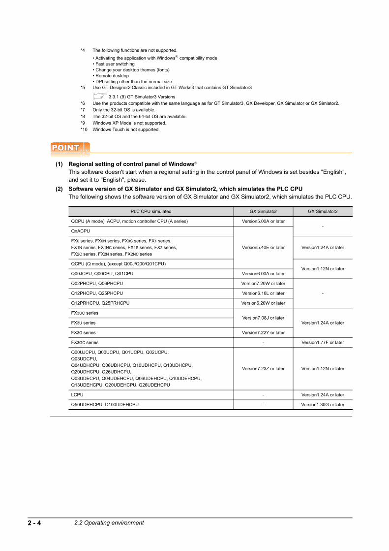
*4 The following functions are not supported.
• Activating the application with Windows compatibility mode• Fast user switching• Change your desktop themes (fonts)• Remote desktop• DPI setting other than the normal size
*5 Use GT Designer2 Classic included in GT Works3 that contains GT Simulator3
3.3.1 (9) GT Simulator3 Versions
*6 Use the products compatible with the same language as for GT Simulator3, GX Developer, GX Simulator or GX Simlator2.
*7 Only the 32-bit OS is available.
*8 The 32-bit OS and the 64-bit OS are available.
*9 Windows XP Mode is not supported.
*10 Windows Touch is not supported.
POINTPOINTPOINT
(1) Regional setting of control panel of Windows
This software doesn't start when a regional setting in the control panel of Windows is set besides "English", and set it to "English", please.
(2) Software version of GX Simulator and GX Simulator2, which simulates the PLC CPUThe following shows the software version of GX Simulator and GX Simulator2, which simulates the PLC CPU.
PLC CPU simulated GX Simulator GX Simulator2
QCPU (A mode), ACPU, motion controller CPU (A series) Version5.00A or later-
QnACPU
Version5.40E or later
FX0 series, FX0N series, FX0S series, FX1 series,
FX1N series, FX1NC series, FX1S series, FX2 series,
FX2C series, FX2N series, FX2NC series
Version1.24A or later
QCPU (Q mode), (except Q00J/Q00/Q01CPU)Version1.12N or later
Q00JCPU, Q00CPU, Q01CPU Version6.00A or later
Q02PHCPU, Q06PHCPU Version7.20W or later
-Q12PHCPU, Q25PHCPU Version6.10L or later
Q12PRHCPU, Q25PRHCPU Version6.20W or later
FX3UC seriesVersion7.08J or later
Version1.24A or laterFX3U series
FX3G series Version7.22Y or later
FX3GC series - Version1.77F or later
Q00UJCPU, Q00UCPU, Q01UCPU, Q02UCPU,
Q03UDCPU,
Q04UDHCPU, Q06UDHCPU, Q10UDHCPU, Q13UDHCPU,
Q20UDHCPU, Q26UDHCPU,
Q03UDECPU, Q04UDEHCPU, Q06UDEHCPU, Q10UDEHCPU,
Q13UDEHCPU, Q20UDEHCPU, Q26UDEHCPU
Version7.23Z or later Version1.12N or later
LCPU - Version1.24A or later
Q50UDEHCPU, Q100UDEHCPU - Version1.30G or later
2 - 4 2.2 Operating environment

1
OV
ER
VIE
W
2
SY
ST
EM
C
ON
FIG
UR
AT
ION
3
SP
EC
IFIC
AT
ION
S
4
SC
RE
EN
C
ON
FIG
UR
AT
ION
OF
G
T S
IMU
LAT
OR
3
5
GT
SIM
ULA
TO
R3
OP
ER
AT
ING
ME
TH
OD
6
FU
NC
TIO
NS
OF
GT
SIM
UL
AT
OR
3
7
DE
VIC
E M
ON
ITO
R
8
TR
OU
BLE
SH
OO
TIN
G
2.3 PLC CPUs that Can Be Simulated
Applicable CPU listThe following table indicates the PLC CPU that can be simulated with GT Simulator3.
(1) MELSEC PLC
*1 Only the PLC CPU area (CPU No.1) is available for simulation.
*2 Monitoring is allowed in the A2SHCPU device range.
*3 Monitoring is allowed in the A3UCPU device range.
Type Model name
QCPUQCPU (Q Mode)
Q00JCPU,
Q02HCPU,
Q02PHCPU,
Q12PRHCPU,
Q00UJCPU,
Q03UDCPU,
Q13UDHCPU,
Q03UDECPU,
Q13UDEHCPU,
Q100UDEHCPU
Q00CPU,
Q06HCPU,
Q06PHCPU,
Q25PRHCPU,
Q00UCPU,
Q04UDHCPU,
Q20UDHCPU,
Q04UDEHCPU,
Q20UDEHCPU,
Q01CPU,
Q12HCPU,
Q12PHCPU,
Q01UCPU,
Q06UDHCPU,
Q26UDHCPU,
Q06UDEHCPU,
Q26UDEHCPU,
Q02CPU,
Q25HCPU,
Q25PHCPU,
Q02UCPU,
Q10UDHCPU,
Q10UDEHCPU,
Q50UDEHCPU,
QCPU (A Mode) Q02CPU-A, Q02HCPU-A, Q06HCPU-A
Network module QJ72LP25-25, QJ72LP25G, QJ72BR15
LCPU L02CPU, L02CPU-P, L26CPU-BT, L26CPU-PBT
QnACPUQnACPU type
Q2ACPU,
Q4ARCPU
Q2ACPU-S1, Q3ACPU, Q4ACPU,
QnASCPU type Q2ASCPU, Q2ASCPU-S1, Q2ASHCPU, Q2ASHCPU-S1
ACPU
AnCPU
type
AnUCPU A2UCPU, A2UCPU-S1, A3UCPU, A4UCPU
AnACPU A2ACPU, A2ACPU-S1, A3ACPU
AnNCPU A1NCPU, A2NCPU, A2NCPU-S1, A3NCPU
AnSCPU
type
AnUS(H)CPU A2USCPU, A2USCPU-S1, A2USHCPU-S1
AnS(H)CPUA1SCPU,
A1SHCPU,
A1SCPU-S1,
A2SHCPU
A1SCPUC24-R2, A2SCPU,
A1SJ(H)CPU A1SJCPU, A1SJCPU-S3, A1SJHCPU
A1FXCPU A1FXCPU
A0J2HCPU, A2CCPU, A2CCPUC24, A2CJCPU
FXCPU
FX0 series,
FX1 series,
FX2 series,
FX3G series,
FX0N series,
FX1N series,
FX2C series,
FX3GC series,
FX0S series,
FX1NC series,
FX2N series,
FX3U series,
FX1S series,
FX2NC series,
FX3UC series
MELSECNET/H remote I/O station QJ72LP25-25, QJ72LP25G, QJ72BR15
CC-Link IE Field Network head module LJ72GF15-T2
Motion controller CPU
Q series Q170MCPU*1
A seriesA171SHCPU*2,
A273UHCPU*3,
A172SHCPU*2,
A273UHCPU-S3*3
A173UHCPU*3, A173UHCPU-S1*3,
2.3 PLC CPUs that Can Be Simulated 2 - 5

(2) OMRON PLC*1
(a) Compatible model
*1 Only direct CPU connection is compatible.
The connection to the RS-232C adaptor, connection cable, rack type host link unit, serial communication module, communication
board or serial communication board is not compatible.
*2 RS-422 communication is not compatible. (RS-232 communication only)
(b) Setting of the PLC CPU side*3
When connecting to GT Simulator3, set for PLC CPU side as follows.
*3 For the setting of the PLC CPU side, refer to the following manual.
• For GOT1000 series
GOT1000 Series Connection Manual (Non-Mitsubishi Products 1) for GT Works3• For GOT-A900 series
GOT-A900 Series User's Manual (GT Works2 Version /GT Designer2 Version compatible Connection System Manual)
Type Model name
PLC CPU
CPM2A
CQM1, CQM1H
CS1, CS1D
CJ1H, CJ1G, CJ1M, CJ2H
C200H series (C200HX, C200HG)
CP1E
CV500*2, CV1000*2, CV2000*2
CVM1-CPU01*2, CVM1-CPU11*2, CVM1-CPU21*2
Item Set value
Transmission speed 9600bps
Data length 7 bits
Stop bit 2 bits
Parity Even
Communicating condition format Individual setting
Host link station No. 00
2 - 6 2.3 PLC CPUs that Can Be Simulated
1
OV
ER
VIE
W
2
SY
ST
EM
C
ON
FIG
UR
AT
ION
3
SP
EC
IFIC
AT
ION
S
4
SC
RE
EN
C
ON
FIG
UR
AT
ION
OF
G
T S
IMU
LAT
OR
3
5
GT
SIM
ULA
TO
R3
OP
ER
AT
ING
ME
TH
OD
6
FU
NC
TIO
NS
OF
GT
SIM
UL
AT
OR
3
7
DE
VIC
E M
ON
ITO
R
8
TR
OU
BLE
SH
OO
TIN
G
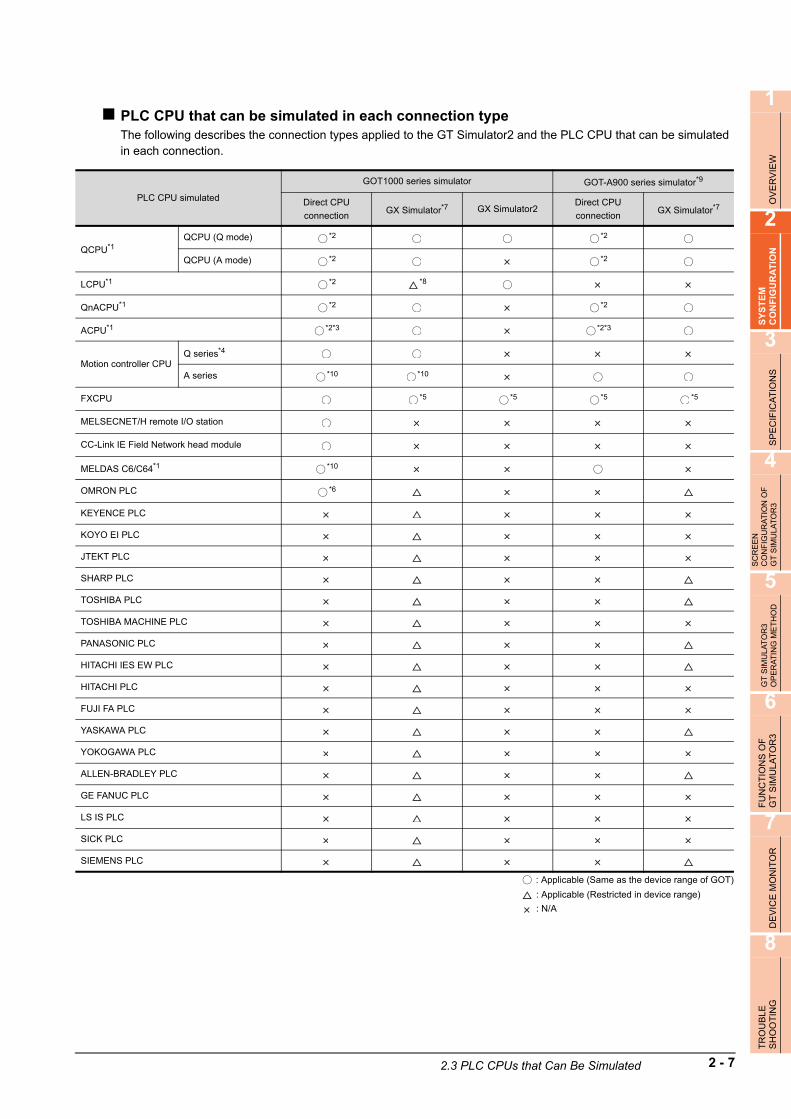
PLC CPU that can be simulated in each connection typeThe following describes the connection types applied to the GT Simulator2 and the PLC CPU that can be simulated in each connection.
: Applicable (Same as the device range of GOT)
: Applicable (Restricted in device range)
: N/A
PLC CPU simulated
GOT1000 series simulator GOT-A900 series simulator*9
Direct CPU
connectionGX Simulator*7 GX Simulator2
Direct CPU
connectionGX Simulator*7
QCPU*1QCPU (Q mode) *2 *2
QCPU (A mode) *2 *2
LCPU*1 *2 *8
QnACPU*1 *2 *2
ACPU*1 *2*3 *2*3
Motion controller CPUQ series*4
A series *10 *10
FXCPU *5 *5 *5 *5
MELSECNET/H remote I/O station
CC-Link IE Field Network head module
MELDAS C6/C64*1 *10
OMRON PLC *6
KEYENCE PLC
KOYO EI PLC
JTEKT PLC
SHARP PLC
TOSHIBA PLC
TOSHIBA MACHINE PLC
PANASONIC PLC
HITACHI IES EW PLC
HITACHI PLC
FUJI FA PLC
YASKAWA PLC
YOKOGAWA PLC
ALLEN-BRADLEY PLC
GE FANUC PLC
LS IS PLC
SICK PLC
SIEMENS PLC
2.3 PLC CPUs that Can Be Simulated 2 - 7
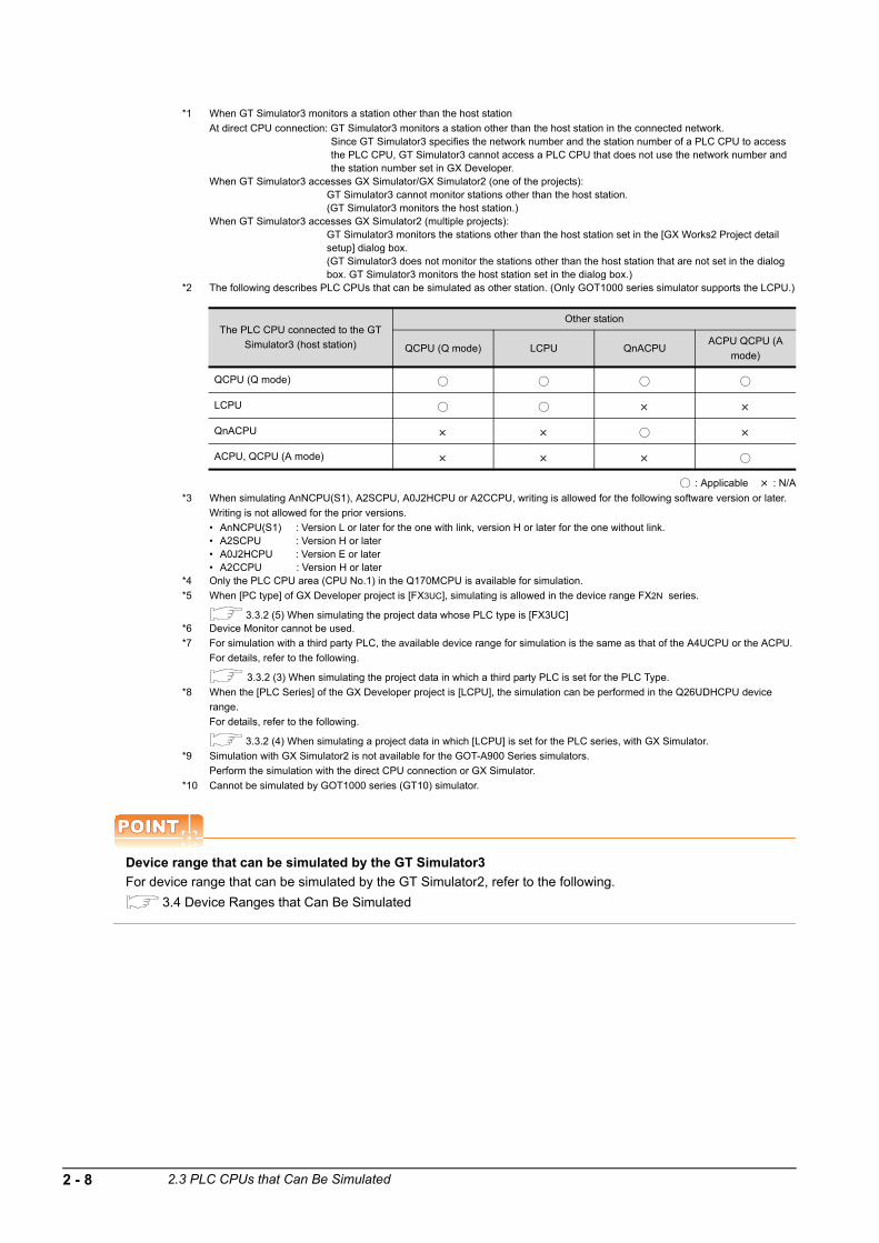
*1 When GT Simulator3 monitors a station other than the host station
At direct CPU connection: GT Simulator3 monitors a station other than the host station in the connected network.Since GT Simulator3 specifies the network number and the station number of a PLC CPU to access the PLC CPU, GT Simulator3 cannot access a PLC CPU that does not use the network number and the station number set in GX Developer.
When GT Simulator3 accesses GX Simulator/GX Simulator2 (one of the projects): GT Simulator3 cannot monitor stations other than the host station. (GT Simulator3 monitors the host station.)
When GT Simulator3 accesses GX Simulator2 (multiple projects): GT Simulator3 monitors the stations other than the host station set in the [GX Works2 Project detail setup] dialog box.(GT Simulator3 does not monitor the stations other than the host station that are not set in the dialog box. GT Simulator3 monitors the host station set in the dialog box.)
*2 The following describes PLC CPUs that can be simulated as other station. (Only GOT1000 series simulator supports the LCPU.)
: Applicable : N/A
*3 When simulating AnNCPU(S1), A2SCPU, A0J2HCPU or A2CCPU, writing is allowed for the following software version or later.
Writing is not allowed for the prior versions.
• AnNCPU(S1) : Version L or later for the one with link, version H or later for the one without link.• A2SCPU : Version H or later• A0J2HCPU : Version E or later• A2CCPU : Version H or later
*4 Only the PLC CPU area (CPU No.1) in the Q170MCPU is available for simulation.
*5 When [PC type] of GX Developer project is [FX3UC], simulating is allowed in the device range FX2N series.
3.3.2 (5) When simulating the project data whose PLC type is [FX3UC]*6 Device Monitor cannot be used.
*7 For simulation with a third party PLC, the available device range for simulation is the same as that of the A4UCPU or the ACPU.
For details, refer to the following.
3.3.2 (3) When simulating the project data in which a third party PLC is set for the PLC Type.
*8 When the [PLC Series] of the GX Developer project is [LCPU], the simulation can be performed in the Q26UDHCPU device
range.
For details, refer to the following.
3.3.2 (4) When simulating a project data in which [LCPU] is set for the PLC series, with GX Simulator.
*9 Simulation with GX Simulator2 is not available for the GOT-A900 Series simulators.
Perform the simulation with the direct CPU connection or GX Simulator.
*10 Cannot be simulated by GOT1000 series (GT10) simulator.
POINTPOINTPOINT
Device range that can be simulated by the GT Simulator3
For device range that can be simulated by the GT Simulator2, refer to the following.
3.4 Device Ranges that Can Be Simulated
The PLC CPU connected to the GT
Simulator3 (host station)
Other station
QCPU (Q mode) LCPU QnACPUACPU QCPU (A
mode)
QCPU (Q mode)
LCPU
QnACPU
ACPU, QCPU (A mode)
2 - 8 2.3 PLC CPUs that Can Be Simulated

1
OV
ER
VIE
W
2
SY
ST
EM
C
ON
FIG
UR
AT
ION
3
SP
EC
IFIC
AT
ION
S
4
SC
RE
EN
C
ON
FIG
UR
AT
ION
OF
G
T S
IMU
LAT
OR
3
5
GT
SIM
ULA
TO
R3
OP
ER
AT
ING
ME
TH
OD
6
FU
NC
TIO
NS
OF
GT
SIM
UL
AT
OR
3
7
DE
VIC
E M
ON
ITO
R
8
TR
OU
BLE
SH
OO
TIN
G
2.4 Connection Cable
This section provides the converter/cable whose operations has been checked by our company.
POINTPOINTPOINT
Converter/Cable used in GT Simulator3
The converter/cable used for the GX Developer can be applied to the GT Simulator3.
2.4.1 Connecting to QCPU or motion controller CPU (Q series)
Using MITSUBISHI product or product manufactured by Mitsubishi Electric System & Service Co., Ltd.
(1) At the connection with the RS-232 cable
(a) For users employing GOT1000 series simulator
(b) For users employing GOT-A900 series simulator
*1 For the motion controller CPU (Q series), only the PLC CPU area (CPU No.1) in the Q170MCPU is available for simulation.
(2) Connection via USB cableFor users employing GOT1000 series simulator• With Universal model QCPU
RS-232 cable*1
Personal computer: D-sub 9-pin Controller: MINI-DIN6-pin
GT01-C30R2-6P (3m)(Mitsubishi Electric System & service Co.,Ltd)
RS-232 cable*1
Personal computer: D-sub 9-pin Controller: MINI-DIN6-pin
QC30R2 (3m)(Mitsubishi Electric)
USB cable
Personal computer: USB TYPE-A Controller: USB Mini-B
MR-J3USBCBL3M (3m)(Mitsubishi Electric)
Personal computer: USB TYPE-A Controller: USB Mini-B
GT09-C30USB-5P (3m)(Mitsubishi Electric System & service Co.,Ltd)
2.4 Connection Cable 2 - 9

Using product manufactured by ELECOM CO., LTD. (Recommended Product)• Connection via USB cable
For users employing GOT1000 series simulator
(a) With Universal model QCPU
(b) With Basic model QCPU, High Performance model QCPU, Process CPU, Redundant CPU
Using product manufactured by BUFFALO KOKUYO SUPPLY INC. (Recommended Product)• Connection via USB cable
For users employing GOT1000 series simulator
(a) With Universal model QCPU
(b) With Basic model QCPU, High Performance model QCPU, Process CPU, Redundant CPU
Using product manufactured by LOAS CO., LTD. (Recommended Product)• Connection via USB cable
For users employing GOT1000 series simulator
• With Universal model QCPU
USB cable/USB conversion adapter
Personal computer: USB TYPE-A Controller: USB Mini-B
USB-M53 (3m)
Personal computer: USB TYPE-A Controller: USB Mini-B
+
USB2-30 (3m) AD-USBBFTM5M
USB cable
Personal computer: USB TYPE-A Controller: USB TYPE-B
USB2-30 (3m)
USB cable/USB conversion adapter
Personal computer: USB TYPE-A Controller: USB Mini-B
+
AU2-30 (3m) AUXUBM5
USB cable
Personal computer: USB TYPE-A Controller: USB TYPE-B
AU2-30 (3m)
USB cable
Personal computer: USB TYPE-A Controller: USB Mini-B
ZUM-430 (3m)
2 - 10 2.4 Connection Cable

1
OV
ER
VIE
W
2
SY
ST
EM
C
ON
FIG
UR
AT
ION
3
SP
EC
IFIC
AT
ION
S
4
SC
RE
EN
C
ON
FIG
UR
AT
ION
OF
G
T S
IMU
LAT
OR
3
5
GT
SIM
ULA
TO
R3
OP
ER
AT
ING
ME
TH
OD
6
FU
NC
TIO
NS
OF
GT
SIM
UL
AT
OR
3
7
DE
VIC
E M
ON
ITO
R
8
TR
OU
BLE
SH
OO
TIN
G
2.4.2 Connecting to LCPU
Using MITSUBISHI product or product manufactured by Mitsubishi Electric System & Service Co., Ltd.
(1) At the connection with the RS-232 cable
*1 The adapter L6ADP-R2 is required for the direct CPU connection.
(2) Connection via USB cable
Using product manufactured by ELECOM CO., LTD. (Recommended Product)
Connection via USB cable
Using product manufactured by LOAS CO., LTD. (Recommended Product)
Connection via USB cable
RS-232 cable*1
Personal computer: D-sub 9-pin Controller: MINI-DIN6-pin
GT01-C30R2-6P (3m)(Mitsubishi Electric System & service Co.,Ltd)
USB cable
Personal computer: USB TYPE-A Controller: USB Mini-B
MR-J3USBCBL3M (3m)(Mitsubishi Electric)
Personal computer: USB TYPE-A Controller: USB Mini-B
GT09-C30USB-5P (3m)(Mitsubishi Electric System & service Co.,Ltd)
USB cable
Personal computer: USB TYPE-A Controller: USB Mini-B
USB-M53 (3m)
USB cable
Personal computer: USB TYPE-A Controller: USB Mini-B
ZUM-430 (3m)
2.4 Connection Cable 2 - 11

2.4.3 Connecting to QnACPU, ACPU, motion controller CPU (A series) and FXCPU
Using MITSUBISHI product or product manufactured by Mitsubishi Electric System & Service Co., Ltd.
(1) At the connection with the RS-232 cable/RS-422 cable
*1 When using a DOS/V PC, a straight cable for conversion between 9-pin D-sub and 25-pin D-sub is required separately.
*2 How to distinguish products compatible with QnACPU, ACPU.
Check the model name label of the cable.
*3 When connecting the FX-232AWC-H to the FX3UC/FX3UCPU, transmission speed of 9600/19200/38400/57600/115200 bps is
available.
When connecting the FX-232AWC or FX-232AW, either of transmission speed of 9600/19200bps is available.
• For users employing GOT1000 series simulatorFor connection to the function extension board or communication special adapter of FX1S/FX1N/FX2N/
FX1NC/FX2NC/FX3G/FX3GC/FX3U/FX3UCCPU, the following cables are available.
PC side (RS-232 cable)RS-232/RS-422
Converter*3PLC CPU Side(RS-422 cable)
RS-232 cable*1*2
F2-232CAB*1*2 (Mitsubishi Electric)(For the 25-pin D-sub connector of the PC side)
FX-232AWC
(Mitsubishi Electric)
FX-232AWC-H
(FX series only)
(Mitsubishi Electric)
FX-232AW
(Mitsubishi Electric)
FX-422CAB(0.3m) (Mitsubishi Electric),
FX-422CAB-150(1.5m) (Mitsubishi Electric)
(For connecting to QnACPU, ACPU, motion controller
CPU (A series), FX1CPU, FX2CPU, or FX2CCPU)
F2-232CAB-1*2 (Mitsubishi Electric)(For the 9-pin D-sub connector of the PC side)
FX-422CAB0(1.5m) (Mitsubishi Electric)
(For connecting to FX0/FX0S/FX0N/FX1S/FX1N/FX2N/
FX1NC/FX2NC/FX3G/FX3GC/FX3U/FX3UCCPU)AC30N2A*1 (Mitsubishi Electric)(For the 25-pin D-sub connector of the PC side)
F2-232CAB
Y990C*****
F2-232CAB-1
Y990C*****
F2-232CAB(F/FX/A)
Y990C*****
F2-232CAB-1(F/FX/A)
Y990C*****
Incompatible products Compatible products (with indication of F/FX/A)
GT01-C30R2-9S (Mitsubishi Electric)
GT01-C30R2-25P (Mitsubishi Electric)
2 - 12 2.4 Connection Cable

1
OV
ER
VIE
W
2
SY
ST
EM
C
ON
FIG
UR
AT
ION
3
SP
EC
IFIC
AT
ION
S
4
SC
RE
EN
C
ON
FIG
UR
AT
ION
OF
G
T S
IMU
LAT
OR
3
5
GT
SIM
ULA
TO
R3
OP
ER
AT
ING
ME
TH
OD
6
FU
NC
TIO
NS
OF
GT
SIM
UL
AT
OR
3
7
DE
VIC
E M
ON
ITO
R
8
TR
OU
BLE
SH
OO
TIN
G
*1 The following system configurations are available in the GT01-C30R2-9S.
*2 The following system configurations are available in the GT01-C30R2-25P.
Model name Function extension board Communication special adapter PC side connector
FX3U series,
FX3UC series
(FX3UC- -LT)
FX3U-232-BD -
9-pin D-subFX3U-232-BD, FX3U-485-BD,
FX3U-422-BD, FX3U-USB-BD,
FX3U-CNV-BD
FX3U-232ADP
FX3UC series
(FX3UC- /D,
FX3UC- /DSS)
- FX3U-232ADP 9-pin D-sub
FX3G seriesFX3G-232-BD -
9-pin D-subFX3G-CNV-BD FX3U-232ADP
FX3GC series - FX3U-232ADP 9-pin D-sub
FX2N seriesFX2N-232-BD -
9-pin D-subFX2N-CNV-BD FX2NC-232ADP
FX1NC,
FX2NC series- FX2NC-232ADP 9-pin D-sub
FX1S, FX1N seriesFX1N-232-BD -
9-pin D-subFX1N-CNV-BD FX2NC-232ADP
Model name Function extension board Communication special adapter PC side connector
FX3U series,
FX3UC series
(FX3UC- -LT)
FX3U-232-BD -
25-pin D-subFX3U-232-BD, FX3U-485-BD,
FX3U-422-BD, FX3U-USB-BD,
FX3U-CNV-BD
FX3U-232ADP
FX3UC series
(FX3UC- /D,
FX3UC- /DSS)
- FX3U-232ADP 25-pin D-sub
FX3G seriesFX3G-232-BD -
25-pin D-subFX3G-CNV-BD FX3U-232ADP
FX3GC series - FX3U-232ADP 25-pin D-sub
FX2N series
FX2N-CNV-BD FX0N-232ADP 9-pin D-sub
FX2N-232-BD -25-pin D-sub
FX2N-CNV-BD FX2NC-232ADP
FX1NC,
FX2NC series
- FX0N-232ADP 9-pin D-sub
- FX2NC-232ADP 25-pin D-sub
FX1S, FX1N series
FX1N-CNV-BD FX0N-232ADP 9-pin D-sub
FX1N-232-BD -25-pin D-sub
FX1N-CNV-BD FX2NC-232ADP
2.4 Connection Cable 2 - 13

(2) Connection via USB cableFor connection to the FX3G or FX3GC series built-in USB port, the following cables are available.
Refer to the following manual for the available cables other than the above.
FX3U SERIES USER'S MANUAL - Hardware Edition
POINTPOINTPOINT
(1) Specifications and precautions for converters/cablesRefer to the following manual for the specifications and precautions for converters/cables.
The manual for each product
(2) Inserting and removing a converter/cable that receives electricity from the 5VDC powerTurn the PLC CPU side power OFF before inserting and removing the converter/cable that receives electricity from the PLC CPU side 5VDC power.
(3) Inserting and removing a converter/cable that does not receive electricity from the 5VDC powerRefer to the following procedures when inserting and removing the peripheral device or cable that does not receive electricity from the PLC CPU side 5VDC power (receives from an external power supply).
1. Make sure to touch the static discharge wrist strap or grounded metal before operation and discharge electrostatic from cables, human body or others.
2. Turn off the PC.
3. Turn off the converter.Ground the FG terminal if provided.
4. Insert and remove the converter/cable connected to the PC and PLC.
5. Turn on the converter.
6. Turn on the PC.
7. Start the software package.
USB cable
Personal computer: USB TYPE-A Controller: USB Mini-B
MR-J3USBCBL3M (3m) (Mitsubishi Electric)
Personal computer: USB TYPE-A Controller: USB Mini-B
GT09-C30USB-5P (3m) (Mitsubishi Electric System & service Co.,Ltd)
2 - 14 2.4 Connection Cable

1
OV
ER
VIE
W
2
SY
ST
EM
C
ON
FIG
UR
AT
ION
3
SP
EC
IFIC
AT
ION
S
4
SC
RE
EN
C
ON
FIG
UR
AT
ION
OF
G
T S
IMU
LAT
OR
3
5
GT
SIM
ULA
TO
R3
OP
ER
AT
ING
ME
TH
OD
6
FU
NC
TIO
NS
OF
GT
SIM
UL
AT
OR
3
7
DE
VIC
E M
ON
ITO
R
8
TR
OU
BLE
SH
OO
TIN
G
2.4.4 Connecting to MELSECNET/H remote I/O station
Using MITSUBISHI product or product manufactured by Mitsubishi Electric System & Service Co., Ltd.At the connection with the RS-232 cable
(1) For users employing GOT1000 series simulator
(2) For users employing GOT-A900 series simulator
2.4.5 Connecting to CC-Link IE Field Network head module
Using MITSUBISHI product or product manufactured by Mitsubishi Electric System & Service Co., Ltd.Connection via USB cable
Using product manufactured by ELECOM CO., LTD. (Recommended Product)Connection via USB cable
Using product manufactured by LOAS CO., LTD. (Recommended Product)Connection via USB cable
RS-232 cable*1
Personal computer: D-sub 9-pin Controller: MINI-DIN6-pin
GT01-C30R2-6P (3m) (Mitsubishi Electric System & service Co.,Ltd)
RS-232 cable
Personal computer: D-sub 9-pin Controller: MINI-DIN6-pin
QC30R2 (3m) (Mitsubishi Electric)
USB cable
Personal computer: USB TYPE-A Controller: USB Mini-B
MR-J3USBCBL3M (3m) (Mitsubishi Electric)
Personal computer: USB TYPE-A Controller: USB Mini-B
GT09-C30USB-5P (3m) (Mitsubishi Electric System & service Co.,Ltd)
USB cable
Personal computer: USB TYPE-A Controller: USB Mini-B
USB-M53 (3m)
USB cable
Personal computer: USB A TYPE-A Controller: USB Mini-B
ZUM-430 (3m)
2.4 Connection Cable 2 - 15

2.4.6 Connecting to MELDAS C6/C64
The conversion cable for connecting the GT Simulator3 and MELDAS C6/C64 is required to be created by the user.The following describes the connection diagram, connector and others for each cable.
Connection diagram
Connector specifications
(1) PC side connectorUse the connector compatible with the PC side.
(2) MELDAS C6/C64 side connectorUse the connector compatible with MELDAS C6/C64 side.For details, refer to the following manual.
User's Manual for the MELDAS C6/C64
Precautions for creating cablesThe length of the conversion cable must be 15m or shorter.
Personal Computer(GT
Simulator2) Side Cable Connection and Signal Direction
MELDAS C6/C64(TERMINAL)
Side
Signal name Pin number Signal name
GND 1 GND
RD(RXD) -
SD(TXD) -
GND -
DR(DSR) 6 SD(TXD)
CS(CTS) -
11 GND
16 RD(RXD)
18 ER(DTR)
2 - 16 2.4 Connection Cable

1
OV
ER
VIE
W
2
SY
ST
EM
C
ON
FIG
UR
AT
ION
3
SP
EC
IFIC
AT
ION
S
4
SC
RE
EN
C
ON
FIG
UR
AT
ION
OF
G
T S
IMU
LAT
OR
3
5
GT
SIM
ULA
TO
R3
OP
ER
AT
ING
ME
TH
OD
6
FU
NC
TIO
NS
OF
GT
SIM
UL
AT
OR
3
7
DE
VIC
E M
ON
ITO
R
8
TR
OU
BLE
SH
OO
TIN
G
2.4.7 Connecting to Omron PLC CPU
When using a product made in Mitsubishi Electric System Service Co., Ltd.
When using an RS-232 cable prepared by userThe following describes the connection diagram, connector and others for each cable.
(1) Connection diagram
(2) Connector specifications
(a) PC side connectorUse the connector compatible with the PC side.
(b) Omron PLC CPU side connectorUse the connector compatible with Omron PLC CPU side.For details, refer to the following manual.
User's Manual for Omron PLC CPU
(3) Precautions for creating cablesThe length of the cable must be 15m or less.
RS-232 cable
PC (GT Simulator2) sideCable connection and signal direction
Omron products side
Signal name Pin No. Signal name
CD 1 FG
RD(RXD) 2 SD
SD(TXD) 3 RD
ER(DTR) 4 RS
SG 5 CS
DR(DSR) 6 -
RS(RTS) 7 FR
CS(CTS) 8 ER
- 9 SG
GT09-C30R20101-9P(For the 9-pin D-sub connector of the PC side)
2.4 Connection Cable 2 - 17

2 - 18 2.4 Connection Cable

1
OV
ER
VIE
W
2
SY
ST
EM
C
ON
FIG
UR
AT
ION
3
SP
EC
IFIC
AT
ION
S
4
SC
RE
EN
C
ON
FIG
UR
AT
ION
OF
G
T S
IMU
LAT
OR
3
5
GT
SIM
ULA
TO
R3
OP
ER
AT
ING
ME
TH
OD
6
FU
NC
TIO
NS
OF
G
T S
IMU
LA
TO
R3
7
DE
VIC
E M
ON
ITO
R
8
TR
OU
BLE
SH
OO
TIN
G
3. SPECIFICATIONS
3.1 GOT that Can Be Simulated
The following table indicates the GOT that can be simulated on GT Simulator3.Any GOT other than the below cannot be simulated.
For GOT1000 series (GT16) simulator
For GOT1000 series (GT15) simulator
For GOT1000 series (GT14) simulator
For GOT1000 series (GT12) simulator
For GOT1000 series (GT11) simulator
For GOT1000 series (GT10) simulator
Name Resolution (dots) Display color Memory capacity *1
GT16**-X 1024 768
High Color (16-bits) 57M bytesGT16**-S 800 600
GT16**-V*2
640 480GT165*-V
Name Resolution (dots) Display color Memory capacity *1
GT15**-X 1024 768
High Color (16-bits) 57M bytes
GT15**-S 800 600
GT15**-V*3
640 480GT155*-V
GT15**-Q 320 240
Name Resolution (dots) Display color Memory capacity *1
GT14**-Q 320 240 High Color (16-bits) 9M bytes
Name Resolution (dots) Display color Memory capacity *1
GT12**-V 640 480 256 colors 3M bytes
Name Resolution (dots) Display color Memory capacity *1
GT11**-Q *4 320 240 256 colors 3M bytes
Name Resolution (dots) Display color Memory capacity *1
GT10**-Q 320 240 256 colors
3M bytesGT1030 288 96Monochrome
GT1020 160 64
3.1 GOT that Can Be Simulated 3 - 1

For GOT-A900 series simulator
*1 The memory of GOT user area to store project data and Option OS, etc.
*2 Incompatible with the grip switch, the operation switch, and the emergency stop switch of the GT16 Handy GOT.
*3 When simulating GT15**-VN, select the GT15**-V.
*4 Incompatible with the grip switch, the operation switch, and the emergency stop switch of the GT11 Handy GOT.
*5 Incompatible with the grip switch, the operation switch, and the emergency stop switch of the A950 Handy GOT.
POINTPOINTPOINT
Display color
The number of display colors for the actual GOT and for GT Simulator3 may differ according to the model.Check the actual display colors for the GOT with [Preview] on GT Designer3.
Name Resolution (dots) Display color Memory capacity *1
GT SoftGOT2
1280 1024
256 colors
33M bytes1024 768
800 600
640 480
A985GOT 800 600
9M bytesA97*GOT 640 480
A960GOT 640 480
A956WGOT 480 234
A95*GOT*5 320 240 3M bytes
3 - 2 3.1 GOT that Can Be Simulated
1
OV
ER
VIE
W
2
SY
ST
EM
C
ON
FIG
UR
AT
ION
3
SP
EC
IFIC
AT
ION
S
4
SC
RE
EN
C
ON
FIG
UR
AT
ION
OF
G
T S
IMU
LAT
OR
3
5
GT
SIM
ULA
TO
R3
OP
ER
AT
ING
ME
TH
OD
6
FU
NC
TIO
NS
OF
G
T S
IMU
LA
TO
R3
7
DE
VIC
E M
ON
ITO
R
8
TR
OU
BLE
SH
OO
TIN
G
3.2 Functions that cannot be simulated
The following functions cannot be used on GT Simulator3.
For GOT1000 series (GT16) simulator
*1 Refer to the following manual for details of Utility function.
GT16 User's Manual (Basic Utility)
*2 Refer to the following manual for details of Extension and Option functions.
GOT1000 Series User's Manual (Extended Functions, Option Functions) for GT Works3
*3 Video windows are displayed in blue color. (Video images are not displayed.)
A window to which transparent processing is applied or a window displayed on an overlap window is not displayed.
The resolution of video windows cannot be changed. (Fixed to 640 480 dots)
*4 The equivalent function is available when using the GT Simulator3 and GX Developer on the same PC.
Function category Function name
Utility functions*1
GOT setup
GOT main unit
setup
Time setting, Transparent mode,
Clean, Video/RGB setting ,
Multimedia setting
DisplayScreen save time, Screen save backlight,
Battery alarm display, Brightness,contrast
OperationKey sensitivity, Key reaction speed,
Touch panel calibration, Touch detection mode
GOT
maintenance
function
Maintenance timing setting, Addtion times reset,
GOT start time, Behavior of duplicate IPs
Communication setting Communication setting
Debug Debug
Self check Self check
Data control
Data control Data control
OS/project
informationOS/project information
Extension function*2
System monitor function, Barcode function,
Video display function*3, RGB display function,
Multimedia function, External I/O function,
Operation panel function, Backup/restore function,
CNC data I/O function, RFID function
Operator authentication (External
authentication/fingerprint authentication)
function,
Remote personal computer operation,
USB mouse/keyboard function, MELSEC-L troubleshooting function,
SoftGOT-GOT link function, Log viewer function,
Motion program (SV43) edit, Motion program (SV43) I/O,
VNC® server function
Option functions*2
Ladder monitor function*4, List editor for MELSEC-A*4,
List editor for MELSEC-FX*4, Intelligent module monitor function,
Network monitor function, Q motion monitor function,
Servo amplifier monitor function, CNC monitor function,
Gateway function, MES interface function,
SFC monitor function, Ladder editor function,
Motion SFC monitor function
OthersFA transparent functions, Human sensor function,
RGB output function
3.2 Functions that cannot be simulated 3 - 3

POINTPOINTPOINT
[GOT Setup] of Utility function
The GT Simulator3 can set up [GOT setup], but some functions are inoperative.The following table indicates whether they are operative or not on GT Simulator3.
: Operable : Inoperable
*1 When using the following basic software, there is no differentiation in [LONG] and [SHORT] of Buzzer Volume.
The same length of Buzzer Volume sounds.
Item Operability on GT Simulator3
Display
Language
Opening screen time
Screen save time
Screen save backlight
Battery alarm display
Brightness, contrast
Operation
Buzzer volume
Window move buzzer
Security setting
Utility call key *1
Key sensitivity
Key reaction speed
Touch panel calibration
Touch Detection Mode
Transparent mode settings
3 - 4 3.2 Functions that cannot be simulated
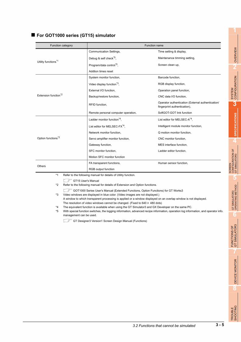
1
OV
ER
VIE
W
2
SY
ST
EM
C
ON
FIG
UR
AT
ION
3
SP
EC
IFIC
AT
ION
S
4
SC
RE
EN
C
ON
FIG
UR
AT
ION
OF
G
T S
IMU
LAT
OR
3
5
GT
SIM
ULA
TO
R3
OP
ER
AT
ING
ME
TH
OD
6
FU
NC
TIO
NS
OF
G
T S
IMU
LA
TO
R3
7
DE
VIC
E M
ON
ITO
R
8
TR
OU
BLE
SH
OO
TIN
G
For GOT1000 series (GT15) simulator
*1 Refer to the following manual for details of Utility function.
GT15 User's Manual
*2 Refer to the following manual for details of Extension and Option functions.
GOT1000 Series User's Manual (Extended Functions, Option Functions) for GT Works3
*3 Video windows are displayed in blue color. (Video images are not displayed.)
A window to which transparent processing is applied or a window displayed on an overlap window is not displayed.
The resolution of video windows cannot be changed. (Fixed to 640 480 dots)
*4 The equivalent function is available when using the GT Simulator3 and GX Developer on the same PC.
*5 With special function switches, the logging information, advanced recipe information, operation log information, and operator info.
management can be used.
GT Designer3 Version1 Screen Design Manual (Functions)
Function category Function name
Utility functions*1
Communication Settings, Time setting & display,
Debug & self check*5, Maintenance timming setting,
Program/data control*5, Screen clean up,
Addtion times reset
Extension function*2
System monitor function, Barcode function,
Video display function*3, RGB display function,
External I/O function, Operation panel function,
Backup/restore function, CNC data I/O function,
RFID function, Operator authentication (External authentication/
fingerprint authentication),
Remote personal computer operation, SoftGOT-GOT link function
Option functions*2
Ladder monitor function*4, List editor for MELSEC-A*4,
List editor for MELSEC-FX*4, Intelligent module monitor function,
Network monitor function, Q motion monitor function,
Servo amplifier monitor function, CNC monitor function,
Gateway function, MES interface function,
SFC monitor function, Ladder editor function,
Motion SFC monitor function
OthersFA transparent functions, Human sensor function,
RGB output function
3.2 Functions that cannot be simulated 3 - 5

POINTPOINTPOINT
[GOT Setup] of Utility function
The GT Simulator3 can set up [GOT setup], but some functions are inoperative.The following table indicates whether they are operative or not on GT Simulator3.
: Operable : Inoperable
*1 When two points are set for the utility call key, click either one point, and then the utility screen is displayed.
Even though [Pressing time] is set, the function does not operate.
*2 Setting item only for GT15**-X
*3 Setting item only for GT15**-S
Item Operability on GT Simulator3
Display
Language
Opening screen time
Screen save time
Screen save backlight
Battery alarm display
Brightness, contrast
Operation
Buzzer volume
Window move buzzer
Security setting
Utility call key *1
Key sensitivity
Key reaction speed
Touch panel calibration*2
Touch Detection Mode
Q/QnA ladder monitor
Transparent mode settings
Video/RGB Setting*3
Backup/restoration setting
3 - 6 3.2 Functions that cannot be simulated

1
OV
ER
VIE
W
2
SY
ST
EM
C
ON
FIG
UR
AT
ION
3
SP
EC
IFIC
AT
ION
S
4
SC
RE
EN
C
ON
FIG
UR
AT
ION
OF
G
T S
IMU
LAT
OR
3
5
GT
SIM
ULA
TO
R3
OP
ER
AT
ING
ME
TH
OD
6
FU
NC
TIO
NS
OF
G
T S
IMU
LA
TO
R3
7
DE
VIC
E M
ON
ITO
R
8
TR
OU
BLE
SH
OO
TIN
G
For GOT1000 series (GT14) simulator
*1 Refer to the following manual for details of Utility function.
GT14 User's Manual
*2 Refer to the following manual for details of Extension and Option functions.
GOT1000 Series User's Manual (Extended Functions, Option Functions) for GT Works3
*3 The equivalent function is available when using the GT Simulator3 and GX Developer on the same PC.
*4 With special function switches, the logging information, advanced recipe information, operation log information, and operator info.
management can be used.
GT Designer3 Version1 Screen Design Manual (Functions)
POINTPOINTPOINT
[GOT Setup] of Utility function
The GT Simulator3 can set up [GOT setup], but some functions are inoperative.The following table indicates whether they are operative or not on GT Simulator3.
: Operable : Inoperable
*1 [Pressing time] is set, the function does not operate.
Function category Function name
Utility functions*1
Communication Settings, Time setting & display,
Debug & self check, Program/data control*4,
Screen clean up
Extension function*2
System monitor function, Barcode function,
Backup/restore function, RFID function,
Operator authentication (External authentication)
function
Option functions*2List editor for MELSEC-A*3, List editor for MELSEC-FX*3,
Gateway function
Others FA transparent functions,
Item Operability on GT Simulator3
Display
Language
Opening screen time
Screen save time
Screen save backlight
Brightness, contrast
Operation
Buzzer volume
Window move buzzer
Security setting
Utility call key *1
Key sensitivity
Key reaction speed
Touch panel calibration*2
Transparent mode settings
Backup/restoration setting
3.2 Functions that cannot be simulated 3 - 7

For GOT1000 series (GT12) simulator
*1 Refer to the following manual for details of Utility function.
GT12 User's Manual
*2 Refer to the following manual for details of Extension and Option functions.
GOT1000 Series User's Manual (Extended Functions, Option Functions) for GT Works3
*3 The equivalent function is available when using the GT Simulator3 and GX Developer on the same PC.
POINTPOINTPOINT
[GOT Setup] of Utility function
The GT Simulator3 can set up [GOT setup], but some functions are inoperative.The following table indicates whether they are operative or not on the GT Simulator3.
: Operable : Inoperable
*1 When two points are set for the utility call key, click either one point, and then the utility screen is displayed.
Even though [Pressing time] is set, the function does not operate.
Function category Function name
Utility functions*1
Communication Settings, Time setting & display,
Program/data control, Debug & self check,
Screen clean up
Extension function*2System monitor function, Barcode function,
RFID function
Option functions*2 List editor for MELSEC-A*3, List editor for MELSEC-FX*3
Others FA transparent functions
Item Operability on GT Simulator3
Display
Language
Opening screen time
Screen save time
Screen save backlight
Battery alarm display
Brightness, contrast
Operation
Buzzer volume
Window move buzzer
Security setting
Utility call key *1
Key sensitivity
Key reaction speed
Handy GOT Grip Switch LED settings
3 - 8 3.2 Functions that cannot be simulated

1
OV
ER
VIE
W
2
SY
ST
EM
C
ON
FIG
UR
AT
ION
3
SP
EC
IFIC
AT
ION
S
4
SC
RE
EN
C
ON
FIG
UR
AT
ION
OF
G
T S
IMU
LAT
OR
3
5
GT
SIM
ULA
TO
R3
OP
ER
AT
ING
ME
TH
OD
6
FU
NC
TIO
NS
OF
G
T S
IMU
LA
TO
R3
7
DE
VIC
E M
ON
ITO
R
8
TR
OU
BLE
SH
OO
TIN
G
For GOT1000 series (GT11) simulator
*1 Refer to the following manual for details of Utility function.
GT11 User's Manual
*2 Refer to the following manual for details of Extension and Option functions.
GOT1000 Series User's Manual (Extended Functions, Option Functions) for GT Works3
*3 The equivalent function is available when using the GT Simulator3 and GX Developer on the same PC.
POINTPOINTPOINT
[GOT Setup] of Utility function
The GT Simulator3 can set up [GOT setup], but some functions are inoperative.The following table indicates whether they are operative or not on the GT Simulator3.
: Operable : Inoperable
*1 When two points are set for the utility call key, click either one point, and then the utility screen is displayed.
Even though [Pressing time] is set, the function does not operate.
Function category Function name
Utility functions*1
Communication Settings, Time setting & display,
Program/data control, Debug & self check,
Screen clean up
Extension function*2System monitor function, Barcode function,
RFID function
Option functions*2 List editor for MELSEC-A*3, List editor for MELSEC-FX*3
Others FA transparent functions
Item Operability on GT Simulator3
Display
Language
Opening screen time
Screen save time
Screen save backlight
Battery alarm display
Brightness, contrast
Operation
Buzzer volume
Window move buzzer
Security setting
Utility call key *1
Key sensitivity
Key reaction speed
Handy GOT Grip Switch LED settings
3.2 Functions that cannot be simulated 3 - 9

For GOT1000 series (GT10) simulator
*1 Refer to the following manual for details of Utility function.
GT10 User's Manual
*2 Refer to the following manual for details of Option functions.
GOT1000 Series User's Manual (Extended Functions, Option Functions) for GT Works3
*3 The equivalent function is available when using the GT Simulator3 and GX Developer on the same PC.
POINTPOINTPOINT
[GOT Setup] of Utility function
The GT Simulator3 can set up [GOT setup], but some functions are inoperative.The following table indicates whether they are operative or not on the GT Simulator3.
: Operable : Inoperable
*1 When two points are set for the utility call key, click either one point, and then the utility screen is displayed.
Even though [Pressing time] is set, the function does not operate.
Function category Function name
Utility functions*1
Communication Settings, Time setting & display,
Data control, Debug,
Screen clean up
Extension function Device monitor function, Barcode function
Option functions*2 List editor for MELSEC-A*3, List editor for MELSEC-FX*3
Others FA transparent functions
Item Operability on GT Simulator3
Display
Screen save
Brightness, contrast
Opening time
Operation
Buzzer setting
Calibration
Key reaction
Clock setting
Security
Utility call *1
3 - 10 3.2 Functions that cannot be simulated

1
OV
ER
VIE
W
2
SY
ST
EM
C
ON
FIG
UR
AT
ION
3
SP
EC
IFIC
AT
ION
S
4
SC
RE
EN
C
ON
FIG
UR
AT
ION
OF
G
T S
IMU
LAT
OR
3
5
GT
SIM
ULA
TO
R3
OP
ER
AT
ING
ME
TH
OD
6
FU
NC
TIO
NS
OF
G
T S
IMU
LA
TO
R3
7
DE
VIC
E M
ON
ITO
R
8
TR
OU
BLE
SH
OO
TIN
G
For GOT-A900 series simulator
*1 Refer to the following manual for details of object function.
GT Designer2 Version Reference Manual
*2 Refer to the following manual for details of Extension and Option functions.
GOT-A900 Series Operating Manual
(GT Works2 Version /GT Designer2 Version compatible Extended • Option Functions Manual)
*3 This function can be used when simulating GT SoftGOT2.
The data is stored into each folder in the GSS2 created in the installation destination folder.
[Rev./Norm], [Writing Notification Device], and [Writing Error Notification Device] of the hard copy function cannot be simulated.
The system information related to the hard copy function also cannot be simulated.
*4 By using the GT Simulator3 snapshot and printing functions equivalent functions become possible.
• 6.1 Snap Shot• 6.2 Print
*5 By using GT Simulator3 and GX Developer together on the personal computer, equivalent functions become possible.
*6 Video windows are displayed in blue color. (Video images are not displayed.)
A window to which transparent processing is applied or a window displayed on an overlap window is not displayed.The RGB screen cannot be displayed.
Function category Function name
Object function*1Report function*3, Hard copy function*3*4,
Test function, Barcode function
Utility function
System monitor, Network monitor,
List edit, Ladder monitor,
Motion/CNC monitor, Special module monitor,
Servo amplifier monitor, Memory information,
Screen & OS copy, Clock,
Screen cleanup, Self-test,
Brightness/contrast adjustment
Extension function*2System monitor function, External I/O function,
Operation Panel function
Option function*2
Ladder monitor function*5, Special unit monitor function,
List editor function*5, Network monitor function*5,
Motion monitor function, Servo amplifier monitor function,
CNC monitor function
Other function
Transparent function, Human sensor function,
Brightness adjustment function, Sound function,
VIDEO/RBG display function*6, Gateway function,
Font change function, System dialog language switching function
3.2 Functions that cannot be simulated 3 - 11

POINTPOINTPOINT
(1) [Main Menu] display of Utility functionThe 2-point press is not allowed for [Menu call key].To display [Main Menu], make [Special Function Switch (Utility)] setting.Refer to the following manual for the setting method.
GT Designer2 Version Reference Manual
(2) [GOT Setup] of Utility functionThe GT Simulator3 can set up [GOT setup], but some functions are inoperative.The following table indicates whether they are operative or not on GT Simulator3.
: Operable : Inoperable
Item Operability on GT Simulator3
Buzzer volume
Outside speaker
Screen save time
Screen save light
Language
3 - 12 3.2 Functions that cannot be simulated

1
OV
ER
VIE
W
2
SY
ST
EM
C
ON
FIG
UR
AT
ION
3
SP
EC
IFIC
AT
ION
S
4
SC
RE
EN
C
ON
FIG
UR
AT
ION
OF
G
T S
IMU
LAT
OR
3
5
GT
SIM
ULA
TO
R3
OP
ER
AT
ING
ME
TH
OD
6
FU
NC
TIO
NS
OF
G
T S
IMU
LA
TO
R3
7
DE
VIC
E M
ON
ITO
R
8
TR
OU
BLE
SH
OO
TIN
G
3.3 Precautions
3.3.1 Precautions for using the GT Simulator3
(1) In the case of simulating project data of GOT-F900 seriesWhen simulating project data of GOT-F900 seriesThe simulation is disabled by changing the [GOT Type] of GT Designer2 to "GOT-A900 series".However, any incompatible functions with the GOT-A900 series cannot be converted.When changing [GOT Type], always back up the data.The functions may not be converted properly when the incompatible functions may not be converted at [GOT Type] changing and [GOT Type] is changed to "GOT-F900 series" again.
(2) Simulating the project data of vertical display typeFor GT11, the project data of vertical display type cannot be simulated while display type can be selected.Perform the simulation after changing [GOT type] of the GT Designer3 to "GT16/GT15".Note that a function that is not compatible with GT16/GT15 cannot be converted.When changing [GOT type], be sure to backup data.If this is not done, the incompatible functions are not be converted when [GOT type] is changed, and these functions cannot be converted correctly when [GOT type] is changed to GT11 again.
(3) The display of the GT Simulator3 and GOTThe display of GT Simulator3 may differ from that of the GOT. Confirm on the GOT for display of the actual GOT.
(4) Numerical DisplayWhen the [View Format] of [Numerical Display] is set to [Real] and if illegal value is stored, illegal value will be displayed on GT Simulator3. (GOT displays [non].)
(5) Time displayThe clock data of the personal computer is used for clock display when simulating GT Simulator3.(GOT reads and shows the clock data of the PLC CPU.)GT Simulator3 does not support the daylight saving function. Do not check [Automatically adjust clock for daylight saving changes] on the personal computer.
(6) Hard copy function[Rev./Norm], [Writing Notification Device], and [Writing Error Notification Device] of the hard copy function cannot be simulated.The system information related to the hard copy function also cannot be simulated.
(7) Logging, advanced recipe, operation log, operator authenticationThe logging information, advanced recipe information, operation log information, and operator info. management cannot be displayed with the utility.For using the logging information, advanced recipe information, operation log information, and operator info. management, set special function switches.For special function switches, refer to the following manual.
GT Designer3 Version1 Screen Design Manual (Fundamentals)
3.3 Precautions 3 - 13

(8) Functions in which data are stored to the memory cardWhen the memory card is set as the file storage destination with objects or option functions, the files will be stored in the hard disc of the PC.The files of each function are stored in the folder listed below.
(a) For GOT1000 series (GT16) simulator
*1 The work folder varies according to the OS of the personal computer in which GT Simulator3 is installed.
The following shows the work folder of each OS.
• Windows 7: Users\(User name)\AppData\Local\MITSUBISHI\GSS3• Windows Vista: Users\(User name)\AppData\Local\MITSUBISHI\GSS3• Windows XP: Document and Settings\(User name)\Local Settings\Application Data\MITSUBISHI\GSS3• Windows 2000: Document and Settings\(User name)\Local Settings\Application Data\MITSUBISHI\GSS3
(Work folder) *1
GT1600
DriveA
Folder name setting with GT Designer3
G1GssUsr
The files shown left are stored to the"G1 GssUsr" folder irrespective of boththe folder and file names set with GT Designer3.
Storage folder of each function files
Print image of hard copyHARDCOPY(.BMP)
Print image of report[REP+serial number.CSV] files Example) REP00001(.CSV) REP00002(.CSV)
B
A folder is created in each drive.
A folder for GT16 is created.
Folder name setting with GT Designer3
G1GssUsr
The files shown left are stored to the"G1 GssUsr" folder irrespective of boththe folder and file names set with GT Designer3.
Storage folder of each function files
Print image of hard copyHARDCOPY(.BMP)
Print image of report[REP+serial number.CSV] files Example) REP00001(.CSV) REP00002(.CSV)
A: Standard CF card
B: Extended Memory card
3 - 14 3.3 Precautions

1
OV
ER
VIE
W
2
SY
ST
EM
C
ON
FIG
UR
AT
ION
3
SP
EC
IFIC
AT
ION
S
4
SC
RE
EN
C
ON
FIG
UR
AT
ION
OF
G
T S
IMU
LAT
OR
3
5
GT
SIM
ULA
TO
R3
OP
ER
AT
ING
ME
TH
OD
6
FU
NC
TIO
NS
OF
G
T S
IMU
LA
TO
R3
7
DE
VIC
E M
ON
ITO
R
8
TR
OU
BLE
SH
OO
TIN
G
(b) For GOT1000 series (GT15) simulator
*1 The work folder varies according to the OS of the personal computer in which GT Simulator3 is installed.
The following shows the work folder of each OS.
• Windows 7: Users\(User name)\AppData\Local\MITSUBISHI\GSS3• Windows Vista: Users\(User name)\AppData\Local\MITSUBISHI\GSS3• Windows XP: Document and Settings\(User name)\Local Settings\Application Data\MITSUBISHI\GSS3• Windows 2000: Document and Settings\(User name)\Local Settings\Application Data\MITSUBISHI\GSS3
(Work folder) *1
GT1500
DriveA
Folder name setting with GT Designer3
G1GssUsr
The files shown left are stored to the"G1 GssUsr" folder irrespective of boththe folder and file names set with GT Designer3.
Storage folder of each function files
Print image of hard copyHARDCOPY(.BMP)
Print image of report[REP+serial number.CSV] files Example) REP00001(.CSV) REP00002(.CSV)
B
A folder is created in each drive.
A folder for GT15 is created.
Folder name setting with GT Designer3
G1GssUsr
The files shown left are stored to the"G1 GssUsr" folder irrespective of boththe folder and file names set with GT Designer3.
Storage folder of each function files
Print image of hard copyHARDCOPY(.BMP)
Print image of report[REP+serial number.CSV] files Example) REP00001(.CSV) REP00002(.CSV)
A: Standard CF Card
B: Extended Memory Card
3.3 Precautions 3 - 15

(c) For GOT1000 series (GT14) simulator
*1 The work folder varies according to the OS of the personal computer in which GT Simulator3 is installed.
The following shows the work folder of each OS.
• Windows 7: Users\(User name)\AppData\Local\MITSUBISHI\GSS3• Windows Vista: Users\(User name)\AppData\Local\MITSUBISHI\GSS3• Windows XP: Document and Settings\(User name)\Local Settings\Application Data\MITSUBISHI\GSS3• Windows 2000: Document and Settings\(User name)\Local Settings\Application Data\MITSUBISHI\GSS3
(d) For GOT1000 series (GT12) simulator
*1 The work folder varies according to the OS of the personal computer in which GT Simulator3 is installed.
The following shows the work folder of each OS.
• Windows 7: Users\(User name)\AppData\Local\MITSUBISHI\GSS3• Windows Vista: Users\(User name)\AppData\Local\MITSUBISHI\GSS3• Windows XP: Document and Settings\(User name)\Local Settings\Application Data\MITSUBISHI\GSS3• Windows 2000: Document and Settings\(User name)\Local Settings\Application Data\MITSUBISHI\GSS3
(e) For GOT1000 series (GT11) simulator
*1 The work folder varies according to the OS of the personal computer in which GT Simulator3 is installed.
The following shows the work folder of each OS.
• Windows 7: Users\(User name)\AppData\Local\MITSUBISHI\GSS3• Windows Vista: Users\(User name)\AppData\Local\MITSUBISHI\GSS3• Windows XP: Document and Settings\(User name)\Local Settings\Application Data\MITSUBISHI\GSS3• Windows 2000: Document and Settings\(User name)\Local Settings\Application Data\MITSUBISHI\GSS3
(Work folder) *1
GT1400
DriveA
Folder name setting with GT Designer3Storage folder of each function files
D
A folder is created in each drive.
A folder for GT14 is created.
Folder name setting with GT Designer3Storage folder of each function files
(Work folder) *1
GT1200
Drive
A
Folder name setting with GT Designer3 (Storage folder of each function files)
D
Folder name setting with GT Designer3 (Storage folder of each function files)
(Work folder) *1
GT1100
Drive
A
Folder name setting with GT Designer3 (Storage folder of each function files)
D
Folder name setting with GT Designer3 (Storage folder of each function files)
3 - 16 3.3 Precautions

1
OV
ER
VIE
W
2
SY
ST
EM
C
ON
FIG
UR
AT
ION
3
SP
EC
IFIC
AT
ION
S
4
SC
RE
EN
C
ON
FIG
UR
AT
ION
OF
G
T S
IMU
LAT
OR
3
5
GT
SIM
ULA
TO
R3
OP
ER
AT
ING
ME
TH
OD
6
FU
NC
TIO
NS
OF
G
T S
IMU
LA
TO
R3
7
DE
VIC
E M
ON
ITO
R
8
TR
OU
BLE
SH
OO
TIN
G
(f) For GOT1000 series (GT10) simulator
*1 The work folder varies according to the OS of the personal computer in which GT Simulator3 is installed.
The following shows the work folder of each OS.
• Windows 7: Users\(User name)\AppData\Local\MITSUBISHI\GSS3• Windows Vista: Users\(User name)\AppData\Local\MITSUBISHI\GSS3• Windows XP: Document and Settings\(User name)\Local Settings\Application Data\MITSUBISHI\GSS3• Windows 2000: Document and Settings\(User name)\Local Settings\Application Data\MITSUBISHI\GSS3
(g) For GOT-A900 series simulator
The storage location differs according to the setting of [GOT type] in [Simulate] on the Action setup tab of [Option].
(9) GT Simulator3 VersionsUse the same version of GT Simulator3 as that of GT Designer3 that the project data is created.When the different version is used, the file may not be opened, the functions and settings may be invalid, or GT Simulator3 does not operate correctly.
Appendix1 Applicable Project Data
(10) Using the project data of GT Designer of the SW3D5C-GOTR-PACK or earlier or those converted by GT Converter
To use the project data of GT Designer2 of the SW3D5C-GOTR-PACK or earlier or those converted by GT Converter, read out and save the project data on the GT Designer of the SW3D5C-GOTR-PACK or later or the GT Designer2.If using the project data of GT Designer of the SW3D5C-GOTR-PACK or earlier or those converted by GT Converter as it is, the GT Simulator2 may not operate normally.
(Work folder) *1
GT1000
Drive
D
Folder name setting with GT Designer3 (Storage folder of each function files)
C:\Document and Settings\(user name)\Local Settings\Application Data\MITSUBISHI\
GTD3
GSS3 (Install folder)
Memcard Data of alarm history display function
and recipe function.
Alarmhst
Hardcopy
Recipe
Report
Alarm history function data
Recipe function data
Report function data
When selecting [SoftGOT2]
in [GOT type]
When selecting other than
[SoftGOT2] in [GOT type]
Hard copy function data
3.3 Precautions 3 - 17
(11) Printer output
(a) Printer outputData cannot be output directly to the printer with using the report function or hard copy function, etc.A print image (TXT/CSV/BMP format file) is saved in the personal computer's hard disk, so output each file to the printer separately.
(8) Functions in which data are stored to the memory card in this section
(b) When using project data which sets frequently the printing trigger to ONWhen using project data which frequently sets the printing trigger to ON, check that there is enough free space on the personal computer's hard disk, and delete printing images if necessary.The file of print images will not be deleted even if GT Simulator3 is exited.
(c) When opening the print image file on the personal computerIf Wordpad or Memopad were used to open saved printing image files (TXT files), the display of the character spacing may be slightly out of line. If the character spacing is out of line, adjust the character font or font size.
(d) System alarm during hard copyingThe system alarm will not be displayed during hard copying.Refer to the following for troubleshooting for the hard copy function.
8.1 Troubleshooting for File Save Problems
(12) Sound output
The sound output function is executed with the sound function of a personal computer (Sound card) and speakers.When the personal computer to be used cannot output sounds, the sound output function cannot be used.
3 - 18 3.3 Precautions

1
OV
ER
VIE
W
2
SY
ST
EM
C
ON
FIG
UR
AT
ION
3
SP
EC
IFIC
AT
ION
S
4
SC
RE
EN
C
ON
FIG
UR
AT
ION
OF
G
T S
IMU
LAT
OR
3
5
GT
SIM
ULA
TO
R3
OP
ER
AT
ING
ME
TH
OD
6
FU
NC
TIO
NS
OF
G
T S
IMU
LA
TO
R3
7
DE
VIC
E M
ON
ITO
R
8
TR
OU
BLE
SH
OO
TIN
G
(13) Functions in which data are stored in the memory card in advance by the user
(a) For GOT1000 series (GT16/GT15) simulatorWhen registering BMP/JPEG files for parts or data for document display, store them in the hard disk of the personal computer.Store each data in the following folders (user-created).(The drive to be used depends on the specifications and setting of the object.)For details of each function, refer to the following manual.
GT Designer2 Version Screen Design Manual
*1 The work folder varies according to the OS of the personal computer in which GT Simulator3 is installed.
The following shows the work folder of each OS.
• Windows 7: Users\(User name)\AppData\Local\MITSUBISHI\GSS3• Windows Vista: Users\(User name)\AppData\Local\MITSUBISHI\GSS3• Windows XP: Document and Settings\(User name)\Local Settings\Application Data\MITSUBISHI\GSS3• Windows 2000: Document and Settings\(User name)\Local Settings\Application Data\MITSUBISHI\GSS3
*2 Folder can be any name.
For details on how to use BMP/JPEG file, refer to the following manual.
GT Designer3 Version1 Screen Design Manual (Fundamentals)
(b) For GOT-A900 series simulatorWhen registering BMP files for parts, save in the personal computer's harad disk.Store the BMP files in Image folder below (generated automatically). Refer to the following manual for BMP files for parts.
GT Designer2 Version Reference Manual
(14) When connecting to FXCPUFor setting the odd point of [Counter (current value) (c)] (16-bit) to Head Device with recipe function, use the C199 or earlier.
GT1600
Drive
A
Image Stores BMP/JPEG files.Docimg Stores files for document display
(Work folder) *1
B
*2
GT1500
Drive
A
B
A folder for GT16 is created.
A folder for GT15 is created.
Image Stores BMP/JPEG files.Docimg Stores files for document display
*2
MELSOFT
GTD3
GSS2 (Install folder)
Memcard
Image Store BMP files
3.3 Precautions 3 - 19
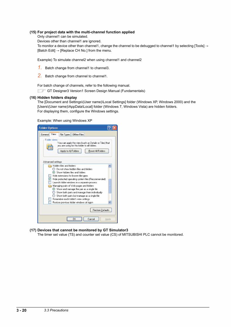
(15) For project data with the multi-channel function appliedOnly channel1 can be simulated.Devices other than channel1 are ignored.To monitor a device other than channel1, change the channel to be debugged to channel1 by selecting [Tools] [Batch Edit] [Replace CH No.] from the menu.
Example) To simulate channel2 when using channel1 and channel2
1. Batch change from channel1 to channel3.
2. Batch change from channel to channel1.
For batch change of channels, refer to the following manual.
GT Designer3 Version1 Screen Design Manual (Fundamentals)
(16) Hidden folders displayThe [Document and Settings\(User name)\Local Settings] folder (Windows XP, Windows 2000) and the [Users\(User name)\AppData\Local] folder (Windows 7, Windows Vista) are hidden folders.For displaying them, configure the Windows settings.
Example: When using Windows XP
(17) Devices that cannot be monitored by GT Simulator3The timer set value (TS) and counter set value (CS) of MITSUBISHI PLC cannot be monitored.
3 - 20 3.3 Precautions
1
OV
ER
VIE
W
2
SY
ST
EM
C
ON
FIG
UR
AT
ION
3
SP
EC
IFIC
AT
ION
S
4
SC
RE
EN
C
ON
FIG
UR
AT
ION
OF
G
T S
IMU
LAT
OR
3
5
GT
SIM
ULA
TO
R3
OP
ER
AT
ING
ME
TH
OD
6
FU
NC
TIO
NS
OF
G
T S
IMU
LA
TO
R3
7
DE
VIC
E M
ON
ITO
R
8
TR
OU
BLE
SH
OO
TIN
G
3.3.2 Precautions for connecting to GX Simulator or GX Simulator2
(1) When GX Simulator has been started from GT Simulator3GX Simulator cannot be started for being used on GX Developer.Exit from GT Simulator3, then restart GX Simulator from GX Developer.
(2) When GX Simulator has been started from GX Developer or GX Works2 has been started from GX Simulator2
(a) When GX Simulator has been started from GX Developer or GX Works2 has been started from GX Simulator2GX Simulator2 uses the GX Simulator started from GX Developer.
(b) When exiting GX Simulator or GX Simulator2Not that if you exit from GX Developer and GX Simulator first, GT Simulator2will result in a communication error.
(3) When simulating the project data in which a third party PLC is set for the PLC Type.
(a) When simulating with using [Default] of [GX Simulator setup]By setting the CPU type in [Option] of GT Simulator3 to [MELSEC-A], the simulation in the device ranges of
A4UCPU is possible. ( 5.3 Option Setting)Refer to the below for the device ranges that can be simulated.
3.4 Device Ranges that Can Be Simulated
(b) When simulating with using [GX Developer Project] of [GX Simulator setup]Specify GX Developer project whose PLC series is [ACPU].By setting the CPU type in [Option] of GT Simulator3 to [MELSEC-A], the simulation in the device ranges of
ACPU (Specified PLC type) is possible. ( 5.3 Option Setting)Refer to the below for the device ranges that can be simulated.
3.4 Device Ranges that Can Be Simulated
(4) When simulating a project data in which [LCPU] is set for the PLC series, with GX Simulator.Simulation can be performed in the Q26UDHCPU device range, by setting the CPU type in [Option] of GT
Simulator3 to [MELSEC-Q]. ( 5.3 Option Setting)For the device ranges that can be simulated, refer to the following.
3.4 Device Ranges that Can Be Simulated
(5) When simulating the project data whose PLC type is [FX3UC]When [GX Simulator setup] in [Option] of GT Simulator3 is set to [GX Developer Project], it is not possible to simulate by specifying a GX Developer project whose PLC type is [FX3UC].Set [GX Simulator setup] in [Option] of GT Simulator3 to [Default], then simulate in the device ranges of FX2N Series.
( 5.3 Option Setting)
(6) When simulating the buffer memoryBy setting [GX Simulator setup] in [Option] of GT Simulator3 to [GX Developer Project] and specifying an I/O-assigned GX Developer project, the buffer memory can be simulated.
( 5.3 Option Setting)The buffer memory cannot be simulated since I/O assignment has not been made, when [GX Simulator setup] in [Option] of GT Simulator3 is set to [Default].
POINTPOINTPOINT
Difference with debug executed by connecting to PLC CPU
Refer to the following manual for the difference with debug executed by connecting to PLC CPU.
GX Simulator Version Operating Manual
3.3 Precautions 3 - 21

3.3.3 Precautions for connecting PLC CPU
(1) When connecting GT Simulator3 to the function extension board of the FXCPUWhen connecting GT Simulator3 to the function extension board of the FXCPU, make the following settings on GX Developer.
1. Uncheck [Operate communication setting] on the PLC system (2) tab of [PLC Parameter].
2. Set "0" in special register (D8120) of FXCPU.
3 - 22 3.3 Precautions

1
OV
ER
VIE
W
2
SY
ST
EM
C
ON
FIG
UR
AT
ION
3
SP
EC
IFIC
AT
ION
S
4
SC
RE
EN
C
ON
FIG
UR
AT
ION
OF
G
T S
IMU
LAT
OR
3
5
GT
SIM
ULA
TO
R3
OP
ER
AT
ING
ME
TH
OD
6
FU
NC
TIO
NS
OF
G
T S
IMU
LA
TO
R3
7
DE
VIC
E M
ON
ITO
R
8
TR
OU
BLE
SH
OO
TIN
G
3.4 Device Ranges that Can Be Simulated
The following device ranges can be simulated on GT Simulator3.
3.4.1 Connecting to PLC CPU
It is possible to simulate the device ranges that can be monitored on GOT. Refer to the following manual for the device ranges that can be monitored on GOT.
• For GOT1000 series simulator
GT Designer3 Version1 Screen Design Manual (Fundamentals)
• For GOT-A900 series simulator
GT Designer2 Version Reference Manual
POINTPOINTPOINT
(1) Devices that cannot be monitored by GT Simulator3Refer to the below for devices that cannot be monitored by GT Simulator3.
3.3.1 Precautions for using the GT Simulator3
(2) PLC CPU that can be simulated on GT Simulator3Refer to the below for PLC CPU that can be simulated on GT Simulator3.
2.3 PLC CPUs that Can Be Simulated
3.4 Device Ranges that Can Be Simulated 3 - 23

3.4.2 Connecting to GX Simulator or GX Simlator2
POINTPOINTPOINT
(1) Devices unsupported by GX Simulator or GX Simulator2The devices unsupported by GX Simulator or GX Simulator2 cannot be simulated. Refer to the following manual for the device ranges supported by GX Simulator or GX Simulator2.
GX Simulator Version Operating Manual
GX Works2 Version Operating Manual
(2) PLC CPU that can be simulated on GT Simulator3Refer to the following manual for PLC CPU that can be simulated on GT Simulator3.
2.3 PLC CPUs that Can Be Simulated
MITSUBISHI PLCIt is possible to simulate the device ranges that can be monitored on GOT. Refer to the following manual for the device ranges that can be monitored on GOT.
• For GOT1000 series simulator
GT Designer3 Version1 Screen Design Manual (Fundamentals)
• For GOT-A900 series simulator
GT Designer2 Version Reference Manual
3 - 24 3.4 Device Ranges that Can Be Simulated

1
OV
ER
VIE
W
2
SY
ST
EM
C
ON
FIG
UR
AT
ION
3
SP
EC
IFIC
AT
ION
S
4
SC
RE
EN
C
ON
FIG
UR
AT
ION
OF
G
T S
IMU
LAT
OR
3
5
GT
SIM
ULA
TO
R3
OP
ER
AT
ING
ME
TH
OD
6
FU
NC
TIO
NS
OF
G
T S
IMU
LA
TO
R3
7
DE
VIC
E M
ON
ITO
R
8
TR
OU
BLE
SH
OO
TIN
G
OMRON PLC (OMRON SYSMAC)
*1 For precautions when using each device that can be monitored by GOT, refer to the following manual.
• For GOT1000 series simulator
GT Designer3 Version1 Screen Design Manual (Fundamentals)
• For GOT-A900 series simulator
GT Designer2 Version Reference Manual
*2 In parentheses, the device ranges of GOT-A900 Series is indicated.
Device name GOT monitoring available range *1
Available range for simulating with
GT Simulator3
(The operable range on GX Simulator or GX
Simulator2)
Bit
dev
ice
I/O relay/Internal auxiliary relay (..) ..000000 to ..614315 ..000000 to ..008115
Data link relay (LR) LR00000 to LR19915 LR00000 to LR08115
Auxiliary memory relay (AR) AR00000 to AR95915 -
Holding relay (HR) HR00000 to HR51115 HR00000 to HR08115
Internal auxiliary relay/Work relay(WR) WR00000 to WR51115 WR00000 to WR08115
Timer contact (TIM) TIM0000 to TIM4095 (TIM2047)*2 TIM0000 to TIM0255
Counter contact (CNT) CNT0000 to CNT4095 (CNT2047)*2 CNT0000 to CNT0255
Word device bit
Specified bits of the following word devices
(Except for data link relay, auxiliary memory
relay, holding relay and internal auxiliary relay.)
Specified bits of the following word devices
(Except for data link relay, auxiliary memory
relay, holding relay and internal auxiliary relay.)
Wo
rd d
evi
ce
I/O relay/Internal auxiliary relay (..) ..0000 to ..6143 ..0000 to ..0081
Data link relay (LR) LR000 to LR199 LR000 to LR081
Auxiliary memory relay (AR) AR000 to AR959 -
Holding relay (HR) HR000 to HR511 HR000 to HR081
Internal auxiliary relay/Work relay(WR) WR000 to WR511 WR000 to WR081
Data memory (DM) DM00000 to DM32767 (DM9999)*2 DM0000 to DM8191
Timer (current value) (TIM) TIM0000 to TIM4095 (TIM2047)*2 TIM0000 to TIM0255
Counter (current value) (CNT) CNT0000 to CNT4095 (CNT2047)*2 CNT0000 to CNT0255
Extended data memory
(EM current bank)EM00000 to EM32767 (EM9999)*2 -
Extended data memory
(EM banks 0 to 13)
E000000 to E032767 (E09999)*2
•
•
EC00000 to EC32767 (EC9999)*2
-
3.4 Device Ranges that Can Be Simulated 3 - 25
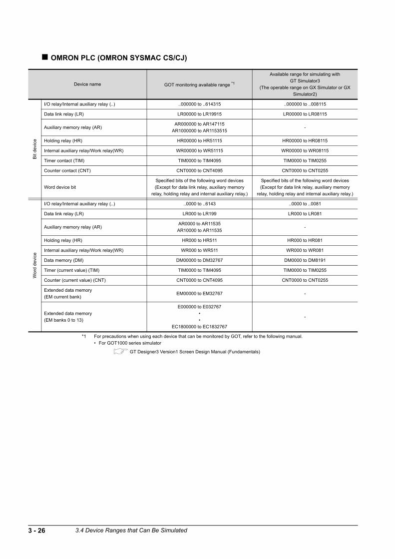
OMRON PLC (OMRON SYSMAC CS/CJ)
*1 For precautions when using each device that can be monitored by GOT, refer to the following manual.
• For GOT1000 series simulator
GT Designer3 Version1 Screen Design Manual (Fundamentals)
Device name GOT monitoring available range *1
Available range for simulating with
GT Simulator3
(The operable range on GX Simulator or GX
Simulator2)
Bit
devi
ce
I/O relay/Internal auxiliary relay (..) ..000000 to ..614315 ..000000 to ..008115
Data link relay (LR) LR00000 to LR19915 LR00000 to LR08115
Auxiliary memory relay (AR)AR000000 to AR147115
AR1000000 to AR1153515-
Holding relay (HR) HR00000 to HR51115 HR00000 to HR08115
Internal auxiliary relay/Work relay(WR) WR00000 to WR51115 WR00000 to WR08115
Timer contact (TIM) TIM0000 to TIM4095 TIM0000 to TIM0255
Counter contact (CNT) CNT0000 to CNT4095 CNT0000 to CNT0255
Word device bit
Specified bits of the following word devices
(Except for data link relay, auxiliary memory
relay, holding relay and internal auxiliary relay.)
Specified bits of the following word devices
(Except for data link relay, auxiliary memory
relay, holding relay and internal auxiliary relay.)
Wo
rd d
evi
ce
I/O relay/Internal auxiliary relay (..) ..0000 to ..6143 ..0000 to ..0081
Data link relay (LR) LR000 to LR199 LR000 to LR081
Auxiliary memory relay (AR)AR0000 to AR11535
AR10000 to AR11535-
Holding relay (HR) HR000 to HR511 HR000 to HR081
Internal auxiliary relay/Work relay(WR) WR000 to WR511 WR000 to WR081
Data memory (DM) DM00000 to DM32767 DM0000 to DM8191
Timer (current value) (TIM) TIM0000 to TIM4095 TIM0000 to TIM0255
Counter (current value) (CNT) CNT0000 to CNT4095 CNT0000 to CNT0255
Extended data memory
(EM current bank)EM00000 to EM32767 -
Extended data memory
(EM banks 0 to 13)
E000000 to E032767
•
•
EC1800000 to EC1832767
-
3 - 26 3.4 Device Ranges that Can Be Simulated

1
OV
ER
VIE
W
2
SY
ST
EM
C
ON
FIG
UR
AT
ION
3
SP
EC
IFIC
AT
ION
S
4
SC
RE
EN
C
ON
FIG
UR
AT
ION
OF
G
T S
IMU
LAT
OR
3
5
GT
SIM
ULA
TO
R3
OP
ER
AT
ING
ME
TH
OD
6
FU
NC
TIO
NS
OF
G
T S
IMU
LA
TO
R3
7
DE
VIC
E M
ON
ITO
R
8
TR
OU
BLE
SH
OO
TIN
G
KEYENCE PLC (KEYENCE KV-700/1000/3000/5000)
*1 For precautions when using each device that can be monitored by GOT, refer to the following manual.
• For GOT1000 series simulator
GT Designer3 Version1 Screen Design Manual (Fundamentals)
Device name GOT monitoring available range *1
Available range for simulating with
GT Simulator3
(The operable range on GX Simulator or GX
Simulator2)
Bit
de
vice
Relay (..) ..00000 to ..59915 ..00000 to ..51115
Internal AUX relay (MR) MR00000 to MR99915 MR00000 to MR51115
Latch relay (LR) LR00000 to LR99915 LR00000 to LR51115
Control relay (CR) CR0000 to CR3915 CR0000 to CR1515
Timer (contact) (T) T0000 to T3999 T0000 to T0255
Counter (contact) (C) C0000 to C3999 C0000 to C0255
High-speed counter comparators (contact)
(CTC)CTC0 to CTC3 -
Word device bit
Specified bits of the following word devices
(Except for Timer (current value), Timer (set
value), Counter (current value), Counter (set
value), High-speed counter (current value), High-
speed counter comparators (set value), Control
memory, Temparary data memory, Index register,
Digital trimer.)
Specified bits of the following word devices
(Except for Timer (current value), Timer (set
value), Counter (current value), Counter (set
value), High-speed counter (current value), High-
speed counter comparators (set value), Control
memory, Temparary data memory, Index register,
Digital trimer.)
Wo
rd d
evi
ce
Relay (..) ..00000 to ..59900 ..00000 to ..51100
Internal AUX relay (MR) MR00000 to MR99900 MR00000 to MR51100
Latch relay (LR) LR00000 to LR99900 LR00000 to LR51100
Control relay (CR) CR0000 to CR3900 CR0000 to CR1500
Timer (current value) (TC) TC0000 to TC3999 TC0000 to TC0254
Timer (set value) (TS) TS0000 to TS3999 -
Counter (current value) (CC) CC0000 to CC3999 CC0000 to CC0254
Counter (set value) (CS) CS0000 to CS3999 -
High-speed counter (current value) (CTH) CTH0 to CTH1 -
High-speed counter comparators (set value)
(CTC)CTC0 to CTC3 -
Data memory (DM) DM00000 to DM65534 DM0000 to DM8191
Extended data memory (EM) EM00000 to EM65534 -
Extended data memory 2 (FM) FM00000 to FM32766 -
Control memory (CM) CM00000 to CM11998 -
Temporary data memory (TM) TM000 to TM511 -
Index register (Z) Z01 to Z12 Z01 to Z06
Digital trimmer (TRM) TRM0 to TRM7 -
3.4 Device Ranges that Can Be Simulated 3 - 27

KOYO EI PLC (KOYO KOSTAC/DL)
*1 For precautions when using each device that can be monitored by GOT, refer to the following manual.
• For GOT1000 series simulator
GT Designer3 Version1 Screen Design Manual (Fundamentals)
• For GOT-A900 series simulator
GT Designer2 Version Reference Manual
Device name GOT monitoring available range *1
Available range for simulating with
GT Simulator3
(The operable range on GX Simulator or GX
Simulator2)
Bit
devi
ce
Input (I) I0 to I1777 I0 to I1777
Output (Q) Q0 to Q1777 Q0 to Q1777
Link relay (GI) GI0 to GI3777 GI0 to GI3777
Link output (GQ) GQ0 to GQ3777 -
Internal relay (M) M0 to M3777 M0 to M3777
Stage (S) S0 to S1777 -
Timer (T) T0 to T377 T0 to T377
Counter (C) C0 to C377 C0 to C377
Special relay (SP) SP0 to SP777 -
Wo
rd d
evi
ce
Timer (current value) (R) R0 to R377 R0 to R377
Preparatory register (R) R400 to R677 R400 to R677
Special register 1 (R) R700 to R777 R700 to R777
Counter (current value) (R) R1000 to R1377 R1000 to R1377
Data register 1 (R) R1400 to R7377 R1400 to R7377
Special register 2 (R) R7400 to R7777 R7400 to R7777
Data register 2 (R) R10000 to R36777 R10000 to R36777
Special register 3 (R) R37000 to R37777 R37000 to R37777
Link relay (R) R40000 to R40177 R40000 to R40177
Link output (R) R40200 to R40377 R40200 to R40377
Input (R) R40400 to R40477 R40400 to R40477
Output (R) R40500 to R40577 R40500 to R40577
Internal relay (R) R40600 to R40777 R40600 to R40777
Stage (R) R41000 to R41077 R41000 to R41077
Timer (R) R41100 to R41117 R41100 to R41117
Counter (R) R41140 to R41157 R41140 to R41157
Special relay (R) R41200 to R41237 R41200 to R41237
3 - 28 3.4 Device Ranges that Can Be Simulated

1
OV
ER
VIE
W
2
SY
ST
EM
C
ON
FIG
UR
AT
ION
3
SP
EC
IFIC
AT
ION
S
4
SC
RE
EN
C
ON
FIG
UR
AT
ION
OF
G
T S
IMU
LAT
OR
3
5
GT
SIM
ULA
TO
R3
OP
ER
AT
ING
ME
TH
OD
6
FU
NC
TIO
NS
OF
G
T S
IMU
LA
TO
R3
7
DE
VIC
E M
ON
ITO
R
8
TR
OU
BLE
SH
OO
TIN
G
SHARP PLC (SHARP JW)
*1 For precautions when using each device that can be monitored by GOT, refer to the following manual.
• For GOT1000 series simulator
GT Designer3 Version1 Screen Design Manual (Fundamentals)
• For GOT-A900 series simulator
GT Designer2 Version Reference Manual
Device name GOT monitoring available range *1
Available range for simulating with
GT Simulator3
(The operable range on GX Simulator or GX
Simulator2)
Bit
de
vice
I/O relay..00000 to ..15777
..20000 to ..75777..00000 to ..15777
Timer (contact) (T) T0000 to T1777 T0000 to T0377
Counter (contact) (C) C0000 to C1777 C0000 to C0377
Word device bit Specified bits of the following word devices Specified bits of the following word devices
Wo
rd d
evi
ce
Timer (current value) (T) T0000 to T1777 T0000 to T0377
Counter (current value) (C) C0000 to C1777 C0000 to C0377
Register (09 to E7)
09000 to 09776 09000 to 09776
19000 to 19776 19000 to 19776
29000 to 29776 29000 to 29776
39000 to 39776 39000 to 39776
49000 to 49776 49000 to 49776
59000 to 59776 59000 to 59776
69000 to 69776 69000 to 69776
79000 to 79776 79000 to 79776
89000 to 89776 89000 to 89776
99000 to 99776 99000 to 99776
E0000 to E0776 E0000 to E0776
E1000 to E1776 E1000 to E1776
E2000 to E2776 E2000 to E2776
E3000 to E3776 E3000 to E3776
E4000 to E4776 E4000 to E4776
E5000 to E5776 E5000 to E5776
E6000 to E6776 -
E7000 to E7776 E7450 to E7776
File register (1 to 7)
1000000 to 1177776
2000000 to 2177776
3000000 to 3177776
4000000 to 4177776
5000000 to 5177776
6000000 to 6177776
7000000 to 7177776
-
Bit device wordConversion of the above bit devices to words
(Except Timer and Counter)
Conversion of the above bit devices to words
(Except Timer and Counter)
3.4 Device Ranges that Can Be Simulated 3 - 29
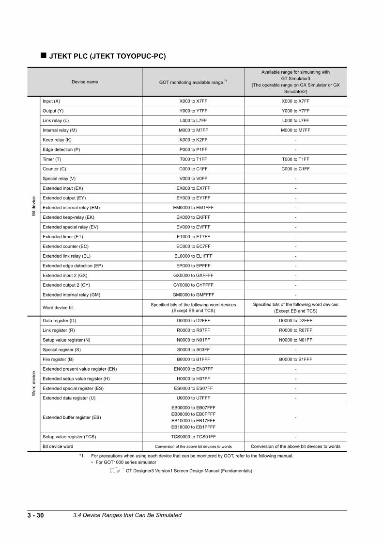
JTEKT PLC (JTEKT TOYOPUC-PC)
*1 For precautions when using each device that can be monitored by GOT, refer to the following manual.
• For GOT1000 series simulator
GT Designer3 Version1 Screen Design Manual (Fundamentals)
Device name GOT monitoring available range *1
Available range for simulating with
GT Simulator3
(The operable range on GX Simulator or GX
Simulator2)
Bit
de
vice
Input (X) X000 to X7FF X000 to X7FF
Output (Y) Y000 to Y7FF Y000 to Y7FF
Link relay (L) L000 to L7FF L000 to L7FF
Internal relay (M) M000 to M7FF M000 to M7FF
Keep relay (K) K000 to K2FF -
Edge detection (P) P000 to P1FF -
Timer (T) T000 to T1FF T000 to T1FF
Counter (C) C000 to C1FF C000 to C1FF
Special relay (V) V000 to V0FF -
Extended input (EX) EX000 to EX7FF -
Extended output (EY) EY000 to EY7FF -
Extended internal relay (EM) EM0000 to EM1FFF -
Extended keep-relay (EK) EK000 to EKFFF -
Extended special relay (EV) EV000 to EVFFF -
Extended timer (ET) ET000 to ET7FF -
Extended counter (EC) EC000 to EC7FF -
Extended link relay (EL) EL0000 to EL1FFF -
Extended edge detection (EP) EP000 to EPFFF -
Extended input 2 (GX) GX0000 to GXFFFF -
Extended output 2 (GY) GY0000 to GYFFFF -
Extended internal relay (GM) GM0000 to GMFFFF -
Word device bitSpecified bits of the following word devices
(Except EB and TCS)Specified bits of the following word devices
(Except EB and TCS)
Wo
rd d
evic
e
Data register (D) D0000 to D2FFF D0000 to D2FFF
Link register (R) R0000 to R07FF R0000 to R07FF
Setup value register (N) N0000 to N01FF N0000 to N01FF
Special register (S) S0000 to S03FF -
File register (B) B0000 to B1FFF B0000 to B1FFF
Extended present value register (EN) EN0000 to EN07FF -
Extended setup value register (H) H0000 to H07FF -
Extended special register (ES) ES0000 to ES07FF -
Extended data register (U) U0000 to U7FFF -
Extended buffer register (EB)
EB00000 to EB07FFF
EB08000 to EB0FFFF
EB10000 to EB17FFF
EB18000 to EB1FFFF
-
Setup value register (TCS) TCS0000 to TCS01FF -
Bit device word Conversion of the above bit devices to words Conversion of the above bit devices to words
3 - 30 3.4 Device Ranges that Can Be Simulated

1
OV
ER
VIE
W
2
SY
ST
EM
C
ON
FIG
UR
AT
ION
3
SP
EC
IFIC
AT
ION
S
4
SC
RE
EN
C
ON
FIG
UR
AT
ION
OF
G
T S
IMU
LAT
OR
3
5
GT
SIM
ULA
TO
R3
OP
ER
AT
ING
ME
TH
OD
6
FU
NC
TIO
NS
OF
G
T S
IMU
LA
TO
R3
7
DE
VIC
E M
ON
ITO
R
8
TR
OU
BLE
SH
OO
TIN
G
TOSHIBA PLC (TOSHIBA PROSEC T,V Series)
*1 For precautions when using each device that can be monitored by GOT, refer to the following manual.
• For GOT1000 series simulator
GT Designer3 Version1 Screen Design Manual (Fundamentals)
• For GOT-A900 series simulator
GT Designer2 Version Reference Manual
Device name GOT monitoring available range *1
Available range for simulating with
GT Simulator3
(The operable range on GX Simulator or GX
Simulator2)
Bit
de
vice
External input (X) X0000 to X511F X0000 to X511F
External output (Y) Y0000 to Y511F Y0000 to Y511F
Internal relay (R) R0000 to R4095F R0000 to R0511F
Special relay (S) S0000 to S511F -
Link register relay (Z) Z0000 to Z999F Z0000 to Z511F
Link relay (L) L0000 to L255F -
Timer (contact) (T) T0 to T999 T0 to T255
Counter (contact) (C) C0 to C511 C0 to C255
Word device bit
Specified bits of the following word devices
(Only for data register, link register and file
register)
Specified bits of the following word devices
(Only for data register, link register and file
register)
Wor
d d
evi
ce
External input (XW) XW0 to XW511 XW0 to XW511
External output (YW) YW0 to YW511 YW0 to YW511
Internal relay (RW) RW0 to RW4095 RW0 to RW4095
Special relay (SW) SW0 to SW511 -
Link relay (LW) LW0 to LW255 -
Timer (current value) (T) T0 to T999 T0 to T255
Counter (current value) (C) C0 to C511 C0 to C255
Data register (D) D0 to D8191 D0 to D8191
Link register (W) W0 to W2047 W0 to W2047
File register (F) F0 to F32767 -
3.4 Device Ranges that Can Be Simulated 3 - 31

TOSHIBA MACHINE PLC (TOSHIBA MACHINE TCmini)
*1 For precautions when using each device that can be monitored by GOT, refer to the following manual.
• For GOT1000 series simulator
GT Designer3 Version1 Screen Design Manual (Fundamentals)
• For GOT-A900 series simulator
GT Designer2 Version Reference Manual
Device name GOT monitoring available range *1
Available range for simulating with
GT Simulator3
(The operable range on GX Simulator or GX
Simulator2)
Bit
devi
ce
Input relay 1 (X) X000 to XF7F X000 to XF7F
Input relay 2 (I) I000 to IF7F -
Output relay 1 (Y) Y000 to YF7F Y000 to YF7F
Output relay 2 (O) O000 to OF7F -
Internal relay (R) R000 to R77F R000 to R77F
Extended internal relay 1 (GR) GR000 to GRF7F -
Extended internal relay 2 (H) H000 to HF7F -
Extended internal relay 3 (J) J000 to JF7F -
Extended internal relay 4 (K) K000 to KF7F -
Timer contact (T) T000 to T77F T000 to T17F
Counter contact (C) C000 to C77F C000 to C17F
Shift relay (S) S000 to S07F -
Latch relay (L) L000 to L07F L000 to L07F
Edge relay (E) E000 to E77F E000 to E77F
Special aux relay (A) A000 to A16F A000 to A16F
Wo
rd d
evic
e
Input register 1 (XW) XW00 to XWF7 XW00 to XWF7
Input register 2 (IW) IW00 to IWF7 -
Output register 1 (YW) YW00 to YWF7 YW00 to YWF7
Output register 2 (OW) OW00 to OWF7 -
Internal register (RW) RW00 to RW77 RW00 to RW77
Extended internal register 1 (GW) GW00 to GWF7 -
Extended internal register 2 (HW) HW00 to HWF7 -
Extended internal register 3 (JW) JW00 to JWF7 -
Extended internal register 4 (KW) KW00 to KWF7 -
Timer contact register (TW) TW00 to TW77 TW00 to TW17
Counter contact register (CW) CW00 to CW77 CW00 to CW17
Shift register (SW) SW00 to SW07 -
Latch register (LW) LW00 to LW07 LW00 to LW07
Edge register (EW) EW00 to EW77 EW00 to EW77
Special aux register (AW) AW00 to AW16 AW00 to AW16
Generic register 1 (D) D000 to DF7F D000 to DF7F
Generic register 2 (B) B000 to BF7F -
Generic register 3 (U) U000 to UF7F -
Generic register 4 (M) M000 to MF7F -
Generic register 5 (Q) Q000 to QF7F -
Timer/Counter current value (P) P000 to P77F P000 to P17F
Timer/Counter set value (V) V000 to V77F -
3 - 32 3.4 Device Ranges that Can Be Simulated
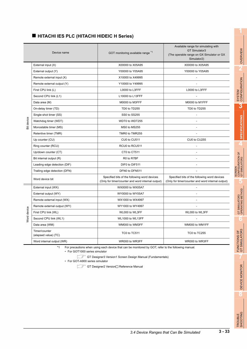
1
OV
ER
VIE
W
2
SY
ST
EM
C
ON
FIG
UR
AT
ION
3
SP
EC
IFIC
AT
ION
S
4
SC
RE
EN
C
ON
FIG
UR
AT
ION
OF
G
T S
IMU
LAT
OR
3
5
GT
SIM
ULA
TO
R3
OP
ER
AT
ING
ME
TH
OD
6
FU
NC
TIO
NS
OF
G
T S
IMU
LA
TO
R3
7
DE
VIC
E M
ON
ITO
R
8
TR
OU
BLE
SH
OO
TIN
G
HITACHI IES PLC (HITACHI HIDEIC H Series)
*1 For precautions when using each device that can be monitored by GOT, refer to the following manual.
• For GOT1000 series simulator
GT Designer3 Version1 Screen Design Manual (Fundamentals)
• For GOT-A900 series simulator
GT Designer2 Version Reference Manual
Device name GOT monitoring available range *1
Available range for simulating with
GT Simulator3
(The operable range on GX Simulator or GX
Simulator2)
Bit
de
vice
External input (X) X00000 to X05A95 X00000 to X05A95
External output (Y) Y00000 to Y05A95 Y00000 to Y05A95
Remote external input (X) X10000 to X49995 -
Remote external output (Y) Y10000 to Y49995 -
First CPU link (L) L0000 to L3FFF L0000 to L3FFF
Second CPU link (L1) L10000 to L13FFF -
Data area (M) M0000 to M3FFF M0000 to M1FFF
On-delay timer (TD) TD0 to TD255 TD0 to TD255
Single-shot timer (SS) SS0 to SS255 -
Watchdog timer (WDT) WDT0 to WDT255 -
Monostable timer (MS) MS0 to MS255 -
Retentive timer (TMR) TMR0 to TMR255 -
Up counter (CU) CU0 to CU511 CU0 to CU255
Ring counter (RCU) RCU0 to RCU511 -
Up/down counter (CT) CT0 to CT511 -
Bit internal output (R) R0 to R7BF -
Leading edge detection (DIF) DIF0 to DIF511 -
Trailing edge detection (DFN) DFN0 to DFN511 -
Word device bitSpecified bits of the following word devices
(Only for timer/counter and word internal output)
Specified bits of the following word devices
(Only for timer/counter and word internal output)
Wo
rd d
evic
e
External input (WX) WX0000 to WX05A7 -
External output (WY) WY0000 to WY05A7 -
Remote external input (WX) WX1000 to WX4997 -
Remote external output (WY) WY1000 to WY4997 -
First CPU link (WL) WL000 to WL3FF WL000 to WL3FF
Second CPU link (WL1) WL1000 to WL13FF -
Data area (WM) WM000 to WM3FF WM000 to WM1FF
Timer/counter
(elapsed value) (TC)TC0 to TC511 TC0 to TC255
Word internal output (WR) WR000 to WR3FF WR000 to WR3FF
3.4 Device Ranges that Can Be Simulated 3 - 33

HITACHI PLC (Hitachi S10mini/S10V)
(Continued to next page)
Device name Monitor applicable range for GOT *1
Available range for simulating with
GT Simulator3
(The operable range on GX Simulator or GX
Simulator2)
Bit
de
vice
External input (X) X000 to XFFF X000 to XFFF
External output (Y) Y000 to YFFF Y000 to YFFF
Internal register (R) R000 to RFFF R000 to RFFF
Keep relay (K) K000 to KFFF K000 to KFFF
Extended internal register (M) M000 to MFFF M000 to MFFF
Extended internal register (A) A000 to AFFF -
On-delay timer (T) T000 to T1FF T000 to T1FF
One-shot timer (U) U000 to U0FF -
Up-down counter (C) C00 to CFF C00 to CFF
Global link register (G) G000 to GFFF G000 to GFFF
Event register (E) E000 to EFFF E000 to EFFF
System register (S) S000 to SBFF S000 to S0FF
Transfer register (J) J000 to JFFF -
Receive register (Q) Q000 to QFFF -
Word device bit
Specified bit of the following word device
(except External input, External output, Internal
register, Extended internal register, Keep relay,
On-delay timer, One-shot timer, Up-down
counter, Global link register, Event register,
System register, Transfer register, Receive
register, Long-word work register, Floating-point
work register, Backup single-precision floating-
point work register.)
3 - 34 3.4 Device Ranges that Can Be Simulated

1
OV
ER
VIE
W
2
SY
ST
EM
C
ON
FIG
UR
AT
ION
3
SP
EC
IFIC
AT
ION
S
4
SC
RE
EN
C
ON
FIG
UR
AT
ION
OF
G
T S
IMU
LAT
OR
3
5
GT
SIM
ULA
TO
R3
OP
ER
AT
ING
ME
TH
OD
6
FU
NC
TIO
NS
OF
G
T S
IMU
LA
TO
R3
7
DE
VIC
E M
ON
ITO
R
8
TR
OU
BLE
SH
OO
TIN
G
*1 For precautions when using each device that can be monitored by GOT, refer to the following manual.
• For GOT1000 series simulator
GT Designer3 Version1 Screen Design Manual (Fundamentals)
Device name Monitor applicable range for GOT *1
Available range for simulating with
GT Simulator3
(The operable range on GX Simulator or GX
Simulator2)
Wor
d d
evi
ce
External input (XW) XW000 to XWFF0 XW000 to XWFF0
External output (YW) YW000 to YWFF0 YW000 to YWFF0
Internal register (RW) RW000 to RWFF0 RW000 to RWFF0
Extended internal register (MW) MW000 to MWFF0 MW000 to MWFF0
Extended internal register (AW) AW000 to AWFF0 -
Keep relay (KW) KW000 to KWFF0 KW000 to KWFF0
On-delay timer (TW) TW000 to TW1F0 TW000 to TW1F0
One-shot timer (UW) UW000 to UW0F0 -
Up-down counter (CW) CW00 to CWF0 CW00 to CWF0
Global link register (GW) GW000 to GWFF0 GW000 to GWFF0
Event register (EW) EW000 to EWFF0 EW000 to EWFF0
System register (SW) SW000 to SWBF0 SW000 to SW0F0
Transfer register (JW) JW000 to JWFF0 -
Receive register (QW) QW000 to QWFF0 -
On-delay timer (current value) (TC) TC000 to TC1FF TC000 to TC1FF
On-delay timer (current value) (TS) TS000 to TS1FF -
One-shot timer (current value) (UC) UC000 to UC0FF -
One-shot timer (current value) (US) US000 to US0FF -
Up-down counter (current value) (CC) CC00 to CCFF CC00 to CCFF
Up-down counter (current value) (CS) CS00 to CSFF -
Function data register (DW) DW000 to DWFFF DW000 to DWFFF
Function work register (FW) FW000 to FWBFF -
Extended function work register (LWW) LWW0000 to LWWFFFF -
Backup work register (LXW) LXW0000 to LXW3FFF -
Long-word work register (LLL) LLL0000 to LLL1FFF -
Backup long-word work register (LML) LML0000 to LML1FFF -
Floating-point work register (LF) LF0000 to LF1FFF -
Backup single-precision floating-point work
register (LG)LG0000 to LG1FFF -
3.4 Device Ranges that Can Be Simulated 3 - 35

FUJI FA PLC (Fuji Electric FA Components & Systems MICREX-F series)
*1 For precautions when using each device that can be monitored by GOT, refer to the following manual.
• For GOT1000 series simulator
GT Designer3 Version1 Screen Design Manual(Fundamentals)
Device name Monitor applicable range for GOT *1
Available range for simulating with
GT Simulator3
(The operable range on GX Simulator or GX
Simulator2)
Bit
de
vice
I/O relay (B) B0000 to B511F B0000 to B511F
Auxiliary relay (M) M0000 to M511F M0000 to M511F
Keep relay (K) K0000 to K063F K0000 to K063F
Special relay (F) F0000 to F125F F0000 to F015F
Annunciator relay (A) A0000 to A045F A0000 to A045F
Differential relay (D) D0000 to D036F -
Link memory (L) L0000 to L511F L0000 to L511F
Timer output (0.01second) (T) T000 to T511 T000 to T511
Timer output (0.1second) (T) T512 to T999 T512 to T999
Counter output (C) C000 to C511 C000 to C511
Word device bit
Specified bits of the following word device
(except I/O relay, Auxiliary relay, Keep relay,
Special relay, Annunciator relay, Differential
relay, Link memory, Data memory, Timer,
Counter.)
Specified bits of the following word device
(except I/O relay, Auxiliary relay, Keep relay,
Special relay, Annunciator relay, Differential
relay, Link memory, Data memory, Timer,
Counter.)
Wor
d d
evi
ce
I/O relay (WB) WB000 to WB511 WB000 to WB511
Auxiliary relay (WM) WM000 to WM511 WM000 to WM511
Keep relay (WK) WK000 to WK063 WK000 to WK063
Special relay (WF) WF000 to WF125 WF000 to WF015
Annunciator relay (WA) WA000 to WA045 WA000 to WA045
Differential relay (WD) WD000 to WD063 -
Link memory (WL) WL000 to WL511 WL000 to WL511
Direct access (W24) W24: 0000 to W24: 0255 -
User file (W30)
User file (W31)
•
•
User file (W108)
User file (W109)
W30: 0000 to W30: 4095
W31: 0000 to W31: 4095
•
•
W108: 0000 to W108: 4095
W109: 0000 to W109: 4095
-
Data memory (BD) BD0 to BD4095 BD0 to BD4095
Timer set value (0.01second) (TS) TS0 to TS511 -
Timer current value (0.01second) (TR) TR0 to TR511 -
Timer current value (0.1second) (W9) W9: 0000 to W9: 0487 W9: 0000 to W9: 0487
Counter set value (CS) CS0 to CS511 -
Counter current value (CR) CR0 to CR511 CR0 to CR511
3 - 36 3.4 Device Ranges that Can Be Simulated
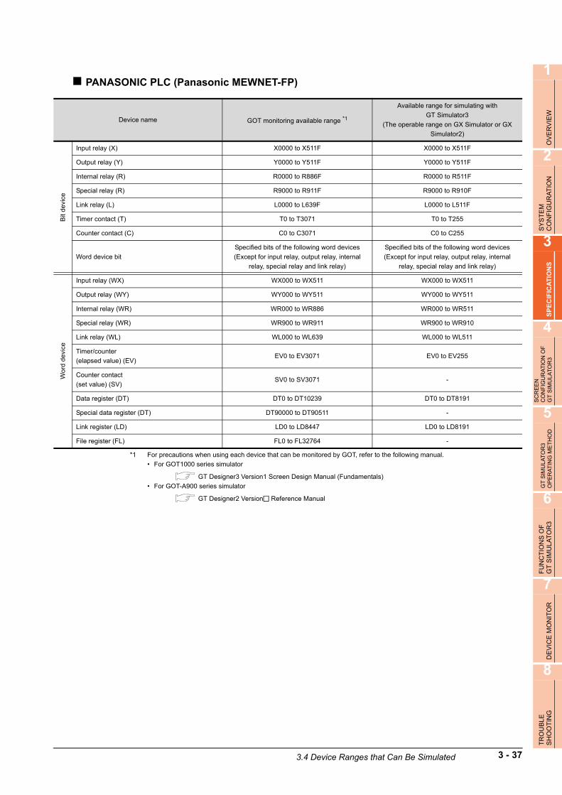
1
OV
ER
VIE
W
2
SY
ST
EM
C
ON
FIG
UR
AT
ION
3
SP
EC
IFIC
AT
ION
S
4
SC
RE
EN
C
ON
FIG
UR
AT
ION
OF
G
T S
IMU
LAT
OR
3
5
GT
SIM
ULA
TO
R3
OP
ER
AT
ING
ME
TH
OD
6
FU
NC
TIO
NS
OF
G
T S
IMU
LA
TO
R3
7
DE
VIC
E M
ON
ITO
R
8
TR
OU
BLE
SH
OO
TIN
G
PANASONIC PLC (Panasonic MEWNET-FP)
*1 For precautions when using each device that can be monitored by GOT, refer to the following manual.
• For GOT1000 series simulator
GT Designer3 Version1 Screen Design Manual (Fundamentals)
• For GOT-A900 series simulator
GT Designer2 Version Reference Manual
Device name GOT monitoring available range *1
Available range for simulating with
GT Simulator3
(The operable range on GX Simulator or GX
Simulator2)
Bit
de
vice
Input relay (X) X0000 to X511F X0000 to X511F
Output relay (Y) Y0000 to Y511F Y0000 to Y511F
Internal relay (R) R0000 to R886F R0000 to R511F
Special relay (R) R9000 to R911F R9000 to R910F
Link relay (L) L0000 to L639F L0000 to L511F
Timer contact (T) T0 to T3071 T0 to T255
Counter contact (C) C0 to C3071 C0 to C255
Word device bit
Specified bits of the following word devices
(Except for input relay, output relay, internal
relay, special relay and link relay)
Specified bits of the following word devices
(Except for input relay, output relay, internal
relay, special relay and link relay)
Wo
rd d
evi
ce
Input relay (WX) WX000 to WX511 WX000 to WX511
Output relay (WY) WY000 to WY511 WY000 to WY511
Internal relay (WR) WR000 to WR886 WR000 to WR511
Special relay (WR) WR900 to WR911 WR900 to WR910
Link relay (WL) WL000 to WL639 WL000 to WL511
Timer/counter
(elapsed value) (EV)EV0 to EV3071 EV0 to EV255
Counter contact
(set value) (SV)SV0 to SV3071 -
Data register (DT) DT0 to DT10239 DT0 to DT8191
Special data register (DT) DT90000 to DT90511 -
Link register (LD) LD0 to LD8447 LD0 to LD8191
File register (FL) FL0 to FL32764 -
3.4 Device Ranges that Can Be Simulated 3 - 37

YASKAWA PLC
(1) YASKAWA GL/PROGIC8
*1 For precautions when using each device that can be monitored by GOT, refer to the following manual.
• For GOT1000 series simulator
GT Designer3 Version1 Screen Design Manual (Fundamentals)
• For GOT-A900 series simulator
GT Designer2 Version Reference Manual
(2) YASKAWA CP-9200SH/MP900 Series
*2 For precautions when using each device that can be monitored by GOT, refer to the following manual.
• For GOT1000 series simulator
GT Designer3 Version1 Screen Design Manual (Fundamentals)
• For GOT-A900 series simulator
GT Designer2 Version Reference Manual
Device name GOT monitoring available range *1
Available range for simulating with
GT Simulator3
(The operable range on GX Simulator or GX
Simulator2)
Bit
devi
ce
Coil (O) O1 to O63424 O1 to O8176
Input relay (I) I1 to I63424 I1 to I8176
Link coil (D)
D1 to D2048 D1 to D2048
D10001 to D12048
D20001 to D22048-
Word device bit Specified bits of the following word devices Specified bits of the following word devices
Wo
rd d
evi
ce
Input register (Z) Z1 to Z31840Z1 to Z8192
Z9000 to Z9256
Holding register (W)W1 to W28291 -
SW1 to SW28291 -
Link register (R, SR)
R1 to R2048 R1 to R2048
R10001 to R12048
R20001 to R22048-
SR1 to SR2048 -
SR10001 to SR12048
SR20001 to SR22048-
Constant register (K) K1 to K4096 K1 to K6
Bit device wordConversion of the above bit devices to words
(Except coil and input relay)
Conversion of the above bit devices to words
(Except coil and input relay)
Device name GOT monitoring available range *2
Available range for simulating with
GT Simulator3
(The operable range on GX Simulator or GX
Simulator2)
Bit
de
vice
Coil (MB) MB000000 to MB32767F MB000000 to MB00511F
Input relay (IB) IB0000 to IBFFFF IB0000 to IB1FFF
Word device bitSpecified bits of the following word devices
(Except for coil and input relay)
Specified bits of the following word devices
(Except for coil and input relay)
Wo
rd d
evi
ce
Input register (IW) IW0000 to IW7FFF IW0000 to IW1FFF
Holding register (MW) MW0 to MW32767 -
Coil (MB) MB0 to MB32767 MB0 to MB511
Input relay (IB) IB000 to IBFFF IB000 to IBFFF
3 - 38 3.4 Device Ranges that Can Be Simulated

1
OV
ER
VIE
W
2
SY
ST
EM
C
ON
FIG
UR
AT
ION
3
SP
EC
IFIC
AT
ION
S
4
SC
RE
EN
C
ON
FIG
UR
AT
ION
OF
G
T S
IMU
LAT
OR
3
5
GT
SIM
ULA
TO
R3
OP
ER
AT
ING
ME
TH
OD
6
FU
NC
TIO
NS
OF
G
T S
IMU
LA
TO
R3
7
DE
VIC
E M
ON
ITO
R
8
TR
OU
BLE
SH
OO
TIN
G
(3) YASKAWA CP-9200 (H)
*1 For precautions when using each device that can be monitored by GOT, refer to the following manual.
• For GOT1000 series simulator
GT Designer3 Version1 Screen Design Manual (Fundamentals)
• For GOT-A900 series simulator
GT Designer2 Version Reference Manual
(4) YASKAWA CP-9300MS (MC compatible)
*2 For precautions when using each device that can be monitored by GOT, refer to the following manual.
• For GOT1000 series simulator
GT Designer3 Version1 Screen Design Manual (Fundamentals)
• For GOT-A900 series simulator
GT Designer2 Version Reference Manual
Device name GOT monitoring available range *1
Available range for simulating with
GT Simulator3
(The operable range on GX Simulator or GX
Simulator2)
Bit
dev
ice Coil (OB) OB000 to OB7FF OB000 to OB7FF
Input relay (IB) IB000 to IB7FF IB000 to IB7FF
Word device bit Specified bits of the following word devices Specified bits of the following word devices
Wo
rd d
evic
e
Input register (IW) IW00 to IW7F -
Output register (OW) OW00 to OW7F -
Data register (DW, ZD)DW0 to DW2047 -
ZD0 to ZD2047 ZD0 to ZD6
Common register (MW) MW0 to MW7694 -
Bit device word Conversion of the above bit devices to words Conversion of the above bit devices to words
Device name GOT monitoring available range *2
Available range for simulating with
GT Simulator3
(The operable range on GX Simulator or GX
Simulator2)
Bit
de
vice
Coil (OB) OB0 to OB1023 OB0 to OB1023
Input relay (IB) IB0 to IB1023 IB0 to IB1023
Word device bit Specified bits of the following word devices Specified bits of the following word devices
Wor
d d
evi
ce
Input register (I) I0 to I63 -
Data register (M) M0 to M2047 -
Output register (o) o0 to o63 -
Bit device word Conversion of the above bit devices to words Conversion of the above bit devices to words
3.4 Device Ranges that Can Be Simulated 3 - 39

YOKOGAWA PLC (FA500, FA-M3 Series)
(1) FA500/FA-M3
*1 For precautions when using each device that can be monitored by GOT, refer to the following manual.
• For GOT1000 series simulator
GT Designer3 Version1 Screen Design Manual (Fundamentals)
Device name GOT monitoring available range *1
Available range for simulating with
GT Simulator3
(The operable range on GX Simulator or GX
Simulator2)
Bit
de
vice
Input relay (X) X00201 to X71664 X00201 to X71664
Output relay (Y) Y00201 to Y71664 Y00201 to Y71664
Internal relay (I) I1 to I65535 -
Link relay (L) L1 to L71024 L1 to L71024
Shared relay (E) E1 to E4096 -
Special relay (M) M1 to M9984 M1 to M256
Timer (TU) TU1 to TU3072 TU1 to TU256
Counter (CU) CU1 to CU3072 CU1 to CU256
Word device bitSpecified bits of the following word devices
(Except for timer (TP, TS) and counter (CP, CS))
Specified bits of the following word devices
(Except for timer (TP, TS) and counter (CP, CS))
Wo
rd d
evi
ce
Timer (TP) TP1 to TP3072 TP1 to TP256
Timer (TS) TS1 to TS3072 -
Counter (CP) CP1 to CP3072 CP1 to CP256
Counter (CS) CS1 to CS3072 -
File register (B) B1 to B262144 -
Data register (D) D1 to D8192 D1 to D8192
Shared register (R) R1 to R4096 -
Index register (V) V1 to V256 -
Link register (W) W1 to W71024 W1 to W71024
Special register (Z) Z1 to Z512 Z1 to Z256
Bit device wordConversion of the above bit devices to words
(Except for timer (TU) and counter (CU))
Conversion of the above bit devices to words
(Except for timer (TU) and counter (CU))
3 - 40 3.4 Device Ranges that Can Be Simulated

1
OV
ER
VIE
W
2
SY
ST
EM
C
ON
FIG
UR
AT
ION
3
SP
EC
IFIC
AT
ION
S
4
SC
RE
EN
C
ON
FIG
UR
AT
ION
OF
G
T S
IMU
LAT
OR
3
5
GT
SIM
ULA
TO
R3
OP
ER
AT
ING
ME
TH
OD
6
FU
NC
TIO
NS
OF
G
T S
IMU
LA
TO
R3
7
DE
VIC
E M
ON
ITO
R
8
TR
OU
BLE
SH
OO
TIN
G
(2) STARDOM/FA-M3
*1 For precautions when using each device that can be monitored by GOT, refer to the following manual.
• For GOT1000 series simulator
GT Designer3 Version1 Screen Design Manual (Fundamentals)
Device name GOT monitoring available range *1
Available range for simulating with
GT Simulator3
(The operable range on GX Simulator or GX
Simulator2)
Bit
de
vice
Input relay (X) X00201 to X71664 X00201 to X71664
Output relay (Y) Y00201 to Y71664 Y00201 to Y71664
Internal relay (I) I1 to I65535 I1 to I8192
Link relay (L)
L00001 to L08192
L10001 to L18192
L20001 to L28192
L30001 to L38192
L40001 to L48192
L50001 to L58192
L60001 to L68192
L70001 to L78192
-
Shared relay (E) E1 to E4096 -
special relay (M) M1 to M9984 -
Timer (TU) TU1 to TU3072 TU1 to TU256
Counter (CU) CU1 to CU3072 CU1 to CU256
Word device bitSpecified bits of the following word devices
(Except TP, TS, CP, and CS)
Specified bits of the following word devices
(Except TP, TS, CP, and CS)
Wo
rd d
evi
ce
Timer (TP) TP1 to TP3072 TP1 to TP256
Timer (TS) TS1 to TS3072 -
Counter (CP) CP1 to CP3072 CP1 to CP256
Counter (CS) CS1 to CS3072 -
File register (B) B1 to B262144 -
Data register (D) D1 to D65536 D1 to D8192
Shared register (R) R1 to R4096 -
Index register V1 to V256 V1 to V7
Link register (W)
W00001 to W08192
W10001 to W18192
W20001 to W28192
W30001 to W38192
W40001 to W48192
W50001 to W58192
W60001 to W68192
W70001 to W78192
-
Special register (Z) Z1 to Z1024 -
Bit device wordConversion of the above bit devices to words
(Except TU and CU)
Conversion of the above bit devices to words
(Except TU and CU)
3.4 Device Ranges that Can Be Simulated 3 - 41

ALLEN-BRADLEY PLC
(1) AB SLC500
*1 For precautions when using each device that can be monitored by GOT, refer to the following manual.
• For GOT1000 series simulator
GT Designer3 Version1 Screen Design Manual (Fundamentals)
• For GOT-A900 series simulator
GT Designer2 Version Reference Manual
Device name GOT monitoring available range *1
Available range for simulating with
GT Simulator3
(The operable range on GX Simulator or GX
Simulator2)
Bit
de
vice
Bit (B)B3:0/0 to B3:255/15
B10:0/0 to B255:255/15-
Timer (timing bit) (T)T4:0/14 (TT) to T4:255/14 (TT)
T10:0/14 (TT) to T255:255/14 (TT)-
Timer (completion bit) (T)T4:0/13 (DN) to T4:255/13 (DN)
T10:0/13 (DN) to T255:255/13 (DN)-
Counter (up counter) (C)C5:0/15 (CU) to C5:255/15 (CU)
C10:0/15 (CU) to C255:255/15 (CU)-
Counter (down counter) (C)C5:0/14 (CD) to C5:255/14 (CD)
C10:0/14 (CD) to C255:255/14 (CD)-
Counter (completion bit) (C)C5:0/13 (DN) to C5:255/13 (DN)
C10:0/13 (DN) to C255:255/13 (DN)-
Integer (N)N7:0 to N7:255
N10:0 to N255:255-
Wo
rd d
evi
ce
Bit (B)B3:0 to B3:255
B10:0 to B255:255-
Timer (set value) (T)T4:0.1 (PRE) to T4:255.1 (PRE)
T10:0.1 (PRE) to T255:255.1 (PRE)-
Timer (current value) (T)T4:0.2 (ACC) to T4:255.2 (ACC)
T10:0.2 (ACC) to T255:255.2 (ACC)-
Counter (set value) (C)C5:0.1 (PRE) to C5:255.1 (PRE)
C10:0.1 (PRE) to C255:255.1 (PRE)-
Counter (current value) (C)C5:0.2 (ACC) to C5:255.2 (ACC)
C10:0.2 (ACC) to C255:255.2 (ACC)-
Integer (N)N7:0 to N7:255
N10:0 to N255:255-
3 - 42 3.4 Device Ranges that Can Be Simulated

1
OV
ER
VIE
W
2
SY
ST
EM
C
ON
FIG
UR
AT
ION
3
SP
EC
IFIC
AT
ION
S
4
SC
RE
EN
C
ON
FIG
UR
AT
ION
OF
G
T S
IMU
LAT
OR
3
5
GT
SIM
ULA
TO
R3
OP
ER
AT
ING
ME
TH
OD
6
FU
NC
TIO
NS
OF
G
T S
IMU
LA
TO
R3
7
DE
VIC
E M
ON
ITO
R
8
TR
OU
BLE
SH
OO
TIN
G
(2) AB MicroLogix1000/1200/1500 Series
*1 For precautions when using each device that can be monitored by GOT, refer to the following manual.
• For GOT1000 series simulator
GT Designer3 Version1 Screen Design Manual (Fundamentals)
• For GOT-A900 series simulator
GT Designer2 Version Reference Manual
(3) AB Control/CompactLogix
*1 For precautions when using each device that can be monitored by GOT, refer to the following manual.
• For GOT1000 series simulator
GT Designer3 Version1 Screen Design Manual (Fundamentals)
Device name GOT monitoring available range *1
Available range for simulating with
GT Simulator3
(The operable range on GX Simulator or GX
Simulator2)
Bit
devi
ce
Bit (B) B3:0/0 to B255:255/15 -
Timer (timing bit) (T) T3:0/14 (TT) to T255:255/14 (TT) -
Timer (completion bit) (T) T3:0/13 (DN) to T255:255/13 (DN) -
Counter (up counter) (C) C3:0/15 (CU) to C255:255/15 (CU) -
Counter (down counter) (C) C3:0/14 (CD) to C255:255/14 (CD) -
Counter (completion bit) (C) C3:0/13 (DN) to C255:255/13 (DN) -
Integer (N) N3:0/0 to N255:255/15 -
Wo
rd d
evic
e
Bit (B) B3:0 to B255:255 -
Timer (set value) (T) T3:0.1 (PRE) to T255:255.1 (PRE) -
Timer (current value) (T) T3:0.2 (ACC) to T255:255.2 (ACC) -
Counter (set value) (C) C3:0.1 (PRE) to C255:255.1 (PRE) -
Counter (current value) (C) C3:0.2 (ACC) to C255:255.2 (ACC) -
Integer (N) N3:0 to N255:255 -
Device name GOT monitoring available range *1
Available range for simulating with
GT Simulator3
(The operable range on GX Simulator or GX
Simulator2)
Bit
dev
ice
BOOL BOOL0[0] to BOOL999[31999] -
Wor
d d
evi
ce INT INT0[0] to INT999[999] -
DINT DINT0[0] to DINT999[999] -
REAL REAL0[0] to REAL999[999] -
3.4 Device Ranges that Can Be Simulated 3 - 43

SIEMENS PLC
(1) SIEMENS S7-300/400 Series
*1 For precautions when using each device that can be monitored by GOT, refer to the following manual.
• For GOT1000 series simulator
GT Designer3 Version1 Screen Design Manual (Fundamentals)
• For GOT-A900 series simulator
GT Designer2 Version Reference Manual
Device name GOT monitoring available range *1
Available range for simulating with
GT Simulator3
(The operable range on GX Simulator or GX
Simulator2)
Bit
de
vice
Input relay (I) I0000 to I5117 I0000 to I5117
Output relay (Q) Q0000 to Q5117 Q0000 to Q5117
Bit memory (M) M00000 to M20477 M00000 to M10237
Word device bitSpecified bits of the following word devices
(Only for data register)
Specified bits of the following word devices
(Only for data register)
Wo
rd d
evic
e
Input relay (IW) IW0 to IW510 IW0 to IW510
Output relay (QW) QW0 to QW510 QW0 to QW510
Bit memory (MW) MW0 to MW2046 MW0 to MW1022
Timer (present value) (T) T0 to T511 T0 to T255
Counter (present value) (C) C0 to C511 C0 to C255
Data register (DB)
DB1.DBW0 to DB1.DBW65534
-
DB2.DBW0 to DB2.DBW65534
•
•
DB4094.DBW0 to DB4094.DBW65534
DB4095.DBW0 to DB4095.DBW65534
3 - 44 3.4 Device Ranges that Can Be Simulated

1
OV
ER
VIE
W
2
SY
ST
EM
C
ON
FIG
UR
AT
ION
3
SP
EC
IFIC
AT
ION
S
4
SC
RE
EN
C
ON
FIG
UR
AT
ION
OF
G
T S
IMU
LAT
OR
3
5
GT
SIM
ULA
TO
R3
OP
ER
AT
ING
ME
TH
OD
6
FU
NC
TIO
NS
OF
G
T S
IMU
LA
TO
R3
7
DE
VIC
E M
ON
ITO
R
8
TR
OU
BLE
SH
OO
TIN
G
(2) SIEMENS S7-200 Series
*1 For precautions when using each device that can be monitored by GOT, refer to the following manual.
• For GOT1000 series simulator
GT Designer3 Version1 Screen Design Manual (Fundamentals)
• For GOT-A900 series simulator
GT Designer2 Version Reference Manual
Device name GOT monitoring available range *1
Available range for simulating with
GT Simulator3
(The operable range on GX Simulator or GX
Simulator2)
Bit
devi
ce
Variable memory (V) V0 to V51197 -
Input relay (I) I00 to I77 I00 to I77
Output relay (Q) Q00 to Q77 Q00 to Q77
Bit memory (M) M000 to M317 M000 to M317
Special memory (SM) SM0000 to SM1947 -
Timer (T) T0 to T255 T0 to T255
Counter (C) C0 to C255 C0 to C255
Sequence control relay (S) S000 to S317 -
Wo
rd d
evic
e
Variable memory (VW) VW0 to VW5118 VW0 to VW1022
Input relay (IW) IW0 to IW6 IW0 to IW6
Output relay (QW) QW0 to QW6 QW0 to QW6
Analog input (AIW) AIW0 to AIW30 -
Analog output (AQW) AQW0 to AQW30 -
Bit memory (MW) MW0 to MW30 MW0 to MW30
Special memory (SMW) SMW0 to SMW192 -
Timer (T) T0 to T255 T0 to T255
Counter (C) C0 to C255 C0 to C255
High speed counter (HC) HC0 to HC2 -
Sequence control relay (SW) SW0 to SW30 -
3.4 Device Ranges that Can Be Simulated 3 - 45

GE FANUC PLC (GE Fanuc Automation Series 90)
*1 For precautions when using each device that can be monitored by GOT, refer to the following manual.
• For GOT1000 series simulator
GT Designer3 Version1 Screen Design Manual (Fundamentals)
• For GOT-A900 series simulator
GT Designer2 Version Reference Manual
Device name GOT monitoring available range *1
Available range for simulating with
GT Simulator3
(The operable range on GX Simulator or GX
Simulator2)
Bit
devi
ce
input(I) I00001 to I12288 I00001 to I08192
output(Q) Q00001 to Q12288 Q00001 to Q08192
internal(M) M00001 to M12288 M00001 to M08192
temporary(T) T001 to T256 -
system status(S) S001 to S128 -
system status(SA) SA001 to SA128 -
system status(SB) SB001 to SB128 -
system status(SC) SC001 to SC128 -
global data(G) G0001 to G7680 -
Wo
rd d
evi
ce system register(R) R00001 to R32640 R00001 to R08192
analog input register(AI) AI0001 to AI32640 -
analog output register(AQ) AQ0001 to AQ32640 -
3 - 46 3.4 Device Ranges that Can Be Simulated

1
OV
ER
VIE
W
2
SY
ST
EM
C
ON
FIG
UR
AT
ION
3
SP
EC
IFIC
AT
ION
S
4
SC
RE
EN
C
ON
FIG
UR
AT
ION
OF
G
T S
IMU
LAT
OR
3
5
GT
SIM
ULA
TO
R3
OP
ER
AT
ING
ME
TH
OD
6
FU
NC
TIO
NS
OF
G
T S
IMU
LA
TO
R3
7
DE
VIC
E M
ON
ITO
R
8
TR
OU
BLE
SH
OO
TIN
G
LS IS PLC (LS Industrial Systems MASTER-K)
*1 For precautions when using each device that can be monitored by GOT, refer to the following manual.
• For GOT1000 series simulator
GT Designer3 Version1 Screen Design Manual (Fundamentals)
• For GOT-A900 series simulator
GT Designer2 Version Reference Manual
SICK safety controller (SICK Flexi Soft)
*1 For precautions when using each device that can be monitored by GOT, refer to the following manual.
• For GOT1000 series simulator
GT Designer3 Version1 Screen Design Manual (Fundamentals)
• For GOT-A900 series simulator
GT Designer2 Version Reference Manual
Device name GOT monitoring available range *1
Available range for simulating with
GT Simulator3
(The operable range on GX Simulator or GX
Simulator2)
Bit
devi
ce
I/O relay (P) P0000 to P063F P0000 to P063F
Auxiliary relay (M) M0000 to M191F M0000 to M191F
Keep relay (K) K0000 to K031F K0000 to K031F
Link relay (L) L0000 to L063F L0000 to L063F
Special relay (F) F0000 to F063F F0000 to F015F
Timer contact (T) T0 to T255 T0 to T255
Counter contact (C) C0 to C255 C0 to C255
Wo
rd d
evic
e
I/O relay (P) P000 to P063 P000 to P063
Auxiliary relay (M) M000 to M191 M000 to M191
Keep relay (K) K000 to K031 K000 to K031
Link relay (L) L000 to L063 L000 to L063
Special relay (F) F000 to F063 F000 to F015
Timer current value T0 to T255 T0 to T255
Counter current value (C) C0 to C255 C0 to C255
Step controller (S) S0 to S99 -
Data register (D) D0 to D9999 D0 to D8191
Device name GOT monitoring available range *1
Available range for simulating with
GT Simulator3
(The operable range on GX Simulator or GX
Simulator2)
Bit
dev
ice
input (I) I1.1 to I12.8 I1.1 to I12.8
output (Q) Q1.1 to Q12.8 Q1.1 to Q12.8
Logic result (LQ) LQ0.0 to LQ3.7 LQ0.0 to LQ3.7
Logic input (LI) LI0.0 to LI3.7 LI0.0 to LI3.7
Word device bit Specified bit of the following word devices Specified bit of the following word devices
Wo
rd d
evic
e
Data (byte) (D) D0 to D99 D0 to D99
Data (word) (W) W0 to W49 W0 to W49
EFI input (byte) (EI) EI110 to EI233 EI110 to EI133
EFI output (byte) (EQ) EQ10 to EQ22 EQ10 to EQ12
Logic input (byte) (LD) LD0 to LD3 -
Logic input (word) (LW) LW0 to LW1 -
3.4 Device Ranges that Can Be Simulated 3 - 47

3 - 48 3.4 Device Ranges that Can Be Simulated

1
OV
ER
VIE
W
2
SY
ST
EM
C
ON
FIG
UR
AT
ION
3
SP
EC
IFIC
AT
ION
S
4
SC
RE
EN
C
ON
FIG
UR
AT
ION
OF
G
T S
IMU
LA
TO
R3
5
GT
SIM
ULA
TO
R3
OP
ER
AT
ING
ME
TH
OD
6
FU
NC
TIO
NS
OF
G
T S
IMU
LA
TO
R3
7
DE
VIC
E M
ON
ITO
R
8
TR
OU
BLE
SH
OO
TIN
G
4. SCREEN CONFIGURATION OF GT SIMULATOR3
4.1 Screen Configuration and Basic Operation
4.1.1 Screen configuration
This section describes screen configuration.
*1 When using the GOT1000 series (GT11/GT10) simulator, the whole status bar can not be displayed as the screen size is 320
240 dots or less.
To display the whole status bar, enlarge the window.
Title Bar
Tool BarMenu Bar
Status Bar *1
Dropdown menu
4.3 Tool Bar 4.2 Menu Bar
4.1 Screen Configuration and Basic Operation 4 - 1

4.1.2 Basic operation
This section describes basic operation.
(1) Tab
Click to switch from one
tab to another.
(2) List box
Click to display the selection list, then click and select an item.
(3) Radio buttonSelect an item by clicking the
corresponding .
(4) Check boxWhen executing the item, click
to put a check mark .
(5) Command buttonThe command buttons such as [OK] and [Cancel] are provided. Click the command button indicating desired operation.
(6) Up one levelDisplays the level one up from the current folder.
(7) Display menuProvides the viewing mode of the folders and files in the current folder; select from detailed display, list display and another modes.
(8) Creation of new folderDisplays the folders and files in the current folder; select from detailed display, list display and other modes.
(9) Text boxEnter a text from the keyboard.
(1) Tab
(2) List box
(3) Radio button
(4) Check box
(5) Command button
(6) Up one level
(7) Display menu
(8) Creation of new folder
(9) Text box
4 - 2 4.1 Screen Configuration and Basic Operation

1
OV
ER
VIE
W
2
SY
ST
EM
C
ON
FIG
UR
AT
ION
3
SP
EC
IFIC
AT
ION
S
4
SC
RE
EN
C
ON
FIG
UR
AT
ION
OF
G
T S
IMU
LA
TO
R3
5
GT
SIM
ULA
TO
R3
OP
ER
AT
ING
ME
TH
OD
6
FU
NC
TIO
NS
OF
G
T S
IMU
LA
TO
R3
7
DE
VIC
E M
ON
ITO
R
8
TR
OU
BLE
SH
OO
TIN
G
4.2 Menu Bar
This section describes commands assigned to the menu bar.In this section, the screen of GOT1000 series (GT15) simulator is used for the explanation.
Project
The Project menu contains options for project data reading, Snap Shot
and printing.
• 5. GT SIMULATOR3 OPERATING METHOD
• 6. FUNCTIONS OF GT SIMULATOR3
Simulate
The Simulate menu contains options for starting/exiting simulation and
GT Simulator3 settings.
5. GT SIMULATOR3 OPERATING METHOD
Tool
The Tool menu contains options for starting/exiting Device Monitor and
displaying each error information.
• 6. FUNCTIONS OF GT SIMULATOR3
• 7. DEVICE MONITOR
Help
The Help menu contains functions for displaying the GT Designer3
Help and the PDF manual related to the GT Simulator3, as well as for
checking the software version.
4.4 How to use HELP
4.2 Menu Bar 4 - 3

4.3 Tool Bar
This section describes the tool bar.
Before simulating• For GOT1000 series simulator
• For GOT-A900 series simulator
While simulating• For GOT1000 series simulator
*1 Clicking this during Device Monitor operation terminates the Device Monitor.
*2 Only the check of the [Option] settings is available. (Setting cannot be changed.)
Name Description
Open a Project Reads the project data to be simulated. ( 5.5 Opening the Project)
Open a File Reads the project data to be simulated. ( 5.5 Opening the Project)
Start of simulatorExecutes simulation with project data simulated previous time.
( 5.4 Executing a simulation)
Option setup Displays the option dialog box. ( 5.3 Option Setting)
Name Description
Open a Project Reads the project data to be simulated. ( 5.5 Opening the Project)
Start of simulatorExecutes simulation with project data simulated previous time.
( 5.4 Executing a simulation)
Option setup Displays the option dialog box. ( 5.3 Option Setting)
Name Description
Open a Project Reads the project data to be simulated. ( 5.5 Opening the Project)
Open a File Reads the project data to be simulated. ( 5.5 Opening the Project)
End of simulator Terminates the simulation. ( 5.8 Exiting from GT Simulator3)
Device Monitor Starts Device Monitor. *1 ( 7. DEVICE MONITOR)
Option setup Displays the Option dialog box. *2 ( 5.3 Option Setting)
4 - 4 4.3 Tool Bar

1
OV
ER
VIE
W
2
SY
ST
EM
C
ON
FIG
UR
AT
ION
3
SP
EC
IFIC
AT
ION
S
4
SC
RE
EN
C
ON
FIG
UR
AT
ION
OF
G
T S
IMU
LA
TO
R3
5
GT
SIM
ULA
TO
R3
OP
ER
AT
ING
ME
TH
OD
6
FU
NC
TIO
NS
OF
G
T S
IMU
LA
TO
R3
7
DE
VIC
E M
ON
ITO
R
8
TR
OU
BLE
SH
OO
TIN
G
• For GOT-A900 series simulator
*1 Clicking this during Device Monitor operation terminates the Device Monitor.
*2 Only the check of the [Option] settings is available. (Setting cannot be changed.)
Name Description
Open a Project Reads the project data to be simulated. ( 5.5 Opening the Project)
End of simulator Terminates the simulation. ( 5.8 Exiting from GT Simulator3)
Device Monitor Starts Device Monitor. *1 ( 7. DEVICE MONITOR)
Option setup Displays the Option dialog box. *2 ( 5.3 Option Setting)
4.3 Tool Bar 4 - 5

4.4 How to use HELP
Using Help allows to display the GT Designer3 Help and the PDF manuals related to GT Simulator3, as well as to check the software version.
Operating method
1. Click an item within [Help].
Displaying the GT Designer3 HelpThe simple operation method of GT Simulator3 can be confirmed with the GT Designer3 Help.The following shows how to display the GT Designer3 Help.
• Select [Help] [Help] from the menu.• Press the [F1] key.
Displaying the GT Designer3 Help by pressing the [F1] key shows the contents that correspond to the status of GT Designer3.
Example) When the setting dialog box of the option ([Action setup] tab) is displayedPressing the [F1] key displays the GT Designer3 Help with the page of the option setting dialog box ([Action setup] tab).
Depending on the status of GT Simulator3, the GT Designer3 Help may not display the corresponding contents.
Displaying a PDF manual
POINTPOINTPOINT
Before viewing the PDF manual
To view the PDF manual, GT Manual and Adobe Reader must be installed.
1. Select [Help] [Index] from the menu to display the following screen. Click the manual to be viewed.
* The illustration above is given as an example and different from the actual page.
Item Description
Help Displays the GT Designer3 Help.
Manual Index Displays the PDF manual.
Connect to MELFANSweb Connects to the Mitsubishi Electric Factory Automation Global Website.
About GT Simulator3 Used to check the GT Simulator3 version.
Click.
4 - 6 4.4 How to use HELP

1
OV
ER
VIE
W
2
SY
ST
EM
C
ON
FIG
UR
AT
ION
3
SP
EC
IFIC
AT
ION
S
4
SC
RE
EN
C
ON
FIG
UR
AT
ION
OF
G
T S
IMU
LA
TO
R3
5
GT
SIM
ULA
TO
R3
OP
ER
AT
ING
ME
TH
OD
6
FU
NC
TIO
NS
OF
G
T S
IMU
LA
TO
R3
7
DE
VIC
E M
ON
ITO
R
8
TR
OU
BLE
SH
OO
TIN
G
2. The selected manual is displayed. (For details of the Adobe Reader operating method, refer to Help of Adobe Reader.)
* The illustration above is given as an example and different from the actual page.
Confirming GT Simulator3 version
1. Select [Help] [About GT Simulator3] from the menu to display the [About GT Simulator3] dialog box.
(Example: For Version 1.17T)
Item Description
GT Simulator3 Displays GT Simulator3 version.
Name Displays the name entered during GT Simulator3 installation.
Company Displays the company name entered during GT Simulator3 installation.
Product ID Displays the product ID entered during GT Simulator3 installation.
Closes the About GT Simulator3 screen.
Switches the current display to the page of the selected section.
Returns to INDEX MENU.
OK
4.4 How to use HELP 4 - 7

4 - 8 4.4 How to use HELP

1
OV
ER
VIE
W
2
SY
ST
EM
C
ON
FIG
UR
AT
ION
3
SP
EC
IFIC
AT
ION
S
4
SC
RE
EN
C
ON
FIG
UR
AT
ION
OF
G
T S
IMU
LAT
OR
3
5
GT
SIM
UL
AT
OR
3 O
PE
RA
TIN
G M
ET
HO
D
6
FU
NC
TIO
NS
OF
G
T S
IMU
LA
TO
R3
7
DE
VIC
E M
ON
ITO
R
8
TR
OU
BLE
SH
OO
TIN
G
5. GT SIMULATOR3 OPERATING METHOD
5.1 Operating Procedure
The following describes the operating procedure of GT Simulator3.
When connecting GT Simulator2 and GX Simulator/GX Simulator2
*1 In the case that GX Developer is not used, GX Simulator is automatically started when the simulation is executed on GT
Simulator3.
GX Simulator2 doesn't start automatically when the simulation is executed with GT Simulator3. Please start it from GXWorks2
beforehand.
*2 To simulate the project data previously simulated, select [Simulate] [Start] from the menu.
Refer to the below for details.
5.4 Executing a simulation
Start
Start GX Developer/GX Works2.
Start GX Simulator/GX Simulator2. *1
Start GT Simulator3.
Choose a simulator.
Make GT Simulator3 option setting.*2
Open a project data to simulate.*2
Perform debugging on GT Simulator3.
The device value of simulated monitor data
should be checked and changed with the device
monitor function.
Exit from GT Simulator3.
EXIT
Only for when usingGX Developer/GX Works2
GX Developer Version Operating Manual (Startup)
GX Simulator Version Operating Manual
5.2 Starting GT Simulator3
5.2 Starting GT Simulator3
5.3 Option Setting
5.5 Opening the Project
5.7 Simulating Operation
7. DEVICE MONITOR
5.8 Exiting from GT Simulator3
5.1 Operating Procedure 5 - 1

When connecting GT Simulator3 and PLC CPU
*1 To simulate the project data previously simulated, select [Simulate] [Start] from the menu.
Refer to the below for details.
5.4 Executing a simulation
POINTPOINTPOINT
About [Connection] of [Option]
The setting of [Connection] is reset to [GX Simulator] (Default) after exiting GT Simulator3.When connecting GT Simulator3 and PLC CPU, set [Connection] to [CPU] again after starting GT Simulator3.
Start GX Developer.
Only for when usingGX Developer/GX Works2
Start
Start GT Simulator3.
Choose a simulator.
Make GT Simulator3 option setting.
Open a project data to simulate.*1
Perform debugging on GT Simulator3
The device value of simulated monitor data
should be checked and changed with the device
monitor function.
Exit from GT Simulator3.
EXIT
Connect the personal computer and PLC CPU.
Power on the PLC CPU.
• 2.3 PLC CPUs that Can Be Simulated
• 2.4 Connection Cable
GX Developer Version Operating Manual (Startup)
5.2 Starting GT Simulator3
5.2 Starting GT Simulator3
5.3 Option Setting
User's Manual for the PLC CPU you use
5.5 Opening the Project
5.7 Simulating Operation
7. DEVICE MONITOR
5.8 Exiting from GT Simulator3
5 - 2 5.1 Operating Procedure

1
OV
ER
VIE
W
2
SY
ST
EM
C
ON
FIG
UR
AT
ION
3
SP
EC
IFIC
AT
ION
S
4
SC
RE
EN
C
ON
FIG
UR
AT
ION
OF
G
T S
IMU
LAT
OR
3
5
GT
SIM
UL
AT
OR
3 O
PE
RA
TIN
G M
ET
HO
D
6
FU
NC
TIO
NS
OF
G
T S
IMU
LA
TO
R3
7
DE
VIC
E M
ON
ITO
R
8
TR
OU
BLE
SH
OO
TIN
G
5.2 Starting GT Simulator3
This section describes how to select a simulator and start the GT Simulator3.
1. Select [Start] [Program] [MELSOFT Application] [GT Works3] [GT Simulator3] of Microsoft Windows.
2. GT Simulator3 Main Menu dialog box is displayed. Set the following items and click the [Start] button.
3. GT Simulator3 is started.
POINTPOINTPOINT
Unchecking [Show this dialog at startup.]
You cannot choose the simulator at the GT Simulator3 startup from the next time after unchecking [Show this dialog at startup.]Make the setting to display the GT Simulator3 Main Menu dialog box at the startup on the [Environment setup] tab of [Option].
5.3 Option Setting
Item Description
GOT1000 series GT16 simulatorSelect this item when starting [GOT1000 series GT16 simulator].
When simulating project data of GT16, select this item.
GOT1000 series GT15 simulatorSelect this item when starting [GOT1000 series GT15 simulator].
When simulating project data of GT15, select this item.
GOT1000 series GT14 simulatorSelect this item when starting [GOT1000 series GT14 simulator].
When simulating project data of GT14, select this item.
GOT1000 series GT12 simulatorSelect this item when starting [GOT1000 series GT12 simulator].
When simulating project data of GT12, select this item.
GOT1000 series GT11 simulatorSelect this item when starting [GOT1000 series GT11 simulator].
When simulating project data of GT11, select this item.
GOT1000 series GT10 simulatorSelect this item when starting [GOT1000 series GT10 simulator].
When simulating project data of GT10, select this item.
GOT-A900 series simulatorSelect this item when starting [GOT-A900 series simulator].
When simulating project data of GOT-A900 series, select this item.
Show this dialog at startup.Uncheck this item when you do not want to display this dialog box at the GT Simulator3
startup from the next time.
Starts GT Simulator3.
Closes this dialog box without starting GT Simulator3.
5.2 Starting GT Simulator3 5 - 3

5.3 Option Setting
This section describes how to set GT Simulator3 connection type, GOT type to be simulated, sequence program to be used and others.
1. Perform either of the following operations.
• Click (Option). • Select [Simulate] [Option]. • Right-click the mouse and select [Option].
2. The Option dialog box is displayed.After setting each items, click the [OK] button. Refer to the below for details of Option dialog box.
• 5.3.1 Setting items (GOT1000 series simulator)• 5.3.2 Setting items (GOT-A900 series simulator)
POINTPOINTPOINT
Setting [Option]
Make the [Option] setting before starting simulation. The [Option] setting cannot be changed while simulating. Exit from GT Simulator3 once and restart GT Simulator3.
5.3.1 Setting items (GOT1000 series simulator)
Communication setup tabSets the connection target, PLC CPU type, communication port, and baud rate.
5 - 4 5.3 Option Setting

1
OV
ER
VIE
W
2
SY
ST
EM
C
ON
FIG
UR
AT
ION
3
SP
EC
IFIC
AT
ION
S
4
SC
RE
EN
C
ON
FIG
UR
AT
ION
OF
G
T S
IMU
LAT
OR
3
5
GT
SIM
UL
AT
OR
3 O
PE
RA
TIN
G M
ET
HO
D
6
FU
NC
TIO
NS
OF
G
T S
IMU
LA
TO
R3
7
DE
VIC
E M
ON
ITO
R
8
TR
OU
BLE
SH
OO
TIN
G
POINTPOINTPOINT
About [Connection] of [Option]
The setting of [Connection] is reset to [GX Simulator] (Default) after exiting GT Simulator3.When connecting GT Simulator3 and GX Simulator2, set [Connection] to [GX Simulator2] after starting GT Simulator3.When connecting GT Simulator3 and PLC CPU, set [Connection] to [CPU] after starting GT Simulator3.
Item Description
Connection
Selects a GT Simulator3 connection type.
GX Simulator : Set when simulating with GX Simulator.
GX Simulator2 : Set when simulating with GX Simulator2.
CPU : Set when simulating with the PLC CPU connected by RS-232.
USB : Set when simulating with the PLC CPU connected by USB.
Sets the CPU type used in GX Simulator/GX Simulator2 and the PLC CPU connected.
Connection CPU type Description
GX Simulator
MELSEC-A
Set when use the following PLC CPU.
• ACPU
• Motion controller CPU (A series)
• Third party PLC
MELSEC-QnA Set when use QnACPU.
MELSEC-Q Set when use QCPU (Q mode).
MELSEC-Q(A-Mode) Set when use QCPU (A mode).
MELSEC-FX Set when use FXCPU.
GX Simulator2 MELSEC
Set when use the following PLC CPU.
• QCPU (Q mode)
• LCPU
CPU
MELSEC-A Set when use ACPU or motion controller CPU (A series).
MELSEC-QnA Set when use QnACPU.
MELSEC-Q Set when use QCPU (Q mode).
MELSEC-Q(A-Mode) Set when use QCPU (A mode).
MELSEC-L Set when using LCPU.
MELSEC-FX Set when use FXCPU.
MELDAS C6* Set when use MELDAS C6/C64.
OMRON SYSMAC Set when use OMRON PLC.
USBMELSEC-Q Set when use QCPU (Q mode).
MELSEC-L Set when using LCPU.
Comm. portSets the PC side communication ports (COM1 to COM6).
Selectable only when [CPU] is selected for [Connection].
Baud rateThe transmission speed between MELDAS C6* and GT Simulator2 is 19.2kbps (fixed).
The other transmission speed to/from the CPU is 9.6kbps (Default).
Communication setup Action setup Environment setupGX Simulator setup
5.3 Option Setting 5 - 5

GX Simulator setup tabSets the programs used in GX Simulator and the connecting method to GX Simulator2.
*1 GX Works2 Project detail setup
Item Description
GX Simulator setup
Set the sequence program to be used when simulating with GX Simulator.
• Default: The simulation is performed with the sequence program with only END instruction.
• GX Developer Project: The simulation is performed with any sequence program.
When using an arbitrary sequence program, click the [Browse] button and select a GX Developer project.
GX Simulator2 setup
Set the connection method when simulating with GT Simulator3.
• Connect to activated GX Simulator2 (one of the projects).
• Connect to activated GX Simulator2 (multiple projects).
When connecting to multiple activated GX Simulator2, click the [Detail] button and set [GX Works2 Project
detail setup]*1.
Item Description
Set whether to enable or disable Set whether to enable or disable the GX Works2 project detail setup.
Host Select the GX Works project to be set as the host.
NW No. Set the network No.
PC No. Set the station No.
CPU No. Set the target CPU No., when configuring a multiple CPU system.
GX Works2 Project Click the […] button, and then select a GX Works2 project.
Communication setup GX Simulator setup Environment setupAction setup
5 - 6 5.3 Option Setting

1
OV
ER
VIE
W
2
SY
ST
EM
C
ON
FIG
UR
AT
ION
3
SP
EC
IFIC
AT
ION
S
4
SC
RE
EN
C
ON
FIG
UR
AT
ION
OF
G
T S
IMU
LAT
OR
3
5
GT
SIM
UL
AT
OR
3 O
PE
RA
TIN
G M
ET
HO
D
6
FU
NC
TIO
NS
OF
G
T S
IMU
LA
TO
R3
7
DE
VIC
E M
ON
ITO
R
8
TR
OU
BLE
SH
OO
TIN
G
POINTPOINTPOINT
(1) Connection with GX Simulator2Start GX Simulator2 in advance, when connecting to GX Simulator2.
(2) GX Developer ProjectWhen [Default] is selected, the GT Simulator3 performs simulations assuming the following CPUs.• Universal model QCPU: Q26UDHCPU• QCPU: Q25HCPU • QnACPU: Q4ACPU• ACPU: A4UCPU• FXCPU: FX2N(C) seriesWhen the project data has been created assuming a CPU other than the above, a normal simulation may not be performed due to the difference of the device range.If the simulation cannot be performed, create a project (END ladder) for the CPU to be simulated with the GX Developer and specify the program to perform simulation.
5.3 Option Setting 5 - 7

Action setup tabSets GOT type, resolution, font and others.
(Continued to next page)
Item Description
GOT type
Sets GOT type for simulating.
GT165*-V: Simulates as GT165*-V (640 480 dots)
GT16**-V: Simulates as GT16**-V (640 480 dots)
GT16**-S: Simulates as GT16**-S (800 600 dots)
GT16**-X: Simulates as GT16**-X (1024 768 dots)
GT15**-Q: Simulates as GT15**-Q (320 240 dots)
GT155*-V: Simulates as GT155*-V (640 480 dots)
GT15**-V: Simulates as GT15**-V*1 (640 480 dots)
GT15**-S: Simulates as GT15**-S (800 600 dots)
GT15**-X: Simulates as GT15**-X (1024 768 dots)
GT14**-Q: Simulates as GT14**-Q (320 240 dots)
GT12**-V: Simulates as GT12**-V (640 480 dots)
GT11**-Q: Simulates as GT11**-Q (320 240 dots)
GT10**-Q: Simulates as GT10**-Q (320 240 dots)
GT1030 : Simulates as GT1030 (288 96 dots)
GT1020 : Simulates as GT1020 (160 64 dots)
Display Magnification Ratio*2 Select a display magnification. ( 1 to 4)
The display magnification can be changed during simulation.
Backlight Pattern*3 Select the three-color pattern to be used for the backlight. ([Green/Orange/Red] or [White/Pink/Red])
Font Control
Selects a font language used for simulation.
Select the same font language as set in [System Environment] of GT Designer3.
Japanese : Japanese is used for simulation.
Japanese (supporting Europe) : Japanese (supporting Europe) is used for simulation.
Chinese (Simplified) : Chinese (Simplified) is used for simulation.
Chinese (Simplified)(supporting Europe) : Chinese (Simplified) (supporting Europe) is used for simulation.
Chinese (Traditional)(supporting Europe) : Chinese (Traditional) (supporting Europe) is used for simulation.
16dot Standard Font Select a font type of the 16-dot standard font.*4
TrueType Numerical Font Select a font type of the TrueType numerical font.
Use Japanese optional font.*5
This item can be set only when selecting [Chinese (Simplified)] or [Chinese (Simplified)(supporting Europe)]
for [Font Control].
Do not check this item normally (when displaying Chinese (Simplified)).
When checking this item, Japanese is used for objects on which Kanji region setting is not provided.
Communication setup Action setup Environment setupGX Simulator setup
5 - 8 5.3 Option Setting

1
OV
ER
VIE
W
2
SY
ST
EM
C
ON
FIG
UR
AT
ION
3
SP
EC
IFIC
AT
ION
S
4
SC
RE
EN
C
ON
FIG
UR
AT
ION
OF
G
T S
IMU
LAT
OR
3
5
GT
SIM
UL
AT
OR
3 O
PE
RA
TIN
G M
ET
HO
D
6
FU
NC
TIO
NS
OF
G
T S
IMU
LA
TO
R3
7
DE
VIC
E M
ON
ITO
R
8
TR
OU
BLE
SH
OO
TIN
G
*1 For GOTs that can be simulated, refer to the following.
3.1 GOT that Can Be Simulated
*2 This setting item is available for the GOT1000 series (GT10) simulator only.
*3 This setting item is available only when [GT1030] or [GT1020] is selected in [GOT type].
*4 The font is set to [Mincho] automatically when selecting [Chinese (Simplified)] or [Chinese (Simplified)(supporting Europe)] for
[Font Control].
*5 This setting item is available for the GOT1000 series (GT16/GT15/GT14) simulator only.
*6 The following shows the work folder of each OS.
• Windows 7: Users\(User name)\AppData\Local\MITSUBISHI\GSS3• Windows Vista: Users\(User name)\AppData\Local\MITSUBISHI\GSS3• Windows XP: Document and Settings\(User name)\Local Settings\Application Data\MITSUBISHI\GSS3• Windows 2000: Document and Settings\(User name)\Local Settings\Application Data\MITSUBISHI\GSS3
*7 This setting item is available for the GOT1000 series (GT15) simulator only.
*8 This setting item is available for the GOT1000 series (GT16) simulator only.
POINTPOINTPOINT
Recipe files
The changes on a recipe file (made by GT Designer3) will not be reflected (over written) if another recipe file of the same name already exists in the GT Simulator3.Accordingly, reading/writing of the device values cannot be performed with the changed setting.In the above case, check [All delete user data after reading project data].
Item Description
Authentication*5Select an authentication method.
Select the same authentication method set in [System Environment] of GT Designer3.
Delete operator information when
starting.*5
The item can be checked only when [Operator] is selected for [Authentication].
With checking the item, the operator information registered on GT Simulator2 is deleted when starting
simulating project data. (When forgetting the password for [Operator], the operator information can be reset.)
KANA KANJI Conversion*7 Select a version of the Kana-kanji conversion function.
Initialization of SRAM user area
when starting.*8Check this item to initialize the SRAM user area when starting the simulation for the first time.
All delete resource data after
reading project data
Check this item when deleting all data in the folder below after reading project data.
• For GOT1000 series (GT16) simulator
(Work folder*6) \GSS3\GT1600\Drive\A, B, E
• For GOT1000 series (GT15) simulator
(Work folder*6) \GSS3\GT1500\Drive\A, B
• For GOT1000 series (GT14) simulator
(Work folder*6) \GSS3\GT1400\Drive\A,D,E
• For GOT1000 series (GT12) simulator
(Work folder*6) \GSS3\GT1200\Drive\A,D
• For GOT1000 series (GT11) simulator
(Work folder*6) \GSS3\GT1100\Drive\A,D
• For GOT1000 series (GT10) simulator
(Work folder*6) \GSS3\GT1000\Drive\D
5.3 Option Setting 5 - 9

Environment setup tabSets title bar, exit dialog box and main menu display.
Item Description
Display a project title in the title
barCheck this to display title of project data on the title bar.
A dialog is displayed when ending
GT Simulator3Check this to display the exit confirmation dialog box when exiting GT Simulator3.
Show the simulator selection
dialog at startupCheck this to display GT Simulator3 Main Menu dialog box when GT Simulator3 is started.
Communication setup Action setup Environment setupGX Simulator setup
5 - 10 5.3 Option Setting

1
OV
ER
VIE
W
2
SY
ST
EM
C
ON
FIG
UR
AT
ION
3
SP
EC
IFIC
AT
ION
S
4
SC
RE
EN
C
ON
FIG
UR
AT
ION
OF
G
T S
IMU
LAT
OR
3
5
GT
SIM
UL
AT
OR
3 O
PE
RA
TIN
G M
ET
HO
D
6
FU
NC
TIO
NS
OF
G
T S
IMU
LA
TO
R3
7
DE
VIC
E M
ON
ITO
R
8
TR
OU
BLE
SH
OO
TIN
G
5.3.2 Setting items (GOT-A900 series simulator)
Communication setup tabSets the connection target, PLC CPU type, communication port, and baud rate.
Item Description
Connection
Selects a GT Simulator3 connection type.
GX Simulator : Set when simulating with GX Simulator.
CPU : Set when simulating with the PLC CPU connected.
Sets the CPU type used in GX Simulator and the PLC CPU connected.
Connection CPU type Description
GX Simulator
ACPU
Set when use the following PLC CPU.
• ACPU
• Motion controller CPU (A series)
• Third party PLC
QnACPU, MELDAS C6* Set when use QnACPU or MELDAS C6/C64.
QCPU Set when use QCPU (Q mode).
QCPU-A Set when use QCPU (A mode).
FX Set when use FXCPU.
CPU
ACPU Set when use ACPU or motion controller CPU (A series).
QnACPU, MELDAS C6* Set when use QnACPU or MELDAS C6/C64.
QCPU Set when use QCPU (Q mode).
QCPU-A Set when use QCPU (A mode).
FX Set when use FXCPU.
Comm. portSets the PC side communication ports (COM1 to COM6).
Selectable only when [CPU] is selected for [Connection].
Baud rate
Sets the transmission speed to/from the CPU (9.6kbps to 115.2kbps).
Selectable only when [CPU] is selected for [Connection].
The setting range differs depending on the CPU type set on [Connection].
Communication setup Action setup Environment setup
5.3 Option Setting 5 - 11

POINTPOINTPOINT
(1) [Connection] of [Option]The setting of [Connection] is reset to [GX Simulator] (Default) after exiting GT Simulator3.When connecting GT Simulator3 and PLC CPU, set [Connection] to [CPU] again after starting GT Simulator3.
(2) Setting of [Baud rate]For connecting to MELDAS C6/C64 or FXCPU, make the following setting.• For connection to the MELDAS C6/C64
Set the baud rate to "19.2Kbps".• For connecting to FXCPU.
Make setting of the baud rate supported by the connected FXCPU. When the set baud rate is not supported, communication is made at 9.6kbps.
5 - 12 5.3 Option Setting

1
OV
ER
VIE
W
2
SY
ST
EM
C
ON
FIG
UR
AT
ION
3
SP
EC
IFIC
AT
ION
S
4
SC
RE
EN
C
ON
FIG
UR
AT
ION
OF
G
T S
IMU
LAT
OR
3
5
GT
SIM
UL
AT
OR
3 O
PE
RA
TIN
G M
ET
HO
D
6
FU
NC
TIO
NS
OF
G
T S
IMU
LA
TO
R3
7
DE
VIC
E M
ON
ITO
R
8
TR
OU
BLE
SH
OO
TIN
G
Action setup tabSets GOT type, resolution, print data and others.
Item Description
GOT type
Sets GOT type for simulating.
GOT-A950 : Simulates as A950GOT (320 240 dots)
GOT-A956W : Simulates as A956WGOT (480 234 dots)
GOT-A960 : Simulates as A960GOT (640 400 dots)
GOT-A97* : Simulates as A97*GOT (640 480 dots)
GOT-A985 : Simulates as A985GOT (-V) (800 600 dots)
SoftGOT : Simulates as GT SoftGOT2.
ResolutionSets Screen Size of GT Simulator3 (640 480 to 1280 1024 dots).
Selectable only when [SoftGOT2] is selected for [GOT type].
Print data
Select data format for printing/saving in MemCard Folder of Alarm History, report and recipe function.
Selectable only when [SoftGOT2] is selected for [GOT type].
Text file : Data is saved as a Text file.
Resolution CSV file : Data is saved as a CSV file
Delete recipe file after reading
dataTurn on this check box to delete the recipe data in the MemCard folder after monitor data reading.
GX Developer project
Sets the sequence program to be used for simulating.
Default : Simulation is performed with the sequence program with one END instruction.
Fixed : Simulation is performed with any sequence program.
Click the [Browse] button and select a GX Developer project.
Communication setup Action setup Environment setup
5.3 Option Setting 5 - 13

POINTPOINTPOINT
(1) GX Developer ProjectWhen [Default] is selected, the GT Simulator3 performs simulations assuming the following CPUs.
• QCPU : Q25HCPU • QnACPU : Q4ACPU• ACPU : A4UCPU • FXCPU : FX2N(C) series
When the project data has been created assuming a CPU other than the above, a normal simulation may not be performed due to the difference of the device range.If the simulation cannot be performed, create a project (END ladder) for the CPU to be simulated with the GX Developer and specify the program to perform simulation.
(2) Recipe filesThe changes on a recipe file (made by GT Designer2) will not be reflected (over written) if another recipe file of the same name already exists in the GT Simulator2.Accordingly, reading/writing of the device values cannot be performed with the changed setting.In the above case, check [Delete recipe file after reading data].
Environment setup tabSets the main menu display.
Item Description
Show the simulator selection
dialog at startupCheck this to display GT Simulator3 Main Menu dialog box when GT Simulator3 is started.
Communication setup Action setup Environment setup
5 - 14 5.3 Option Setting

1
OV
ER
VIE
W
2
SY
ST
EM
C
ON
FIG
UR
AT
ION
3
SP
EC
IFIC
AT
ION
S
4
SC
RE
EN
C
ON
FIG
UR
AT
ION
OF
G
T S
IMU
LAT
OR
3
5
GT
SIM
UL
AT
OR
3 O
PE
RA
TIN
G M
ET
HO
D
6
FU
NC
TIO
NS
OF
G
T S
IMU
LA
TO
R3
7
DE
VIC
E M
ON
ITO
R
8
TR
OU
BLE
SH
OO
TIN
G
5.4 Executing a simulation
This section describes how to perform the simulation with the project data simulated previously.
1. Perform either of the following operations.
• Click (Start).• Choose [Simulate] [Start].• Right-click the mouse and select [Start].
2. Confirmation dialog box is displayed.The message displayed changes with the setting contents in [Option].After confirming the displayed contents, click the [Yes] button or the [OK] button.
3. The simulation of the project data simulated previously.
POINTPOINTPOINT
(1) If simulation is performed for the first timeSelect [Project] [Open] and set a project data to be simulated.
5.5 Opening the ProjectWhen simulation is performed for the first time, performing the operation in this section causes GT Simulator3 to show the Utility.
(2) When project data has been changed after previous simulationSelect [Project] [Open] and set the project data to be simulated before starting the simulation.
5.5 Opening the Project
When connecting to GX Simulator
When connecting to CPU directly
5.4 Executing a simulation 5 - 15

5.5 Opening the Project
Set a project data for simulating and start simulating.The project data that can be set is GT Designer3 project and GT Designer3 file.
(1) For GOT1000 Series simulator• GT Designer3 project • • • • • • • • • • • • • • • •Project data created with GT Designer3• GT Designer3 compressed file (*.GTW) • • • Compressed data of projects created with GT Designer3
(2) For GOT-A900 Series simulator• GT Designer2 file (*.GTD) • • • • • • • • • • • • • Project data created with GT Designer2 or GT Designer2 Classic
5.5.1 Open the GT Designer3 Project
1. Perform either of the following operations.
• Click (Open a Project).• Select [Project] [Open] [Project] from the menu.• Right-click the mouse and select [Open] [Project] from the menu.
2. The Open a project. dialog box is displayed.Set up the following items and click the button.
Item Description
Folder path to save
Enter the path of the location where the workspace is stored.
The save destination path can be set by the [Browse] button also.
Up to 200 characters can be entered.
Workspace/Project List
Displays the workspace or project existing in the same path entered for [Folder path to save].
Double-click the workspace to display the projects stored in the workspace.
Select the project to open.
Workspace Name Displays the workspace name where the project selected in [Workspace/Project List] is stored.
Project Name Displays the project name selected in [Workspace/Project List].
5 - 16 5.5 Opening the Project

1
OV
ER
VIE
W
2
SY
ST
EM
C
ON
FIG
UR
AT
ION
3
SP
EC
IFIC
AT
ION
S
4
SC
RE
EN
C
ON
FIG
UR
AT
ION
OF
G
T S
IMU
LAT
OR
3
5
GT
SIM
UL
AT
OR
3 O
PE
RA
TIN
G M
ET
HO
D
6
FU
NC
TIO
NS
OF
G
T S
IMU
LA
TO
R3
7
DE
VIC
E M
ON
ITO
R
8
TR
OU
BLE
SH
OO
TIN
G
3. Confirmation dialog box is displayed.The message displayed changes with the setting contents in [Option].After confirming the displayed contents, click the [Yes] button or the [OK] button.
4. The simulation starts.
When connecting to GX Simulator
When connecting to CPU directly
5.5 Opening the Project 5 - 17

5.5.2 Open the GT Designer3 compressed file
1. Perform either of the following operations.
• Click (Open a File).• Select [Project] [Open] [File] from the menu.• Right-click the mouse and select [Open] [File] from the menu.
2. The Open File dialog box is displayed.Set up the following items and click the [Open] button.
3. Confirmation dialog box is displayed.The message displayed changes with the setting contents in [Option].After confirming the displayed contents, click the [Yes] button or the [OK] button.
Item Description
Look in Selects the area where the project data is saved.
File name Sets project data name for monitoring.
Files of typeSelect the file format of the project data.
GT Designer3 Files (*.GTW): GTW format
When connecting to GX Simulator
When connecting to CPU directly
5 - 18 5.5 Opening the Project

1
OV
ER
VIE
W
2
SY
ST
EM
C
ON
FIG
UR
AT
ION
3
SP
EC
IFIC
AT
ION
S
4
SC
RE
EN
C
ON
FIG
UR
AT
ION
OF
G
T S
IMU
LAT
OR
3
5
GT
SIM
UL
AT
OR
3 O
PE
RA
TIN
G M
ET
HO
D
6
FU
NC
TIO
NS
OF
G
T S
IMU
LA
TO
R3
7
DE
VIC
E M
ON
ITO
R
8
TR
OU
BLE
SH
OO
TIN
G
4. The simulation starts.
5.5 Opening the Project 5 - 19

5.5.3 Open the GT Designer2 file
1. Perform either of the following operations.
• Click (Open a Project).• Select [Project] [Open].• Right-click the mouse and select [Open].
2. The GT Designer2 File dialog box is displayed.Set up the following items and click the [Open] button.
3. Confirmation dialog box is displayed.The message displayed changes with the setting contents in [Option].After confirming the displayed contents, click the [Yes] button or the [OK] button.
Item Description
Look in Selects the area where the project data is saved.
File name Sets project data name for simulating.
Files of type
Select the file format of the project data.
GT Designer2 Files (*.GTD): GTD format
GT Designer Files (A9GOTP.GOT): A9GOTP.GOT format
When connecting to GX Simulator
When connecting to CPU directly
5 - 20 5.5 Opening the Project

1
OV
ER
VIE
W
2
SY
ST
EM
C
ON
FIG
UR
AT
ION
3
SP
EC
IFIC
AT
ION
S
4
SC
RE
EN
C
ON
FIG
UR
AT
ION
OF
G
T S
IMU
LAT
OR
3
5
GT
SIM
UL
AT
OR
3 O
PE
RA
TIN
G M
ET
HO
D
6
FU
NC
TIO
NS
OF
G
T S
IMU
LA
TO
R3
7
DE
VIC
E M
ON
ITO
R
8
TR
OU
BLE
SH
OO
TIN
G
4. When using GOT-A900 series simulator, the [Reading data] dialog box is displayed.
5. The simulation starts.
After setting each items, click the [Reading] button.Refer to the below for details.
5.6 Setting Reading Data (GOT-A900 Series Simulator)
5.5 Opening the Project 5 - 21

5.6 Setting Reading Data (GOT-A900 Series Simulator)
This section describes how to set monitor data to be simulated.
Setting tabMonitor data to be read is set.
Item Description
Object
Sets monitor data to be read.
All data : Set when reading all data in monitor data.
Select data : Set when reading a part of monitor data.
Select data to be read on the Base, Window or Others tab.
Delete all old monitor dataTurn on the check box when reading the monitor data of the selected project after deletion of the already
read monitor data.
Project title Title of monitor data is displayed.
Project ID Project ID of monitor data is displayed.
GOT type GOT type of monitor data is displayed.
Transfer size The settings and data size of the monitor data to be read appear.
Reads the monitor data and start the simulation.
Closes this dialog box without reading monitor data.
Clicking the [Cancel] button displays Utility on [GOT-A900 series simulator].
Setting Base Window Others
5 - 22 5.6 Setting Reading Data (GOT-A900 Series Simulator)

1
OV
ER
VIE
W
2
SY
ST
EM
C
ON
FIG
UR
AT
ION
3
SP
EC
IFIC
AT
ION
S
4
SC
RE
EN
C
ON
FIG
UR
AT
ION
OF
G
T S
IMU
LAT
OR
3
5
GT
SIM
UL
AT
OR
3 O
PE
RA
TIN
G M
ET
HO
D
6
FU
NC
TIO
NS
OF
G
T S
IMU
LA
TO
R3
7
DE
VIC
E M
ON
ITO
R
8
TR
OU
BLE
SH
OO
TIN
G
Base tabSets base screen to read.This tab is displayed by selecting [Select data] in [Object] of setting tab.
Item Description
Object No.The Screen No. and screen title of window screen are displayed.
Check base screen to be read.
( Setting tab in this section)
Setting Base Window Others
5.6 Setting Reading Data (GOT-A900 Series Simulator) 5 - 23

Window tabSets window screen to be read.This tab is displayed by selecting [Select data] in [Object] of the setting tab.
Item Description
Object No.The screen No. and screen title of window screen are displayed.
Check window screen to be read.
( Setting tab in this section)
WindowBase OthersSetting
5 - 24 5.6 Setting Reading Data (GOT-A900 Series Simulator)
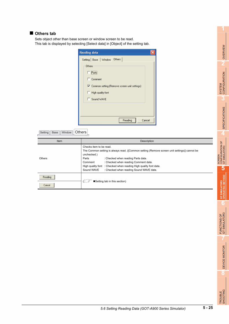
1
OV
ER
VIE
W
2
SY
ST
EM
C
ON
FIG
UR
AT
ION
3
SP
EC
IFIC
AT
ION
S
4
SC
RE
EN
C
ON
FIG
UR
AT
ION
OF
G
T S
IMU
LAT
OR
3
5
GT
SIM
UL
AT
OR
3 O
PE
RA
TIN
G M
ET
HO
D
6
FU
NC
TIO
NS
OF
G
T S
IMU
LA
TO
R3
7
DE
VIC
E M
ON
ITO
R
8
TR
OU
BLE
SH
OO
TIN
G
Others tabSets object other than base screen or window screen to be read.This tab is displayed by selecting [Select data] in [Object] of the setting tab.
Item Description
Others
Checks item to be read.
The Common setting is always read. ([Common setting (Remove screen unit settings)] cannot be
unchecked.)
Parts : Checked when reading Parts data.
Comment : Checked when reading Comment data.
High quality font : Checked when reading High quality font data.
Sound WAVE : Checked when reading Sound WAVE data.
( Setting tab in this section)
OthersSetting Base Window
5.6 Setting Reading Data (GOT-A900 Series Simulator) 5 - 25

5.7 Simulating Operation
On GT Simulator3, touching the touch keys is performed by pressing the mouse button.As the input range of the touch key is narrower than that of the GOT, confirm the input with the buzzer sound after inputting.
5.8 Exiting from GT Simulator3
This section describes how to exit from GT Simulator3.
1. When using the Device Monitor, exit it. 7.4 Device Monitor Operation Method
2. Perform either of the following operations.
• Click (Close).• Select [Project] [Exit] from the menu.• Select [Simulate] [Exit] from the menu.
• Click the on the tool bar.
• Right-click the mouse and select [Exit]
3. GT Simulator3 is exited.
5 - 26 5.7 Simulating Operation
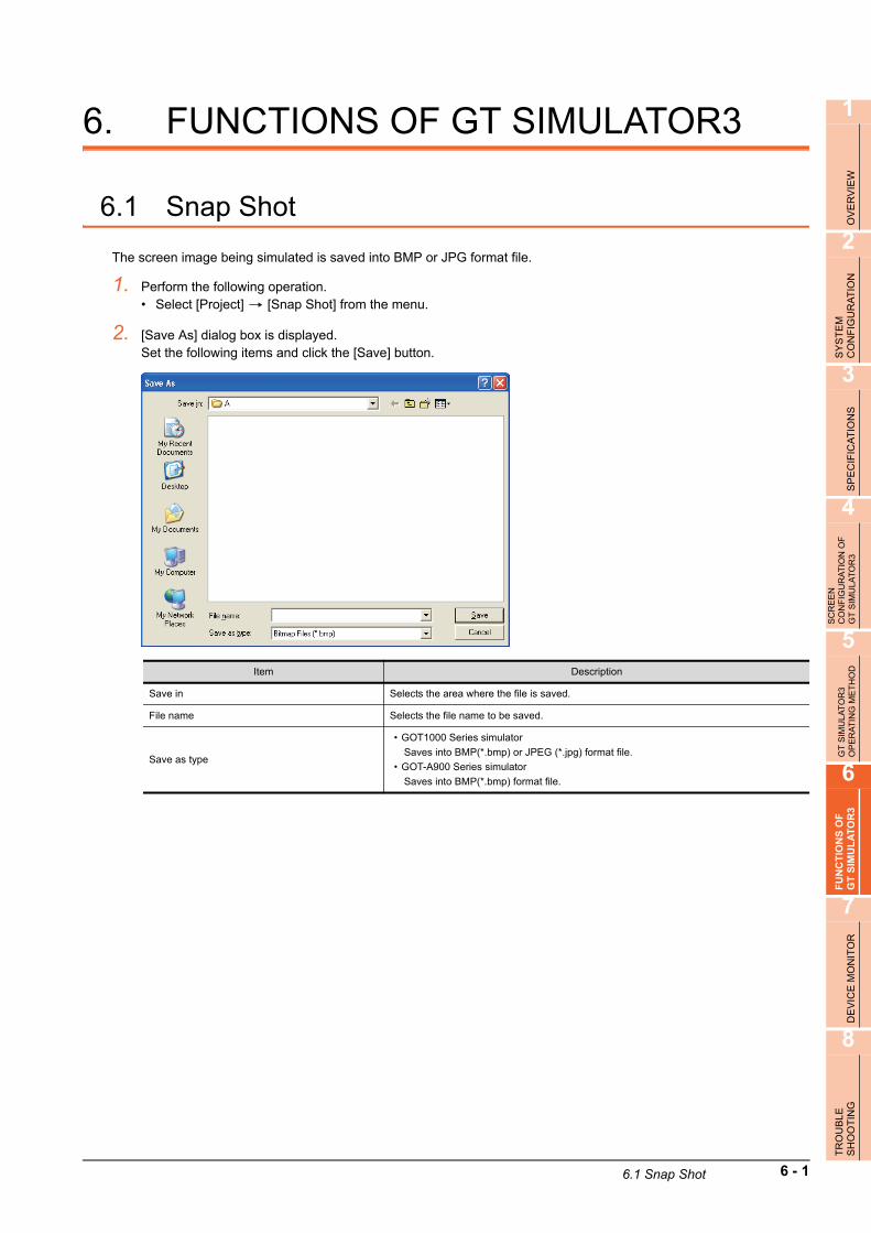
1
OV
ER
VIE
W
2
SY
ST
EM
C
ON
FIG
UR
AT
ION
3
SP
EC
IFIC
AT
ION
S
4
SC
RE
EN
C
ON
FIG
UR
AT
ION
OF
G
T S
IMU
LAT
OR
3
5
GT
SIM
ULA
TO
R3
OP
ER
AT
ING
ME
TH
OD
6
FU
NC
TIO
NS
OF
G
T S
IMU
LA
TO
R3
7
DE
VIC
E M
ON
ITO
R
8
TR
OU
BLE
SH
OO
TIN
G
6. FUNCTIONS OF GT SIMULATOR3
6.1 Snap Shot
The screen image being simulated is saved into BMP or JPG format file.
1. Perform the following operation.• Select [Project] [Snap Shot] from the menu.
2. [Save As] dialog box is displayed.Set the following items and click the [Save] button.
Item Description
Save in Selects the area where the file is saved.
File name Selects the file name to be saved.
Save as type
• GOT1000 Series simulator
Saves into BMP(*.bmp) or JPEG (*.jpg) format file.
• GOT-A900 Series simulator
Saves into BMP(*.bmp) format file.
6.1 Snap Shot 6 - 1

6.2 Print
The screen image being simulated is printed to a printer.
6.2.1 Printing
1. Perform the following operation.• Select [Project] [Print] from the menu.
2. Print dialog box of Windows is displayed.Click the [OK] button to start printing.
6 - 2 6.2 Print

1
OV
ER
VIE
W
2
SY
ST
EM
C
ON
FIG
UR
AT
ION
3
SP
EC
IFIC
AT
ION
S
4
SC
RE
EN
C
ON
FIG
UR
AT
ION
OF
G
T S
IMU
LAT
OR
3
5
GT
SIM
ULA
TO
R3
OP
ER
AT
ING
ME
TH
OD
6
FU
NC
TIO
NS
OF
G
T S
IMU
LA
TO
R3
7
DE
VIC
E M
ON
ITO
R
8
TR
OU
BLE
SH
OO
TIN
G
6.2.2 Performing print preview
1. Perform the following operation.• Select [Project] [Print Preview] from the menu.
2. Print Preview is displayed.
6.2 Print 6 - 3

6.2.3 Performing page setup
1. Perform the following operation.• Select [Project] [Page Setup] from the menu.
2. [Page Setup] dialog box is displayed.Set the following items and click the [OK] button.
6.2.4 Performing print setup
1. Perform the following operation.• Select [Project] [Print Setup] from the menu.
2. Print dialog box of Windows is displayed.Set printer settings (selection of printer, paper size and Printing direction).Click the [OK] button to start printing.
Item Description
Margin Set the margins on a page to be printed.
Reverse screen image Select this item to reverse the colors of screen image when printing.
Reverse Mode
Set the reverse mode for screen image.
• Color : Reverse all the colors of screen image to be printed.
• Black and White : Reverse the black and white colors of screen image to be printed.
6 - 4 6.2 Print

1
OV
ER
VIE
W
2
SY
ST
EM
C
ON
FIG
UR
AT
ION
3
SP
EC
IFIC
AT
ION
S
4
SC
RE
EN
C
ON
FIG
UR
AT
ION
OF
G
T S
IMU
LAT
OR
3
5
GT
SIM
ULA
TO
R3
OP
ER
AT
ING
ME
TH
OD
6
FU
NC
TIO
NS
OF
G
T S
IMU
LA
TO
R3
7
DE
VIC
E M
ON
ITO
R
8
TR
OU
BLE
SH
OO
TIN
G
6.3 Property
Project title, Project ID and Data Size of project data being simulated are displayed.
1. Perform the following operation.• Select [Project] [Property] from the menu.
2. [Properties] dialog box is displayed.
POINTPOINTPOINT
When property dialog box is displayed before starting simulation.
When property dialog box is displayed before starting simulation, project title, project ID and data size of project data simulated previously are displayed.(If project data has not been loaded, project title, project ID and data size are not displayed.)
Item Description
Project Title Project title is displayed.
Project ID Project ID is displayed.
Data Size Data size of project data is displayed.
6.3 Property 6 - 5

6.4 System Alarm
System alarm is displayed.If system alarm is not set to project data, it can be confirmed with this dialog box.
1. Perform the following operation.• Select [Tool] [System alarm] from the menu.
2. [System Alarm] dialog box is displayed.
*1 Refer to the following manual for list of system alarm.
User's Manual for the GOT used
POINTPOINTPOINT
About system alarm to be displayed.
• Only the error detected by GOT is displayed on the system alarm dialog box.Set the system alarm to project data for confirming error of PLC CPU and network.
• Error messages are displayed in English.To display them in other languages, set system alarm in the project data.
Item Description
System alarm Error contents are displayed.
Displayed error message is cleared.
However, it is redisplayed when the error keeps occuring.
6 - 6 6.4 System Alarm

1
OV
ER
VIE
W
2
SY
ST
EM
C
ON
FIG
UR
AT
ION
3
SP
EC
IFIC
AT
ION
S
4
SC
RE
EN
C
ON
FIG
UR
AT
ION
OF
G
T S
IMU
LAT
OR
3
5
GT
SIM
ULA
TO
R3
OP
ER
AT
ING
ME
TH
OD
6
FU
NC
TIO
NS
OF
G
T S
IMU
LA
TO
R3
7
DE
VIC
E M
ON
ITO
R
8
TR
OU
BLE
SH
OO
TIN
G
6.5 Script Error
Script error information is displayed.
1. Perform the following operation.• Select [Tool] [Script Error] menu.
2. Script error information dialog box is displayed.
*1 Refer to the following manual for script function.
GT Designer3 Version1 Screen Design Manual (Functions)
Item Description
Script No. *1 Script No. where error occurs is displayed.
Error No. Error code of occurring error is displayed.
Error Message Error contents are displayed.
Script is executed again.
Displayed error message is cleared.
However, it is redisplayed when the error keeps occuring.
6.5 Script Error 6 - 7

6.6 Object Script Error
Object script error information is displayed.
1. Perform the following operation.• Select [Tool] [Object script Error] from the menu.
2. [Object Script Error Information] dialog box is displayed.
*1 Refer to the following manual for object script function.
GT Designer3 Version1 Screen Design Manual (Functions)
Item Description
Script user ID *1 User ID of the object script where error occurs is displayed.
Error No. Error code of occurring error is displayed.
Error Message Error contents are displayed.
Object script is executed again.
Displayed error message is cleared.
However, it is redisplayed when the error keeps occuring.
6 - 8 6.6 Object Script Error

1
OV
ER
VIE
W
2
SY
ST
EM
C
ON
FIG
UR
AT
ION
3
SP
EC
IFIC
AT
ION
S
4
SC
RE
EN
C
ON
FIG
UR
AT
ION
OF
G
T S
IMU
LAT
OR
3
5
GT
SIM
ULA
TO
R3
OP
ER
AT
ING
ME
TH
OD
6
FU
NC
TIO
NS
OF
G
T S
IMU
LA
TO
R3
7
DE
VIC
E M
ON
ITO
R
8
TR
OU
BLE
SH
OO
TIN
G
6.7 Full Screen Mode Function (GT16**-X, GT15**-X only)
When selecting GT16**-X, GT15**-X (Resolution: 1024 768 dots), the GT Simulator3 screen can be displayed in full screen mode on a PC display.When the resolution of the PC display is 1024 768 dots, hiding the parts including menu bar with this function is recommended.When not using this function, the top/bottom/left/right side on the display are hidden.
Executing full screen display
1. Perform either of the following operations.• Alt + F9• Right-click the mouse and select [Full Screen Mode] from the menu.
2. The full screen mode dialog box is displayed.Clicking the [OK] button displays the GT Simulator3 in full screen mode.
Canceling full screen mode
1. Perform either of the following operations.• Alt + F9• Right-click the mouse and select [Full Screen Mode] from the menu.
2. Full screen mode cancel dialog box is displayed.Clicking the [OK] button cancels the full screen mode.
POINTPOINTPOINT
• "In full screen mode, [Open], [Start], [Stop] and [Option] can be operated.When operating other than the above, cancel the full screen mode. (Refer to procedure 2. for how to cancel full screen mode.)"
• When full screen mode has been set before executing simulation, the project data of other than GT16**-X,
GT15**-X (Resolution: 1024 768 dots) cannot be opened.• When using full screen mode under the environment that the resolution of the PC display is greater than
1024 768 dots, GT Simulator3 display position is fixed on the upper-left. (The display position cannot be changed.)
6.7 Full Screen Mode Function (GT16**-X, GT15**-X only) 6 - 9

6 - 10 6.7 Full Screen Mode Function (GT16**-X, GT15**-X only)

1
OV
ER
VIE
W
2
SY
ST
EM
C
ON
FIG
UR
AT
ION
3
SP
EC
IFIC
AT
ION
S
4
SC
RE
EN
C
ON
FIG
UR
AT
ION
OF
G
T S
IMU
LAT
OR
3
5
GT
SIM
ULA
TO
R3
OP
ER
AT
ING
ME
TH
OD
6
FU
NC
TIO
NS
OF
G
T S
IMU
LA
TO
R3
7
DE
VIC
E M
ON
ITO
R
8
TR
OU
BLE
SH
OO
TIN
G
7. DEVICE MONITOR
7.1 Overview
The device values of project data simulated on GT Simulator3 can be monitored or tested by Device Monitor function.The dubugging can be performed efficiently since the display can be checked on GT Simulator3 by this function.
7.1 Overview 7 - 1

7.2 Precautions
POINTPOINTPOINT
Instructions for use of GT Simulator3
Refer to the following for the instructions for use of GT Simulator3.
3.3 Precautions
(1) Starting multiple device monitorsMultiple device monitors can not be start up at the same time.
(2) When referring the device value GT Simulator3 does not show on the screenThe Device Monitor shows the device list by the screen.For the device value GT Simulator3 does not show on the screen, set the device with [Free Registration screen] of GT Simulator3 and refer the device value.
7.5.3 Registering/Deleting device (Free Registration screen)
(3) When using screen call functionThe device set on the called function will not be shown when screen call function is used.For the device value on the called function, set the device on [Free Registration screen] of GT Simulator3 and refer the device value.
7.5.3 Registering/Deleting device (Free Registration screen)
(4) Switching station No. at the direct CPU connectionThe monitored device cannot be switched by using switching station No. at the direct CPU connection.For the monitored device, set the device with [Free Registration screen] and refer the device value.
7.5.3 Registering/Deleting device (Free Registration screen)
(5) Connection to GX SimulatorIn regard to the devices out of the GX Simulator's support, the values are not shown.
(6) When simulating the project data of which PC type is third party PLC(Connection to GX Simulator)In regard to the devices out of the simulation available range, the values are not shown.Refer to the following for the device ranges that can be simulated.
3.4 Device Ranges that Can Be Simulated
(7) When using object scriptsThe temporary device area (TMP) for object scripts cannot be confirmed with the Device Monitor (GT Simulator3).
7 - 2 7.2 Precautions

1
OV
ER
VIE
W
2
SY
ST
EM
C
ON
FIG
UR
AT
ION
3
SP
EC
IFIC
AT
ION
S
4
SC
RE
EN
C
ON
FIG
UR
AT
ION
OF
G
T S
IMU
LAT
OR
3
5
GT
SIM
ULA
TO
R3
OP
ER
AT
ING
ME
TH
OD
6
FU
NC
TIO
NS
OF
G
T S
IMU
LA
TO
R3
7
DE
VIC
E M
ON
ITO
R
8
TR
OU
BLE
SH
OO
TIN
G
7.3 Screen Configuration of Device Monitor
7.3.1 Screen configuration and various Tools
This section describes the configuration and various tools of device monitor.
Device Monitor screen
Status Bar
Title bar
Tool barMenu Bar
7.3.3 Tool Bar
7.3.4 Device Monitor
screen
7.3.5 Status Bar
7.3.2 Menu Bar
7.3 Screen Configuration of Device Monitor 7 - 3

7.3.2 Menu Bar
The commands assigned to the menu bar are described below.
File
File menu includes the function to exit the Device Monitor.
• 7.4 Device Monitor Operation Method
Edit
Edit menu includes the functions to register or delete devices in [Free
Registration screen].
(This menu becomes available when [Free Registration screen] is
selected on the Device Monitor.)
• 7.3.4 Device Monitor screen
• 7.4 Device Monitor Operation Method
View
View menu includes the functions such as starting/stopping monitoring
and setting the Device Monitor.
• 7.3.3 Tool Bar
• 7.3.5 Status Bar
• 7.4 Device Monitor Operation Method
Window
Window menu includes the functions such as aligning the Device
Monitor screens and selecting display screens.
• 7.3.4 Device Monitor screen
• 7.4 Device Monitor Operation Method
7 - 4 7.3 Screen Configuration of Device Monitor

1
OV
ER
VIE
W
2
SY
ST
EM
C
ON
FIG
UR
AT
ION
3
SP
EC
IFIC
AT
ION
S
4
SC
RE
EN
C
ON
FIG
UR
AT
ION
OF
G
T S
IMU
LAT
OR
3
5
GT
SIM
ULA
TO
R3
OP
ER
AT
ING
ME
TH
OD
6
FU
NC
TIO
NS
OF
G
T S
IMU
LA
TO
R3
7
DE
VIC
E M
ON
ITO
R
8
TR
OU
BLE
SH
OO
TIN
G
7.3.3 Tool Bar
This section describes the tool bar.
Before monitoring
While monitoring
Name Description
Start Executes device monitoring.
Change the display
format of the
device value.
Choose the device value display format in the list box.
( 7.3.4 (1) Display of [Value])
With/Without a sign
Make selection when handling the device value as signed binary value.
The [Changes of display of device value] can only be selected when [Decimal] is
chosen.
( 7.3.4 (1) Display of [Value])
Name Description
Stop Stops device monitoring.
Change the display
format of the
device value.
Choose the device value display format in the list box.
( 7.3.4 (1) Display of [Value])
With/Without a sign
Make selection when handling the device value as signed binary value.
The [Changes of display of device value] can only be selected when [Decimal] is
chosen.
( 7.3.4 (1) Display of [Value])
7.3 Screen Configuration of Device Monitor 7 - 5

7.3.4 Device Monitor screen
This section describes the Device Monitor screen.
Devise Monitor typesThe Device Monitor is available in the following four types which show the different contents and items in the screen.
POINTPOINTPOINT
Synchronization for the Monitor Mode of Device Monitor and GT Simulator3
The Monitor Mode of Device Monitor and GT Simulator3 can be disabled from synchronizing.For details, refer to the following.
7.6.1 Monitor Mode tab
(Base Screen) (Window Screen)
(Common screen) (Free Registration screen)
Screen Description
Base ScreenConfirms/Tests the device used on the Base Screen.
Device for each Base Screen is displayed.
Window ScreenConfirms/Tests the device used on the Overlap window (1, 2, 3, 4, 5) or the Superimpose window (1, 2).
Device for each Window Screen is displayed.
Common screen Confirms/Tests the contents set with the common setting of GT Designer3.
Free Registration screen
Registers any device and confirms/tests the device value.
Since all devices (including GOT's internal devices) can be registered, devices not set in the data can be
registered and confirmed/tested.
Refer to the following for device registration.
7.5.3 Registering/Deleting device (Free Registration screen)
7 - 6 7.3 Screen Configuration of Device Monitor

1
OV
ER
VIE
W
2
SY
ST
EM
C
ON
FIG
UR
AT
ION
3
SP
EC
IFIC
AT
ION
S
4
SC
RE
EN
C
ON
FIG
UR
AT
ION
OF
G
T S
IMU
LAT
OR
3
5
GT
SIM
ULA
TO
R3
OP
ER
AT
ING
ME
TH
OD
6
FU
NC
TIO
NS
OF
G
T S
IMU
LA
TO
R3
7
DE
VIC
E M
ON
ITO
R
8
TR
OU
BLE
SH
OO
TIN
G
Items displayed on the Device MonitorThe items displayed on the Device Monitor will be described below.
(1) Display of [Value]Display of [Value] is shown in the following table depending on the selection of [Changes of display of deivce value] and [With/Without a sign] on the tool bar.
Number Item Description
1) Object Shows the preset object names.
2) Position Displays the displayed object positions (coordinates).
3) Device Kind Shows the device types.
4) DeviceShows the devices set for the objects.
The devices are represented as on GT Designer3.
5) Type
Shows the used device types.
Bit : When bit device is used
Word (16) : When word device (16bit) is used
Word (32) : When word device (32bit) is used
6) Value Shows the device values. ( (1) Display of [Value] in this section)
7) Change Changes the device values. ( 7.5.2 Testing device value)
8) Function Shows the Common screen name with GT Designer3.
Setting of [Changes of display of
deivce value] and [With/Without a
sign]
Display of [Value]
When [Type] is [Bit] When [Type] is [Word (16)] When [Type] is [Word (32)]
Binary
0, 1(1 digit)
0000 0000
to 1111 1111(16 digits)
0000 0000
to 1111 1111(32 digits)
Octal 0 to 177777 0 to 37777777777
DecimalSigned -32768 to 32767
-2147483648
to 2147483647
Unsigned 0 to 65535 0 to 4294967295
Hexadecimal 0 to FFFF 0 to FFFFFFFF
1) 2) 3) 4) 5) 6) 7)
8)
7.3 Screen Configuration of Device Monitor 7 - 7

7.3.5 Status Bar
The status bar will be described below.
Number Description
1) Shows the descriptions of button and menu at the mouse cursor.
2)
Shows the PLC CPU type currently connected.
With the direct CPU connection : "CPU: <Connected PLC CPU type>"
With GX Simulator : "GX Simulator: <Connected PLC CPU type>"
3) Shows the setting contents of Monitor Mode. ( 7.6 Setting Display)
4)
Indicates the monitor status with the lamps.
Lamps flickering : Monitor is in progress.
Both lamps are lit green : Monitor is at a stop.
1) 2) 3) 4)
7 - 8 7.3 Screen Configuration of Device Monitor

1
OV
ER
VIE
W
2
SY
ST
EM
C
ON
FIG
UR
AT
ION
3
SP
EC
IFIC
AT
ION
S
4
SC
RE
EN
C
ON
FIG
UR
AT
ION
OF
G
T S
IMU
LAT
OR
3
5
GT
SIM
ULA
TO
R3
OP
ER
AT
ING
ME
TH
OD
6
FU
NC
TIO
NS
OF
G
T S
IMU
LA
TO
R3
7
DE
VIC
E M
ON
ITO
R
8
TR
OU
BLE
SH
OO
TIN
G
7.4 Device Monitor Operation Method
The device monitor operation method will be shown below.
Start
Exit
Start the Device Monitor.
Perform debugging on the Device Monitor.
Stop and restart the monitor.
Exit from the Device Monitor.
When interrupting the
monitor only
7.4.1 Starting Device Monitor
7.5 Device Monitor Functions
7.4.2 Stopping and restarting the monitor
7.4.3 Exit Device Monitor
7.4 Device Monitor Operation Method 7 - 9

7.4.1 Starting Device Monitor
1. The Simulation in GT Simulator3 do either of the following operations.
• Click (Start of Device Monitor) of GT Simulator3.• Select [Tool] [Start of Device Monitor] from the menu of GT Simulator3.
2. The Device Monitor starts, and then executes monitoring.
POINTPOINTPOINT
Start of Device Monitor
Start the Device Monitor while simulating on GT Simulator3.The Device Monitor cannot be started before executing or after stopping of the simulation on GT Simulator3.
7 - 10 7.4 Device Monitor Operation Method

1
OV
ER
VIE
W
2
SY
ST
EM
C
ON
FIG
UR
AT
ION
3
SP
EC
IFIC
AT
ION
S
4
SC
RE
EN
C
ON
FIG
UR
AT
ION
OF
G
T S
IMU
LAT
OR
3
5
GT
SIM
ULA
TO
R3
OP
ER
AT
ING
ME
TH
OD
6
FU
NC
TIO
NS
OF
G
T S
IMU
LA
TO
R3
7
DE
VIC
E M
ON
ITO
R
8
TR
OU
BLE
SH
OO
TIN
G
7.4.2 Stopping and restarting the monitor
1. Choose either of the following operations to stop the monitor.
• Click (Stop) of the Device Monitor.• Select [View] [Monitor] [Stop] from the menu of the Device Monitor.
2. Choose either of the following operations to restart the monitor after stopping.
• Click (Start) of the Device Monitor.• Select [View] [Monitor] [Start] from the menu of the Device Monitor.
POINTPOINTPOINT
About Stop monitor /Exit devcie monitor
If monitor is stopped, the Device Monitor is not exited.Refer to the following manual to exit device monitor
7.4.3 Exit Device Monitor
7.4.3 Exit Device Monitor
1. Exit Device Monitor with any of the following operations.• Select [File] [Exit Device Monitor] from the menu of the Device Monitor.
• Click on the title bar of the Device Monitor.
• Click (Start/Exit of Device Monitor) of GT Simulator3.• Select [Tool] [Exit Device Monitor] from the menu of GT Simulator3.
POINTPOINTPOINT
Exiting and Message of GT Simulator3/Device Monitor
Exit from GT Simulator after exiting from the Device Monitor.If exiting GT Simulator while monitoring with the Device Monitor, the following message may be displayed under other screens.
If having exited GT Simulator while monitoring with the Device Monitor, operate after carrying on a process such as moving the other screens.
7.4 Device Monitor Operation Method 7 - 11

7.5 Device Monitor Functions
This section describes the device monitoring functions.
7.5.1 Sorting the data
This function allows the data displayed in the Device Monitor to be arranged in ascending or descending order of character code.By default, the column data on the left of the corresponding screen are displayed in ascending or descending order of character code.
1. Clicking the title of the corresponding column rearranges the column data in ascending or descending order of character codes.
POINTPOINTPOINT
(1) The sorting order of [Object][Object] can be set the sorting order by users.For details, refer to the following.
7.6 Setting Display
(2) The sorting order of [Change][Change] cannot be rearranged the sorting order.Rearrange with the other column data.
Click this part.
7 - 12 7.5 Device Monitor Functions

1
OV
ER
VIE
W
2
SY
ST
EM
C
ON
FIG
UR
AT
ION
3
SP
EC
IFIC
AT
ION
S
4
SC
RE
EN
C
ON
FIG
UR
AT
ION
OF
G
T S
IMU
LAT
OR
3
5
GT
SIM
ULA
TO
R3
OP
ER
AT
ING
ME
TH
OD
6
FU
NC
TIO
NS
OF
G
T S
IMU
LA
TO
R3
7
DE
VIC
E M
ON
ITO
R
8
TR
OU
BLE
SH
OO
TIN
G
7.5.2 Testing device value
The device value can be tested with this function.You can check how the indication of the tested device value changes on GT Simulator3.
Values that can be testedThe range of values that can be tested is the same as the display range.For details, refer to the following.
Section 7.3.4 (1) Display of [Value]
Testing methodHow to test a device value is given below.
(1) When testing a bit device with the mouse
1. By clicking [ON] or [OFF] with the mouse, the device value is reflected to [Value] and [Change].
(2) When testing a bit device with the keyboard.
1. By choosing [Value] and entering 0 or 1 with the personal computer keyboard, the device value is reflected to [Value] and [Change].
(3) When testing a word device with the mouse
1. Device value input window
2. By setting the device value with the to button and pressing the button, the device value is reflected to [Value] and [Change]. (You can also input the device value directly.)
(4) When editing a word device with the keyboard.
1. By choosing and directly editing [Value], the device value is reflected to [Value] and [Change].
Click this
part.
Click this
part.
0 F BK CL ENT
7.5 Device Monitor Functions 7 - 13

7.5.3 Registering/Deleting device (Free Registration screen)
You can register any device on the Free Registration screen and test the device.By registering a device not set in the project data and testing the value, you can make an operation check after the change.
How to register a device
1. Choose either of the following operations.• Select [Edit] [Regist Device] from the menu of the Device Monitor.• Click the [Regist] button of [Free Registration screen]
2. The Regist Device dialog box appears.By setting the following items and clicking the [OK] button, the device is registered.
POINTPOINTPOINT
(1) Display order of the devicesThe devices are displayed from top to bottom in registration order.
(2) Operation for discarding the registered contentsIf the [PLC Type] of the simulated project data is changed, the registered contents will be discarded.
How to delete the devices
1. Display the device to be deleted on [Free Registration screen].
2. By choosing either of the following operations, the device is deleted.• Select [Edit] [Delete Device] from the menu of the Device Monitor.• Click the [Delete] button of [Free Registration screen]
How to delete all devices
1. Display the [Free Registration screen].
2. By choosing either of the following operations, all devices are deleted.• Select [Edit] [Delete All Device] from the menu of the Device Monitor.• Click the [Delete All] button of [Free Registration screen].
Item Description
Device type Selects the Device type.
Sets the device.
For setting the device, refer to the following.
GT Designer3 Version1 Screen Design Manual (Fundamentals)
Points Sets the point of the device to be registered from the device set with the [Device] button consecutively.
7 - 14 7.5 Device Monitor Functions

1
OV
ER
VIE
W
2
SY
ST
EM
C
ON
FIG
UR
AT
ION
3
SP
EC
IFIC
AT
ION
S
4
SC
RE
EN
C
ON
FIG
UR
AT
ION
OF
G
T S
IMU
LAT
OR
3
5
GT
SIM
ULA
TO
R3
OP
ER
AT
ING
ME
TH
OD
6
FU
NC
TIO
NS
OF
G
T S
IMU
LA
TO
R3
7
DE
VIC
E M
ON
ITO
R
8
TR
OU
BLE
SH
OO
TIN
G
7.5.4 Displaying screens with cascade/tile
You can display all screens with cascade/tile.
1. Select [Window] [Cascade] / [Horizontal] / [Vertical] from the menu of the Device Monitor.
2. The screens are displayed as follows.• When selecting the [Cascade] from the menu
• When selecting the [Horizontal] from the menu
• When selecting the [Vertical] from the menu
7.5 Device Monitor Functions 7 - 15

7.5.5 Changing Device Monitor screen
When changing the Device Monitor screen
1. Select the screen to be displayed on the Device Monitor with the [Window] from the menu.
When changing the Screen No. of the screen to be displayed
1. If displaying the Base Screen, the selection for the Screen No. of the screen to be displayed is available with [Moni No.].If displaying the Window Screen, the selection for the Screen No. of the screen to be displayed and Non-Display setting for the screen is available with [Moni No.] .
7 - 16 7.5 Device Monitor Functions

1
OV
ER
VIE
W
2
SY
ST
EM
C
ON
FIG
UR
AT
ION
3
SP
EC
IFIC
AT
ION
S
4
SC
RE
EN
C
ON
FIG
UR
AT
ION
OF
G
T S
IMU
LAT
OR
3
5
GT
SIM
ULA
TO
R3
OP
ER
AT
ING
ME
TH
OD
6
FU
NC
TIO
NS
OF
G
T S
IMU
LA
TO
R3
7
DE
VIC
E M
ON
ITO
R
8
TR
OU
BLE
SH
OO
TIN
G
7.6 Setting Display
The display of the Device Monitor can be customized.
1. Perform the following operation.• Select [View] [Configure] from the menu of the Device Monitor.
2. The Setting dialog box is displayed.Set each item and click the [OK] button.For details of the Setting dialog box, refer to the following.
7.6.1 Setting items
7.6.1 Setting items
Object Sort Setting tabYou can set the display order of the [Object] column data shown on base or window screen.
No. Item Description
1) Object item Choose the object item you want to move.
2) up, down Used to move the object selected in the object item.
3) Default Used to select the standard (default) setting of the object item display order.
Object
1) 2)
3)
Object Sort Setting Col Setting Monitor Mode GOT Internal Device Setting
7.6 Setting Display 7 - 17

Col Setting tabYou can set the displayed column data order on the Base, Window, Common or Free Registration screen.
No. Item Description
1) Select Window Choose the Device Monitor screen where you want to change the displayed column data order.
2) Displayed column item Choose the displayed column item you want to move.
3) up, down Used to move the object selected in the displayed column item.
4) Default Used to select the standard (default) setting of the displayed column item display order.
Displayed column
2) 3)
4)
1)
Object Sort Setting Col Setting Monitor Mode GOT Internal Device Setting
7 - 18 7.6 Setting Display

1
OV
ER
VIE
W
2
SY
ST
EM
C
ON
FIG
UR
AT
ION
3
SP
EC
IFIC
AT
ION
S
4
SC
RE
EN
C
ON
FIG
UR
AT
ION
OF
G
T S
IMU
LAT
OR
3
5
GT
SIM
ULA
TO
R3
OP
ER
AT
ING
ME
TH
OD
6
FU
NC
TIO
NS
OF
G
T S
IMU
LA
TO
R3
7
DE
VIC
E M
ON
ITO
R
8
TR
OU
BLE
SH
OO
TIN
G
Monitor Mode tabYou can set the Monitor Mode pattern for synchronizing/not synchronizing the Device Monitor and GT Simulator3 screen (Base Screen, Window Screen).
POINTPOINTPOINT
Testing of device value
If you test device value without regarding of this setting, any changes are reflected on the Device Monitor and GT Simulator3.When you do not want to reflect device value changes, stop the monitor and then test the device value.
7.4 Device Monitor Operation Method
Item Description
Monitor Mode Setting
Choose the screen switching pattern.
• Device Monitor <-> GT Simulator3
Changing either of the Device Monitor screen and GT Simulator3 screen also changes the other.
• Device Monitor -> GT Simulator3
Changing the Device Monitor screen changes the GT Simulator3 screen.
If you change the GT Simulator3 screen, the Device Monitor does not change.
• GT Simulator3 -> Device Monitor
Changing the GT Simulator3 screen changes the Device Monitor screen.
If you change the Device Monitor screen, the GT Simulator3 screen does not change.
• Device Monitor -X- GT Simulator3
Changing either of the Device Monitor screen and GT Simulator3 screen does not change the other.
Object Sort Setting Col Setting Monitor Mode GOT Internal Device Setting
7.6 Setting Display 7 - 19

GOT internal Device Setting tabWhen exiting from GT Simulator3, save the internal device (GD, GB, GS) states and set Display/Non-Display of the states at the previous exit when monitoring next time.
Item Description
Keep ValuesCheck this check box to save the internal device values at monitor stop or end, and display the saved internal
device values at the time of next monitoring.
Object Sort Setting Col Setting Monitor Mode GOT Internal Device Setting
7 - 20 7.6 Setting Display

1
OV
ER
VIE
W
2
SY
ST
EM
C
ON
FIG
UR
AT
ION
3
SP
EC
IFIC
AT
ION
S
4
SC
RE
EN
C
ON
FIG
UR
AT
ION
OF
G
T S
IMU
LAT
OR
3
5
GT
SIM
ULA
TO
R3
OP
ER
AT
ING
ME
TH
OD
6
FU
NC
TIO
NS
OF
G
T S
IMU
LA
TO
R3
7
DE
VIC
E M
ON
ITO
R
8
TR
OU
BL
ES
HO
OT
ING
8. TROUBLESHOOTING
8.1 Troubleshooting for File Save Problems
8.2 Error Message (GOT1000 series simulator)
The following table indicates the error messages occurred in GOT1000 series simulator themselves, the Descriptions and resolutions.
Error messages displayed when GT Simulator3 is used.
(Continue to the following page)
Problem Definition and Cause Corrective action
No files are output when the hard copy command
is executed from the monitor screen of the GT
Simulator3.
The file cannot be saved due to problems with
the output destination disk.
• Confirm that the folder that is designated as a
virtual drive does exist.
• Check the access right for the folder that is
designated as a virtual drive.
• Confirm that there is enough free space in the
folder that is designated as a virtual drive.
The file cannot be saved, since file number
external control device value is set to a value
outside of the range 1 to 9999.
• Confirm that the file number external control
device value is set to a value in the range 1 to
9999.
Error message Definition and cause Corrective action
Adobe Reader is not installed correctly.
Please install Adobe Reader.
• Adobe Reader is not installed.
• AdobeReader is not installed correctly.After uninstalling AdobeReader, reinstall it.
Easysocket is not installed. Perhaps GT Simulator3 is not installed correctly. After uninstalling GT Simulator3, reinstall it.
'GT Simulator3' is not correctly installed.Can not find the Windowsregistry for GT
Simulator3.After uninstalling GT Simulator3, reinstall it.
PLC type of 'GT Simulator3' setting and 'GX
Developer' setting is different.
Please confirm the content of 'GX Developer'
setting or change the PLC type of option setting.
These two CPU type settings are different.Change the CPU type in the GX Developer
project.
'GT Simulator3' cannot work, since language
version for 'GT Simulator3' is different from one
for 'GX Simulator'.
GT Simulator3 doesn't work, since the language
version of GT Simulator3 is different from that of
GX Simulator.
Install the same language version GX Simulator
and GT Simulator3 .
Installation path of 'GT Simulator3' cannot be
acquired.Perhaps GT Simulator3 is not installed correctly. After uninstalling GT Simulator3, reinstall it.
This operating environment is unapplicable for
'GT Simulator3'.
Access could not be made to the file necessary
to operate GT Simulator3.
• Check whether the user logs in to Windows
XP, Windows Vista, or Windows 7 as the
user with the administrator authority (for the
computer management).
• Check whether the fast user switching function
or the remote desktop function of Windows
XP, Windows Vista, or Windows 7 is in use.
• GT Simulator3 was not closed propety.
• Illegal process is running.Resart GT Simulator3 after reboot the computer.
Please do logoff/the termination of Windows after
ending 'GT Simulator3'.
Close GT Simulator3 before log out or shut down
the Windows.
Close GT Simulator3 before log out or shut down
the Windows.
8.1 Troubleshooting for File Save Problems 8 - 1

(Continued to next page)
Error message Definition and cause Corrective action
Project Information of 'GX Developer' was not be
acquired.
GPPW.GPS or GPPW.GPJ is not found.
Set a wrong GX Developer project.In Option setting, set the project of GX Developer
again.
Project path of 'GX Developer' cannot acquired.
<cause>
• 'GT Simulator3' is not correctly installed.
• Unsupport PLC type is selected.
• Registry is destroyed.
• Registry information on the project path of GX
Developer was corrupted.
• Unsupport CPU type was specified.
In Option dialog box, set the project of GX
Developer again.
GT Simulator3 is not installed correctly. After uninstalling GT Simulator3, reinstall it.
An illegal project of 'GX Developer' is selected.The project specified in [GX Developer Project] of
Option dialog box does not exist.
Check whether the specified GX Developer
project exists.
'GX Simulator' is not installed.• GX Simulator is not installed.
• GX Simulator is not installed correctly.Install GX Simulator.
An illegal project of 'GX Developer' is selected.
(SFC program)
Project cannot be forwarded to 'GX Simulator'.
Specified an SFC type GX Developer project.In Option setting, set the project of GX Developer
again.
Failed in the start of 'GX Simulator'.
<ES: ****>
************ error
(2 different messages in all)
GX Simulator may be not installed correctly.
• After uninstalling GT Simulator, reinstall it.
• Reinstall the update versions of GT
Simulator3, GX Simulator and/or GX
Developer.
Insufficient memory to starting 'GX Simulator'.Not enough Dynamic memory to start up GT
Simulator3.
Secure memory space.
• Close unnecessary applications.
• Check free hard disk space.
Failed in the initialization of 'GX Simulator'.
<ES: ****>
************
(32 different messages in all)
GX Simulator may be not installed correctly. After uninstalling GT Simulator, reinstall it.
• GT Simulator3, GX Simulator or GX Developer
was not closed properly.
• Illegal process is running.
• Restart GT Simulator3.
• After restarting the personal computer, restart
GT Simulator3.
• Reinstall the update versions of GT
Simulator3, GX Simulator and/or GX
Developer.
Failed in the start of Shared memory server.
<ES: ****>
************ error
(2 different messages in all)
• GT Simulator3, GX Simulator or GX Developer
was not closed properly.
• Illegal process is running.
• After restarting the personal computer, restart
GT Simulator3.
• Reinstall the update versions of GT
Simulator3, GX Simulator and/or GX
Developer.
This function can't be used now. Selected a unavailable function in GT Simulator3. Press [OK].
The version of installed Easysocket is illegal. GT Simulator3 may be not installed correctly. After uninstalling GT Simulator3, reinstall it.
The version of installed 'GX Simulator' is illegal. Installed a old version of GX Simulator. Install GX Simulator of Version 5E or later.
8 - 2 8.2 Error Message (GOT1000 series simulator)

1
OV
ER
VIE
W
2
SY
ST
EM
C
ON
FIG
UR
AT
ION
3
SP
EC
IFIC
AT
ION
S
4
SC
RE
EN
C
ON
FIG
UR
AT
ION
OF
G
T S
IMU
LAT
OR
3
5
GT
SIM
ULA
TO
R3
OP
ER
AT
ING
ME
TH
OD
6
FU
NC
TIO
NS
OF
G
T S
IMU
LA
TO
R3
7
DE
VIC
E M
ON
ITO
R
8
TR
OU
BL
ES
HO
OT
ING
(Continued to next page)
Error message Definition and cause Corrective action
The simulation cannot be ended.
Please retry after shutting Dialogue on the
simulation screen.
Since the message such as [This function cannot
be used now] was displayed on the screen, GT
Simulator3 could not be exit correctly.
After selecting [OK] in the dialog box to erase the
on-screen message, exit from GT Simulator3
again.
There was the other internal cause than the
above that did not allow to exit from the software.
After selecting [OK] in the dialog box, wait for
some time and exit from GT Simulator3 again.
There is no response from 'GX Simulator' for
terminarion request.
'GX Simulator' is canceled.
Please end 'GT Simulator3' at once and do the
PC in Shutdown.
• The GT Simulator3, GX Simulator or GX
Developer was closed illegally last time.
• Illegal process is running.
• Restart GT Simulator3.
• After restarting the personal computer, restart
GT Simulator3.
Fail in the Snap Shot.
• The GT Simulator3 was closed illegally last
time.
• Illegal process is running.
• Restart GT Simulator3.
• After restarting the personal computer, restart
GT Simulator3.
Vertical project data is not supported.The project data for vertical display type has
been read.
Simulate after changing [GOT type] of the project
data to GT16/GT15.
Communication error occurred.
Retry : Communication begins again.
Cancel : Communication is interrupted.
Please reexecute 'GT
Simulator3(GT15)', if communicate
again.
<ES: ****>
• Cable was disconnected.
• Cable was broken.
After checking for the left causes, select the
button in the displayed dialog box.
[Retry]
Restarts communication.
[Cancel]
After Cancel is selected, all communications will
not be made.
When performing simulation, restart GT
Simulator3.
Transmission speed (Baud rate) is incorrect.
The PLC CPU type is different from that of the
project setting.
Failed in the start of Device Monitor. GT Simulator3 may be not installed correctly. After uninstalling GT Simulator3, reinstall it.
Failed in the end of Device Monitor. GT Simulator3 may be not installed correctly. After uninstalling GT Simulator3, reinstall it.
Failed to build operating environment.
Please retry after checking the following.
• Capacity of free disk.
• File access.
Not enough free disk space.Increase the free space of hard disk to more than
200M bytes.
Can not access the necessary file for GT
Simulator3's operation.
Check whether GT Simulator3 has been
operated already.
GT Simulator3 may be not installed correctly. After uninstalling GT Simulator3, reinstall it.
The path name size is too long.Save the GX Developer under too many directory
levels.
In Option setting, set the project of GX Developer
again.
Parameter file is not found.GT Simulator3 may be not installed correctly. After uninstalling GT Simulator3, reinstall it.
Set a wrong GX Develper project. Create a new project of GX Developer.
An illegal PLC type is selected.In the project of GX Developer, incompatible
CPU type was specified.
Change the CPU type of the project for GX
Developer.
An illegal project of 'GX Developer' is selected.
Project cannot be forwarded to 'GX Simulator'.
Illegal program exists in the GX Developer
project folder.Create a new project of GX Developer.
Program file is not found.
GT Simulator3 may have not been installed
correctly.After uninstalling GT Simulator3, reinstall it.
Illegal project of GX Developer may have been
set.Create a new project of GX Developer.
8.2 Error Message (GOT1000 series simulator) 8 - 3

Error message Definition and cause Corrective action
GOT type of the project is different from setting
'GT Simulator3'.
The GOT type set in the project is different from
that in GT Simulator3.
Make correction so that the GOT type of the
project created on GT Designer3 is the same as
the GOT type of GT Simulator3.
PLC type of the project is different from setting
'GT Simulator3'.
The PLC type set in the project is different from
that in GT Simulator3.
Make correction so that the PLC type of the
project created on GT Designer3 is the same as
the CPU type of GT Simulator3.
Project file is not found. Project file is not available. Specify the path of which project data exist.
Cannot access the project file.Access to the specified project data could not be
made.Check the access privilege of the project data.
Manual file cannot be found.
Please install manuals.
• GT Manual3 is not installed.
• GT Manual3 is not installed correctly.After uninstalling GT Manual3, reinstall it.
Unsupport PLC type is selected.CPU type setting of GT Simulator3 was the
unsupported CPU type.Change the CPU type and restart monitoring.
Fail in the delete of user data.
• Please close user data if it is opened.
• Check the file access privilege.
Failed in erasing user data after loading screen
data.
• If there is a user's data opened by another
software, close that file.
• Check the file access privilege.
Failed in initialize for reading.
Please retry after checking the following.
• Please close Dialogue if it is displayed.
• Waiting for 'Offline mode'. Please wait at
several seconds.
Since the message such as [This function cannot
be used now] was displayed on the screen, this
funciton can not be loaded.
After selecting [OK] in the dialog box to erase the
on-screen message, re-load the function.
Waiting for completion of internal process. re-load the function after a few minutes.
Failed in reading.
Please retry after checking the following.
• Data size and number of the data.
• Capacity of free disk.
• File access privilege of the project file.
• Project file is illegal or destroyed.
Screen data size was too large.Check the screen data size.
( 3.1 GOT that Can Be Simulated)
Not enough free disk space.Increase the free space of hard disk to more than
200M bytes.
Can not access the project data. Check the access privilege of the project data.
Not compatible with the project setting.Check whether setting is correct on GT
Designer3.
• This data is not for GOT project.
• The project data was corrupted.Use a correct project data or normal project data.
8 - 4 8.2 Error Message (GOT1000 series simulator)
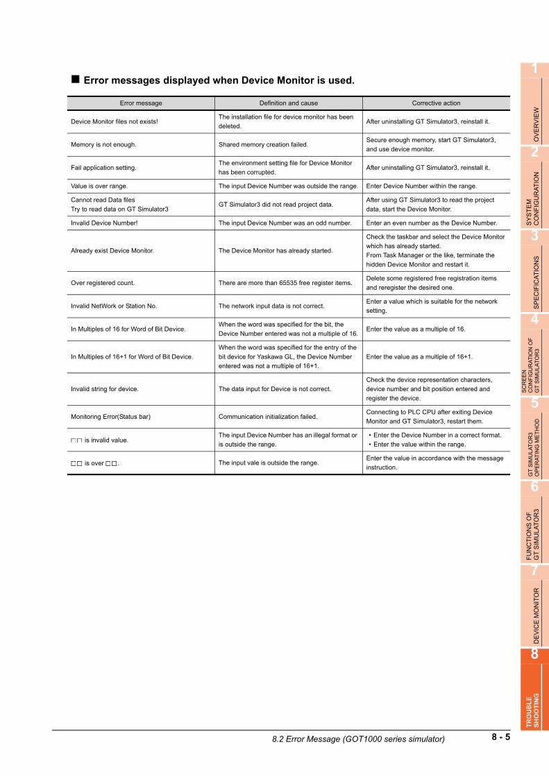
1
OV
ER
VIE
W
2
SY
ST
EM
C
ON
FIG
UR
AT
ION
3
SP
EC
IFIC
AT
ION
S
4
SC
RE
EN
C
ON
FIG
UR
AT
ION
OF
G
T S
IMU
LAT
OR
3
5
GT
SIM
ULA
TO
R3
OP
ER
AT
ING
ME
TH
OD
6
FU
NC
TIO
NS
OF
G
T S
IMU
LA
TO
R3
7
DE
VIC
E M
ON
ITO
R
8
TR
OU
BL
ES
HO
OT
ING
Error messages displayed when Device Monitor is used.
Error message Definition and cause Corrective action
Device Monitor files not exists!The installation file for device monitor has been
deleted.After uninstalling GT Simulator3, reinstall it.
Memory is not enough. Shared memory creation failed.Secure enough memory, start GT Simulator3,
and use device monitor.
Fail application setting.The environment setting file for Device Monitor
has been corrupted.After uninstalling GT Simulator3, reinstall it.
Value is over range. The input Device Number was outside the range. Enter Device Number within the range.
Cannot read Data files
Try to read data on GT Simulator3GT Simulator3 did not read project data.
After using GT Simulator3 to read the project
data, start the Device Monitor.
Invalid Device Number! The input Device Number was an odd number. Enter an even number as the Device Number.
Already exist Device Monitor. The Device Monitor has already started.
Check the taskbar and select the Device Monitor
which has already started.
From Task Manager or the like, terminate the
hidden Device Monitor and restart it.
Over registered count. There are more than 65535 free register items.Delete some registered free registration items
and reregister the desired one.
Invalid NetWork or Station No. The network input data is not correct.Enter a value which is suitable for the network
setting.
In Multiples of 16 for Word of Bit Device.When the word was specified for the bit, the
Device Number entered was not a multiple of 16.Enter the value as a multiple of 16.
In Multiples of 16+1 for Word of Bit Device.
When the word was specified for the entry of the
bit device for Yaskawa GL, the Device Number
entered was not a multiple of 16+1.
Enter the value as a multiple of 16+1.
Invalid string for device. The data input for Device is not correct.
Check the device representation characters,
device number and bit position entered and
register the device.
Monitoring Error(Status bar) Communication initialization failed.Connecting to PLC CPU after exiting Device
Monitor and GT Simulator3, restart them.
is invalid value.The input Device Number has an illegal format or
is outside the range.
• Enter the Device Number in a correct format.
• Enter the value within the range.
is over . The input vale is outside the range.Enter the value in accordance with the message
instruction.
8.2 Error Message (GOT1000 series simulator) 8 - 5

8.3 Error Message (GOT-A900 series simulator)
The following table indicates the error messages occurred in GOT-A900 series simulator themselves, the Descriptions and resolutions.
Error messages displayed when GT Simulator3 is used.
(Continued to next page)
Error message Definition and cause Corrective action
Adobe Reader is not installed correctly.
Please install Adobe Reader.
• Adobe Reader is not installed.
• AdobeReader is not installed correctly.After uninstalling Adobe Reader, reinstall it.
Easysocket is not installed. Perhaps GT Simulator3 is not installed correctly. After uninstalling GT Simulator3, reinstall it.
Cannot terminate 'GT Simulator3'.
Close every dialog and the print preview that are
currently displayed.
• Dialog boxes and the print preview are
displayed.Close all dialog boxes and the print preview.
'GT Simulator3' is not correctly installed.Can not find the Windowsregistry for GT
Simulator3.After uninstalling GT Simulator3, reinstall it.
PLC type of 'GT Simulator3' setting and 'GX
Developer' setting is different.
Please confirm the content of 'GX Developer'
setting or change the PLC type of option setting.
These two CPU type settings are different.Change the CPU type in the GX Developer
project.
Installation path of 'GT Simulator3' cannot be
acquired.Perhaps GT Simulator3 is not installed correctly. After uninstalling GT Simulator3, reinstall it.
This operating environment is unapplicable for
'GT Simulator3'.
Access could not be made to the file necessary
to operate GT Simulator3.
• Check whether the user logs in to Windows
XP, Windows Vista, or Windows 7 as the
user with the administrator authority (for the
computer management).
• Check whether the fast user switching function
or the remote desktop function of Windows
XP, Windows Vista, or Windows 7 is in use.
• GT Simulator3 was not closed propety.
• Illegal process is running.Resart GT Simulator3 after reboot the computer.
Please do logoff/the termination of Windows after
ending 'GT Simulator3'.
Close 'GT Simulator3' before log out or shut
down the Windows.
Close 'GT Simulator3' before log out or shut
down the Windows.
Project Information of 'GX Developer' was not be
acquired.
GPPW.GPS or GPPW.GPJ is not found.
Set a wrong GX Developer project.In Option setting, set the project of GX Developer
again.
8 - 6 8.3 Error Message (GOT-A900 series simulator)

1
OV
ER
VIE
W
2
SY
ST
EM
C
ON
FIG
UR
AT
ION
3
SP
EC
IFIC
AT
ION
S
4
SC
RE
EN
C
ON
FIG
UR
AT
ION
OF
G
T S
IMU
LAT
OR
3
5
GT
SIM
ULA
TO
R3
OP
ER
AT
ING
ME
TH
OD
6
FU
NC
TIO
NS
OF
G
T S
IMU
LA
TO
R3
7
DE
VIC
E M
ON
ITO
R
8
TR
OU
BL
ES
HO
OT
ING
(Continued to next page)
Error message Definition and cause Corrective action
Project path of 'GX Developer' cannot be
acquired.
<cause>
• 'GT Simulator3' is not correctly installed.
• Unsupport PLC type is selected.
• Registry is destroyed.
• Registry information on the project path of GX
Developer was corrupted.
• Unsupport CPU type was specified.
In Option dialog box, set the project of GX
Developer again.
GT Simulator3 is not installed correctly. After uninstalling GT Simulator3, reinstall it.
An illegal project of 'GX Developer' is selected.The project specified in [GX Developer Project] of
Option dialog box does not exist.
Check whether the specified GX Developer
project exists.
'GX Simulator' is not installed.• GX Simulator is not installed.
• GX Simulator is not installed properly.Install GX Simulator.
An illegal project of 'GT Developer' is selected.
(SFC program)
Project cannot be forwarded to 'GX Simulator'
Specified an SFC type GX Developer project.In Option setting, set the project of GX Developer
again.
Failed in the start of 'GX Simulator'.
<ES: ****>
************
(2 different messages in all)
GX Simulator may be not installed correctly.
• After uninstalling GX Simulator, reinstall it.
• Reinstall the update versions of GT
Simulator3, GX Simulator and/or GX
Developer.
Insufficient memory to starting 'GX Simulator'.Not enough Dynamic memory to start up GT
Simulator.
Secure memory space.
• Close unnecessary applications.
• Check free hard disk space.
Failed in the initialization of 'GX Simulator'.
<ES: ****>
************
(32 different messages in all)
GX Simulator may be not installed correctly. After uninstalling GX Simulator, reinstall it.
• GT Simulator3, GX Simulator or GX Developer
was not closed properly.
• Illegal process is running.
• Restart GT Simulator3.
• After restarting the personal computer, restart
GT Simulator3.
• Reinstall the update versions of GT
Simulator3, GX Simulator and/or GX
Developer.
Failed in the start of Shared memory server.
<ES: ****>
************
(2 different messages in all)
• GT Simulator3, GX Simulator or GX Developer
was not closed properly.
• Illegal process is running.
• After restarting the personal computer, restart
GT Simulator3.
• Reinstall the update versions of GT
Simulator3, GX Simulator and/or GX
Developer.
This function can't be used now.Selected an unavailable function in GT
Simulator3.Press [OK].
The version of installed Easysocket is illegal. GT Simulator3 may be not installed correctly. After uninstalling GT Simulator3, reinstall it.
The version of installed 'GX Simulator' is illegal.
Installed an old version of GX Simulator. Install GX Simulator of Version 5E or later.
GT Simulator3 could not work, since language
version for GT Simulator3 was different from one
for GX Simulator.
Install GX Simulator which is compatible with the
same language version as GT Simulator3.
8.3 Error Message (GOT-A900 series simulator) 8 - 7

(Continued to next page)
Error message Definition and cause Corrective action
There is no response from 'GX Simulator' for
terminarion request.
'GX Simulator' is canceled.
Please end 'GT Simulator3' at once and do the
PC in Shutdown.
• The GT Simulator3, GX Simulator or GX
Developer was closed illegally last time.
• Illegal process is running.
• Restart GT Simulator3.
• After restarting the personal computer, restart
GT Simulator3.
The simulation cannot be ended.
Please retry after shutting Dialogue on the
simulation screen.
Since the message such as [This function cannot
be used now] was displayed on the screen, GT
Simulator3 could not be exit correctly.
After selecting [OK] in the dialog box to erase the
on-screen message, exit from GT Simulator3
again.
There was the other internal cause than the
above that did not allow to exit from the software.
After selecting [OK] in the dialog box, wait for
some time and exit from GT Simulator3 again.
Fail in the Snap Shot.
• The GT Simulator3 was closed illegally last
time.
• Illegal process is running.
• Restart GT Simulator3.
• After restarting the personal computer, restart
GT Simulator3.
Communication error occurred.
Retry : Communication begins again.
Cancel : Communication is interrupted.
Please reexecute 'GT Simulator3', if
simulate again.
<ES: ****>
• Cable was disconnected.
• The cable was broken.
After checking for the left causes, choose the
button in the displayed dialog box.
[Retry]
Restarts communication.
[Cancel]
After Cancel is selected, all communications will
not be made.
When performing simulation, restart GT
Simulator3.
Transmission speed (Baud rate) is incorrect.
The PLC CPU type is different from that of the
project setting.
Check communication.
• Cable was disconnected.
• The cable was broken.Check the cable.
Transmission speed (Baud rate) is incorrect.Check the transmission speed (Baud rate) of the
CPU.
The PLC CPU type is different from that of the
project setting.Check the connection target PLC.
Failed in the start of Device Monitor. GT Simulator3 may be not installed correctly. After uninstalling GT Simulator3, reinstall it.
Failed in the end of Device Monitor. GT Simulator3 may be not installed correctly. After uninstalling GT Simulator3, reinstall it.
The path name size is too long.Save the GX Developer under too many directory
levels.
In Option setting, set the project of GX Developer
again.
Parameter file is not found.GT Simulator3 may be not installed correctly. After uninstalling GT Simulator3, reinstall it.
Set a wrong GX Developer project. Create a new project of GX Developer.
An illegal PLC type is selected.In the project of GX Developer, incompatible
CPU type was specified.
Change the CPU type of the project for GX
Developer.
An illegal project of 'GX Developer' is selected.
Project cannot be forwarded to 'GX Simulator'.
Illegal program exists in the GX Developer
project folder.Create a new project of GX Developer.
Program file is not found.
GT Simulator3 may have not been installed
correctly.After uninstalling GT Simulator3, reinstall it.
Illegal project of GX Developer may have been
set.Create a new project of GX Developer.
8 - 8 8.3 Error Message (GOT-A900 series simulator)

1
OV
ER
VIE
W
2
SY
ST
EM
C
ON
FIG
UR
AT
ION
3
SP
EC
IFIC
AT
ION
S
4
SC
RE
EN
C
ON
FIG
UR
AT
ION
OF
G
T S
IMU
LAT
OR
3
5
GT
SIM
ULA
TO
R3
OP
ER
AT
ING
ME
TH
OD
6
FU
NC
TIO
NS
OF
G
T S
IMU
LA
TO
R3
7
DE
VIC
E M
ON
ITO
R
8
TR
OU
BL
ES
HO
OT
ING
Error messages displayed when Device Monitor is used.The same error messages are displayed as those of when GOT1000 series simulator is used.
8.2 Error Message (GOT1000 series simulator)
Error message Definition and cause Corrective action
GOT type of the project is not correct.The GOT type set in the project is other than the
GOT-A900 series (GOT-F900 series).
Change the GOT type of the project created in
GT Designer or GT Designer2 to the GOT-A900
series.
PLC type of the project is different from setting
'GT Simulator3'.
The PLC type set in the project is different from
that in GT Simulator3.
Make correction so that the PLC type of the
project created on GT Designer or GT Designer2
is the same as the CPU type of GT Simulator3.
Project file is not found. Project file is not available. Specify the path of which project data exist.
Cannot access the project file.Access to the specified project data could not be
made.
Check the access privilige of the project data
(e.g. a9gotp.got).
Manual file cannot be found.
Please install manuals.
• GT Manual3 is not installed.
• GT Manual3 is not installed correctly.After uninstalling GT Manual3, reinstall it.
Unsupport PLC is selected.CPU type setting of GT Simulator3 was the
unsupported CPU type.Change the CPU type and restart monitoring.
Failed in reading.
Please retry after checking the following.
• Please close Dialogue if it is displayed.
• Waiting for 'Offline mode'. Please wait at
several seconds.
• Capacity of free disk.
• File access privilege of the project file.
• Project file is illegal or destroyed.
Not enough free disk space.Increase the free space of the hard disk to
100MB or more.
Since the message such as [This function can't
be used now.] is displayed on the screen, read
cannot be performed.
After choosing "OK" in the dialog box to erase the
on-screen message, perform read again.
Waiting for the end processing of the script
function.
(Waiting for offline mode)
After the message "Off-Line processing
execution" appears on the screen, perform read
again.
GT Simulator3 cannot access the project data.Check the access privilege of the project data
(e.g. a9gotp.got).
• This data is not for GOT project.
• The project data was corrupted.Use a correct project data or normal project data.
Failed in reading.
Please retry after checking the following.
• Data size and number of the data.
• Capacity of free disk..
• Please close Dialogue if it is displayed.
• Waiting for 'Offline mode'. Please wait at
several seconds.
• File access privilege of the project file.
• Project file is illegal or destroyed.
Screen data size is too large.Check the screen data size.
( 3.1 GOT that Can Be Simulated)
Not enough user memory. After deleting all, download all user data.
Not enough free disk space.Increase the free space of the hard disk to
200MB or more.
Since the message such as [This function can't
be used now.] is displayed on the screen, read
cannot be performed.
After choosing [OK] in the dialog box to erase the
on-screen message, perform read again.
Waiting for the end processing of the script
function.
(Waiting for offline mode)
After the message [Off-Line processing
execution] appears on the screen, perform read
again.
GT Simulator3 cannot access the project data.Check the access privilege of the project data
(e.g. a9gotp.got).
• This data is not for GOT project.
• The project data was corrupted.Use a correct project data or normal project data.
Fall to delete recipe files.
• Please close recipe file if it is opened.
• Check the file access privilege.
Failed in erasing user data after loading screen
data.
• If there is a user's data opened by another
software, close that file.
• Check the file access privilege.
8.3 Error Message (GOT-A900 series simulator) 8 - 9

8 - 10 8.3 Error Message (GOT-A900 series simulator)

AP
PE
ND
ICE
SIN
DE
X
APPENDICES
Appendix1 Applicable Project Data
Use the same version of GT Simulator3 as that of GT Designer3 that the project data is created.
HINTHINTHINT
When using project data created on GT Designer3 that the version is earlier than that of GT Simulator3
Open the project data on GT Designer3 that the version is the same as that of GT Simulator3, and save the project data.
Refer to the following for point of cautions on using the project data converted with GT Designer before SW3D5C-GOTR-Pack or with GT Converter.
3.3.1 Precautions for using the GT Simulator3
GT Simulator3 version GT Designer3 version
App - 1

App - 2

AP
PE
ND
ICE
SIN
DE
X
INDEX
[A]
Action setupGOT 1000 series simulator .......................... 5-6,5-8GOT-A900 series simulator ............................. 5-13
Applicable CPU ..................................................... 2-5Applicable project data ...................................... App-1
[B]
Basic operation...................................................... 4-1
[C]
Cable ..................................................................... 2-9Communication setup
GOT1000 series simulator ................................. 5-4GOT-A900 series simulator ............................. 5-11
Connection type..................................................... 2-7Converter............................................................. 2-12
[D]
Device Monitor................................................. 4-4,4-5Device monitor....................................................... 7-1
Cascade........................................................... 7-15Changing Device Monitor screen..................... 7-16Delete device ................................................... 7-14Exit ................................................................... 7-11Free Registration screen.................................. 7-14Functions ......................................................... 7-12Menu bar............................................................ 7-4Horizontal......................................................... 7-15Operation environment ...................................... 2-3Operation method .............................................. 7-9Precautions ........................................................ 7-2Register device ................................................ 7-14Restart ............................................................. 7-11Screen configuration .......................................... 7-3Setting.............................................................. 7-17Sort .................................................................. 7-12Starts................................................................ 7-10Status bar........................................................... 7-8Stop.................................................................. 7-11Testing device value ........................................ 7-13Tool Bar ............................................................. 7-5Type ................................................................... 7-6
Device ranges that can be simulatedConnecting to GX Simulator ............................ 3-24Connecting to PLC CPU .................................. 3-23
[E]
End of simulator............................................... 4-4,4-5Environment setup
GOT 1000 series simulator .............................. 5-10GOT-A900 series simulator ............................. 5-14
Error messageGOT1000 series simulator ................................. 8-1GOT-A900 series simulator ............................... 8-6
Executing a simulation......................................... 5-15Exit....................................................................... 5-26
[F]
Functions ............................................................... 6-1
[G]
GOT that can be simulated.................................... 3-1GX Simulator ......................................................... 2-4
[H]
Hard disk space ..................................................... 2-3How to use HELP .................................................. 4-6
[M]
Main menu ............................................................. 5-3Menu bar................................................................ 4-3
[O]
Object script error .................................................. 6-8Open a File .................................................... 4-4,5-18Open a Project.................................4-4,4-5,5-16,5-20Operating procedure
When connecting to GX Simulator2 ................... 5-1When connecting to PLC CPU........................... 5-2
Operation ............................................................. 5-26Option .................................................................... 5-4Option setup .................................................... 4-4,4-5
[P]
Personal computer................................................. 2-3Precautions
Precautions for connecting PLC CPU .............. 3-22Precautions for connecting to GX Simulator .... 3-21Precautions for using the GT Simulator2 ......... 3-13
Print ....................................................................... 6-2Property ................................................................. 6-5
[R]
Read Monitor data ............................................... 5-22
[S]
Screen configuration.............................................. 4-1Script error ............................................................. 6-7Snap shot............................................................... 6-1Specifications......................................................... 3-1Start ............................................................... 5-3,5-15Start of simulator.................................................... 4-4System alarm......................................................... 6-6System configuration
When installing GT Simulator2........................... 2-1When executing GT Simulator2 ......................... 2-2
Index-1

[T]
Tool bar ................................................................. 4-4Troubleshooting..................................................... 8-1Troubleshooting for file save problems.................. 8-1
Index-2

REVISIONS - 1
REVISIONS
* The manual number is given on the bottom left of the back cover.
© 2009 MITSUBISHI ELECTRIC CORPORATION
Print Date * Manual Number Revision
Oct., 2009 SH(NA)-080861ENG-A First printing : Compatible with GT Simulator3 Version1.01B
Jan., 2010 SH(NA)-080861ENG-B Compatible with GT Simulator3 Version1.10L
• Reading GT Designer3 format files (.GTW)
• OMRON PLC (compatible with SYSMAC CJ2 and CP1E)
• Connection with LCPUs supported
May, 2010 SH(NA)-080861ENG-C Compatible with GT Simulator3 Version1.14Q
• Windows 7 supported
• Connection with Q50UDEHCPU and Q100UDEHCPU supported.
Jun., 2010 SH(NA)-080861ENG-D Compatible with GT Simulator3 Version1.17T
• Connection with LJ72GF15-T2 supported
Jan., 2011 SH(NA)-080861ENG-E Compatible with GT Simulator3 Version1.23Z
• Simulation of project data for GT10 supported
• USB connection with FXCPU supported
Apr., 2011 SH(NA)-080861ENG-F Compatible with GT Simulator3 Version1.28E
• GT1655-V supported
• GT Designer3 Help supported
Jul., 2011 SH(NA)-080861ENG-G Compatible with GT Simulator3 Version1.31H
• Windows 7 64-bit OS supported
• Connection with L02CPU-P and L26CPU-PBT supported
Oct., 2011 SH(NA)-080861ENG-H Compatible with GT Simulator3 Version1.37P
• Simulation of project data for GT14 supported
• Description of simulating project data for GT12 added
Jan., 2012 SH(NA)-080861ENG-I Partial corrections
Apr., 2012 SH(NA)-080861ENG-J Compatible with GT Simulator3 Version1.45X
• Connection with FX3GC supported
Sep., 2012 SH(NA)-080861ENG-K Compatible with GT Simulator3 Version1.58L
• The company name of Panasonic Electric Works Co., Ltd. is changed to Panasonic
Corporation.
• The GT14 supports the operator authentication.
• The information site on the Internet is changed to the Mitsubishi Electric Factory
Automation Global Website.
Nov., 2012 SH(NA)-080861ENG-L SAFETY PRECAUTIONS changed
This manual confers no industrial property rights or any rights of any other kind, nor does it confer any patent licenses. Mitsubishi Electric
Corporation cannot be held responsible for any problems involving industrial property rights which may occur as a result of using the
contents noted in this manual.

SH(NA)-080861ENG-L
GOT is a registered trademark of Mitsubishi Electric Corporation.
Microsoft, Windows, Windows NT, Windows Server, Windows Vista, and Windows 7 are registered trademarks or trademarks
of Microsoft Corporation in the United States and other countries.
Adobe and Adobe Reader are registered trademarks of Adobe Systems Incorporated.
Pentium and Celeron are a registered trademarks of Intel Corporation in the United States and other countries.
Ethernet is a registered trademark of Xerox Corporation in the United States.
MODBUS is a trademark of Schneider Electric SA.
VNC is a registered trademark of RealVNC Ltd. in the United States and other countries.
Other company and product names herein are either trademarks or registered trademarks of their respective owners.

GT Simulator3 Version1
Integrated FA Software
MODEL
MODELCODE
SW1-GTSIM3-O-E
1D7MB1
SH(NA)-080861ENG-L(1211)MEE
for GT Works3Operating Manual for GT Works3
Specifications subject to change without notice.
Printed in Japan, November 2012.
When exported from Japan, this manual does not require application to the
Ministry of Economy, Trade and Industry for service transaction permission.
HEAD OFFICE : TOKYO BUILDING, 2-7-3 MARUNOUCHI, CHIYODA-KU, TOKYO 100-8310, JAPAN
NAGOYA WORKS : 1-14 , YADA-MINAMI 5-CHOME , HIGASHI-KU, NAGOYA , JAPAN

HEADQUARTERS
EUROPEMITSUBISHI ELECTRIC EUROPE B.V.German BranchGothaer Straße 8D-40880 RatingenPhone: +49 (0)2102 / 486-0Fax: +49 (0)2102 / 486-1120
CZECH REP.MITSUBISHI ELECTRIC EUROPE B.V.-org.sl.Czech BranchAvenir Business Park, Radlická 714/113aCZ-158 00 Praha 5Phone: +420 - 251 551 470Fax: +420 - 251-551-471
FRANCEMITSUBISHI ELECTRIC EUROPE B.V.French Branch25, Boulevard des BouvetsF-92741 Nanterre CedexPhone: +33 (0)1 / 55 68 55 68Fax: +33 (0)1 / 55 68 57 57
IRELANDMITSUBISHI ELECTRIC EUROPE B.V.Irish BranchWestgate Business Park, BallymountIRL-Dublin 24Phone: +353 (0)1 4198800Fax: +353 (0)1 4198890
ITALYMITSUBISHI ELECTRIC EUROPE B.V.Italian BranchViale Colleoni 7I-20041 Agrate Brianza (MB)Phone: +39 039 / 60 53 1Fax: +39 039 / 60 53 312
POLANDMITSUBISHI ELECTRIC EUROPE B.V.Poland BranchKrakowska 50PL-32-083 BalicePhone: +48 (0)12 / 630 47 00Fax: +48 (0)12 / 630 47 01
RUSSIAMITSUBISHI ELECTRIC EUROPE B.V.52, bld. 3 Kosmodamianskaya nab 8 floorRU-115054 МoscowPhone: +7 495 721-2070Fax: +7 495 721-2071
SPAINMITSUBISHI ELECTRIC EUROPE B.V.Spanish BranchCarretera de Rubí 76-80E-08190 Sant Cugat del Vallés (Barcelona)Phone: 902 131121 // +34 935653131Fax: +34 935891579
UKMITSUBISHI ELECTRIC EUROPE B.V.UK BranchTravellers LaneUK-Hatfield, Herts. AL10 8XBPhone: +44 (0)1707 / 27 61 00Fax: +44 (0)1707 / 27 86 95
JAPANMITSUBISHI ELECTRIC CORPORATIONOffice Tower “Z” 14 F8-12,1 chome, Harumi Chuo-KuTokyo 104-6212Phone: +81 3 622 160 60Fax: +81 3 622 160 75
USAMITSUBISHI ELECTRIC AUTOMATION, Inc.500 Corporate Woods ParkwayVernon Hills, IL 60061Phone: +1 847 478 21 00Fax: +1 847 478 22 53
EUROPEAN REPRESENTATIVES
AUSTRIAGEVAWiener Straße 89AT-2500 BadenPhone: +43 (0)2252 / 85 55 20Fax: +43 (0)2252 / 488 60
BELARUSTECHNIKONOktyabrskaya 19, Off. 705BY-220030 MinskPhone: +375 (0)17 / 210 46 26Fax: +375 (0)17 / 210 46 26
BELGIUMESCO DRIVES & AUTOMATIONCulliganlaan 3BE-1831 DiegemPhone: +32 (0)2 / 717 64 30Fax: +32 (0)2 / 717 64 31
BELGIUMKoning & Hartman b.v.Woluwelaan 31BE-1800 VilvoordePhone: +32 (0)2 / 257 02 40Fax: +32 (0)2 / 257 02 49
BOSNIA AND HERZEGOVINAINEA RBT d.o.o.Aleja Lipa 56BA-71000 SarajevoPhone: +387 (0)33 / 921 164Fax: +387 (0)33/ 524 539
BULGARIAAKHNATON4, Andrei Ljapchev Blvd., PO Box 21BG-1756 SofiaPhone: +359 (0)2 / 817 6000Fax: +359 (0)2 / 97 44 06 1
CROATIAINEA RBT d.o.o.Losinjska 4 aHR-10000 ZagrebPhone: +385 (0)1 / 36 940 - 01/ -02/ -03Fax: +385 (0)1 / 36 940 - 03
CZECH REPUBLICAutoCont C.S. s.r.o.Technologická 374/6CZ-708 00 Ostrava-PustkovecPhone: +420 595 691 150Fax: +420 595 691 199
DENMARKBeijer Electronics A/SLykkegårdsvej 17DK-4000 RoskildePhone: +45 (0)46/ 75 76 66Fax: +45 (0)46 / 75 56 26
ESTONIABeijer Electronics Eesti OÜPärnu mnt.160iEE-11317 TallinnPhone: +372 (0)6 / 51 81 40Fax: +372 (0)6 / 51 81 49
FINLANDBeijer Electronics OYPeltoie 37FIN-28400 UlvilaPhone: +358 (0)207 / 463 540Fax: +358 (0)207 / 463 541
GREECEUTECO5, Mavrogenous Str.GR-18542 PiraeusPhone: +30 211 / 1206 900Fax: +30 211 / 1206 999
HUNGARYMELTRADE Kft.Fertő utca 14.HU-1107 BudapestPhone: +36 (0)1 / 431-9726Fax: +36 (0)1 / 431-9727
LATVIABeijer Electronics SIARitausmas iela 23LV-1058 RigaPhone: +371 (0)784 / 2280Fax: +371 (0)784 / 2281
LITHUANIABeijer Electronics UABSavanoriu Pr. 187LT-02300 VilniusPhone: +370 (0)5 / 232 3101Fax: +370 (0)5 / 232 2980
EUROPEAN REPRESENTATIVES
MALTAALFATRADE Ltd.99, Paola HillMalta- Paola PLA 1702Phone: +356 (0)21 / 697 816Fax: +356 (0)21 / 697 817
MOLDOVAINTEHSIS srlbld. Traian 23/1MD-2060 KishinevPhone: +373 (0)22 / 66 4242Fax: +373 (0)22 / 66 4280
NETHERLANDSHIFLEX AUTOM.TECHNIEK B.V.Wolweverstraat 22NL-2984 CD RidderkerkPhone: +31 (0)180 – 46 60 04Fax: +31 (0)180 – 44 23 55
NETHERLANDSKoning & Hartman b.v.Haarlerbergweg 21-23NL-1101 CH AmsterdamPhone: +31 (0)20 / 587 76 00Fax: +31 (0)20 / 587 76 05
NORWAYBeijer Electronics ASPostboks 487NO-3002 DrammenPhone: +47 (0)32 / 24 30 00Fax: +47 (0)32 / 84 85 77
PORTUGALFonseca S.A.R. João Francisco do Casal 87/89PT - 3801-997 Aveiro, EsgueiraPhone: +351 (0)234 / 303 900Fax: +351 (0)234 / 303 910
ROMANIASirius Trading & Services srlAleea Lacul Morii Nr. 3RO-060841 Bucuresti, Sector 6Phone: +40 (0)21 / 430 40 06Fax: +40 (0)21 / 430 40 02
SERBIAINEA RBT d.o.o.Izletnicka 10SER-113000 SmederevoPhone: +381 (0)26 / 615 401Fax: +381 (0)26 / 615 401
SLOVAKIASIMAP s.r.o.Jána Derku 1671SK-911 01 TrencínPhone: +421 (0)32 743 04 72Fax: +421 (0)32 743 75 20
SLOVAKIAPROCONT, spol. s r.o. PrešovKúpelná 1/ASK-080 01 PrešovPhone: +421 (0)51 7580 611Fax: +421 (0)51 7580 650
SLOVENIAINEA RBT d.o.o.Stegne 11SI-1000 LjubljanaPhone: +386 (0)1 / 513 8116Fax: +386 (0)1 / 513 8170
SWEDENBeijer Electronics ABBox 426SE-20124 MalmöPhone: +46 (0)40 / 35 86 00Fax: +46 (0)40 / 93 23 01
SWITZERLANDOmni Ray AGIm Schörli 5CH-8600 DübendorfPhone: +41 (0)44 / 802 28 80Fax: +41 (0)44 / 802 28 28
TURKEYGTSBayraktar Bulvari Nutuk Sok. No:5TR-34775 Yukarı Dudullu-Ümraniye-İSTANBULPhone: +90 (0)216 526 39 90Fax: +90 (0)216 526 3995
UKRAINECSC Automation Ltd.4-B, M. Raskovoyi St.UA-02660 KievPhone: +380 (0)44 / 494 33 55Fax: +380 (0)44 / 494-33-66
EURASIAN REPRESENTATIVES
KAZAKHSTANTOO KazpromavtomatikaUl. Zhambyla 28KAZ-100017 KaragandaPhone: +7 7212 / 50 10 00Fax: +7 7212 / 50 11 50
MIDDLE EAST REPRESENTATIVES
EGYPTI.C. SYSTEMS LTD.23 Al-Saad-Al-Alee St.EG-Sarayat, Maadi, CairoPhone: +20 (0) 2 / 235 98 548Fax: +20 (0) 2 / 235 96 625
ISRAELILAN & GAVISH Ltd.24 Shenkar St., Kiryat ArieIL-49001 Petah-TiqvaPhone: +972 (0)3 / 922 18 24Fax: +972 (0)3 / 924 0761
ISRAELGIRIT CELADON LTD12 H'aomanut StreetIL-42505 NetanyaPhone: +972 (0)9 / 863 39 80Fax: +972 (0)9 / 885 24 30
LEBANONCEG INTERNATIONALCebaco Center/Block A Autostrade DORALebanon - BeirutPhone: +961 (0)1 / 240 430Fax: +961 (0)1 / 240 438
AFRICAN REPRESENTATIVE
SOUTH AFRICACBI Ltd.Private Bag 2016ZA-1600 IsandoPhone: + 27 (0)11 / 977 0770Fax: + 27 (0)11 / 977 0761
Mitsubishi Electric Europe B.V. /// FA - European Business Group /// Gothaer Straße 8 /// D-40880 Ratingen /// GermanyTel.: +49(0)2102-4860 /// Fax: +49(0)2102-4861120 /// [email protected] /// www.mitsubishi-automation.com
MITSUBISHI ELECTRIC


![Ý > ) > § > Á > ä > > » > ) > Â > > ¬ > æ > ¥ > C > Â > ´ > · PDF fileI µ\µ\ó ò « ó Â Ø i\Ø X N : Ë\¿\ý\ ° ¬ ¯\Ø Í\¶ ù ö]c ® â\Á\Ð\®\õ ® Ã\Ø](https://img.dokumen.tips/doc/110x75/5aafe7837f8b9a59478de92f/-c-i-x-n-c-0-u-drmdh-.jpg)


![entgrenzt Ausgabe 10 · PDF file2hk=>k nl@>lm:emng@=>k>b @>gmebg':km>lheem>gpbkngl=:a>k#>=:g d>g];>k=>g n?;:n=>k/>bm> :elh];>k=b> 679,6](https://img.dokumen.tips/doc/110x75/5a785d047f8b9a77438bcf14/entgrenzt-ausgabe-10-a-2hkk-nllmemngkb-gmebgkmlheemgpbknglakg.jpg)
![FA Equipment for Beginners(HMIs) THA.ppt [互換モード]...HMI tq:fu GT Simulator3 Mitsubishi Electric PC HMI RS-232C PC USB HMI PLC 000 HMI PLC FA Equipment for Beginners(HMIs)](https://img.dokumen.tips/doc/110x75/5e459b24cf716854423e8a33/fa-equipment-for-beginnershmis-thappt-fff-hmi-tqfu-gt-simulator3.jpg)


![>> den=[1 10 20+Kp]; >> step(num,den,t); >> den=[1 10 20 ... · PDF file>> Kp=100; >> num=[Kp]; >> den=[1 10 20+Kp]; >> t=0:0.01:2; >> step(num,den,t); >> hold on; >> Kp=300; >> num=[Kp];](https://img.dokumen.tips/doc/110x75/5a814ad57f8b9aa24f8d2159/den1-10-20kp-stepnumdent-den1-10-20-kp100-numkp-den1-10.jpg)