Embed Size (px)
Citation preview

Integrated computer-aided optimal design and finite element analysis of a plain milling cutter
Nand K. Jha and Kathryn Hornik
Mechanical Engineering Department, Manhattan College, Riverdale, NY, USA
Thispaperpresents the computer-aided integration of solidmodelling, optimization, andjinite element analysis. Interactive (three-dimensional) solid modelling is used in the development of relatively eficient and fast solutions to the many constraints and/or limitations encountered in the design process. The study also addresses the fatigue analysis using 3DJinite element analysis on a workstation. Throughout the study, interactive 30 solid modelling is used in the development of a practical and economical design procedure. The research highlights the interactive and integrated nature of the design tasks. An optimal formulation of an automatic design algorithm is also carried out. The cost minimization objective function along with design constraints and behavior constraints are developed. The optimal design parameters thus obtained are tested for stresses at the tip of the tool and at the jillets. Interactive application of optimization, solid modelling, and finite element techniques produce the acceptable optimal design. The design methodoIogy presented in this paper is general and generic in nature. This has been illustrated through an example of design of a plain milling cutter.
Keywords: I-DEAS, optimal design, finite element analysis, integrated design and analysis
1. Introduction
Traditionally cutting tools are designed by empirical relationships. l*’ Manufacturing engineers have long recognized the inefficiency of the approach. The major weaknesses of this traditional approach is the unsyste- matic manner of its application. The systematic manner of cutting tool design should be the computation of all design parameters simultaneously so that interrelation- ships and interactions of all design parameters can be taken into account3 The approach is illustrated in Figure I.
Many kinds and sizes of cutters are needed for the large variety of work that can be done by milling. Many standard cutters are available, but when they are not adequate, special cutters are designed. A cutter is often named for the kind of milling operations it performs. Milling cutters are made of various diameters, lengths, widths, and numbers of teeth and may be of the solid, tipped, or inserted tooth types with the same materials as for single-point tools.2
The cutter design being presented in this paper is useful for single point as well as for multi-point cutters such as those used for turning and milling. In fact, the design principles for both single and multi-point cutters are similar. The design parameters such as rake angle,
Address reprint requests to Prof. Nand K. Jha at the Mechanical Engineering Department, Manhattan College, Riverdale, NY 10471, USA.
Received 16 February 1993; revised 12 December 1994; accepted 16 January 1995
Appl. Math. Modelling 1995, Vol. 19, June 0 1995 by Elsevier Science Inc. 655 Avenue of the Americas, New York, NY 10010
clearance angle of tooth, and height of tooth are common in both single point and multi-point cutters. Addition- ally, cutting parameters such as speed of rotation, feed, and depth of cut are also similar. However, parameters such as diameter of the cutter, number of teeth on the cutter, and angular spacing of teeth are exclusively associated with milling cutters.2
In the family of milling operations such as plain milling, slot milling, side milling, end milling, face milling, and form milling, design parameters differ only in their
ACCEPTABLE PRINT OUT
Figure 1. Integrated computer-aided design scheme
0307-904x/95/$10.00 SSDI 0307404X(95)0001 l-8
CORE Metadata, citation and similar papers at core.ac.uk
Provided by Elsevier - Publisher Connector
Analysis of a plain milling cutter: N. K. Jha and K. Hornik
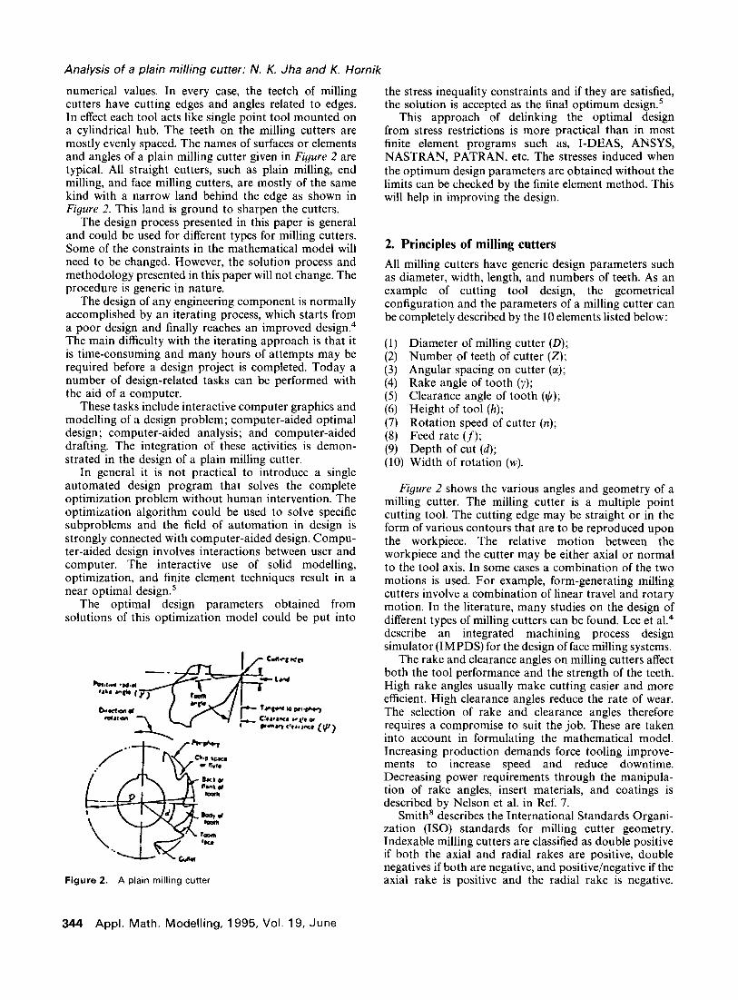
numerical values. In every case, the teetch of milling cutters have cutting edges and angles related to edges. In effect each tool acts like single point tool mounted on a cylindrical hub. The teeth on the milling cutters are mostly evenly spaced. The names of surfaces or elements and angles of a plain milling cutter given in Figure 2 are typical. All straight cutters, such as plain milling, end milling, and face milling cutters, are mostly of the same kind with a narrow land behind the edge as shown in Figure 2. This land is ground to sharpen the cutters.
The design process presented in this paper is general and could be used for different types for milling cutters. Some of the constraints in the mathematical model will need to be changed. However, the solution process and methodology presented in this paper will not change. The procedure is generic in nature.
The design of any engineering component is normally accomplished by an iterating process, which starts from a poor design and finally reaches an improved design4 The main difficulty with the iterating approach is that it is time-consuming and many hours of attempts may be required before a design project is completed. Today a number of design-related tasks can be performed with the aid of a computer.
These tasks include interactive computer graphics and modelling of a design problem; computer-aided optimal design; computer-aided analysis; and computer-aided drafting. The integration of these activities is demon- strated in the design of a plain milling cutter.
In general it is not practical to introduce a single automated design program that solves the complete optimization problem without human intervention. The optimization algorithm could be used to solve specific subproblems and the field of automation in design is strongly connected with computer-aided design. Compu- ter-aided design involves interactions between user and computer. The interactive use of solid modelling, optimization, and finite element techniques result in a near optimal design.’
The optimal design parameters obtained from solutions of this optimization model could be put into
Figure 2. A plain milling cutter
the stress inequality constraints and if they are satisfied, the solution is accepted as the final optimum design.’
This approach of delinking the optimal design from stress restrictions is more practical than in most finite element programs such as, I-DEAS, ANSYS, NASTRAN, PATRAN, etc. The stresses induced when the optimum design parameters are obtained without the limits can be checked by the finite element method. This will help in improving the design.
2. Principles of milling cutters
All milling cutters have generic design parameters such as diameter, width, length, and numbers of teeth. As an example of cutting tool design, the geometrical configuration and the parameters of a milling cutter can be completely described by the 10 elements listed below:
Diameter of milling cutter (D); Number of teeth of cutter (Z); Angular spacing on cutter (~1); Rake angle of tooth (7); Clearance angle of tooth (9); Height of tool (h); Rotation speed of cutter (n); Feed rate (f); Depth of cut (d);
(10) Width of rotation (w).
Figure 2 shows the various angles and geometry of a milling cutter. The milling cutter is a multiple point cutting tool. The cutting edge may be straight or in the form of various contours that are to be reproduced upon the workpiece. The relative motion between the workpiece and the cutter may be either axial or normal to the tool axis. In some cases a combination of the two motions is used. For example, form-generating milling cutters involve a combination of linear travel and rotary motion. In the literature, many studies on the design of different types of milling cutters can be found. Lee et a1.4 describe an integrated machining process design simulator (IMPDS) for the design of face milling systems.
The rake and clearance angles on milling cutters affect both the tool performance and the strength of the teeth. High rake angles usually make cutting easier and more efficient. High clearance angles reduce the rate of wear. The selection of rake and clearance angles therefore requires a compromise to suit the job. These are taken into account in formulating the mathematical model. Increasing production demands force tooling improve- ments to increase speed and reduce downtime. Decreasing power requirements through the manipula- tion of rake angles, insert materials, and coatings is described by Nelson et al. in Ref. 7.
Smith’ describes the International Standards Organi- zation (ISO) standards for milling cutter geometry. Indexable milling cutters are classified as double positive if both the axial and radial rakes are positive, double negatives if both are negative, and positive/negative if the axial rake is positive and the radial rake is negative.
344 Appl. Math. Modelling, 1995, Vol. 19, June
Analysis of a plain milling cutter: N. K. Jha and K. Hornik
However, these geometric descriptions make the mathematical formulation for design fairly complex.
Mohan’ describes profile relieve cutters in milling contour surfaces. Profiles of these relieving tools are similar to the profile of the contour to be milled by the milling cutter, if the milling cutter is designed with a zero degree rake angle and straight flutes/gashes. In milling helical surfaces, the geometrical and dimensional accuracy of the profile cutter and its tool-life behavior is very important.
Davies” describes bonding of carbide inserts to such tools as end-mills instead of brazing them. He outlines development of such a technique and optimization of the tool design for bonding, selection of adhesives, cutting tests (using 0.14% carbon steel workpiece), and an assessment of temperature developed in the tool.
Milling plays a central role as a shape generating technique in the machining of hollow forms. Such hollow shapes are used in tools for presses, forges, and foundry work. Granger’ ’ describes the selection of a milling cutter in terms of average chip thickness rather than in feed/tooth. This approach depends on a combination of factors including material, component design, strength, rigidity of fixturing, and type and age of machine.
Agullo-Batlle et al. I2 describe the development of a CAD method that produces the tool axial profile required to obtain a drill of a given cross-section profile.
The easier cutting capability of high-rake angle face milling cutters is revisited in view of the emergence of lighter CNC machining centers (5-15 hp spindles) and availability of indexable carbide inserts with sharp edges. A reduced power consumption by 20% in high positive axial-rake design produces smooth machining, better surface finish, and less machine wear.
Apart from the geometrical considerations in the design of a milling cutter, the cutter operating conditions must be set-up. There are three important operating conditions which must be determined in advance. These are cutting speed (n), the feed (f), and the depth of the cut (d).
It has long been recognized that it is more efficient to remove metal in the form of thick chips than thin ones, so the maximum possible feed rate should be used. But the maximum feed is limited by the following factors: (1) the cutting edge strength, (2) the rigidity and allowable deflection, (3) the surface finish required, and (4) the tool chip space. The cutting speed will also affect the chip thickness and in turn the rate of metal removal. The depth of cut will also affect the chip thickness. Sometimes it is difficult to include these conflicting factors in the mathematical model.
3. Mathematical model for a plain milling cutter design
A computer-aided model suitable to CAD/CAM systems and based on an analysis of cutting mechanics is developed for the prediction of forces, torques, and power in plain milling operations. The mathematical models presented below are general in nature. Almost all milling cutters will have similar mathematical models,
only differing in numerical values. The computer-aided design enables most cutting tool calculating to be performed with the desired accuracy.
While the cost of the milling cutters represents only approximately 2.5% of the entire investment in manufacturing, their influence on the entire production process is far larger. Consequently, dividends paid by the milling operation largely depend on milling cutter performance and hence, its design.
An objective function is developed to approximate the cost of milling for the optimum design of milling cutters. This is important because the cost of milling will differ with different types of mills. The objective function is influenced greatly by the kinematics of cutting, for example, the number of rotations, the rate of feed, and the depth of cutting. Besides these, the geometric feature of the cutter, including diameter of the milling cutter (D), the number of teeth on the cutter (Z), the spacing of teeth of the cutter, and the geometrical configuration of the tooth are also involved.
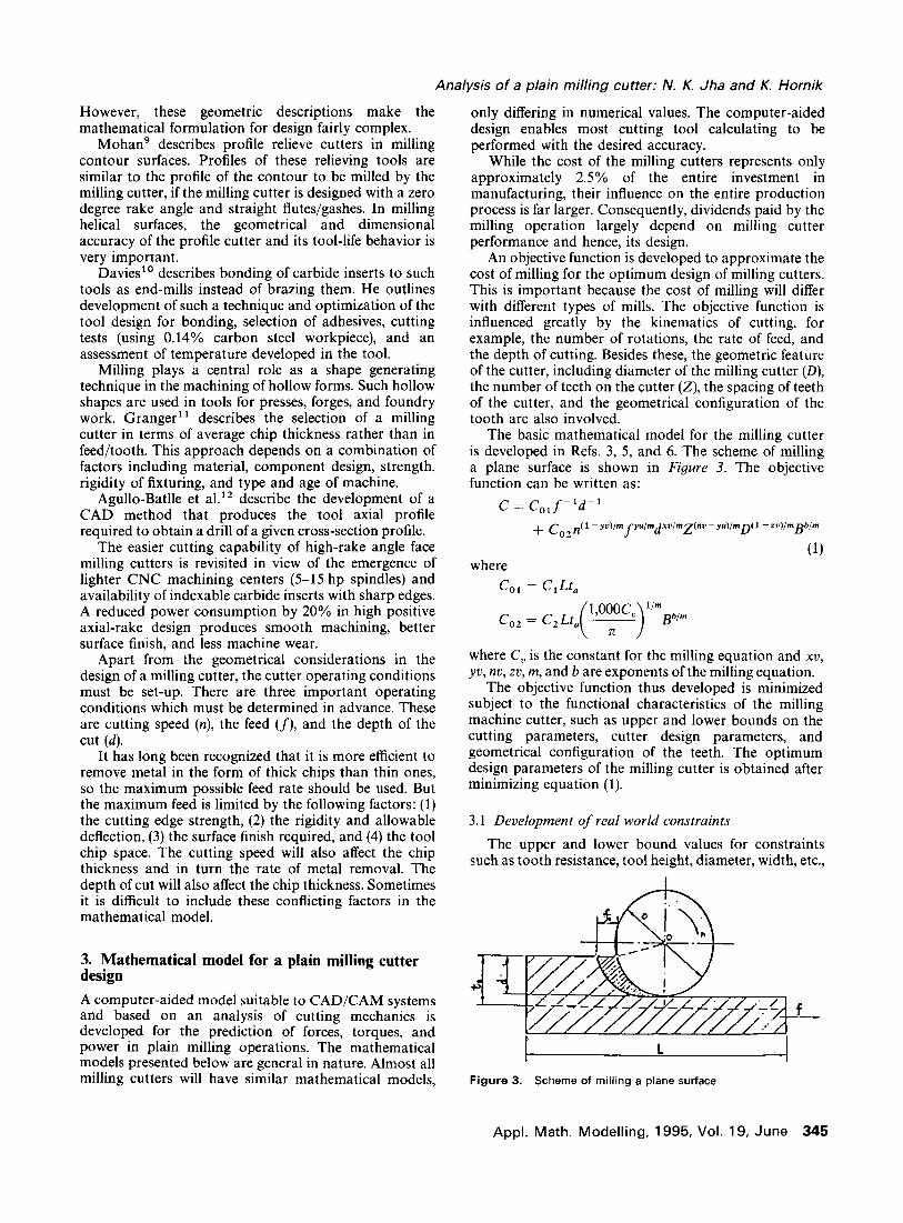
The basic mathematical model for the milling cutter is developed in Refs. 3, 5, and 6. The scheme of milling a plane surface is shown in Figure 3. The objective function can be written as:
C = C,,f- ‘d-’
where
+ co2 n( I- wWmfyulmp/mp~ - wVml)( I- N/mgbh
(1)
co, = C,Lt,
Bb’”
where C, is the constant for the milling equation and xv, yv, nv, zv, m, and b are exponents of the milling equation.
The objective function thus developed is minimized subject to the functional characteristics of the milling machine cutter, such as upper and lower bounds on the cutting parameters, cutter design parameters, and geometrical configuration of the teeth. The optimum design parameters of the milling cutter is obtained after minimizing equation (1).
3.1 Development of real world constraints
The upper and lower bound values for constraints such as tooth resistance, tool height, diameter, width, etc.,
Figure 3. Scheme of milling a plane surface
Appl. Math. Modelling, 1995, Vol. 19, June 345

Analysis of a plain milling cutter: N. K. Jha and K. Hornik
are likely to differ for different types of cutter. The following real world constraints are developed for the plain milling cutter design presented in this article.
(1)
(2)
(3)
(4)
(5)
(6)
(7)
(8)
Maximum feed rate constraint:
C,,f 5 1 (2)
where C,, = l/f,,,, and f,_ is the maximum permissible feed rate.
Minimum feed rate constraint:
&if-’ I 1 (3)
where C - f 21 - min3 and fmin is the minimum feed rate permissible.
Maximum speed constraint:
C,,n 5 1 (4)
C3 1 = l/nmax, and nmax is the maximum speed possible on the milling machine.
Minimum speed constraint:
C,,n-’ - 1 (5)
C,, = nmin, and nmin is the minimum speed possible on the milling machine.
Horse power constraint:
C,,Z” -Yf)fYl@l _YS)dYf < 1 -
where
(6)
c51 =
&ITB
6.12 x 10%/P
where q is the efficiency and P is the power of the machine tool.
Maximum loading on feeding mechanism constraint:
C,, fYfZ(l-Yf),-YrdYfD-Yf 5 1 (7)
where
Csl = 9 F,
and where F, is the allowable load on the feeding mechanism.
Maximum depth of cut constraint:
C,,d I 1 (8)
where C,, = l/d,,,, and d,,, is the maximum depth of cut.
Minimum depth of cut constraint:
C,,d-’ I 1 (9)
where CB1 = dmin, and dmin is the minimum depth of cut.
(9) Milling cutter tooth resistance constraint:
CsldxffYfn -yfz(l -Yf)D-Y/h < 1
where
(10)
(10) At least two teeth in contact constraint:
ClolZd0.5D-0.5 I 1
where Cl,, = l/z.
(11) Surface roughness constraint:
ClllZ-2D-1n-2f -2 < 1 - (12)
where Cl,, = 0.25R,, where R, is the maximum allowable surface roughness.
(12) Maximum diameter of cutter:
C,,,D I 1 (13)
where Cl,, = l/D,,,, and D,,, is the macimum possible diameter of the cutter.
(13) Minimum diameter of cutter constraint:
C13,D-’ I 1 (14)
where C13, = Dmin, and Dmin is the minimum possible diameter of the cutter.
(14) Angular pitch constraint:
c,,,z-‘a-’ < 1 (15)
where Cl,, = 360 and where u is the angular pitch (in degrees).
(15) Tooth height constraint:
C,,,hZD-’ I 1
where C15i = l/1.2.
(16) Bending stress constraint: This constraint is specifically developed for milling cutter design. It is assumed that the tooth of the cutter would act as a cantilever beam under a distributed load. The load, F,, was considered to be acting at the midway point on the tooth. The constraint was developed as follows (refer to Figure 6):
W c,, =- a,W
W = 7 (section modulus)
b= x[D _ h*(DIZ)]
Z (width of tool base)
where h is height of the tooth, and aa is the allowable stress of the cutter material.
(11)
(16)
M=F, h-i ( )
MC M’12 6M ab=-=_
I wt3/12 = Wt2 Y
(164
(16b)
346 Appl. Math. Modelling, 1995, Vol. 19, June

Analysis of a plain milling cutter: N. K. Jha and K. Hornik
Substituting (16a) into (16b) gives
6F,
wr2 ’ IOb
where
r=$
which results in
12F,z(h - 0.5d) < ~
TCDW - b
Finally it is presented as
C,,,ZhD-’ - C,,,dD-’ I 1
where
(17)
C 1-a
161 - 7ttSbW
c 162 =6F,
7cab w
(17) Fatigue constraint: The fatigue constraint is very important for this design problem since each tooth experiences an alternating load. Assuming the maximum alternating load to be F,/4, as two teeth are in contact, the modified Goodman theory is used to develop the fatigue constraint. The factor of safety (f.o.s) was assumed to be 2.
where
F, Fa F, Faz a,=a,=-===-=--
4A 4wr 4wg 27cwD
The modified Goodman relation then becomes
Fz Fz a + a = 0.5 27rwDS, 2nwDS,
C,,,ZD-’ I 1
where
(18)
C
(18) Non-negativity constraint:
D20,n20,d20,Z20,f20,h20,cr20
xv, yv, zv, and m are exponents, obtained from Refs. 1 and 2.
4. Example and optimal solution
A plain milling cutter with straight teeth is to be designed for milling a plain carbon steel workpiece of length
200 mm and width 38 mm. The maximum material to be removed is 6 mm. The milling arbor diameter is 22 mm. The milling machine is equipped with a motor of 3.5 kW and the efficiency of the milling machine mechanism is 85%. The feed of the milling machine is in the range of 11-125 mm/min. The machinist hourly wage is $6, and the tool change/resharpening cost is $6/hr. The cutter material is high-speed steel.
The solution of the mathematical model is obtained through the generalized reduced gradient (GRG) nonlinear optimization technique for the data in the example. The IMSLS subroutine library was used on a VAX-8350. The generalized reduced gradient method is generally of the following form:
Minimize F(X); X=[Xl,X2,X,,...,X,]T~RN
(19) Subject to g,,,(X) g 0, m= 1, 2,3 ,..., M
(20)
M equality constraints.
xi” < xi < Xl”’ (21)
In generalized reduced gradient method, the design vector X is divided into two classes: (1) decision variables and (2) state variables.
x = {KZ}’
The decision variables are independent, and the state variables are slaves to the decision variables used only to satisfy the constraints. The reduced gradient is the rate of change of the objective function with respect to decision variables adjusted to maintain feasibility. Geometrically, the reduced gradient can be described as a projection of the original N-dimensional gradient onto the Q-dimensional feasible region described by the decision variables. Hence, the reduced gradient can be used in the same manner as the full gradient to search for a minimum of F(X) in the reduced space. The state variables are adjusted during the course of the search to maintain feasibility.
The method finds the optimal solution after assuming initial values of the design parameters d, z, D, n, f, h and y, the rake angle. The number of teeth must be an integer but the method gives continuous values and hence it is approximated to integer values such that it does not violate the constraints. The optimal values obtained for the cutter geometry and cutting variables are shown below. The CPU time for this problem is about 1.5 min. Clearly, the generalized reduced gradient method is robust. From our experience, it looked like that method was insensitive to problem condition and, therefore not generally in need of special problem scaling. The detail of the optimization mechanism is avoided due to the lack of space. The design parameters obtained are as follows:
f* (feed) = 125 mm/min, d * (depth of the cut) = 6 mm, n* (rpm) = 100, Z* (# of teeth) = 8, D* (diameter of the cutter) = 64 mm, h* (tooth height) = 6 mm, y* (rake angle) = 15”
Appl. Math. Modelling, 1995, Vol. 19, June 347
Analysis of a plain milling cutter: N. K. Jha and K. Hornik
Table 1. Cutter geometry
Name Symbol Value
Rake angle Diameter Face thickness Number of teeth Height of tooth Angular spacing Clearance angle Land
; 15”
64 mm W 38 mm
8 f, 6mm
45”
4 5”
3.2 mm
The full cutter geometry along with angular spacing (ct), clearance angle ($), and land (1) are presented in Table I.
After getting a near optimal solution, the solid model of a plain milling cutter is created.
5. Solid modelling of milling cutter
A solid model of the plain milling cutter is developed on an IBM-RS/6000 workstation. The solid modelling package used is called IDEAS developed by Structural Dynamics Research Corporation (SDRC). IDEAS is an acronym for Integrated Design Engineering Analysis System, a software that runs on a variety of computing hardware platforms. CAEDS is an acronym for Computer Aided Engineering Design System, a software that runs on IBM computers. IDEAS and CAEDS are functionally identical to each other.
In the design of a plain milling cutter, the user has to develop a solid model from primitives by using Boolean operations. If primitives are not already stored, they could be created by “sweeping” or rotating a 2D profile or structure. After the solid modelling, the optimization and finite element analysis techniques are used to improve the design and to check stresses. The design process is iterating and starts from a poor design and reaches to an improved design and/or optimal design.
Solid modelling techniques are based on information- ally complete, valid, and unambiguous representations of objects. User input required to create solid models on existing CAD/CAM systems depend upon both the internal representation scheme used by each system as well as the user interface. It is crucial to distinguish between the user interface and the internal data representation of a given CAD/CAM system. The two are quite separate aspects of the system and can be linked together by software that is transparent to the user. For example, a system that has a B-rep (boundary representation) internal data representation may use a constructive solid geometry) CSG oriented user interface; that is; input a solid model by its primitives. Most systems use the building-block approach (CSG) and sweep orientation as the basis for their interface. This approach was used in creating the solid model for the plain milling cutter. The approach is quite general and could be quickly modified to create other milling cutters.
A solid model so created of the plain milling cutter is a more complete representation than its surface model.
348 Appl. Math. Modelling, 1995, Vol. 19, June
It is unique from the latter in the topological information it stores, which potentially permits functional automa- tion and integration. For example, the mass property calculation or finite element mesh of the cutter was generated automatically, without any manual interven- tion. Typically, a solid model consists of both topological and geometrical data of its corresponding object.
The solid model of the plain milling cutter is developed as follows:
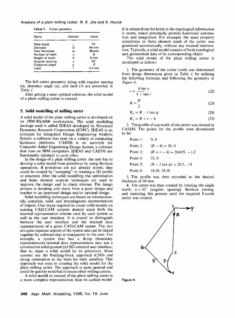
1. The geometry of the cutter tooth was determined from design dimensions given in Table I, by utilizing the following formulas and following the geometry in Figure 4.
htancc r=
1 + tarry (22)
(23)
R, = R - 1 tan II/ (24)
R,=R+r-h (25)
2. The profile of one tooth of the cutter was created in CAEDS. The points for the profile were determined to be:
Point 1: 0, 0
Point 2: (R - h) = 26,O
Point 3: (R + r - h) = 26.635, - 1.2
Point 4: 32, 0
Point 5: (R - 1 tan Ic/) = 29.5, -9
Point 6: 18.38, 18.38
3. The profile was then extruded to the desired thickness of 38 mm.
4. The cutter was then created by rotating the single tooth, CI = 45” (angular spacing), Boolean joining, and repeating this process until the required g-tooth cutter was created.
Figure 4.
Analysis of a plain milling cutter: N. K. Jha and K. Hornik
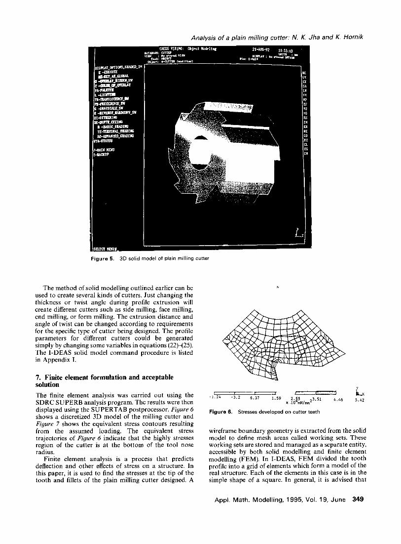
Figure 5. 30 solid model of plain milling cutter
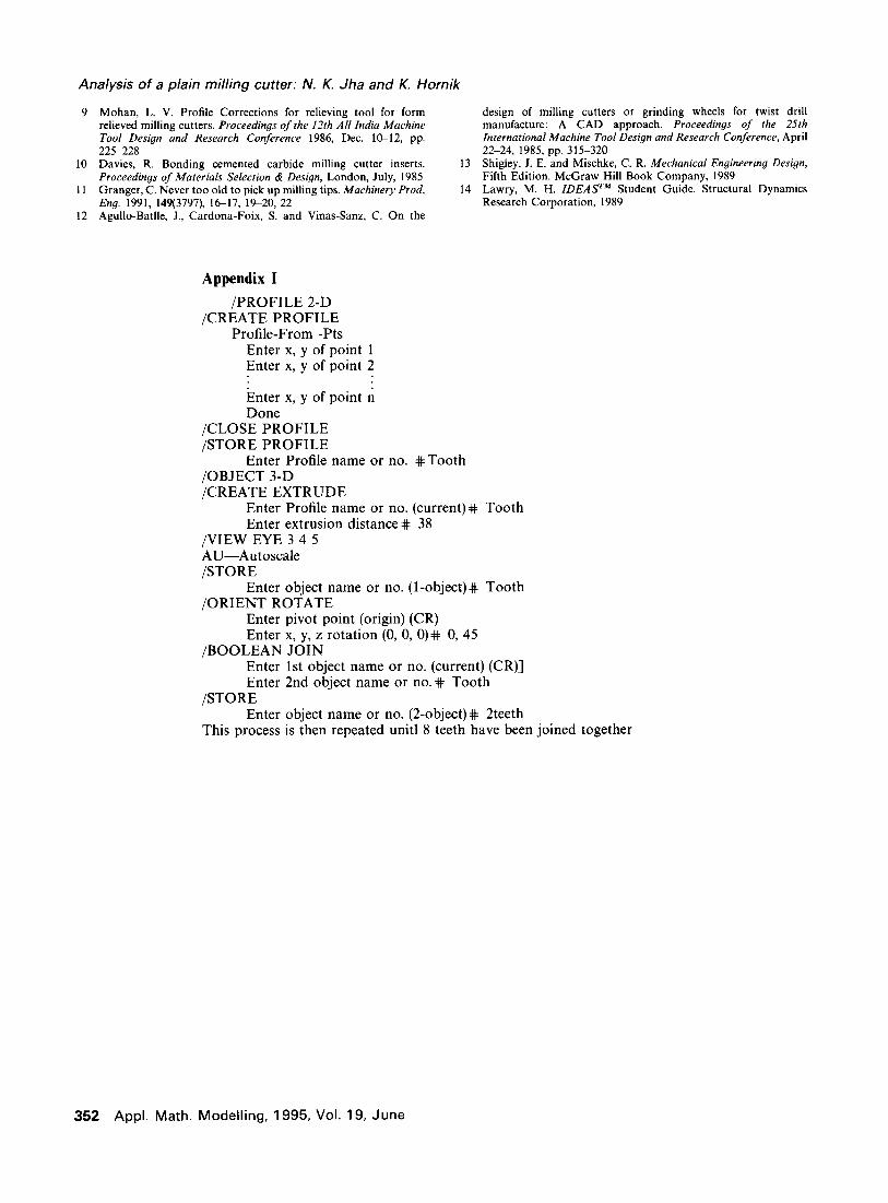
The method of solid modelling outlined earlier can be used to create several kinds of cutters. Just changing the thickness or twist angle during profile extrusion will create different cutters such as side milling, face milling, end milling, or form milling. The extrusion distance and angle of twist can be changed according to requirements for the specific type of cutter being designed. The profile parameters for different cutters could be generated simply by changing some variables in equations (22H25). The I-DEAS solid model command procedure is listed in Appendix I.
7. Finite element formulation and acceptable solution
The finite element analysis was carried out using the SDRC SUPERB analysis program. The results were then displayed using the SUPERTAB postprocessor. Figure 6 shows a discretized 3D model of the milling cutter and Figure 7 shows the equivalent stress contours resulting from the assumed loading. The equivalent stress trajectories of Figure 6 indicate that the highly stresses region of the cutter is at the bottom of the tool nose radius.
Finite element analysis is a process that predicts deflection and other effects of stress on a structure. In this paper, it is used to find the stresses at the tip of the tooth and fillets of the plain milling cutter designed. A
i I 1: -’ f r -1.24 -3.2 6.37 1.59
7. 2.25 3.51 10 nwm2
4.46 5.42
Figure 6. Stresses developed on cutter teeth
wireframe boundary geometry is extracted from the solid model to define mesh areas called working sets. These working sets are stored and managed as a separate entity, accessible by both solid modelling and finite element modelling (FEM). In I-DEAS, FEM divided the tooth profile into a grid of elements which form a model of the real structure. Each of the elements in this case is in the simple shape of a square. In general, it is advised that
Appl. Math. Modelling, 1995, Vol. 19, June 349

Analysis of a plain milling cutter: N. K. Jha and K. Hornik
x
Lx Figure 7. Mesh area creation
quadrilateral should be chosen over triangular element for structural models, since the quadrilateral element, having more degrees of freedom, can more accurately match the true displacement function. This is done automatically. In the FEM, the user has input information such as Young’s modulus to allow the governing equation to be developed in the form of a stiffness matrix. The unknowns for each element are the displacement at the “node” points at which the elements are connected. The finite element program of I-DEAS assembles the stiffness matrix for these simple elements together to form the global stiffness matrix for the entire model of the cutter. The stiffness matrix is solved for the unknown displacements, given the known forces and boundary conditions. This process is called preprocess- ing in I-DEAS. The solution phase is performed in I-DEAS module “model solution.” From the displace- ment of nodes, the stresses in each element are calculated.
In order to run a finite element analysis, it is necessary to determine the forces acting on the cutter. From the given conditions:
60,ooOH w=---
7zDn (26)
where H is the power, in kW, n is the speed, in rpm, and D is the diameter of the cutter. The stress calculation at the tip of the tooth of the cutter was done based on the concept of gear tooth stresses. The stress at each speed is determined by [ 131:
6wl O=s (27)
The maximum allowable stress at the tip of the cutter is determined to bei
(28)
where
S, (AGMA bending strength) = 44,000 psi K, (reliability factor) = 1 K, (life factor) = 1
It is advised in Ref. 13 that in case of a gear-blank temperature up to 250°F (12O”C), the temperature factor (KT) = 1.0. For higher temperatures, K, should be greater than unity. It is well known that at the tip of the cutter the temperature is higher than 250°F so the temperature factor, KT is assumed to be 1.2.
The ~allawable calculated from equation (28) is presented below. ~a,,owab,e = 43,140 psi for milling cutter. The tooth is supposed to act as a cantilever. To apply the finite element method for stress analysis of the tooth of the milling cutter, it is necessary to convert the continuum into a system with a finite number of unknowns so that the problem can be solved numerically. This procedure requires that
(1)
(2)
(3)
The tooth engaged in cutting is divided into finite elements by fictitious lines or surfaces. The elements are assumed to be interconnected at a discrete number of nodal points situated on the element boundaries. The displacement function, in terms of the nodal displacement field within each element, can be expressed as:
CKIWI = [WI (29)
where
K = stiffness matrix;
U = nodal displacement vector;
IV, = load vector.
A number of different programs are available in the market for FE analysis, such as NASTRAN, PATRAN, I-DEAS, and ANSYS. For this work, the I-DEAS software is used on IBM-RT workstations. The I-DEAS14 system only needs the solid model of the object and the size of the mesh areas to be generated. It creates the elements and nodal points automatically. It then generates its own stiffness matrix (K) and nodal displacement vector (V) by using information such as the modulus of elasticity, material thickness, and load vector (IV,) supplied by the user.
The mesh generated in this example had a global element length of 2 mm. Originally, a 1 mm element size was used, but this created too many nodes and elements and the resulting matrix was too large for the system to handle. The 2 mm size allowed the load be distributed over five nodal points. The mesh area created can be seen in Figure 7. The arrows in Figure 7 represent the displacement constraints.
The forces acting at the tip of the teeth are the tangential (w;,) and the radial (W,,) components of the cutting force. They are the force times the sine and cosine of the rake angle, respectively. The forces will change depending upon the material being milled. These are
350 Appl. Math. Modelling, 1995, Vol. 19, June

Analysis of a plain milling cutter: N. K. Jha and K. Hornik
Table 2. Cutter forces and stresses
CAEDS (maximum
n @pm) W (lb) WI WI (calcsated) shear
50 6403 6185 1657 48,896 87,500
100 3201 3092 829 24,438 43,000
500 640 619 166 4,888 8,750
1,000 320 309 83 2,444 4,370
2,000 160 154.5 41.5 1,222 2,190
calculated and given as input to I-DEAS and can be applied directly to the specifically chosen nodes.
I-DEAS determined the stresses on the tooth by utilizing the input forces and a material property table that has the modulus of elasticity of the tool material (cast steel). The element type chosen was thin shell. The analysis was run for various forces on the tooth. It is obvious that at different speeds the load will differ and in turn the stresses will differ. A study of stresses at various speeds was performed both by hand calculation and I-DEAS. The result is presented in Table 2.
There is a discrepancy between the stresses calculated and generated by I-DEAS. The reason for this discrepancy could be the fact that I-DEAS can calculate stresses at specific points, such as the fillets, while the hand calculation cannot show stress that exists at these points. The calculated stress indicates that at a speed of 50 rpm the stress on the cutter would exceed the maximum allowable stress (43,160 si), and the I-DEAS results agree. However, at 100 rpm, which is the optimum speed of the cutter, hand calculation and I-DEAS indicate that the stress is acceptable. All further discussions are related to this optimum speed.
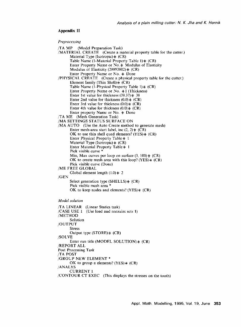
Finally I-DEAS shows the results of the stress distribution at different nodal points. The maximum and minimum stresses are printed out at differing critical points. Our main interest is the stress developing at the tip of the tool and at the fillets. It is obvious that stress concentrations are higher at these points. It was found that the stress developed at the tip of the cutting tool was higher than at the fillets. The stress values at the tip are shown in Table 2. The I-DEAS comman procedures used for FEM can be found in Appendix II. The fatigue factor due to alternating load of cutting has been included in the optimal design model and, due to this, the tool does not show any failure.
6. Discussion and conclusion
The main objective of this study has been to perform a detailed computer-aided design of a milling cutter by integrating solid modelling, optimization, and finite element analysis. Any cutter, single point or multiple point, can be designed based on the approach presented here. It could even be ventured that this approach can be used to design any complex mechanical component or system. Specifically for the cutter design, it produced the cutting variables that yield the minimum cost of manufacturing. The different design activities, such as
design, optimization, solid modelling, and finite element analysis, have been integrated. As is evident, the approach presented in this paper is flexible and easy to use. The cost parameter could not be compared due to lack of any similar work published in the literature.
Additionally, the study demonstrates that: (1) interactive modelling conveniently allows the designer to create, manipulawte, modify, store, assemble, analyze, and retrieve solid and 2D drawings from appropriate databases; (2) the use of the computers graphics and solid modelling in design of the cutter can greatly reduce the time taken from conception to completion. The time taken for the design, solid modelling, optimization, and finite element analysis can differ due to a change in hardware and software. However, it is clear that if there is a need to change the design due to a different requirement, the database of solid models needs to be changed; (3) the development of a complete mathemati- cal model including all possible real world constraints for the cutting tool has been demonstrated. The reduced gradient nonlinear program has been used to automate the design of a plain milling cutter; and (4) the stress at the optimum speed of the cutter is safe as indicated by I-DEAS print out.
Acknowledgment
The authors gratefully acknowledge the comments and suggestions of anonymous referees.
References
Kronenberg, M. Machining Science and Application. Pergamon Press, 1966 ASTME. Fundamentals of Tool Design, 1985 Draghici, G. and Paltinea, C. Calculation by convex mathematical programming of the optimal cutting condition when cylindrical milling. Int. J. Mach. Tool Des. Res. xxxx, 14, 143-160 Lee, S. J., Kapoor, S. G. and Devor, R. E. An Integrated Machining Process Design Simulator for Optimal Design of Face Milling System. Jha, N. K. Computer-aided multi-objective optimal design and finite element analysis of cutting tool. Proceedings of Manufactur- ing Internalional, 1990, 4, 59-70 Jha, N. K. and H.-H. Cheung. Computer-aided optimal design and finite element analysis of plain milling cutter. Proceedings oj the I989 ASME International Computers in Engineering Con-
ference & Exposition, 1989, 1, 511-521 Nelson, D. and Schaible, J. Updating boring and milling tools. Cutting Tool Eng. Aug. 1988,40(4), 32, 34, 37-38, 41 Smith, D. Reading the angles. Cuttina Tool Ena. Oct. 1990. 4217). 30, 32-33, 33 - -
”
Appl. Math. Modelling, 1995, Vol. 19, June 351
Analysis of a plain milling cutter: N. K. Jha and K. Hornik
9 Mohan, L. V. Profile Corrections for relieving tool for form relieved milling cutters. Proceedings of the 12th All India Machine Tool Design and Research Conference 1986, Dec. l&12, pp. 2255228
10 Davies, R. Bonding cemented carbide milling cutter inserts. Proceedings of Materials Selection & Design, London, July, 1985
11 Granger, C. Never too old to pick up milling tips. Machinery Prod, Eng. 1991,149(3797), 1617, 19-20, 22
12 Agullo-Bathe, J., Cardona-Foix, S. and Vinas-Sanz, C. On the
design of milling cutters or grinding wheels for twist drill manufacture: A CAD approach. Proceedings of the 25th International Machine Tool Design and Research Conference, April 22-24, 1985, pp. 315-320
13 Shigley, J. E. and Mischke, C. R. Mechanical Engineering Design, Fifth Edition. McGraw Hill Book Company, 1989
14 Lawry, M. H. IDEAS TM Student Guide. Structural Dynamics Research Corporation, 1989
Appendix I
/PROFILE 2-D /CREATE PROFILE
Profile-From -Pts Enter x, y of point 1 Enter x, y of point 2
Enter x, y of point n Done
/CLOSE PROFILE /STORE PROFILE
Enter Profile name or no. #Tooth /OBJECT 3-D /CREATE EXTRUDE
Enter Profile name or no. (current)# Tooth Enter extrusion distance# 38
/VIEW EYE 3 4 5 AU-Autoscale /STORE
Enter object name or no. (l-object)# Tooth /ORIENT ROTATE
Enter pivot point (origin) (CR) Enter x, y, z rotation (0, 0, 0)# 0, 45
/BOOLEAN JOIN Enter 1st object name or no. (current) (CR)] Enter 2nd object name or no.+ Tooth
/STORE Enter object name or no. (Zobject)# 2teeth
This process is then repeated unit1 8 teeth have been joined together
352 Appl. Math. Modelling, 1995, Vol. 19, June
Analysis of a plain milling cutter: N. K. Jha and K. Hornik
Appendix II
Preprocessing
/TA MP (Model Preparation Task) /MATERIAL CREATE (Create a material property table for the cutter.)
Material Type (Isotropic) # (CR) Table Name (l-Material Property Table l)# (CR) Enter Property Name or No.# Modulus of Elasticity Modulus of Elasticity (29993802)# (CR) Enter Property Name or No. # Done
/PHYSICAL CREATE (Create a physical property table for the cutter.) Element family (Thin Shell)+ (CR) Table Name (l-Physical Property Table 1) # (CR) Enter Property Name or No. # 1 (Thickness) Enter 1st value for thickness (39.37)# 38 Enter 2nd value for thickness (O.O)# (CR) Enter 3rd value for thickness (O.O)# (CR) Enter 4th value for thickness (O.O)# (CR) Enter property Name or No. # Done
/TA ME (Mesh Generation Task) /MA SETTINGS STATUS SURFACE ON /MA AUTO (Use the Auto Create method to generate mesh)
Enter mesh-area start label, inc (2, 2)# (CR) OK to use thin shell quad elements? (YES)# (CR) Enter Physical Property Table# 1 Material Type (Isotropic) # (CR) Enter Material Property Table# 1 Pick visible curve * Min, Max curves per loop on surface (3, lOO)# (CR) OK to create mesh area with this loop? (YES)# (CR) Pick visible curve (Done)
/ME FREE GLOBAL Global element length (l.O)# 2
/GEN Select generation type (SHELLS)# (CR) Pick visible mesh area * OK to keep nodes and elements? (YES)# (CR)
Model solution
/TA LINEAR (Linear Statics task) /CASE USE 1 (Use load and restraint sets 1) /METHOD
Solution /OUTPUT
Stress Output type (STORE)# (CR)
/SOLVE Enter run title (MODEL SOLUTION)# (CR)
/REPORT ALL Post Processing Task /TA POST /GROUP NEW ELEMENT *
OK to group n elements? (YES)+ (CR) /ANALYS
CURRENT 1 /CONTOUR CT EXEC (This displays the stresses on the tooth)
Appl. Math. Modelling, 1995, Vol. 19, June 353