Embed Size (px)
Citation preview

INTEGRATED CIRCUITS, SILICON MONOLITHIC, HCMOS DUAL D-TYPE FLIP-FLOP WITH PRESET AND CLEAR
AND FULLY BUFFERED OUTPUTS
BASED ON TYPE 54HCT74
ESCC Detail Specification No. 9203/070
Issue 5 May 2019
Document Custodian: European Space Agency – see https://escies.org
Page 1 of 20

ESCC Detail Specification
No. 9203/070
PAGE 2
ISSUE 5
LEGAL DISCLAIMER AND COPYRIGHT
European Space Agency, Copyright © 2019. All rights reserved.
The European Space Agency disclaims any liability or responsibility, to any person or entity, with respect to any loss or damage caused, or alleged to be caused, directly or indirectly by the use and application of this ESCC publication.
This publication, without the prior permission of the European Space Agency and provided that it is not used for a commercial purpose, may be:
− copied in whole, in any medium, without alteration or modification. − copied in part, in any medium, provided that the ESCC document identification, comprising the
ESCC symbol, document number and document issue, is removed.

ESCC Detail Specification
No. 9203/070
PAGE 3
ISSUE 5
DOCUMENTATION CHANGE NOTICE
(Refer to https://escies.org for ESCC DCR content)
DCR No. CHANGE DESCRIPTION
1184 1200 1258 Specification upissued to incorporate changes per DCR.

ESCC Detail Specification
No. 9203/070
PAGE 4
ISSUE 5
TABLE OF CONTENTS
1 GENERAL 5
1.1 SCOPE 5
1.2 APPLICABLE DOCUMENTS 5
1.3 TERMS, DEFINITIONS, ABBREVIATIONS, SYMBOLS AND UNITS 5
1.4 THE ESCC COMPONENT NUMBER AND COMPONENT TYPE VARIANTS 5
1.4.1 The ESCC Component Number 5
1.4.2 Component Type Variants 5
1.5 MAXIMUM RATINGS 6
1.6 HANDLING PRECAUTIONS 6
1.7 PHYSICAL DIMENSIONS AND TERMINAL IDENTIFICATION 7
1.7.1 Flat Package (FP) - 14 Pin 7
1.7.2 Dual-in-line Package (DIP) - 14 Pin 8
1.7.3 Notes to Para. 1.7 Physical Dimensions and Terminal Identification 9
1.8 FUNCTIONAL DIAGRAM 9
1.9 PIN ASSIGNMENT 9
1.10 TRUTH TABLE 10
1.11 PROTECTION NETWORKS 10
2 REQUIREMENTS 10
2.1 GENERAL 10
2.1.1 Deviations from the Generic Specification 11
2.2 MARKING 11
2.3 ELECTRICAL MEASUREMENTS AT ROOM, HIGH AND LOW TEMPERATURES 11
2.3.1 Room Temperature Electrical Measurements 11
2.3.2 High and Low Temperatures Electrical Measurements 14
2.3.3 Notes to Electrical Measurement Tables 15
2.4 PARAMETER DRIFT VALUES 16
2.5 INTERMEDIATE AND END-POINT ELECTRICAL MEASUREMENTS 16
2.6 HIGH TEMPERATURE REVERSE BIAS BURN-IN CONDITIONS 17
2.6.1 N-Channel HTRB 17
2.6.2 P-Channel HTRB 17
2.7 POWER BURN-IN CONDITIONS 18
2.8 OPERATING LIFE CONDITIONS 18
2.9 TOTAL DOSE RADIATION TESTING 18
2.9.1 Bias Conditions and Total Dose Level for Total Dose Radiation Testing 18
2.9.2 Electrical Measurements for Total Dose Radiation Testing 19
APPENDIX ‘A’ 20

ESCC Detail Specification
No. 9203/070
PAGE 5
ISSUE 5
1 GENERAL
1.1 SCOPE This specification details the ratings, physical and electrical characteristics and test and inspection data for the component type variants and/or the range of components specified below. It supplements the requirements of, and shall be read in conjunction with, the ESCC Generic Specification listed under Applicable Documents.
1.2 APPLICABLE DOCUMENTS The following documents form part of this specification and shall be read in conjunction with it:
(a) ESCC Generic Specification No. 9000. (b) MIL-STD-883, Test Methods and Procedures for Microelectronics.
1.3 TERMS, DEFINITIONS, ABBREVIATIONS, SYMBOLS AND UNITS For the purpose of this specification, the terms, definitions, abbreviations, symbols and units specified in ESCC Basic Specification No. 21300 shall apply.
1.4 THE ESCC COMPONENT NUMBER AND COMPONENT TYPE VARIANTS
1.4.1 The ESCC Component Number The ESCC Component Number shall be constituted as follows:
Example: 920307001F
• Detail Specification Reference: 9203070 • Component Type Variant Number: 01 (as required) • Total Dose Radiation Level Letter: F (as required)
1.4.2 Component Type Variants The component type variants applicable to this specification are as follows:
Variant Number
Based on Type Case Terminal Material and Finish
Weight max g
Total Dose Radiation Level Letter
01 54HCT74 FP G2 0.7 F [50kRAD(Si)]
02 54HCT74 FP G4 0.7 F [50kRAD(Si)]
03 54HCT74 DIP G2 2.2 F [50kRAD(Si)]
04 54HCT74 DIP G4 2.2 F [50kRAD(Si)]
The terminal material and finish shall be in accordance with the requirements of ESCC Basic Specification No. 23500.
The total dose radiation level letter shall be as defined in ESCC Basic Specification No. 22900. If an alternative radiation test level is specified in the Purchase Order the letter shall be changed accordingly.

ESCC Detail Specification
No. 9203/070
PAGE 6
ISSUE 5
1.5 MAXIMUM RATINGS
The maximum ratings shall not be exceeded at any time during use or storage.
Maximum ratings shall only be exceeded during testing to the extent specified in this specification and when stipulated in Test Methods and Procedures of the ESCC Generic Specification.
Characteristics Symbols Maximum Ratings Units Remarks
Supply Voltage VDD -0.5 to 7 V Note 1
Input Voltage VIN -0.5 to VDD+0.5 V Notes 1, 2
Output Voltage VOUT -0.5 to VDD+0.5 V Notes 1, 3
Device Power Dissipation (Continuous)
PD 275 mW Note 4
Supply Current IDDop 50 mA
Operating Temperature Range Top -55 to +125 °C Tamb
Storage Temperature Range Tstg -65 to +150 °C
Soldering Temperature Tsol +265 °C Note 5
NOTES: 1. Device is functional for 4.5V ≤ VDD ≤ 5.5V. 2. Input current limited to IIC = ±20mA. 3. Output current limited to IOUT = ±25mA. 4. The maximum device dissipation is determined by IDDop max (50mA) × 5.5V. 5. Duration 10 seconds maximum at a distance of not less than 1.5mm from the device body
and the same terminal shall not be resoldered until 3 minutes have elapsed.
1.6 HANDLING PRECAUTIONS These devices are susceptible to damage by electrostatic discharge. Therefore, suitable precautions shall be employed for protection during all phases of manufacture, testing, packaging, shipment and any handling.
These components are categorised as Class 2 per ESCC Basic Specification No. 23800 with a Minimum Critical Path Failure Voltage of 2500 Volts.

ESCC Detail Specification
No. 9203/070
PAGE 7
ISSUE 5
1.7 PHYSICAL DIMENSIONS AND TERMINAL IDENTIFICATION
Consolidated Notes are given in Para. 1.7.3.
1.7.1 Flat Package (FP) - 14 Pin
Symbols Dimensions mm Notes
Min Max
A 6.75 7.06
B 9.76 10.14
C 1.49 1.95
D 0.1 0.15 5
E 7.5 7.75
F 1.27 BSC 3, 6
G 0.38 0.48 5
H 6 - 5
L 18.75 22
M 0.33 0.43
N 4.32 TYPICAL

ESCC Detail Specification
No. 9203/070
PAGE 8
ISSUE 5
1.7.2 Dual-in-line Package (DIP) - 14 Pin
Symbols Dimensions mm Notes
Min Max
A 2.1 2.54
a1 3 3.7
a2 0.63 1.14 2
B 1.82 2.23
b 0.4 0.5 5
b1 1.27 TYPICAL 5
c 0.2 0.3 5
D 18.79 19.2
E 7.36 7.87
e 2.54 BSC 4, 6
e1 15.11 15.37
e2 7.62 8.12
F 7.11 7.75
I - 3.7
K 10.9 12.1

ESCC Detail Specification
No. 9203/070
PAGE 9
ISSUE 5
1.7.3 Notes to Para. 1.7 Physical Dimensions and Terminal Identification
1. Index area; a notch or a dot shall be located adjacent to Pin 1 and shall be within the shaded area shown. For chip carrier packages, the index shall be as shown.
2. The dimension shall be measured from the seating plane to the base plane. 3. The true position pin spacing is 1.27mm between centrelines. Each pin centreline shall be
located within ±0.13mm of its true longitudinal position relative to Pin 1 and the highest pin number.
4. The true position pin spacing is 2.54mm between centrelines. Each pin centreline shall be located within ±0.25mm of its true longitudinal position relative to Pin 1 and the highest pin number.
5. All terminals. 6. 12 spaces. 9. For all pins, either pin shape may be supplied.
1.8 FUNCTIONAL DIAGRAM
NOTES: 1. The package lid for all packages is not connected to any terminal.
1.9 PIN ASSIGNMENT Pin Function Pin Function
1 1CLR Input (Clear) 8 2Q Output
2 1D Input 9 2Q Output
3 1CLK Input (Clock) 10 2PRE Input (Preset)
4 1PRE Input (Preset) 11 2CLK Input (Clock)
5 1Q Output 12 2D Input
6 1Q Output 13 2CLR Input (Clear)
7 VSS 14 VDD

ESCC Detail Specification
No. 9203/070
PAGE 10
ISSUE 5
1.10 TRUTH TABLE
1. Logic Level Definitions: L = Low Level, H = High Level, X = Irrelevant. 2. ↑ = Transition, Low to High; ↓ = Transition, High to Low. 3. Q0 or Q0: The Level of Q or Q before the indicated steady-state input conditions are
established.
EACH FLIP-FLOP
INPUTS OUTPUTS FUNCTION
CLR PRE D CLK Q Q
L H X X L H Clear
H L X X H L Preset
L L X X H H -
H H L ↑ L H -
H H H ↑ H L -
H H X ↓ Q0 Q0 No Change
1.11 PROTECTION NETWORKS
2 REQUIREMENTS
2.1 GENERAL The complete requirements for procurement of the components specified herein are as stated in this specification and the ESCC Generic Specification. Permitted deviations from the Generic Specification, applicable to this specification only, are listed below.
Permitted deviations from the Generic Specification and this Detail Specification, formally agreed with specific Manufacturers on the basis that the alternative requirements are equivalent to the ESCC requirement and do not affect the component’s reliability, are listed in the appendices attached to this specification.
ESCC Detail Specification
No. 9203/070
PAGE 11
ISSUE 5
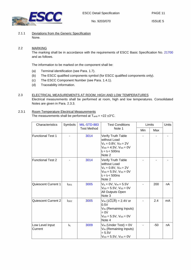
2.1.1 Deviations from the Generic Specification
None.
2.2 MARKING The marking shall be in accordance with the requirements of ESCC Basic Specification No. 21700 and as follows.
The information to be marked on the component shall be:
(a) Terminal identification (see Para. 1.7). (b) The ESCC qualified components symbol (for ESCC qualified components only). (c) The ESCC Component Number (see Para. 1.4.1). (d) Traceability information.
2.3 ELECTRICAL MEASUREMENTS AT ROOM, HIGH AND LOW TEMPERATURES Electrical measurements shall be performed at room, high and low temperatures. Consolidated Notes are given in Para. 2.3.3.
2.3.1 Room Temperature Electrical Measurements The measurements shall be performed at Tamb = +22 ±3°C.
Characteristics Symbols MIL-STD-883 Test Method
Test Conditions Note 1
Limits Units
Min Max
Functional Test 1 - 3014 Verify Truth Table without Load VIL = 0.8V, VIH = 2V VDD = 4.5V, VSS = 0V tr = tf < 500ns Note 2
- - -
Functional Test 2 - 3014 Verify Truth Table without Load VIL = 0.8V, VIH = 2V VDD = 5.5V, VSS = 0V tr = tf < 500ns Note 2
- - -
Quiescent Current 1 IDD1 3005 VIL = 0V, VIH = 5.5V VDD = 5.5V, VSS = 0V All Outputs Open Note 3
- 200 nA
Quiescent Current 2 IDD2 3005 VIN (1CLR) = 2.4V or 0.5V VIN (Remaining Inputs) = 0V VDD = 5.5V, VSS = 0V Note 4
- 2.4 mA
Low Level Input Current
IIL 3009 VIN (Under Test) = 0V VIN (Remaining Inputs) = 5.5V VDD = 5.5V, VSS = 0V
- -50 nA

ESCC Detail Specification
No. 9203/070
PAGE 12
ISSUE 5
Characteristics Symbols MIL-STD-883
Test Method Test Conditions
Note 1 Limits Units
Min Max
High Level Input Current
IIH 3010 VIN (Under Test) = 5.5V VIN (Remaining Inputs) = 0V VDD = 5.5V, VSS = 0V
- 50 nA
Low Level Output Voltage 1
VOL1 3007 VIL = 0.8V, VIH = 2V, IOL = 20µA VDD = 4.5V, VSS = 0V
- 100 mV
Low Level Output Voltage 2
VOL2 3007 VIL = 0.8V, VIH = 2V, IOL = 4mA VDD = 4.5V, VSS = 0V
- 260 mV
High Level Output Voltage 1
VOH1 3006 VIL = 0.8V, VIH = 2V, IOH = -20µA VDD = 4.5V, VSS = 0V
4.4 - V
High Level Output Voltage 2
VOH2 3006 VIL = 0.8V, VIH = 2V, IOH = -4mA VDD = 4.5V, VSS = 0V
3.98 - V
Threshold Voltage N-Channel
VTHN - 1CLR Input at Ground All Other Inputs: VIN = 5V VDD = 5V, ISS = -10µA
-0.25 -1.45 V
Threshold Voltage P-Channel
VTHP - 1D Input at Ground All Other Inputs: VIN = -5V VSS = -5V, IDD = 10µA
0.45 1.85 V
Input Clamp Voltage 1, to VSS
VIC1 - IIN (Under Test) = -100µA VDD = Open, VSS = 0V All Other Pins Open
-400 -900 mV
Input Clamp Voltage 2, to VDD
VIC2 - IIN (Under Test) = 100µA VDD = 0V, VSS = Open All Other Pins Open
400 900 mV
Input Capacitance CIN 3012 VIN (Not Under Test) = 0V VDD = VSS = 0V f = 100kHz to 1MHz Note 5
- 10 pF
Propagation Delay Low to High 1, CLK to Q and Q
tPLH1 3003 VIN (Under Test) = Pulse Generator VIN (Remaining Inputs) = Truth Table VIL = 0V, VIH = 4.5V VDD = 4.5V, VSS = 0V Note 6
- 35 ns

ESCC Detail Specification
No. 9203/070
PAGE 13
ISSUE 5
Characteristics Symbols MIL-STD-883
Test Method Test Conditions
Note 1 Limits Units
Min Max
Propagation Delay High to Low 1, CLK to Q and Q
tPHL1 3003 VIN (Under Test) = Pulse Generator VIN (Remaining Inputs) = Truth Table VIL = 0V, VIH = 4.5V VDD = 4.5V, VSS = 0V Note 6
- 35 ns
Propagation Delay Low to High 2, CLR to Q
tPLH2 3003 VIN (Under Test) = Pulse Generator VIN (Remaining Inputs) = Truth Table VIL = 0V, VIH = 4.5V VDD = 4.5V, VSS = 0V Note 6
- 46 ns
Propagation Delay High to Low 2, CLR to Q
tPHL2 3003 VIN (Under Test) = Pulse Generator VIN (Remaining Inputs) = Truth Table VIL = 0V, VIH = 4.5V VDD = 4.5V, VSS=0V Note 6
- 46 ns
Propagation Delay Low to High 3, PRE to Q
tPLH3 3003 VIN (Under Test) = Pulse Generator VIN (Remaining Inputs) = Truth Table VIL = 0V, VIH = 4.5V VDD = 4.5V, VSS = 0V Note 6
- 46 ns
Propagation Delay High to Low 3, PRE to Q
tPHL3 3003 VIN (Under Test) = Pulse Generator VIN (Remaining Inputs) = Truth Table VIL = 0V, VIH = 4.5V VDD = 4.5V, VSS = 0V Note 6
- 46 ns
Transition Time Low to High
tTLH 3004 VIN (Under Test) = Pulse Generator VIN (Remaining Inputs) = Truth Table VIL = 0V, VIH = 4.5V VDD = 4.5V, VSS = 0V Note 6
- 15 ns
Transition Time High to Low
tTHL 3004 VIN (Under Test) = Pulse Generator VIN (Remaining Inputs) = Truth Table VIL = 0V, VIH = 4.5V VDD = 4.5V, VSS = 0V Note 6
- 15 ns

ESCC Detail Specification
No. 9203/070
PAGE 14
ISSUE 5
Characteristics Symbols MIL-STD-883
Test Method Test Conditions
Note 1 Limits Units
Min Max
Maximum Clock Frequency
fCLK - CLK = Pulse Generator VIL = 0V, VIH = 4.5V VDD = 4.5V, VSS = 0V Notes 7, 8
27 - MHz
2.3.2 High and Low Temperatures Electrical Measurements The measurements shall be performed at Tamb = +125 (+0 -5)°C and Tamb = -55 (+5 -0)°C.
Characteristics Symbols MIL-STD-883 Test Method
Test Conditions Note 1
Limits Units
Min Max
Functional Test 1 - 3014 Verify Truth Table without Load VIL = 0.8V, VIH = 2V VDD = 4.5V, VSS = 0V tr = tf < 500ns Note 2
- - -
Functional Test 2 - 3014 Verify Truth Table without Load VIL = 0.8V, VIH = 2V VDD = 5.5V, VSS = 0V tr = tf < 500ns Note 2
- - -
Quiescent Current 1 IDD1 3005 VIL = 0V, VIH = 5.5V VDD = 5.5V, VSS = 0V All Outputs Open Note 3
- 4 µA
Quiescent Current 2 IDD2 3005 VIN (1CLR) = 2.4V or 0.5V VIN (Remaining Inputs) = 0V VDD = 5.5V, VSS = 0V Note 4
- 3 mA
Low Level Input Current
IIL 3009 VIN (Under Test) = 0V VIN (Remaining Inputs)=5.5V VDD=5.5V,VSS=0V
- -1 µA
High Level Input Current
IIH 3010 VIN (Under Test)=5.5V VIN (Remaining Inputs) = 0V VDD = 5.5V, VSS = 0V
- 1 µA
Low Level Output Voltage 1
VOL1 3007 VIL = 0.8V, VIH = 2V, IOL = 20µA VDD = 4.5V, VSS = 0V
- 100 mV
Low Level Output Voltage 2
VOL2 3007 VIL = 0.8V, VIH = 2V, IOL = 4mA VDD = 4.5V, VSS = 0V
- 400 mV
High Level Output Voltage 1
VOH1 3006 VIL = 0.8V, VIH = 2V, IOH = -20µA VDD = 4.5V, VSS = 0V
4.4 - V

ESCC Detail Specification
No. 9203/070
PAGE 15
ISSUE 5
Characteristics Symbols MIL-STD-883
Test Method Test Conditions
Note 1 Limits Units
Min Max
High Level Output Voltage 2
VOH2 3006 VIL = 0.8V, VIH = 2V, IOH = -4mA VDD = 4.5V, VSS = 0V
3.7 - V
Input Clamp Voltage 1, to VSS
VIC1 - IIN (Under Test) = -100µA VDD = Open, VSS = 0V All Other Pins Open
-0.1 -1.2 V
Input Clamp Voltage 2, to VDD
VIC2 - IIN (Under Test) = 100µA VDD = 0V, VSS = Open All Other Pins Open
0.1 1.2 V
2.3.3 Notes to Electrical Measurement Tables 1. Unless otherwise specified all inputs and outputs shall be tested for each characteristic,
inputs not under test shall be VIN = VSS or VDD and outputs not under test shall be open. 2. Functional tests shall be performed with f = 10kHz (min). The maximum time to output
comparator strobe = 30µs. 3. Quiescent Current 1 shall be tested using the following input conditions:
(a) 1CLR = 2CLR = VIH; all other inputs = VIL (b) 1PRE = 2PRE = VIH; all other inputs = VIL
4. Quiescent Current 2 shall be tested using the following input conditions: (a) 1CLR = 2.4V; all other inputs = 0V (b) 1CLR = 0.5V; all other inputs = 0V
5. Guaranteed but not tested. 6. Measurements shall be performed as a go-no-go test on a 100% basis. Read and record
measurements shall be performed on a sample of 5 components. The pulse generator shall have the following characteristics: VGEN = 0 to VDD; fGEN = 1MHz minimum; tr and tf ≤ 6ns (10% to 90%); duty cycle = 50%; Zout = 50Ω. Output load capacitance CL = 50pF ±5% including scope probe, wiring and stray capacitance without component in the test fixture and output load resistance RL = 1kΩ ±5%. Propagation delay shall be measured referenced to the 50% input and output voltages. Transition time shall be measured referenced to the 10% and 90% output voltage.
7. Read and record measurements shall be performed on a sample of 5 components with 0 failures permitted.
8. A pulse, having the following conditions, shall be applied to the clock input: VP = 0V to VDD. Maximum clock frequency fCLK requirement shall be considered as met if proper output state changes occur with the pulse repetition rate set to that given in the Limits column.
ESCC Detail Specification
No. 9203/070
PAGE 16
ISSUE 5
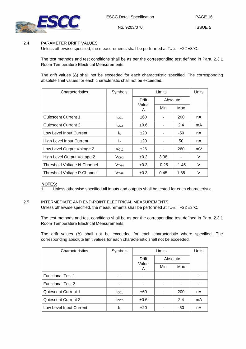
2.4 PARAMETER DRIFT VALUES
Unless otherwise specified, the measurements shall be performed at Tamb = +22 ±3°C.
The test methods and test conditions shall be as per the corresponding test defined in Para. 2.3.1 Room Temperature Electrical Measurements.
The drift values (Δ) shall not be exceeded for each characteristic specified. The corresponding absolute limit values for each characteristic shall not be exceeded.
Characteristics Symbols Limits Units
Drift Value
Δ
Absolute
Min Max
Quiescent Current 1 IDD1 ±60 - 200 nA
Quiescent Current 2 IDD2 ±0.6 - 2.4 mA
Low Level Input Current IIL ±20 - -50 nA
High Level Input Current IIH ±20 - 50 nA
Low Level Output Voltage 2 VOL2 ±26 - 260 mV
High Level Output Voltage 2 VOH2 ±0.2 3.98 - V
Threshold Voltage N-Channel VTHN ±0.3 -0.25 -1.45 V
Threshold Voltage P-Channel VTHP ±0.3 0.45 1.85 V
NOTES: 1. Unless otherwise specified all inputs and outputs shall be tested for each characteristic.
2.5 INTERMEDIATE AND END-POINT ELECTRICAL MEASUREMENTS Unless otherwise specified, the measurements shall be performed at Tamb = +22 ±3°C.
The test methods and test conditions shall be as per the corresponding test defined in Para. 2.3.1 Room Temperature Electrical Measurements.
The drift values (Δ) shall not be exceeded for each characteristic where specified. The corresponding absolute limit values for each characteristic shall not be exceeded.
Characteristics Symbols Limits Units
Drift Value
Δ
Absolute
Min Max
Functional Test 1 - - - - -
Functional Test 2 - - - - -
Quiescent Current 1 IDD1 ±60 - 200 nA
Quiescent Current 2 IDD2 ±0.6 - 2.4 mA
Low Level Input Current IIL ±20 - -50 nA

ESCC Detail Specification
No. 9203/070
PAGE 17
ISSUE 5
Characteristics Symbols Limits Units
Drift Value
Δ
Absolute
Min Max
High Level Input Current IIH ±20 - 50 nA
Low Level Output Voltage 2 VOL2 ±26 - 260 mV
High Level Output Voltage 2 VOH2 ±0.2 3.98 - V
Threshold Voltage N-Channel VTHN ±0.3 -0.25 -1.45 V
Threshold Voltage P-Channel VTHP ±0.3 0.45 1.85 V
NOTES: 1. Unless otherwise specified all inputs and outputs shall be tested for each characteristic. 2. The drift values (Δ) are applicable to the Operating Life test only.
2.6 HIGH TEMPERATURE REVERSE BIAS BURN-IN CONDITIONS
2.6.1 N-Channel HTRB Characteristics Symbols Test Conditions Units
Ambient Temperature Tamb +125 (+0 -5) °C
Outputs 1Q, 1Q , 2Q, 2Q VOUT Open or VSS V
Inputs CLR, D, CLK, PRE (all gates)
VIN VSS V
Positive Supply Voltage VDD 5.5 (+0 -0.5) V
Negative Supply Voltage VSS 0 V
Duration t 72 Hours
NOTES: 1. Input Protection Resistor = 680Ω min to 47kΩ max. 2. Output Load = 1kΩ min to 10kΩ max.
2.6.2 P-Channel HTRB Characteristics Symbols Test Conditions Units
Ambient Temperature Tamb +125 (+0 -5) °C
Outputs 1Q, 1Q , 2Q, 2Q VOUT Open or VDD V
Inputs CLR, D, CLK, PRE (all gates)
VIN VDD V
Positive Supply Voltage VDD 5.5 (+0 -0.5) V
Negative Supply Voltage VSS 0 V
Duration t 72 Hours
NOTES: 1. Input Protection Resistor = 680Ω min to 47kΩ max. 2. Output Load = 1kΩ min to 10kΩ max.

ESCC Detail Specification
No. 9203/070
PAGE 18
ISSUE 5
2.7 POWER BURN-IN CONDITIONS
Characteristics Symbols Test Conditions Units
Ambient Temperature Tamb +125 (+0 -5) °C
Outputs 1Q, 1Q , 2Q, 2Q VOUT VDD V
Inputs 1CLR, 2CLR, 1PRE, 2PRE VIN VDD V
Inputs 1CLK, 2CLK VIN VGEN1 V
Inputs 1D, 2D VIN VGEN2 V
Pulse Voltage VGEN 0V to VDD V
Pulse Frequency Square Wave fGEN1 fGEN2
100k ±10% 50k ±10%
50 ±15% Duty Cycle tr = tf ≤ 400ns
Hz
Positive Supply Voltage VDD 5.5 (+0 -0.5) V
Negative Supply Voltage VSS 0 V
NOTES: 1. Input Protection Resistor = 680Ω min to 47kΩ max. 2. Output Load = 1kΩ min to 10kΩ max.
2.8 OPERATING LIFE CONDITIONS The conditions shall be as specified in Para. 2.7 Power Burn-in.
2.9 TOTAL DOSE RADIATION TESTING
2.9.1 Bias Conditions and Total Dose Level for Total Dose Radiation Testing Continuous bias shall be applied during irradiation testing as specified below.
The total dose level applied shall be as specified in Para. 1.4.2 or in the Purchase Order.
Characteristics Symbols Test Conditions Units
Ambient Temperature Tamb +22 ±3 °C
Outputs 1Q, 1Q, 2Q, 2Q VOUT Open V
Inputs 1CLR, 2CLR VIN VSS V
Inputs D, CLK, PRE (all gates) VIN VDD V
Positive Supply Voltage VDD 5.5 ±0.3 V
Negative Supply Voltage VSS 0 V
NOTES: 1. Input Protection Resistor = 680Ω min to 47kΩ max.

ESCC Detail Specification
No. 9203/070
PAGE 19
ISSUE 5
2.9.2 Electrical Measurements for Total Dose Radiation Testing
Prior to irradiation testing the devices shall have successfully met Para. 2.3.1 Room Temperature Electrical Measurements specified herein.
Unless otherwise stated the measurements shall be performed at Tamb = +22 ±3°C.
The test methods and test conditions shall be as per the corresponding test defined in Para. 2.3.1 Room Temperature Electrical Measurements.
The parameters to be measured during and on completion of irradiation testing are shown below.
Unless otherwise specified all inputs and outputs shall be tested for each characteristic.
Characteristics Symbols Limits Units
Drift Value
Δ
Absolute
Min Max
Quiescent Current 1 IDD1 - - 20 µA
Threshold Voltage N-Channel VTHN ±0.6 -0.2 -1.5 V
Threshold Voltage P-Channel VTHP ±0.6 0.7 2.2 V

ESCC Detail Specification
No. 9203/070
PAGE 20
ISSUE 5
APPENDIX ‘A’
AGREED DEVIATIONS FOR STMICROELECTRONICS (F)
ITEMS AFFECTED DESCRIPTION OF DEVIATIONS
Para. 2.1.1 Deviations from the Generic Specification: Deviations from Production Control - Chart F2
Total Dose Radiation Testing: The following deviation from the procedures for qualification and procurement lot acceptance in ESCC Basic Specification No. 22900 shall apply: The radiation exposure and test sequence requirements including radiation levels, time intervals for measurement, and the flow chart for qualification and lot acceptance testing, may be replaced by the requirements of ST radiation test procedure 0043082.
Para. 2.1.1 Deviations from the Generic Specification: Deviations from Screening Tests - Chart F3
External Visual Inspection: The criteria applicable to chip-outs are those described in MIL-STD-883, Test Method 2009, Paras 3.3.6(b) and 3.3.7(a).
High Temperature Reverse Bias Burn-in: The temperature limits of MIL-STD-883, Para. 4.5.8(c) may be used.
Power Burn-in test is performed using STMicroelectronics Specification Ref: 0019255.
Solderability is not applicable unless specifically stipulated in the Purchase Order.
Para. 2.1.1 Deviations from the Generic Specification: Deviations from Qualification and Periodic Tests - Chart F4
External Visual Inspection: The criteria applicable to chip-outs are those described in MIL-STD-883, Test Method 2009, Paras 3.3.6(b) and 3.3.7(a).
Operating Life: The temperature limits of MIL-STD-883, Para. 4.5.8(c) may be used.
Para. 2.3.1 Room Temperature Electrical Measurements
All AC characteristics (Capacitance and Timings) may be considered guaranteed but not tested if successful pilot lot testing has been performed on the wafer lot which includes AC characteristic measurements per the Detail Specification.
A summary of the pilot lot testing shall be provided if required by the Purchase Order.
Para. 2.3.2 High and Low Temperatures Electrical Measurements
High and Low Temperatures Electrical Measurements may be considered guaranteed but not tested if successful pilot lot testing has been performed on the wafer lot which includes High and Low Temperatures Electrical Measurements per the Detail Specification.
A summary of the pilot lot testing shall be provided if required by the Purchase Order.


![Monolithic silicon-photonic platforms in state-of-the-art ... · Monolithic silicon-photonic platforms in state-of-the-art CMOS SOI processes [Invited] VLADIMIR STOJANOVIC´,1,2,*](https://img.dokumen.tips/doc/110x75/60a637b0c73a7d69b73b52dd/monolithic-silicon-photonic-platforms-in-state-of-the-art-monolithic-silicon-photonic.jpg)