Embed Size (px)
Citation preview

Missouri University of Science and Technology Missouri University of Science and Technology
Scholars' Mine Scholars' Mine
International Conference on Case Histories in Geotechnical Engineering
(2008) - Sixth International Conference on Case Histories in Geotechnical Engineering
14 Aug 2008, 4:30pm - 6:00pm
Integrated Approach for Stabilisation of Varunavat Parvat Integrated Approach for Stabilisation of Varunavat Parvat
Landslide – A Case Study Landslide – A Case Study
R. S. T. Sai THDC Ltd., Rishikesh, India
S. K. Shukla THDC Ltd., Rishikesh, India
G. M. Prasad THDC Ltd., Rishikesh, India
R. K. Vishnoi THDC Ltd., Rishikesh, India
T. S. Routela THDC Ltd., Rishikesh, India
Follow this and additional works at: https://scholarsmine.mst.edu/icchge
Part of the Geotechnical Engineering Commons
Recommended Citation Recommended Citation Sai, R. S. T.; Shukla, S. K.; Prasad, G. M.; Vishnoi, R. K.; and Routela, T. S., "Integrated Approach for Stabilisation of Varunavat Parvat Landslide – A Case Study" (2008). International Conference on Case Histories in Geotechnical Engineering. 28. https://scholarsmine.mst.edu/icchge/6icchge/session02/28
This work is licensed under a Creative Commons Attribution-Noncommercial-No Derivative Works 4.0 License.
This Article - Conference proceedings is brought to you for free and open access by Scholars' Mine. It has been accepted for inclusion in International Conference on Case Histories in Geotechnical Engineering by an authorized administrator of Scholars' Mine. This work is protected by U. S. Copyright Law. Unauthorized use including reproduction for redistribution requires the permission of the copyright holder. For more information, please contact [email protected].
INTEGRATED APPROACH FOR STABILISATION OF VARUNAVAT PARVAT LANDSLIDE – A CASE STUDY
R.S.T. Sai S.K. Shukla G.M. Prasad R.K. Vishnoi T.S. Routela Chairman &Managing Director Director (Technical) General Manager Dy.General Manager Senior Manager THDC Ltd. THDC Ltd. THDC Ltd. THDC Ltd. THDC Ltd. Rishikesh, India Rishikesh, India Rishikesh, India Rishikesh, India Rishikesh, India
Tehri Hydro Development Corporation Ltd Rishikesh, INDIA – 249 201
ABSTRACT
Uttarkashi Township, located on the toe of the Varunavat Parvat, in the State of Uttarakhand in North India is known for having a history of a number of natural disasters. One of such disaster was a major landslide on the slopes of the Varunavat Parvat, in the year 2003. There had been huge loss of property of residential complexes, office buildings, hotels and many other business apartments. The risk of further such slides continuously hovered over the town which was the serious concern of District and State Authorities. An integrated approach of long term stabilization measures with flattening of slopes with suitable berms, effective drainage arrangement (surface & sub-surface), suitable erosion control measures , multistage protection measures by providing catch pits, wide platforms, retaining walls and construction of tunnel on the national highway for mitigating the rock fall hazards are being adopted, to minimize the impact of disaster in future so that people of Uttarkashi Town can live safely without fear. The paper highlights the description of the problem, probable causes of the Landslide, Geology of the area, stability analysis, measures adopted for averting future landslide and subsequent rock fall hazards
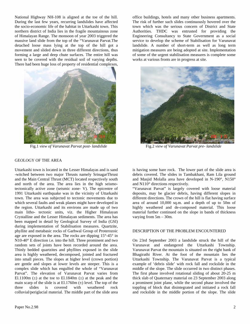
INTRODUCTION The State of Uttarakhand in North India has been witnessing a number of natural disasters such as earthquakes, landslides and flash floods etc. These disasters have greatly affected Uttarkashi Town and surrounding regions of ‘Middle Himalayas’ in the recent past. A number of commercial and residential buildings got buried during the process of massive fall of debris from the mountain. Fortunately, there was no human casualty as the movement of the mountain was very closely being watched and monitored. The Varunavat landslide has been classified as a classical example of debris slide (Debris slide in the crown portion, and rock fall and rockslide in the middle part). Both natural and human-induced factors are responsible for this disastrous slide; however, the main triggering factor has been identified as the surface and groundwater. State Govt. took immediate initiative to invite the attention of Central Govt. and sought requisite resources for tackling the disaster and save the Uttarkashi Town. Central Govt. by immediately appointing a high level Task Force to oversee the treatment works and also by designating the Tehri
Hydro Development Corporation Ltd as the technical consultant for providing the complete engineering solutions to the work, stressed the need to save the ancient and heritage Uttarkashi Town. The stability problem is unique because at the foothills of the mountain runs the National highway which leads to a great Hindu pilgrimage “Gangotri” and Uttarkashi Town, a densely populated town is located. Uttarkashi a town in the State of Uttarakhand in India is located at 78°26’ E and 30°44’ N. It is situated at an elevation of 1150m above sea-level (MSL) on the bank of river Bhagirathi. This picturesque town is also the District Headquarter of Uttarkashi district covering an area of 12.02 sq km and the town has a total population of 16220 (2001 Census). River Bhagirathi is passing almost through the centre of Uttarkashi town. The right bank of the river in Uttarkashi town has a 800-900 m high hill called “Varunavat Parvat” and the city is habitated at the toe of this hill spreading in a land strip around 700-800m width between the river and the hill.
Paper No.2.98 1
National Highway NH-108 is aligned at the toe of the hill. During the last few years, recurring landslides have affected the socio-economic life of the habitat in Uttarkashi town. This northern district of India lies in the fragile mountainous zone of Himalayan Range. The monsoon of year 2003 triggered the massive land slide from the top of the “Varunavat Parvat.The detached loose mass lying at the top of the hill got a movement and slided down in three different directions, thus forming a large and deep chute surfaces. The entire hill was seen to be covered with the residual soil of varying depths. There had been huge loss of property of residential complexes,
office buildings, hotels and many other business apartments. The risk of further such slides continuously hovered over the town which was the serious concern of District and State Authorities. THDC was entrusted for providing the Engineering Consultancy to State Government as a social service to develop the scheme of Stabilisation for Varunavat landslide. A number of short-term as well as long term mitigation measures are being adopted at site. Implementation of some of the urgent stabilisation measures is complete some works at various fronts are in progress at site.
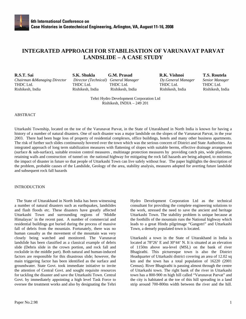
Fig.1 view of Varunavat Parvat post- landslide Fig.2 view of Varunavat Parvat pre- landslide GEOLOGY OF THE AREA Uttarkashi town is located in the Lesser Himalayas and is sand -witched between two major Thrusts namely SrinagarThrust and the Main Central Thrust (MCT) located respectively south and north of the area. The area lies in the high seismo-tectonically active zone (seismic zone- V). The epicentre of 1991 Uttarkashi earthquake was in the vicinity of Uttarkashi town. The area was subjected to tectonic movements due to which several faults and weak planes might have developed in the region. Uttarkashi and its environs are made up of two main litho- tectonic units, viz. the Higher Himalayan Crystalline and the Lesser Himalayan sediments. The area has been mapped in detail by Geological Survey of India (GSI) during implementation of Stabilisation measures. Quartzite, phyllite and metabasic rocks of Garhwal Group of Proterozoic age are exposed in the area. The rocks are dipping 15°-45° in N10-40° E direction i.e. into the hill. Three prominent and two random sets of joints have been recorded around the area. Thinly bedded quartzites and phyllites exposed in the slide area is highly weathered, decomposed, jointed and fractured into small pieces. The slopes at higher level (crown portion) are gentle and slopes at lower levels are steeper. This is a complex slide which has engulfed the whole of “Varunavat Parvat”. The elevation of Varunavat Parvat varies from El.1100m (±) at the toe to El.1840m (±) at the peak and the main scarp of the slide is at El.1760m (±) level. The top of the three slides is covered with weathered rock
is having some bare rock. The lower part of the slide area is debris covered. The slides in Tambakhani, Ram Lila ground and Masjid Molalla area have developed in N-190°, N150° and N110° directions respectively. “Varunavat Parvat” is largely cov
colluvial/periglacial material. The middle part of the slide area
ered with loose material
ESCRIPTION OF THE PROBLEM ENCOUNTERED
n 23rd September 2003 a landslide struck the hill of the
and rockslide in the middle portion of the slope. The slide
deposits, may be glacier debris, having different slopes in different directions. The crown of the hill is flat having surface area of around 10,000 sq.m. and a depth of up to 50m of highly weathered and de-composed material. This loose material further continued on the slope in bands of thickness varying from 5m – 30m. D OVarunavat and endangered the Uttarkashi Township. Varunavat Parvat the mountain is situated on the right bank of Bhagirathi River. At the foot of the mountain lies the Uttarkashi Township. The Varunavat Parvat is a typical example of ‘debris slide’ with rock fall and rockslide in the middle of the slope. The slide occurred in two distinct phases. The first phase involved rotational sliding of about 20-25 m thick slab of Quaternary material on 23 September 2003 along a prominent joint plane, while the second phase involved the toppling of block that disintegrated and initiated a rock fall
Paper No.2.98 2
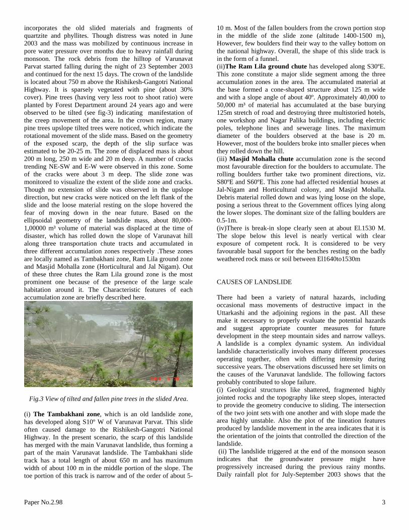
incorporates the old slided materials and fragments of quartzite and phyllites. Though distress was noted in June 2003 and the mass was mobilized by continuous increase in pore water pressure over months due to heavy rainfall during monsoon. The rock debris from the hilltop of Varunavat Parvat started falling during the night of 23 September 2003 and continued for the next 15 days. The crown of the landslide is located about 750 m above the Rishikesh-Gangotri National Highway. It is sparsely vegetated with pine (about 30% cover). Pine trees (having very less root to shoot ratio) were planted by Forest Department around 24 years ago and were observed to be tilted (see fig-3) indicating manifestation of the creep movement of the area. In the crown region, many pine trees upslope tilted trees were noticed, which indicate the rotational movement of the slide mass. Based on the geometry of the exposed scarp, the depth of the slip surface was estimated to be 20-25 m. The zone of displaced mass is about 200 m long, 250 m wide and 20 m deep. A number of cracks trending NE-SW and E-W were observed in this zone. Some of the cracks were about 3 m deep. The slide zone was monitored to visualize the extent of the slide zone and cracks. Though no extension of slide was observed in the upslope direction, but new cracks were noticed on the left flank of the slide and the loose material resting on the slope hovered the fear of moving down in the near future. Based on the ellipsoidal geometry of the landslide mass, about 80,000-1,00000 m³ volume of material was displaced at the time of disaster, which has rolled down the slope of Varunavat hill along three transportation chute tracts and accumulated in three different accumulation zones respectively .These zones are locally named as Tambakhani zone, Ram Lila ground zone and Masjid Mohalla zone (Horticultural and Jal Nigam). Out of these three chutes the Ram Lila ground zone is the most prominent one because of the presence of the large scale habitation around it. The Characteristic features of each accumulation zone are briefly described here.
Fig.3 View of tilted and fallen pine trees in the slided Area. (i) The Tambakhani zone, which is an old landslide zone,
as developed along S10º W of Varunavat Parvat. This slide
ajor slide segment among the three
for the boulders to accumulate. The
e below this level is nearly vertical with clear
AUSES OF LANDSLIDE
of natural hazards, including ccasional mass movements of destructive impact in the
steep slopes, interacted
that the groundwater pressure might have
hoften caused damage to the Rishikesh-Gangotri National Highway. In the present scenario, the scarp of this landslide has merged with the main Varunavat landslide, thus forming a part of the main Varunavat landslide. The Tambakhani slide track has a total length of about 650 m and has maximum width of about 100 m in the middle portion of the slope. The toe portion of this track is narrow and of the order of about 5-
10 m. Most of the fallen boulders from the crown portion stop in the middle of the slide zone (altitude 1400-1500 m), However, few boulders find their way to the valley bottom on the national highway. Overall, the shape of this slide track is in the form of a funnel. (ii)The Ram Lila ground chute has developed along S30ºE. This zone constitute a maccumulation zones in the area. The accumulated material at the base formed a cone-shaped structure about 125 m wide and with a slope angle of about 40º. Approximately 40,000 to 50,000 m³ of material has accumulated at the base burying 125m stretch of road and destroying three multistoried hotels, one workshop and Nagar Palika buildings, including electric poles, telephone lines and sewerage lines. The maximum diameter of the boulders observed at the base is 20 m. However, most of the boulders broke into smaller pieces when they rolled down the hill. (iii) Masjid Mohalla chute accumulation zone is the second most favourable direction rolling boulders further take two prominent directions, viz. S80ºE and S60ºE. This zone had affected residential houses at Jal-Nigam and Horticultural colony, and Masjid Mohalla. Debris material rolled down and was lying loose on the slope, posing a serious threat to the Government offices lying along the lower slopes. The dominant size of the falling boulders are 0.5-1m. (iv)There is break-in slope clearly seen at about El.1530 M. The slopexposure of competent rock. It is considered to be very favourable basal support for the benches resting on the badly weathered rock mass or soil between El1640to1530m C There had been a varietyoUttarkashi and the adjoining regions in the past. All these make it necessary to properly evaluate the potential hazards and suggest appropriate counter measures for future development in the steep mountain sides and narrow valleys. A landslide is a complex dynamic system. An individual landslide characteristically involves many different processes operating together, often with differing intensity during successive years. The observations discussed here set limits on the causes of the Varunavat landslide. The following factors probably contributed to slope failure. (i) Geological structures like shattered, fragmented highly jointed rocks and the topography liketo provide the geometry conducive to sliding. The intersection of the two joint sets with one another and with slope made the area highly unstable. Also the plot of the lineation features produced by landslide movement in the area indicates that it is the orientation of the joints that controlled the direction of the landslide. (ii) The landslide triggered at the end of the monsoon season indicates progressively increased during the previous rainy months. Daily rainfall plot for July-September 2003 shows that the
Paper No.2.98 3

rainfall for the year 2003 is above normal than the average annual rainfall for the previous 14 years .The slide started on the day that the rainfall ceased, i.e. 23rd September 2003. The occurrence of landslide at the end of the rainy season infers that the groundwater was probably near its highest seasonal level. It was the collective rainfall of many months that caused the pore water pressure to rise. (iii) An unlined canal extended across the crown of the slide was constructed by the State forest department.
ings near the base of the slope
6.6 on Richter scale being in the vicinity of
OPE STABILITY ANALYSIS
mit equilibrium analysis the determination or estimation of the shear strength
able 1. Shear Strength properties of Different rock types
ck type Density Cohesion Friction Dilation
Unsubstantiated reports suggest that the water may have percolated for several months before the slide, which could have significantly raised the groundwater level in the hill side and thus reduced the shear resistance. Infiltration from this canal, along with the abundant rainfall, probably also led to further failure of the hill mass. Also in the present case, the infiltration of water form the unlined canal located at about El. 1700 M (approximately 100 m above the landslide scarp) played a major role in the increase of pore water pressure. It is the combination of clay and water that has caused the slope to fail on the Varunavat Parvat. (iv) Steep cut slopes for making roads, pathways and residential & commercial buildmay have further destabilized the slope by removing the basal support. (v) The epicentre of Uttarkashi earthquake (year 1991) of Magnitude Uttarkashi town might be one of the reasons to destabilise the vulnerable slopes in the area. SL One of the most critical steps in any liisparameters (c, Ø) for the surface along which it is anticipated that sliding will take place. In the case of this slope on Varunavat no information about Geotechnical investigations of pre-disaster stage were available. Hence, Initially the approach based on Back Analysis” (i.e. the hill slope in the original condition was stable in limiting equilibrium with factor of safety as 1 and fails when saturated) was applied for determination of shear strength parameters for upper soil of the sliding mass and obtained the values of C= .05 MPa and Ø= 280 . Stability analysis of the slide mass was performed by National Institute of Rock Mechanics, Bangalore by the methods of limit equilibrium and numerical analysis. The slope stability Analysis described herein is for the slope above El.1640 M being the proximity in which the present slide occurred. The analysis was made in a 2-D formulation of the problem applicable to typical landslide sections. The stability analysis was carried out for the different conditions, which revealed that draining out the seepage water in this area is very essential; otherwise unstable conditions will prevail particularly during monsoon period. The analysis made it possible to assess the effect of different factors on the slope
stability. Possible development of hydrostatic pressure during the monsoons affect the slope stability adversely though to a lesser extent as compared to seismic impact. The analysis has shown a positive effect of the flattening the slope faces and reducing the height of the cut slopes The initial analysis was carried out on the existing and on the proposed designed profiles as envisaged with the overburden taken as 20 M. Core drilling was done at locations identified at three different elevations (up to 50 M from the crown) along the slope for ascertaining the soil / rock profile. The benches will be in weathered rock only based on core logs information & the geological sections prepared by GSI were planned. The properties of the weathered and bed rock used in the analysis were estimated on the basis of laboratory testing as shown in table-1. T Ro
Kg/m3 MPa Deg. Deg. Weathered Rock
2300 0.2 30 0.0
Hard 2700 1.0 35 5 Rock
he factors of safety along the different profiles were
wo dimensional models along three different profiles were
he results of analysis in terms of factor of safety of the
Testimated using two dimensional stress analysis to assess the local stability. Two dimensional finite difference technique using FLAC software is used for stress analysis. The factor of safety was estimated using shear strength reduction technique. Tused. The profile along D25 with benches having a height of 15m and profile along section D50 with benches having a height of 10m was selected to assess the stability for bench widths of 4m & 5.5m. The model was simulated with two layers (weathered rock and bed rock) beyond 50m from the crown, the thickness first layer (weathered rock) was exactly not known and hence the analysis was carried out with 10m and 20m thick weathered rock. Toverall slope along the proposed profiles for different cases showed the failure envelope and factor of safety value for the slope with bench width of 4m / 5.5 m with 10m thick weathered rock layer( beyond 50m from the crown). The simulation was also carried out with 5m long rock bolts of 32mm diameter at 3m spacing. The factor of safety did not change significantly as the failure envelope passed below the rock bolts .The factor of safety reduced by about 20 percent when the thickness of the weathered rock beyond 50m from the crown was increased to 20m. The results of analysis shown in figure.4 revealed that factor of safety is always more than 2.
Paper No.2.98 4

Fig.4- Results of 2D Analysis showing shear strain & Factor of safety The overall stability of the slide area with proposed bench geometry was also assessed using three dimensional discontinuum model by incorporating the discontinuities. In the first stage, the stress analysis was carried out and the displacement vectors along different profiles were observed to assess the stability. In second stage, the shear strength reduction was used to estimate the factor of safety. The “strength reduction technique” is typically applied in factor-of-safety calculations by progressively reducing the shear strength of the material to bring the slope to a state of limiting equilibrium. The
failure is identified by the software, by identifying the abrupt rise of the velocity vectors of the blocks along a failure surface. The failure surface, along which the shear strain rates are maximum, is identified by the software automatically. The shear strength reduction techniques applied to three dimensional stress analyses, yielded a factor of safety of 1.65. The velocity vectors along the profile D50 are shown in figure- 5. It can be seen that the large velocity are observed at EL. 1720 and at EL.1740, indicating unstable mechanism, if the shear strength is reduced by 1.65.
Fig.5- Results of 3D Analysis showing velocity vectors & Factor of safety
Paper No.2.98 5
1535
1670
15501560157015801590
1600161016201630164016501660
168016901700171017201730174017501760177017801790
PLATFORM
WAY TO RAMLEELA
GROUND
EXISTING BUILDING
TEHRI
PROTECTION WALL
CATCH PITDYKEPLATFORM
PLATFORM(10-15M WIDE)
TUNNEL
TAMBAKHANI CHUTE
RAMLEELA CHUTE
MASJIDMOHALLA
CHUTE
TOE PROTECTION STRUCTURES
PETROL PUMP
BENCHES
SLIDE EXTREMITY
RETAININGSTRUCTURE
RIVER
BH
AG
IRA
THI
RAMLEELA GROUND
UDYAANOFFICE UDYAAN
COLONY
MASJID COLONY
INTERMEDIATESTRUCTURES
P.G
.CO
LLEG
E
NATIONAL HIGHWAY
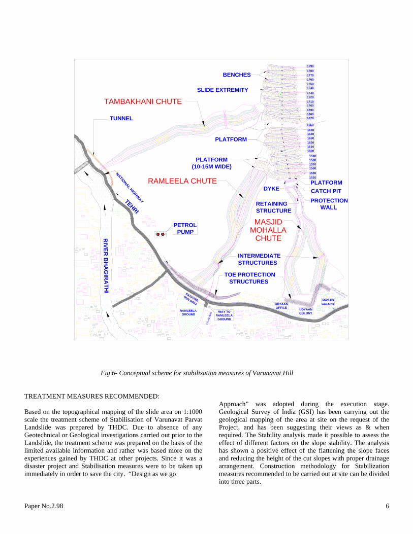
Fig 6- Conceptual scheme for stabilisation measures of Varunavat Hill TREATMENT MEASURES RECOMMENDED:
Based on the topographical mapping of the slide area on 1:1000 scale the treatment scheme of Stabilisation of Varunavat Parvat Landslide was prepared by THDC. Due to absence of any Geotechnical or Geological investigations carried out prior to the Landslide, the treatment scheme was prepared on the basis of the limited available information and rather was based more on the experiences gained by THDC at other projects. Since it was a disaster project and Stabilisation measures were to be taken up immediately in order to save the city. “Design as we go
Approach” was adopted during the execution stage. Geological Survey of India (GSI) has been carrying out the geological mapping of the area at site on the request of the Project, and has been suggesting their views as & when required. The Stability analysis made it possible to assess the effect of different factors on the slope stability. The analysis has shown a positive effect of the flattening the slope faces and reducing the height of the cut slopes with proper drainage arrangement. Construction methodology for Stabilization measures recommended to be carried out at site can be divided into three parts.
Paper No.2.98 6
Crown Treatment: The stabilisation has been carried out by un-loading the loose mass at the crown in suitable slopes and berms and reducing the height of the slopes as well as by reducing the angle of the slope face in accordance with the designed cut slopes based on the findings of the stability analysis as well as keeping the construction at site into considerations. The excavation of slopes was carried out from top (El.1780 M) to downwards (El.1660), and the slopes were stabilized with required berms by providing requisite stabilisation measures. An approach road was made up to the wide platform at an El.1660 M to provide an access to facilitate the construction activities of the project .This platform about 30 m wide with steel barricading has served the function of a catch pit by arresting the falling stone/boulders to save the public residing in the town at the toe of the hill. The following measures were adopted for the long term stability of the Crown treatment.
(i) Reducing the height of the slope. (ii) Reducing the angle of the slope face (iii) Reinforcing the slope. (iv) Providing drainage of the slope (Surface as well as Subsurface)
The slopes of about 10 m to 25 m height with 5.5m berm width were excavated. All the berms were connected fig-6 The excavated muck was then disposed off to the identified dump yards. The slopes and berms so created by modification of the profile were covered with shotcreting/geo-grid/geo-jute to protect against the erosion and weathering actions. Shotcreting was used for the berms and slopes on the weathered rock. The gentle slopes and berms on soil were protected by soil reinforcement with Geo-grid whereas the flatter soil slopes were covered with bio-degradable geo-textiles which can support the growth of the vegetation. The toe of the soil slopes were also stabilized with Gabions wall. The slopes were reinforced with rock bolts to reduce the possibility of local failure of the slopes if any. Pre-stressed cable anchors are being installed on the toe of the steeper rock slopes of greater height or at any other locations where there is wedge formation due to intersection of joints as advised by the geologists of GSI.
Careful disposal of the surface water based on the topography to ensure the surface water away from the slide area is being
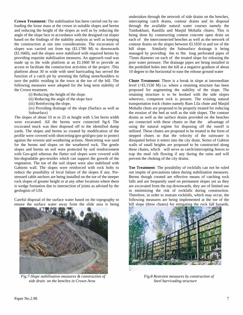
undertaken through the network of side drains on the benches, intercepting catch drains, contour drains and its disposal through the available natural water courses namely the Tambakhani, Ramlila and Masjid Mohalla chutes. This is being done by constructing cement concrete open drain on each of the interconnected benches as well as the network of contour drains on the slopes between El.1650 m and toe of the hill slope. Similarly the Subsurface drainage is being managed by providing 6m to 9m long perforated pipes of 75mm diameter on each of the treated slope for releasing the pore water pressure. The drainage pipes are being installed in the predrilled holes into the hill at a negative gradient of about 10 degree to the horizontal to ease the release ground water Chute Treatment: There is a break in slope at intermediate level (+El.1530 M) i.e. where a retaining structure has been proposed for augmenting the stability of the slope. The retaining structure is to be hooked with the side slopes wherever, competent rock is present. The existing natural transportation track chutes namely Ram Lila chute and Masjid Mohalla chute are proposed to be properly treated for reducing the erosion of the bed as well as the side slopes. The contour drains as well as the surface drains provided on the benches are connected with these chutes so that the advantage of using the natural regime for disposing off the runoff is utilized. These chutes are proposed to be treated in the form of stepped chutes so that the velocity of the rainwater is dissipated before it enters into the city drain. Series of Gabion walls of small heights are proposed to be constructed along these chutes, which will serve as catch/intercepting fences to trap the mud /silt flowing if any during the rains and will prevent the choking of the city drains. Toe Treatment: The possibility of rockfalls can not be ruled out inspite of precautions taken during stabilisation measures. Berms though created are effective means of catching rock falls and are frequently used on permanent slopes yet as they are excavated from the top downwards, they are of limited use in minimizing the risk of rockfalls during construction. Therefore, in order to restrain rockfalls, which may occur, the following measures are being implemented at the toe of the hill slope (three chutes) for mitigating the rock fall hazards.
Fig.7-Slope stabilisation measures & construction of Fig.8 Restraint measures by construction of side drain on the benches in Crown Area Steel barricading structure
Paper No.2.98 7

( i) Retaining Wall of Cement Concrete Blocks placed in two tiers was constructed at the toe of the chute on Ram Lila ground before taking up the treatment work for creating the catch pit to arrest falling of any debris/stone during the construction Stage keeping the safety of the public into consideration. This wall served the purpose satisfactorily during the Crown treatment. However during the treatment of the Ram Lila chute, Cement Concrete Retaining Wall of about 6 Metre height is planned to be constructed. The alternative of Geogrid Wall inititialy envisaged was changed to Cement Concrete wall due the large space requirement for the Geogrid Wall. Probably the most effective permanent rock fall protective system for most highways or in the vicinity of township is the construction of a catch ditch at the toe of the slope. The base of this ditch should be covered by a layer of gravel to absorb the energy of falling rocks and a sturdy barrier fence should be placed between the ditch and the roadway. The location of the Retaining wall /barrier fence can be estimated by means of rockfall analysis by calculating the trajectories based on the available literature. The criterion for the minimum distance between the toe of the slope and the rock fence should be such that no rocks can be allowed to strike the fence before their kinetic energy has been diminished by the first impact on the gravel layer in the rock trap. (ii) Geogrid Wall of about 6 metre height has been constructed to create the catch pit for arresting any debris/boulders for the safety of the public residing in the vicinity. The option of preferring the Geogrid wall (with Gabions facings) to other option was due to its flexibility and high energy absorbing capabilities and having techno -economically a viable alternative at this location (iii) A tunnel of about 350 metre length (see fig. 6) is being constructed on the national highway at Tambakhani to avert the Rock fall hazards (The alternative of Tunnel alternative was preferred to Rock- shed structure due to space constraint on techno-economical considerations. Although, rock sheds structures are widely used on steep slopes above narrow railways or roadways. An effective shelter requires a steeply sloping roof covering a relatively narrow span but in our case because of of a wide multi-lane national highway, it was not possible to design a rock shed structure with sufficient strength to withstand large rockfalls even by considering placing a fill of gravel or soil on top of the rock shed in order to act as both a retarder and a deflector for rockfalls directly into the river. (iv) Evolution of the effective drainage system in the city. The capacity of the existing city drainage system is increased and is planned to be disposed off into the river Bhagirathi.
CONCLUSIONS (i) The stability problem being over the densely populated town is unique so the integrated approach of Stabilization measures with flattening of slopes by removing the overburden mass from the Crown area in suitable berms, effective drainage arrangement (surface & sub-surface), suitable erosion control measures for improving the stability of the slopes along with the multistage protection measures by providing catch pits, wide platforms, retaining walls and construction of tunnel on the national highway for mitigating the rock fall hazards is found to be appropriate. (ii) The various remedial measures which may improve the stability of the Himalayan slopes are proper drainage control, modification of the slope profile and restraint on the unplanned civil constructions due to increasing developmental activities in the region. (iii) With this case study, further research needs to link landslide activity to rainfall-intensity duration trends so that stochastic relationships may be developed to assess high-risk areas in the Himalayan region. REFERENCES Hoek E. and Bray, J.W.1974. Rock Slope Engineering. Report of Geological Survey of India prepared on the Varunavat Parvat
Paper No.2.98 8