Embed Size (px)
Citation preview
IA0501
Integrated Actuator Systems

ALL IN ONE SOLUTION
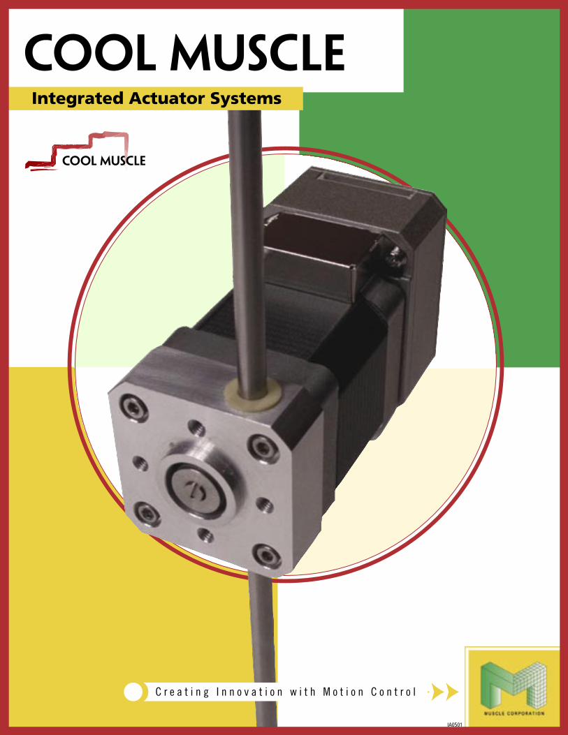
I n teg ra t ing D r i v e r, C o n t r o l l e r , Encoder, and Motor, the Cool Muscle
is an all in one solution for your mo-
tion control.
Integrated Controller
Based around a 32-bit RISC CPU, the integrated controller offers a wide range of hardware and software features. Mo-tion programs can be stored with the motor, eliminating the need for driver and controller boxes. Net worked motors can also communicate with each other.
THE POWER OF COOL MUSCLE
Conventional SystemA typical conventional slider system requires a driver, con-troller, origin switch, limit switches and so on, making the whole system messy and bulky.
Cool Muscle SystemThe Cool Muscle eliminates the need for an external driver box, controller, and switches, making your system compact, and simple.
Very hard to differentiate your product. Leave your competition behind with the Cool Muscle.
Concept1
Integrated Vector Drive Servo SystemThe Cool Muscle is a closed loop vector drive servo system. An intelligent driver with a 32-bit
RISC CPU, a magnetic encoder, and power management are built onto the motor. The Cool
Muscle excels in performance, size, and cost, offering new ways to design and develop with
motion control.
Integrated Driver
A 24VDC sinusoidal driver with regenerative braking imple-ments the Cool Muscle's Vector Driven motions at speeds up to 3000RPM. The closed loop architecture allows the driver to work extremely effectively, resulting in a cool long life servo system.
High Resolution Magnetic Encoder
Minimizing position error and reducing motion ripple can only be achieved with an advanced encoder. The Cool Mus-cle standard magnetic encoder feeds back position changes as small as 0.0072� or 0.43 arch minutes.

2
Cool Muscle TypesThe Cool Muscle supports three different interfaces; Computer, Analog and Pulse. Choose a type that will best suite your need.
Replacing your current pulse driven system with the P type Cool Muscle will save space and remove problems associated with an open loop stepper. P type Cool Muscle supports both CW/CCW and Pulse/Direction.
A typical Slider system with P type Cool Muscle
C type Cool Muscle is the most versatile and feature packed solution among the two types. C type Cool Muscle can be pre-programmed, dynamically controlled by PC or embedded computer and can be networked for multi-axis applications. Digital signals can also activate stored motion programs, creating a compact, powerful machine with simple controls. C type Cool Muscle can also vary speeds or positions in proportion to voltage input level. Set the max speeds or travel distance with ease by parameters. The V type Cool Muscle is an ideal solution for constant feed systems, and valves.
Solution 1 � Preprogram
If your application only requires repetitive motion, you can preprogram the motor, eliminating the need for a controller. Preloaded programs can be executed by a switch, PC or PLC.
A slider system with a pre-programmed C type Cool Muscle.
Type
A slider system with C type Cool Muscle con-trolled by a joy stick
Solution 2 Dynamic CommandIf your application requires complicated motion or arbitrary motion, you can send command dy-namically to the Cool Muscle via PC or embed-ded computers.
A slider system with C type Cool Muscle
Solution 3 NetworkC type Cool Muscles can be daisy chained, pro-viding you with a simple and low cost network solution. There are different ways to network C type Cool Muscles to suit your needs.
A X-Y system with C type Cool Muscles in a daisy chain network.
Solution 4 Analog Control
3
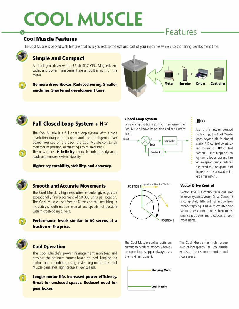
Cool Muscle FeaturesThe Cool Muscle is packed with features that help you reduce the size and cost of your machines while also shortening development time.
Simple and CompactAn intelligent driver with a 32 bit RISC CPU, Magnetic en-coder, and power management are all built in right on the motor.
No more driver/boxes. Reduced wiring. Smaller machines. Shortened development time
Full Closed Loop System + H∞The Cool Muscle is a full closed loop system. With a high resolution magnetic encoder and the intelligent driver board mounted on the back, the Cool Muscle constantly monitors its position, eliminating any missed steps. The new robust H infinity controller tolerates dynamic loads and ensures system stability
Higher repeatability, stability, and accuracy.
Smooth and Accurate MovementsThe Cool Muscle's high resolution encoder gives you an exceptionally fine placement of 50,000 units per rotation. The Cool Muscle uses Vector Drive control, resulting in incredibly smooth motion even at low speeds not possible with microstepping drivers.
Performance levels similar to AC servos at a fraction of the price.
Cool OperationThe Cool Muscle's power management monitors and provides the optimum current based on load, keeping the motor cool. In addition, using a stepping motor, the Cool Muscle generates high torque at low speeds.
Longer motor life. Increased power efficiency. Great for enclosed spaces. Reduced need for gear boxes.
Motor Encoder Driver Controller
+ + +
Closed Loop SystemBy receiving position input from the sensor the Cool Muscle knows its position and can correct itself.
InputController
Feedback
Error
+-
H∞Using the newest control technology, the Cool Muscle goes beyond old fashioned static PID control by utiliz-ing the robust H∞ control system. H∞ responds to dynamic loads across the entire speed range, reduces the need to tune gains, and increases the allowable in-ertia mismatch .
POSITION 1
POSITION 2
Speed and Direction Vector Vector Drive Control
Vector Drive is a control technique used in servo systems. Vector Drive Control is a completely different technique from micro-stepping. Unlike micro-stepping Vector Drive Control is not subject to res-onance problems and produces smooth movements.
The Cool Muscle applies optimum current to produce motion whereas an open loop stepper always uses the maximum current.
The Cool Muscle has high torque even at low speeds. The Cool Muscle excels at both smooth motion and slow speeds.
Cool Muscle
Stepping Motor
Features

PCEmbedded ComputerPLCSwitch
Analog Input
PulsesCW/CCWStep/Direction
PositionSpeed
Pre-ProgrammedDynamic Command
FeaturesVarious InterfacesThe Cool Muscle can be controlled by various methods, in-cluding Pulse, Analog, Computer and PLC. Choose the type that best suits your needs.
Minimum modification required to your system. A wide range of solutions for your system.
ProgrammableProgram the Cool Muscle to create the motion you need. Define motion profiles and create programs using easy-to-understand Cool Muscle Language (CML). Motion pro-grams you create can be downloaded to the Cool Muscle. The programs can be executed via PC, embedded computer or simply using I/Os.
Great solution for repetitive motion. Simple and compact machines.
User Definable ParametersDefine the character of your Cool Muscle to suit your needs. The Cool Muscle gives you over 35 parameters. Parameters can easily be set using CML.
Flexibly change your motor characteristics.�
�Unique Home Search MethodA home search parameter lets you select a home search method. Eliminate the need for home switches using our unique home search technique. Home can be determined using a hard-stop/bumper instead of using a home switch. The Cool Muscle hits a bumper at very low speed and keeps pushing until it reaches a specified current level, at which the motor determines that it has reached home. This method eliminates the need for home switch and wiring.
Software limit
You can set software limits using Cool Muscle parameters. Set limits on both CW and CCW sides to eliminate limit switches.
These two software features just saved you the cost of three sensors and the time needed to install wiring and calibrate them.
USEFUL PARAMETER EXAMPLES
CMLCool Muscle Language is a set of ASCII commands that lets you easily create motion programs. Programs you create can be downloaded to the Cool Muscle via free software from Muscle Corporation, Cool Works Lite or any standard terminal program.
P1=1000P2=2000S1=200S2=300A1=50A2=150T1=20
B1A1,S1,P1S2,P2,P1C2B2A2,S1,P3
K46=1
K48=10000
K58=200000
K52=50
K53=250
K54=2...
4
Control Variations
Define motion profiles such as speed, accel-eration, position and timer.
Define motion programs us-ing the motion profiles defined above.
Origin search set to automatic origin search using bumper.
Origin offset distance set to 10000 pulses.
Software limit + side set to 200000 pulses.
position P gain set to 50.
Velocity P gain set to 250.
I gain set to 2.

Programmable I/OsConfigure and assign multiple functions to I/Os on the Cool Muscle. Cool Muscle has 4 inputs and 2 outputs that can be used as digital, analog, serial or pulse counter (Input only). The new Cool Muscle lets you assign a function to each point of a signal.
Custom I/O. Flexible application of powerfully built in features.
Input Functions examples:Origin sensorManual feedManual JogExecute Bank1,2,3Origin SearchMotor FreeEnable MotorExecute Next StepExecute Previous Step
Output Functions examples:AlarmIn-positionAnalog Output for monitoring
Virtual Input SignalMake the most of the I/O ports by taking advantage of Cool Muscle's unique virtual signal technique. The Cool Muscle creates two signals based on a single input signal by set-ting a time delay between the two signals, allowing you to assign multiple functions to a single input.
Eliminates the need for external I/O board.
Advanced MotionChange speeds or accelerations while the motor is in op-eration. The Cool Muscle supports advanced motions such as continuous PTP and PTP motion with different accelera-tions and decelerations, Push mode and more. The powerful push mode is also standard allowing for elec-tric simulation of common pneumatic operations.
�Quick and Slow response signals example: You can assign Alarm Reset, Motor Free and Enable Motor to the rising edge of Quick response, target voltage level and falling edge of Slow response signals respectively. Input functions are set by parameters.
�����������
����������
�����
�����
�����
�����
���
���
���
��
������ ��������
������������������ ����������������
Push Mode: Push mode mimics a typical pneumatic cylinder motion. It keeps push-ing for a given time and at a set current level when a motor encounters a resistance such as bumper and stopper.
5
Input
Quick Response Signal
Slow Response Signal
Rising Edge
Alarm Reset
Target Voltage Level
Falling Edge
Rising Edge
Target Voltage Level
Disable Motor Falling Edge
Enable Motor
Continuous PTP: There is no stops in motion between origin and P3. Speed and acceleration are changed at each point.
Speed
Time
Speed
Time
Features
NetworkThe Cool Muscle provides you with different networking solutions that best suit your needs. Connect multiple Cool Muscles in a daisy chain style network. In the daisy chain network Cool Muscles can tell other motors to activate pro-grams as well as receive commands from a computer or an embedded controller.
Simple network solution that lowers your cost.
PC��PLC
Master motor
��Slave motor��
��Slave motor��

���������������������
������������
����������
����������������
��������������������
��������������������
PRODUCT NAME FORMAT
Technical Specifications�
RL-45T RL-60TBall Screw Lead (mm) 12 6 12 6Max Speed (mm/sec) 600 300 600 300Rated Force (N) 40 80 67 133Max Force (N) 117 238 201 402Load Capability ( H) 5 10 8 16Loda Capability(V) 1.5 3 2.5 5Ball Screw Lead (mm) 12 6 12 6Ball Screw Diameter (mm) 8 12Repetitive Accuracy(mm) +/-0.020Backlash(mm) 0.1Moment (Nm) Ma=Mb=12 Mc=31 Ma=Mb=25.7 Mc=58Life(km) 5000
Moments Product Cutaway
RL-45T-06-150-17L30-CRodless Actuator
Ball Screw Lead Stroke
50�100...N
06 6mm lead�12 12mm lead
Motor Type
17S3017L3023S3023L20
C ComputerP Pulse
Interface
6Specifications
Body Size
45 45mm (H)60 60mm (H)
Mb
Ma
Mc
Integrated Actuators

Unit (mm)
Stroke Effective Stroke
Mechanical Stroke
L1 L2 n N Weight(Kg)
0050 50 60 206 151 1 2 1.300100 100 110 256 201 2 3 1.410150 150 160 306 251 2 3 1.520200 200 210 356 301 3 4 1.620250 250 260 406 351 3 4 1.730300 300 310 456 401 4 5 1.840350 250 360 506 451 4 5 1.950400 400 410 556 501 5 6 2.070450 450 460 606 551 5 6 2.170500 500 510 656 601 6 7 2.28
All RL actuators include the same function set and wiring specifications as the Cool Muscle integrated servo system allowing for accurate and reliable positioning in both PLC control environments and PC control systems. The RL45T accepts both the CM1-C-17S30 and CM1-C-17L30 Cool Muscle motors. Please refer to the Cool Muscle Integrated Servo System catalog for motor sped if cations.
The RL actuators use a wide THK SRS LM guide for stability and linear precision. Quiet motion is achieved through the use of the single piece Reli-a-Flex shaft coupling and the ball retainer of the SRS LM guide. Additionally, the RL actuator’s ball screw has a special coating called QZ that lengthens the maintenance cycle and life time of the actuator.
83.5
53
19
36
30
45
36.5
42
57.2
4-Ø 4.5 through holeM4 dep 7.5
2xN-M4 Dep8
81
9
38
19100n x 100
26
20
32
L1
L229
14
24
45
25
RL-45T INTELLIGENT ACTUATOR
7
8Specifications
646049
6442
393123110
22
35
L183.5
53
42
100n x 100 33
52
215060
L235
25
2 x N-M5 Dep 9
4-M5 Dep 104-Ø 5.5 through hole
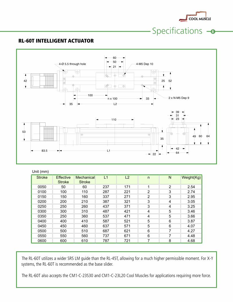
Unit (mm)
Stroke Effective Stroke
Mechanical Stroke
L1 L2 n N Weight(Kg)
0050 50 60 237 171 1 2 2.540100 100 110 287 221 2 3 2.740150 150 160 337 271 2 3 2.950200 200 210 387 321 3 4 3.050250 250 260 437 371 3 4 3.250300 300 310 487 421 4 5 3.460350 250 360 537 471 4 5 3.660400 400 410 587 521 5 6 3.870450 450 460 637 571 5 6 4.070500 500 510 687 621 6 7 4.270550 550 560 737 671 6 7 4.480600 600 610 787 721 7 8 4.68
The RL-60T utilizes a wider SRS LM guide than the RL-45T, allowing for a much higher permissible moment. For X-Y systems, the RL-60T is recommended as the base slider.
The RL-60T also accepts the CM1-C-23S30 and CM1-C-23L20 Cool Muscles for applications requiring more force.
RL-60T INTELLIGENT ACTUATOR
SpecificationsPRODUCT NAME FORMAT
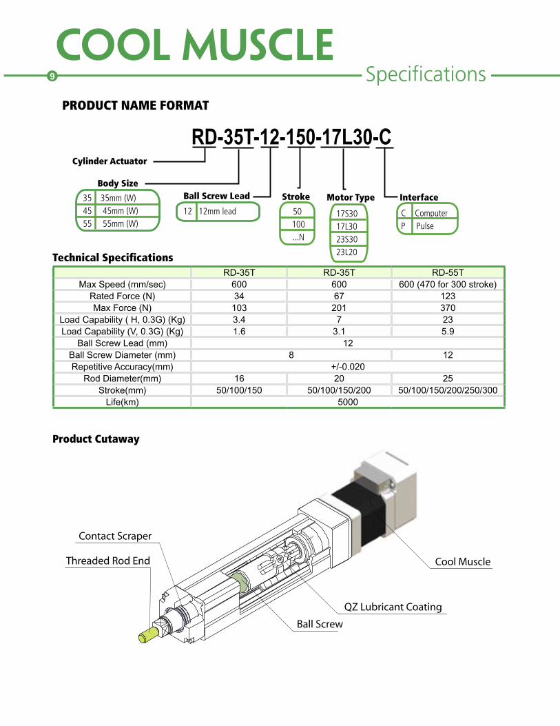
Technical SpecificationsRD-35T RD-35T RD-55T
Max Speed (mm/sec) 600 600 600 (470 for 300 stroke)Rated Force (N) 34 67 123Max Force (N) 103 201 370
Load Capability ( H, 0.3G) (Kg) 3.4 7 23Load Capability (V, 0.3G) (Kg) 1.6 3.1 5.9
Ball Screw Lead (mm) 12Ball Screw Diameter (mm) 8 12Repetitive Accuracy(mm) +/-0.020
Rod Diameter(mm) 16 20 25Stroke(mm) 50/100/150 50/100/150/200 50/100/150/200/250/300
Life(km) 5000
Product Cutaway
RD-35T-12-150-17L30-CCylinder Actuator
Ball Screw Lead Stroke
50�100...N
12 12mm lead
Motor Type
17S3017L3023S3023L20
C ComputerP Pulse
Interface
Body Size
35 35mm (W)45 45mm (W)55 55mm (W)
���������������
����������������
����������
�����������
��������������������
9

10Specifications
Unit (mm)
Stroke Effective Stroke
L L1 H J K Weight(Kg)(w/17S30)
0050 50 240 161 2 100 6 1.20100 100 290 211 3 150 8 1.40150 150 340 261 4 200 10 1.5
An excellent replacement for pneumatic cylinders, the RD series actuator offers fast, precise motion without any of the noise associated with air driven systems. Overall system complexity and maintenance is greatly reduced resulting is a cost effective solution for your next application.
All RD actuators include the same function set and wiring specifcations as the Cool Muscle integrated servo system allowiing for accurate and reliable postioning in both PLC control envirnoments and PC control systems. The RD-35T accepts both the 17S30 and 17L30 Cool Muscle motors. Please refer to the Cool Muscle Integrated Servo System catalog for motor spedifcations.
As with the RT series, the RD actuator’s ball screw is coated with QZ lubricant. This reduces maintenance and lengthens the overall life of the cylinder.
RD-35T INTELLIGENT ACTUATOR
5342
H x 50 = J
50
41
25
L116.583.73
K-M3 Dep 4
Greasable position >73 35
11
1121
38.5
0.5
4-M3 Dep 10
PCD29
37.5 Stroke = S
18
7.5
2
10
Grease Pit
M8 x 1.25
Specifications
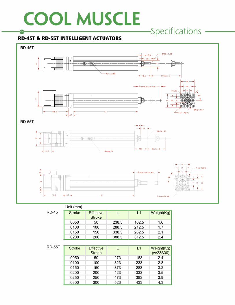
Unit (mm)
Stroke Effective Stroke
L L1 Weight(Kg)
0050 50 238.5 162.5 1.60100 100 288.5 212.5 1.70150 150 338.5 262.5 2.10200 200 388.5 312.5 2.4
RD-45T & RD-55T INTELLIGENT ACTUATORS
Stroke Effective Stroke
L L1 Weight(Kg)(w/23S30)
0050 50 273 183 2.40100 100 323 233 2.80150 150 373 283 3.20200 200 423 333 3.50250 250 473 383 3.90300 300 523 433 4.3
17
30
55
17 30 55
L116.578.5
53
10.7
7
Grease position >83
249
M12 x 1.25
Stroke = SGrease Pit
45.5
T Shape for M4
45°
4-M5 Dep 12
56 42
29.5
4253
83.73 L116.5
Greasable position >75
142545
14
25
45
45°
T Shape for M34-M4 Dep 10
PCD53
42.5 Stroke = S
22
8.5
Ø 20
M10 x 1.25
Grease Pit
RD-45T
RD-55T
RD-45T
RD-55T
11

12SpecificationsPRODUCT NAME FORMAT
Technical Specifications (units: mm)
ModelBall
ScrewLead
Outer Rail
LengthStroke
Max. Velocity (mm/s)
Force(N)
Repeatability(Running Parallelism)
Backlash(P Grade)
Starting Torque
PA15(w/11L30)
1
75100125150 175200
315681
106131156
50 489
+-0.004(0.020)
0.010 0.4
2
75100125150 175200
315681
106131156
100 244
PA20(w/11L30)
1100150200
4191
14150 489
S Grade = +-0.010P Grade = +-0.003
0.020(0.003)
0.5
PA26(w/17L30)
2
150200250300
69119169219
100 1600S Grade =+-0.010
P Grade = +-0.003
0.020(0.003)
1.5
PA33
6
150200300400500600
61111211311411511
(w/17L30)300
(w/23L20)200
533
1308 S Grade = +-0.010
P Grade = +-0.003
0.020(0.003)
7
10
150200300400500600
61111211311411511
(w/17L30)500
(w/23L20)333
320
785
PA15-02-150-S-17L30-CPA Actuator
Ball Screw Lead Stroke
50100...N
12 12mm lead
Motor Type
17S3017L3023S3023L20
C ComputerP Pulse
InterfaceBody Size
15 15mm H20 20mm H26 26mm H33 33mm H
Grade
SP

Specifications
TOTAL L
2-M2 DEP 3
G
L1 (RAIL LENGTH)L2
16.6
Lm
2.3
5
16.644
Ø2grease nipple
9.5
±1
19
12
30
15
14
4.5
2*2-M2 DEP 3
37.5
23.225.56.5 12
7.5 5
(G)
2 n-Ø3.4 through hole
(n-1)~50
50
10
Ø6 counter bore DEP 2
332314
4-M3 DEP 4
38.6
Connector(Molex) 53254-1210
75
14.8
L2(RAIL LENGTH)
2*n-\U+FF933.4through hole
(n-1)~60
L1Lm
12
495±1
2512
G
60
Connector(Molex)53254-1210
(10)
G
13
20
40
18
185
23
37.5
17.1
TOTAL L
8.5
\U+FF936.5counter bore depth3
4633.2
204-M3depth4.5 6
148
2*2-M2.6depth4
Unit (mm)
Rail Length L1
Stroke L2Motor Lm
w/11S30 w/11L30L
w/11S30 w/11L30G n
75 31 129
66 80
200 214 12.5 2100 56 154 225 239 25 2125 81 179 250 264 12.5 3150 106 204 275 289 25 3175 131 229 300 314 12.5 4200 156 254 325 339 25 4
PA20 Series
Unit (mm)
Rail Length L2
Stroke L1Motor Lm
w/11S30 w/11L30L
w/11S30 w/11L30G n
100 41 15966 80
230 244 20 2150 91 209 280 294 15 3200 141 259 330 344 40 3
PA15 Series
13
14
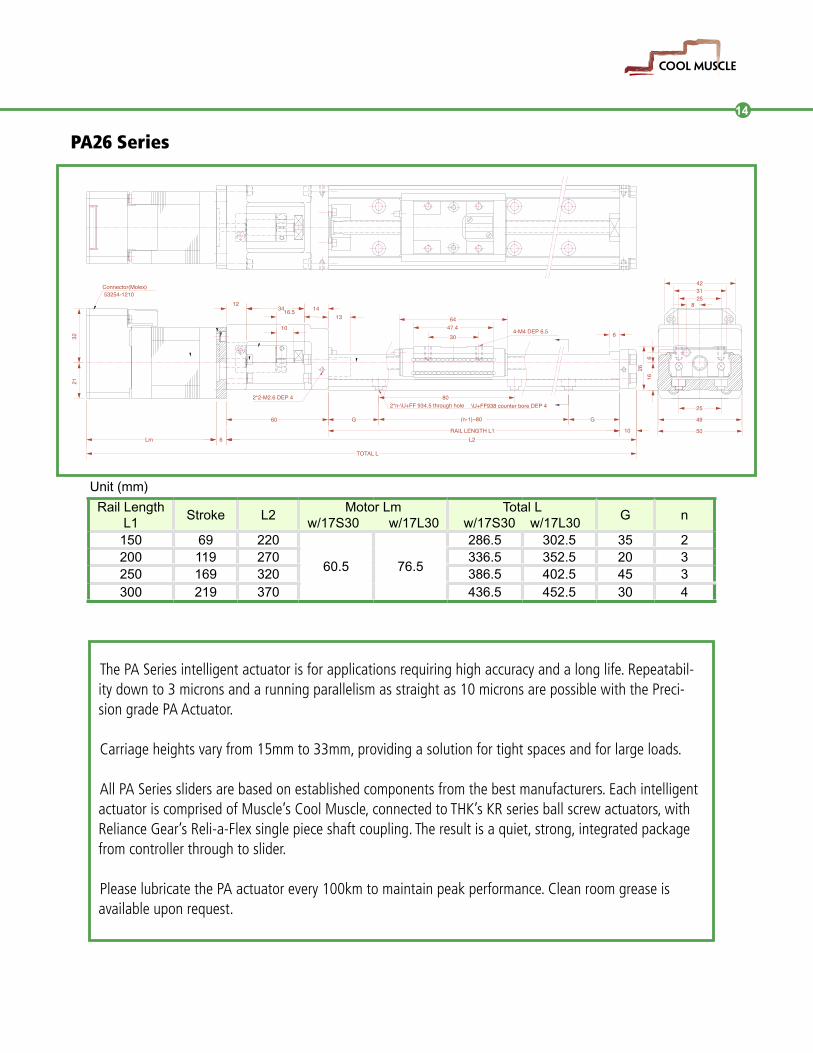
PA26 Series
Unit (mm)
Rail Length L1
Stroke L2Motor Lm
w/17S30 w/17L30Total L
w/17S30 w/17L30G n
150 69 220
60.5 76.5
286.5 302.5 35 2200 119 270 336.5 352.5 20 3250 169 320 386.5 402.5 45 3300 219 370 436.5 452.5 30 4
The PA Series intelligent actuator is for applications requiring high accuracy and a long life. Repeatabil-ity down to 3 microns and a running parallelism as straight as 10 microns are possible with the Preci-sion grade PA Actuator.
Carriage heights vary from 15mm to 33mm, providing a solution for tight spaces and for large loads.
All PA Series sliders are based on established components from the best manufacturers. Each intelligent actuator is comprised of Muscle’s Cool Muscle, connected to THK’s KR series ball screw actuators, with Reliance Gear’s Reli-a-Flex single piece shaft coupling. The result is a quiet, strong, integrated package from controller through to slider.
Please lubricate the PA actuator every 100km to maintain peak performance. Clean room grease is available upon request.
423125
616
25
49
5010
GG (n-1)~80
RAIL LENGTH L1
80
L2
TOTAL L
60
2*2-M2.6 DEP 4
Lm 6
\U+FF938 counter bore DEP 42*n-\U+FF 934.5 through hole
3416.512
1064
1413
26
6
8
304-M4 DEP 6.547.4
Connector(Molex) 53254-1210
2132

PA33 Series
Unit (mm)
Rail Length L1
Stroke L2Motor Lm
w/17S30 w/17L30Total L
w/17S30 w/17L30G H F N n
150 61 220
60.5 76.5
286.5 302.5 25 25 100 2 2200 111 270 336.5 352.5 50 50 100 2 2300 211 370 436.5 452.5 50 50 200 2 3400 311 470 536.5 552.5 50 100 200 2 4500 411 570 636.5 652.5 50 50 200 3 5600 511 670 736.5 752.5 50 100 200 3 6
Lm 6
59 G 100 11
11
G
5.5
RAIL LENGTH L1L2
TOTAL L
183110169
2132
33
236.5
60
30
3037.4
42
2*n-Ø5.5 through holeØ9.5 counter bore DEP 5.4
2*N-M2.6 DEP 4
7654
304-M5 DEP 8 A
A
VIEW ON ARROW "A - A"
53254-1210Connector(Molex)
H FH
All PA Series sliders use Reliance Gear Company Lt.d Reli-a-Flex™ couplings. These couplings are matched tomotor torque limits and shaft sizes. The positional accuracy and axial flexibility of theReli-a-Flex™ ensures that each PA slider operates to its maximum potential.
More information on the Reli-a-Flex™ coupling can be found at the end of this catalog or on our web site at:www.coolmuscle.com
15
16
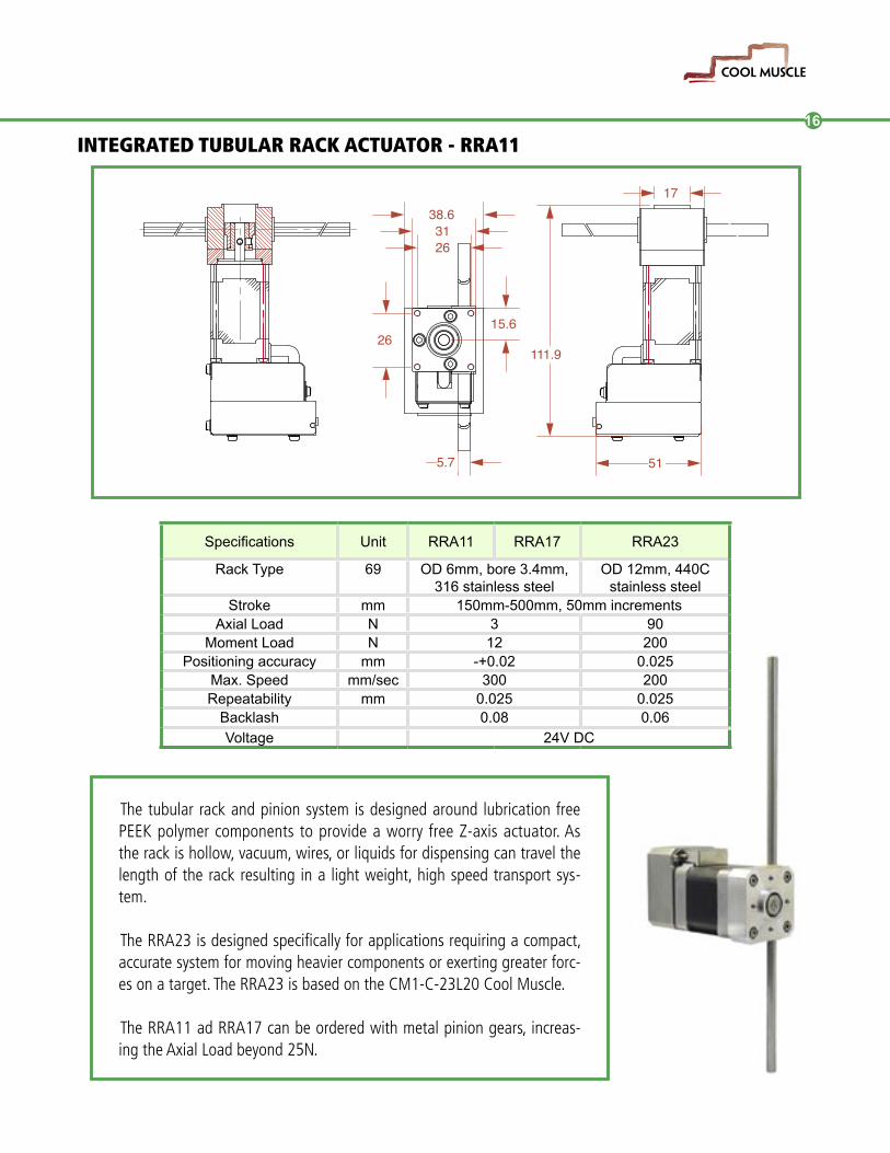
INTEGRATED TUBULAR RACK ACTUATOR - RRA11
Specifications Unit RRA11 RRA17 RRA23
Rack Type 69 OD 6mm, bore 3.4mm, 316 stainless steel
OD 12mm, 440C stainless steel
Stroke mm 150mm-500mm, 50mm incrementsAxial Load N 3 90
Moment Load N 12 200Positioning accuracy mm -+0.02 0.025
Max. Speed mm/sec 300 200Repeatability mm 0.025 0.025
Backlash 0.08 0.06Voltage 24V DC
111.9
31
51
1738.631
15.6
5.7
26
26
The tubular rack and pinion system is designed around lubrication free PEEK polymer components to provide a worry free Z-axis actuator. As the rack is hollow, vacuum, wires, or liquids for dispensing can travel the length of the rack resulting in a light weight, high speed transport sys-tem.
The RRA23 is designed specifically for applications requiring a compact, accurate system for moving heavier components or exerting greater forc-es on a target. The RRA23 is based on the CM1-C-23L20 Cool Muscle.
The RRA11 ad RRA17 can be ordered with metal pinion gears, increas-ing the Axial Load beyond 25N.

�����������������������������
������������������������������������������
�������������������
�����������
INTEGRATED TUBULAR RACK ACTUATOR - RRA17
Removing the size and weight associated with linear guides and ballscrews, the Rack ac-tuator provides a light weight solution for dispensing or trans-porting. Multi-axis systems will respond more quickly and require less force to move and stop accurately.
Utilizing the Cool Muscle’s inte-grated intelligence will also sim-plify wiring and control design. A single input can trigger a series of moves, or a serial connection allows for dynamic control.
When requesting information, please specify any modifications required to the rack to allow for fittings.
44
44
9.5
4 HOLESM4x8 DEEPEQUISPACED ON 31 PCD
TUBULAR RACKOD: 6BORE: 3.4LENGTH: 250
8.5
20.00019.975Ø
Ø5
8
2
17
18
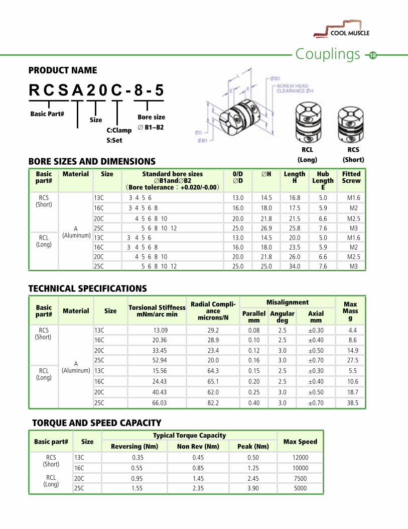
PRODUCT NAME
RCSA 2 0 C - 8 - 5
BORE SIZES AND DIMENSIONSBasic part#
Material Size Standard bore sizes∅B1and∅B2
(Bore tolerance:+0.020/-0.00)
0/D∅D
∅H LengthH
HubLength
E
FittedScrew
RCS(Short)
A�(Aluminum)
13C 3 4 5 6 13.0 14.5 16.8 5.0 M1.6
16C 3 4 5 6 8 16.0 18.0 17.5 5.9 M2
20C 4 5 6 8 10 20.0 21.8 21.5 6.6 M2.525C 5 6 8 10 12 25.0 26.9 25.8 7.6 M3
RCL(Long)
13C 3 4 5 6 13.0 14.5 20.0 5.0 M1.616C 3 4 5 6 8 16.0 18.0 23.5 5.9 M220C 4 5 6 8 10 20.0 21.8 26.0 6.6 M2.525C 5 6 8 10 12 25.0 25.0 34.0 7.6 M3
TECHNICAL SPECIFICATIONS
Basic part# Material Size Torsional Stiffness
mNm/arc minRadial Compli-
ancemicrons/N
Misalignment Max Mass
gParallelmm
Angulardeg
Axialmm
RCS(Short)�
A(Aluminum)
13C 13.09 29.2 0.08 2.5 ±0.30 4.416C 20.36 28.9 0.10 2.5 ±0.40 8.6
20C 33.45 23.4 0.12 3.0 ±0.50 14.925C 52.94 20.0 0.16 3.0 ±0.70 27.5
RCL(Long)
13C 15.56 64.3 0.15 2.5 ±0.30 5.5
16C 24.43 65.1 0.20 2.5 ±0.40 10.6
20C 40.43 62.0 0.25 3.0 ±0.50 18.7
25C 66.03 82.2 0.40 3.0 ±0.70 38.5
TORQUE AND SPEED CAPACITY
Basic part# SizeTypical Torque Capacity
Max SpeedReversing (Nm) Non Rev (Nm) Peak (Nm)
RCS(Short)
RCL(Long)
13C 0.35 0.45 0.50 12000
16C 0.55 0.85 1.25 10000
20C 0.95 1.45 2.45 750025C 1.55 2.35 3.90 5000
RCL RCS (Long) (Short)
Basic Part#Size
C:ClampS:Set
Bore size
∅�B1−B2
Couplings

��������
�Myostat Motion Control
17817 Leslie Street, Unit 43
Newmarket Ontario Canada L3Y 8C6
Tel: 905-836-4441 Fax: 905-836-1214
www.coolmuscle.com
www.coolmuscle.com