Embed Size (px)
Citation preview

EXPERIMENTAL SEISMIC TESTING OF PRECAST U-GIRDERS INTEGRALLY CONNECTED TO CAST-IN-PLACE BENT CAPS
Kevin L. Almer1
David H. Sanders2
Abstract The purpose of this study is to develop and examine integral connection details of precast superstructures with cast-in-place bent caps subjected to longitudinal seismic loading. Analytical modeling and experimental testing of four, 40 percent precast U-girder specimens will be used to develop a design methodology. The specimens investigate the effects of post-tensioning on connection behavior. Specimens with post-tensioning and spliced reinforcement provide adequate girder connection details, and the influence of post-tensioning seems to reduce the dependency on external joint stirrups to transfer the seismic forces. The paper describes experimental results from two of the tests. Introduction Bridge structures are an integral part of the nation’s highway infrastructure. As the infrastructure continues to age, existing bridges may need to be widened, retrofitted, or replaced; and new bridges may need to be built. Often, any one of the infrastructure improvements mentioned above will occur in heavily congested areas where traffic delays and public safety are of major concerns. In high seismic regions, a common bridge type is a continuous, cast-in-place concrete superstructure integrally connected with a cast-in-place substructure in order to transfer high seismic moments and shear forces. This monolithic bridge construction provides good continuity for transfer of seismic forces; however, falsework over the traffic lanes is needed while the superstructure is cast. This falsework is potentially dangerous both to motorists and construction workers due to the reduction in bridge clearance when added. Using precast concrete girders for the superstructure eliminates the need for falsework over traffic lanes and also allows for accelerating the construction time needed to place the superstructure, thereby reducing the traffic delay to the public and reducing the danger to the construction workers and motorists. This construction process has great advantages when widening and retrofitting existing bridges as well as new bridge construction in highly congested areas. The lack of experimental data on the behavior of precast girder integral connections subjected to seismic forces has led designers and agencies to either over-design these types of connections or not use them at all (Holombo et al. 2000). The purpose of this study is to investigate the longitudinal seismic behavior of the integral connection between precast concrete girders and cast-in-place concrete and develop design guidelines based on analytical and experimental testing for the Nevada Department of Transportation (NDOT). 1 Grad. Assist., Dept. of Civil and Envir. Engineering, University of Nevada, Reno 2 Professor, Dept. of Civil and Envir. Engineering, University of Nevada, Reno

Previous Research The only prior experimental research pertaining to the precast girder integral connection in the longitudinal direction was conducted at the University of California at San Diego La Jolla, California in the late 1990’s (Holombo et al. 2000). This study investigated the continuity of a post-tensioned spliced precast girder system subjected to longitudinal seismic forces. Two 40% scaled bridge models featuring bulb-tee girders and bathtub girders that represented typical bridge construction in California were tested. In both tests, the superstructure was designed remain elastic while the plastic hinges developed in the column. Negative moment continuity was provided by post-tensioning of the girders over the bent cap and positive moment continuity was provided through splicing the extended bars and strands at the bottom of the girder. The results of the test indicated good ductility performance of the integral connection with only minor strength degradation. The superstructure was able to remain essentially elastic with only minor cracks occurring that closed after the removal of seismic loading. Another important conclusion the researches reported was the proportion of the column seismic moment to be resisted over the width of the superstructure. They concluded that the column moment should be proportioned according to the relative stiffness of the integral system, or roughly two-thirds of column moment to be resisted by the two adjacent girders and the other one-third to be resisted by the remaining girders. Another important detail they recommended was to extend the column longitudinal reinforcement as far as possible into the bent cap for better transfer of the seismic forces. Girder Connection Parameters A prototype U-Girder, representative of NDOT U-Girders, is shown in Figure 1. Strength and ductility characteristics of the prototype section were determined using the cross-sectional software program XTRACT (XTRACT 2002). The prototype girder contains post-tensioning, prestressing, and mild-reinforcement and is spliced to a cast-in-place bent cap. Negative moment continuity is provided by the post-tensioning and the mild reinforcement in the deck, while the positive moment continuity is provided through the mild reinforcement in the girder soffit. The post-tensioning is very advantageous because it allows the section to have a high negative moment capacity without having to increase reinforcement amounts in the deck. However, in continuous systems, post-tensioning introduces secondary positive moments in the joint region requiring more positive reinforcement. High secondary moments are not desired because there is less space to place reinforcement in positive moment regions. These secondary moments can be minimized and controlled by the designer through proper tendon configurations. Not only is post-tensioning advantageous for negative moment capacity, it also increases positive moment capacity, so if second order moments are small, reinforcement requirements can be further reduced in the girder soffit. From the prototype girder in Figure 1, the positive moment details consist of extending only the mild reinforcement into the joint and either lap-splicing or mechanically splicing the bars. Using the un-tensioned strands for the required
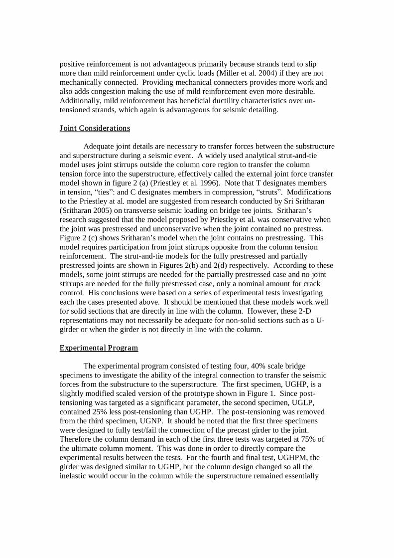
positive reinforcement is not advantageous primarily because strands tend to slip more than mild reinforcement under cyclic loads (Miller et al. 2004) if they are not mechanically connected. Providing mechanical connecters provides more work and also adds congestion making the use of mild reinforcement even more desirable. Additionally, mild reinforcement has beneficial ductility characteristics over un-tensioned strands, which again is advantageous for seismic detailing. Joint Considerations Adequate joint details are necessary to transfer forces between the substructure and superstructure during a seismic event. A widely used analytical strut-and-tie model uses joint stirrups outside the column core region to transfer the column tension force into the superstructure, effectively called the external joint force transfer model shown in figure 2 (a) (Priestley et al. 1996). Note that T designates members in tension, “ties”: and C designates members in compression, “struts”. Modifications to the Priestley at al. model are suggested from research conducted by Sri Sritharan (Sritharan 2005) on transverse seismic loading on bridge tee joints. Sritharan’s research suggested that the model proposed by Priestley et al. was conservative when the joint was prestressed and unconservative when the joint contained no prestress. Figure 2 (c) shows Sritharan’s model when the joint contains no prestressing. This model requires participation from joint stirrups opposite from the column tension reinforcement. The strut-and-tie models for the fully prestressed and partially prestressed joints are shown in Figures 2(b) and 2(d) respectively. According to these models, some joint stirrups are needed for the partially prestressed case and no joint stirrups are needed for the fully prestressed case, only a nominal amount for crack control. His conclusions were based on a series of experimental tests investigating each the cases presented above. It should be mentioned that these models work well for solid sections that are directly in line with the column. However, these 2-D representations may not necessarily be adequate for non-solid sections such as a U-girder or when the girder is not directly in line with the column. Experimental Program The experimental program consisted of testing four, 40% scale bridge specimens to investigate the ability of the integral connection to transfer the seismic forces from the substructure to the superstructure. The first specimen, UGHP, is a slightly modified scaled version of the prototype shown in Figure 1. Since post-tensioning was targeted as a significant parameter, the second specimen, UGLP, contained 25% less post-tensioning than UGHP. The post-tensioning was removed from the third specimen, UGNP. It should be noted that the first three specimens were designed to fully test/fail the connection of the precast girder to the joint. Therefore the column demand in each of the first three tests was targeted at 75% of the ultimate column moment. This was done in order to directly compare the experimental results between the tests. For the fourth and final test, UGHPM, the girder was designed similar to UGHP, but the column design changed so all the inelastic would occur in the column while the superstructure remained essentially
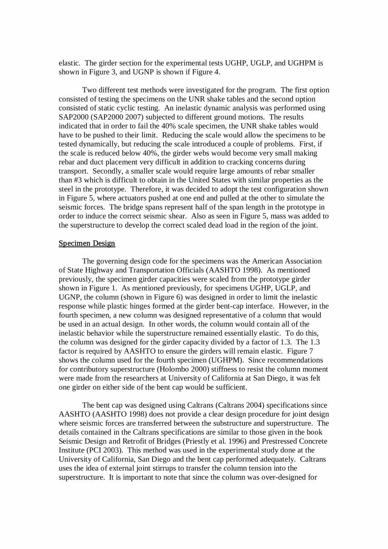
elastic. The girder section for the experimental tests UGHP, UGLP, and UGHPM is shown in Figure 3, and UGNP is shown if Figure 4. Two different test methods were investigated for the program. The first option consisted of testing the specimens on the UNR shake tables and the second option consisted of static cyclic testing. An inelastic dynamic analysis was performed using SAP2000 (SAP2000 2007) subjected to different ground motions. The results indicated that in order to fail the 40% scale specimen, the UNR shake tables would have to be pushed to their limit. Reducing the scale would allow the specimens to be tested dynamically, but reducing the scale introduced a couple of problems. First, if the scale is reduced below 40%, the girder webs would become very small making rebar and duct placement very difficult in addition to cracking concerns during transport. Secondly, a smaller scale would require large amounts of rebar smaller than #3 which is difficult to obtain in the United States with similar properties as the steel in the prototype. Therefore, it was decided to adopt the test configuration shown in Figure 5, where actuators pushed at one end and pulled at the other to simulate the seismic forces. The bridge spans represent half of the span length in the prototype in order to induce the correct seismic shear. Also as seen in Figure 5, mass was added to the superstructure to develop the correct scaled dead load in the region of the joint. Specimen Design The governing design code for the specimens was the American Association of State Highway and Transportation Officials (AASHTO 1998). As mentioned previously, the specimen girder capacities were scaled from the prototype girder shown in Figure 1. As mentioned previously, for specimens UGHP, UGLP, and UGNP, the column (shown in Figure 6) was designed in order to limit the inelastic response while plastic hinges formed at the girder bent-cap interface. However, in the fourth specimen, a new column was designed representative of a column that would be used in an actual design. In other words, the column would contain all of the inelastic behavior while the superstructure remained essentially elastic. To do this, the column was designed for the girder capacity divided by a factor of 1.3. The 1.3 factor is required by AASHTO to ensure the girders will remain elastic. Figure 7 shows the column used for the fourth specimen (UGHPM). Since recommendations for contributory superstructure (Holombo 2000) stiffness to resist the column moment were made from the researchers at University of California at San Diego, it was felt one girder on either side of the bent cap would be sufficient. The bent cap was designed using Caltrans (Caltrans 2004) specifications since AASHTO (AASHTO 1998) does not provide a clear design procedure for joint design where seismic forces are transferred between the substructure and superstructure. The details contained in the Caltrans specifications are similar to those given in the book Seismic Design and Retrofit of Bridges (Priestly et al. 1996) and Prestressed Concrete Institute (PCI 2003). This method was used in the experimental study done at the University of California, San Diego and the bent cap performed adequately. Caltrans uses the idea of external joint stirrups to transfer the column tension into the superstructure. It is important to note that since the column was over-designed for

specimens UGHP, UGLP, and UGNP, the amount of joint stirrups provided was based on the column moment demand required to produce failure in the superstructure, not the nominal capacity of the columns required by Caltrans. External joint stirrups for each specimen are shown in Figure 8. The column-footing connection was designed as a two-way hinge using a methodology developed from research conducted at UNR (Cheng et al. 2006). The study found that shear friction theory either overestimated or underestimated the hinge shear strength. A new method was developed based on observed shear failure mechanisms. Using a base hinge reduced the column seismic shear force required to develop the superstructure moments as compared to a fixed case. Experimental Results At the time this paper was written, specimens UGHP and UGLP have been tested while specimens UGNP and UGHPM are in the process of being constructed. The loading protocol used consisted of reverse cyclic loading consistent with guidelines given in the Recommendations for Seismic Performance Testing of Bridge Piers (FHA 2004). Loading protocols for specimens UGHP and UGLP are given in Figures 9 and 10 respectively. As seen in the Figures 9 and 10, the cycles were run in force control until ¾ of the yield displacement, thereafter, the cycles were run in displacement control until failure. The resulting hysteresis curves for UGHP and UGLP are shown in Figures 11 and 12 respectively. Based on analytical work, it was predicted that plastic hinges would form on both sides of the joint with the negative moment side of the joint reaching its rotation capacity. Figures 13 and 14 compare the predicted response with the measured response for UGHP and UGLP. These figures show very good correlation between the predicted vs. measured response thus indicating that the girder connection details were adequate to develop the designed capacities. When comparing the hysteretic curves and the pushover curves, it is very clear that UGLP had a significant advantage over UGHP from a ductility standpoint as expected. Figure 15 shows the joint region for both tests at specimen failure. An important observation is how the bent-cap, in both tests, remains fairly undamaged beneath the deck. This result suggests that the external joint steel requirements according to Caltrans (Caltrans 2004) are on the over-conservative side. External joint stirrup strain data indicated levels well below yield, again supporting evidence that a reduced number of external stirrups are needed. Strut-and-Tie Representations A main objective of this project is to be able to describe the force transfer in the joint. Since the joint region has a complex stress strain field, strut-and-tie models provide a way to describe the flow of forces between the superstructure and the substructure. The Caltrans specifications for joint design are based on the strut-and-tie model shown in Figure 2(a). Again, this is a two-dimensional solution to a three-dimensional problem in our case. Guidelines that Caltrans uses are ultimately based on the amount of column reinforcement only, regardless the amount of post-

tensioning in the joint. Sritharan’s research suggests a minimal need for joint reinforcement in the transverse direction when prestressing is applied due to the broader compression struts developed in the joint (Sritharan 2005). Post-tensioning in the longitudinal direction also has benefits similar to the transverse direction due to the broad compression struts developed. A three-dimensional strut-and-tie model schematic for specimen UGHP before the external joint stirrups participate in the joint transfer is shown in Figure 16. Forces in this model correspond to load stage 6 of the cyclic load history. The key to this model is the ability of strut BC to anchor then column tension sufficiently. This model is helpful in suggesting a strut-and-tie model for the fourth specimen, UGHPM. The proposed model for specimen UGHPM is shown in Figure 17. The difference between this model and the one shown in Figure 16 is the participation of the external joint stirrup. In this case, the compression strut from the positive moment side cannot anchor the tension alone and needs assistance from the external stirrups to help anchor the column tension. An interesting note is that for this specimen, the external stirrups on the positive moment side where enough to anchor all of the column tension. However, this might not always be the case, the stirrups on the negative moment side may need to participate similar to Figure 2(c). Again it depends on the situation. From these strut-and-tie models, it is also evident that ties are needed in the y direction of the x-y plane to direct the beam compression forces towards the column forces. This “three-dimensional effect” is also recognized in Holombo’s work (Holombo 2000). Summary This paper presents research relating to experimental work on seismic testing of precast U-girders integrally connected to cast-in-place bent caps. Analytical and experimental work on four 40% U-girder specimens will be used to develop guidelines for integral connections. The research primarily investigates the effect of longitudinal post-tensioning on connection behavior. Based on work conducted to date, current joint design methods seem to be conservative for joints with post-tensioning applied. Girder connection details consisting of post-tensioning for negative moment capacity and spliced mild-reinforcement in the positive moment region are effective in developing the full moment capacity of the section adjacent to the bent cap. Experimental tests investigating connection performance without post-tensioning and investigating a design representative of field conditions (i.e. Column inelastic behavior while superstructure elastic) are planned in the beginning of 2008. References AASHTO (1998), LRFD Bridge Design Specification, second edition, American Association of State Highway and Transportation officials, Washington , D.C. Caltrans (2004), Seismic Design Criteria, Version 1.3, California Department of Transportation, Sacramento, CA. Cheng, Z., Saiidi, M., and Sanders, D. (2006), “Development of Seismic Design Method for Reinforced Concrete Two-Way Bridge Column Hinges,” Center for Civil

Engineering Earthquake Research, Department of Civil Engineering, University of Nevada, Reno, Nevada, Report No CCEER-06-01. Federal Highway Administration (FHA) (2004), Recommendations for Seismic Performance Testing of Bridge Piers, Research, Development, & Technology Turner-Fairbank Highway Research Center, McLean, VA. Holombo, J., Priestley, M.J.N., and Seible, F (2000), “Continuity of Precast Prestressed Spliced-Girder Bridges Under Seismic Loads,” PCI Journal, 45(2), 40–63. Miller et al. (2004), NCHRP Report 519: Connection of Simple-Span Precast Concrete for Continuity. Transportation Research Board, National Research Council; Washington, D.C. PCI (2003), Precast Prestressed Concrete Bridge Design Manual, second edition, Precast /Prestressed Concrete Institute, Chicago, IL. Priestley, M.J.N., Seible, F., and Calvi, G.M. (1996), Seismic Design and Retrofit of Bridges, John Wiley and Sons, Inc., New York. Sap2000 (2007), Version Advanced 11, Computers and Structures, Inc., Berkeley, CA. Sritharan, Sri (2005), “Strut-and-Tie Analysis of Bridge Tee Joints Subjected to Seismic Actions,” Journal of Structural Engineering, Vol. 131, No.9. XTRACT (2002), Version 2.6.2, Imbsen Software Systems, Sacramento, CA.

Figure 1: NDOT Prototype U-Girder Cross-Section
Figure 2: Previously Developed STM, (a) Priestley et al. (1996), (b)-(d) Sritharan
(2005)

Figure 3: UGHP, UGLP, UGHPM U-Girder Cross-Section
Figure 4: UGNP U-Girder Cross-Section
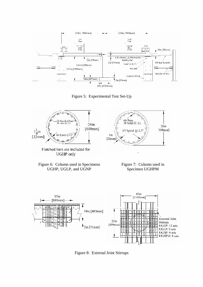
Figure 5: Experimental Test Set-Up
.
Figure 8: External Joint Stirrups
Figure 7: Column used in Specimen UGHPM
Figure 6: Column used in Specimens UGHP, UGLP, and UGNP

-2
-1.5
-1
-0.5
0
0.5
1
1.5
2
0 1 2 3 4 5 6 7 8 9 10 11 12 13 14 15 16 17 18 19 20Load Cycle
Am
plitu
de
Force Control Displacement Control
0.05 Rn
0.45 Rn
0.75 Rn
y
1.25 y
1.75 y
Determination of y
Rn = 85.4 kips Load Cycle Load Estimated Displ.0.05 Rn 4.27 kips 0.04288 in0.15 Rn 12.81 kips 0.1286 in0.30 Rn 25.62 kips 0.2573 in0.45 Rn 38.43 kips 0.5747 in0.60 Rn 51.24 kips 1.09 in0.75 Rn 64.05 kips 1.605 inEstimated y = 2.14 in NOTE : 1 kip = 4.45 kN 1in = 25.4mm
0.6 Rn
0.30 Rn0.15 Rn
1S
1N
2S
2N
3S 4S
3N 4N
5S 6S
5N 6N
7S 8S
7N 8N
9S 10S
9N 10N
11S 12S
11N 12N
13S 14S
13N 14N
15S 16S
15N 16N
17S 18S
17N 18N
19S 20S
19N 20N
2.25 y
Load Stage 1
Load Stage 2
Load Stage 3
Load Stage 4
Load Stage 5
Load Stage 6
Load Stage 7
Load Stage8
Load Stage 9
Load Stage 10
Figure 9: UGHP Reverse Cyclic Lateral Load History
-5
-4
-3
-2
-1
0
1
2
3
4
5
0 1 2 3 4 5 6 7 8 9 10 11 12 13 14 15 16 17 18 19 20 21 22 23 24 25 26 27Load Cycle
Am
plitu
de
Force Control Displacement Control
0.05 Rn
0.45 Rn0.75 Rn
y
1.5 y
2.0 y
Determination of y
Rn = 76.35 kips Load Cycle Load Estimated Displ.0.05 Rn 3.82 kips 0.03836 in0.15 Rn 11.45 kips 0.1150 in0.30 Rn 22.91 kips 0.2301 in0.45 Rn 35.24 kips 0.4110 in0.60 Rn 45.81 kips 0.8716 in0.75 Rn 57.26 kips 1.332 inEstimated y = 1.78 in Note: 1 kip = 4.45 kN 1 in = 25.4 mm
0.6 Rn
0.30 Rn0.15 Rn
1S
1N
2S
2N
3S 4S
3N 4N
5S 6S
5N 6N
7S 8S
7N 8N
9S 10S
9N 10N
11S 12S
11N 12N
13S 14S
13N 14N
15S 16S
15N 16N
17S 18S
17N 18N
19S 20S
19N 20N
2.5 y
Load Stage
1
Load Stage
2
Load Stage
3
Load Stage
4
Load Stage
5
Load Stage
6
Load Stage
7
Load Stage
8
Load Stage
9
LoadStage
10
21S 22S
3.0 y
LoadStage
11
21N 22N
23S 24S
3.5 y
LoadStage
12
23N 24N
25S 26S4.5 y
Load Stage 13
25N 26N
27S4.75 y
Figure 10: UGLP Reverse Cyclic Lateral Load History

-90
-70
-50
-30
-10
10
30
50
70
90
-7 -5 -3 -1 1 3 5 7
Displacement (in)
Forc
e (k
ips)
-400.3
-311.4
-222.4
-133.4
-44.5
44.5
133.4
222.4
311.4
400.3-254 -203 -152 -102 -50.8 0 50.8 101.6 152.4 203.2 254
Displacement (mm)
Forc
e (k
N)
Figure 11: UGHP Hystersis Curve
-80
-60
-40
-20
0
20
40
60
80
-10 -8 -6 -4 -2 0 2 4 6 8 10
Displacement (in)
Forc
e (k
ips)
-355.9
-266.9
-177.9
-89.0
0.0
89.0
177.9
266.9
355.9-254 -203 -152 -102 -50.8 0 50.8 101.6 152.4 203.2 254
Displacement (mm)
Forc
e (k
N)
Figure 12: UGLP Hysteresis Curve
0
10
20
30
40
50
60
70
80
90
0 1 2 3 4 5 6 7Displacement (in)
Forc
e (k
ips)
0.0
44.5
89.0
133.4
177.9
222.4
266.9
311.4
355.9
400.30 25.4 50.8 76.2 101.6 127 152.4 177.8
Displacement (mm)
Forc
e (k
N)
Sap2000UGHP Experimental
0
10
20
30
40
50
60
70
80
90
0 1 2 3 4 5 6 7 8 9 10Displacement (in)
Forc
e (k
ips)
0.0
44.5
89.0
133.4
177.9
222.4
266.9
311.4
355.9
400.30 25.4 50.8 76.2 101.6 127 152.4 177.8 203.2 228.6 254
Displacement (mm)
Forc
e (k
N)
Sap2000
Experimental
Figure 13: UGHP Pushover Curve Analytical vs.
Experimental Comparison
Figure 14: UGLP Pushover Curve Analytical vs.
Experimental Comparison

Figure 15: Joint Region for UGHP and UGLP at Specimen Failure
Figure 16: Suggested Strut-and-Tie Model UGHP before External Joint Participation
UGHP Joint UGLP Joint
Cab 137.1kip Tbbi 113.3kip Tc 133kip
Cbc 177.9kip Tffi 85.3kip Cc 154.5kip
Cce 195.1kip Tggi 80.9kip Vc 30kip
Cde 157.4kip Cbl1 101.5kip
Ccci 100kip Cbl2 49kip
Ceei 179.6kip Vbl 16.3kip
Cef 145.6kip Tbl 7kip
Cgi 51.6kip Cbr 130kip
Ceg 96kip Tbr 16.5kip
Vbr 5.3kip

Figure 17: Suggested Strut-and-Tie Model UGHPM


![INTEGRALLY CLOSED SUBRINGS OF AN INTEGRAL DOMAIN · Hence if R is an integrally closed domain, then R + A[{XA}] is integrally closed if and only if A = \/A. In the remainder of this](https://img.dokumen.tips/doc/110x75/5cfc3e2388c993fe058b83e7/integrally-closed-subrings-of-an-integral-hence-if-r-is-an-integrally-closed.jpg)