Embed Size (px)
Citation preview

SURGICAL TECHNIQUEIntegra® Silicone PIP Implant
Step 1 • Initial Incision & Joint Exposure
Step 2 • Medullary Canal Opening & Alignment
Preoperative Assessment
Incise the central slip tendon longitudinally from the middle of the proximal phalanx and distally past its insertion point into the middle phalanx. Using sharp dissection, elevate the extensor mechanism radially and ulnarly, separating it from the underlying periosteum over the proximal phalanx. Elevate the extensor insertion at the base of the proximal phalanx radially and ulnarly, and flex the middle phalanx. This will create radial and ulnar tendinous bands with each, including 1/2 of the central tendon and a lateral band. At the end of the procedure, the “split tendon” halves are sutured to each other with or without drill hole fixation to the middle phalangeal insertion.
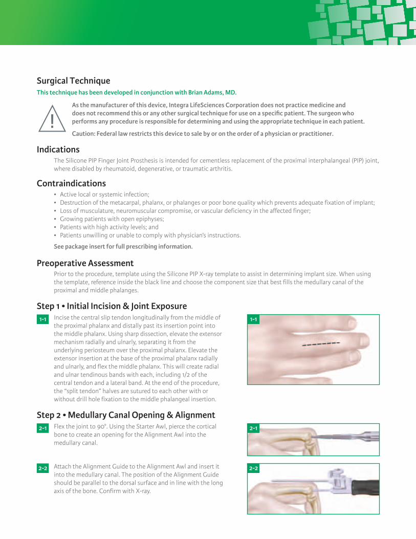
Flex the joint to 90°. Using the Starter Awl, pierce the cortical bone to create an opening for the Alignment Awl into the medullary canal.
Prior to the procedure, template using the Silicone PIP X-ray template to assist in determining implant size. When using the template, reference inside the black line and choose the component size that best fills the medullary canal of the proximal and middle phalanges.
1- 1
2- 1
2- 2
1- 1
2- 1
Attach the Alignment Guide to the Alignment Awl and insert it into the medullary canal. The position of the Alignment Guide should be parallel to the dorsal surface and in line with the long axis of the bone. Confirm with X-ray.
2- 2
Indications
Contraindications
The Silicone PIP Finger Joint Prosthesis is intended for cementless replacement of the proximal interphalangeal (PIP) joint, where disabled by rheumatoid, degenerative, or traumatic arthritis.
• Activelocalorsystemicinfection;• Destructionofthemetacarpal,phalanx,orphalangesorpoorbonequalitywhichpreventsadequatefixationofimplant;• Lossofmusculature,neuromuscularcompromise,orvasculardeficiencyintheaffectedfinger;• Growingpatientswithopenepiphyses;• Patientswithhighactivitylevels;and• Patientsunwillingorunabletocomplywithphysician’sinstructions.
See package insert for full prescribing information.
As the manufacturer of this device, Integra LifeSciences Corporation does not practice medicine and does not recommend this or any other surgical technique for use on a specific patient. The surgeon who performs any procedure is responsible for determining and using the appropriate technique in each patient.
Caution: Federal law restricts this device to sale by or on the order of a physician or practitioner.
Surgical TechniqueThis technique has been developed in conjunction with Brian Adams, MD.

Step 5 • Middle Phalanx Exposure & Distal Surface Preparation
Step 6 • Distal Component Broaching
Step 7 • Trial insertion – Reduction – Removal
Step 8 • Implant Placement
Step 9 • Closure
Postoperative Care
Step 3 • Proximal Osteotomy – Vertical Cut
Step 4 • Proximal Component Broaching
After completion of the proximal side, hyper-flex the joint to expose the articular surface of the middle phalanx. Use a rongeur to remove spurs from the base of the middle phalanx. The articular surface is then contoured (side cutting burr/oscillating saw/osteotome) to provide a surface against which the implant will be flush.
Attach the Alignment Guide to the Size 0 SPIP Distal Broach. Insert the broach into the medullary canal. The broach must beinsertedfullyintothemedullarycanal.Broachsequentiallywithlargersizesuntilcorticalcontactisobtained.Insomecases, middle phalanx bone stock may be hard and sclerotic. If the broach cannot be fully inserted, additional bone stock must be removed. Aside-cuttingburrortwistdrillmayberequired.
Flex the joint and insert the appropriate size SPIP Trial. Using smooth forceps, insert the proximal stem first, followed by the distal stem with the finger in flexion to aid final seating. Extend the joint and check for proper sizing, the trial should fit flush against the middle and proximal phalanges. The finger should extend and flex passively with ease but with minimal lateral play or laxity with traction.
After successful sizing, trial insertion and reduction, open the appropriate Ascension Silicone PIP sterile component. Using smooth forceps insert the proximal stem first, followed by the distal stem with the finger in flexion to aid final seating. Extend the joint and confirm proper sizing, motion, and stability previously obtained with the trials.
Repair the extensor apparatus using a row of 4.0 non-absorbable sutures. Close the skin with non-absorbable sutures. With the finger in resting posture of 30° MP flexion and 10-20° PIP flexion, apply a padded dressing with a plaster splint.
Guarded active flexion and extension exercises can commence several days after the procedure, ensuring that any repaired collateral ligaments are protected from deviating forces for 4-6 weeks. Alternatively, the finger can be splinted in a resting position for up to 4 weeks, after which range of motion exercises can begin.
Maintain Alignment Awl position and replace the Alignment Guide with the Vertical Cut Guide. The osteotomy is placed 0.5-1.0 mm distal to the proximal attachments of the collateral ligaments. Using a sagittal saw, remove the articular surface of the proximal phalanx using the Vertical Cut Guide to start the cut. Remove the awl and complete the vertical cut established with the Vertical Cut Guide.
Attach the Alignment Guide to the Size 0 SPIP Proximal Broach. Insert the broach into the meduallary canal. The broach must beinsertedfullyintomedullarycanal.Broachsequentiallywithlarger sizes until cortical contact is obtained. In some cases, proximal phalanx bone stock may be hard and sclerotic. If broach cannot be fully inserted, additional bone stock must be removed.Aside-cuttingburrortwistdrillmayberequired.
3- 1
4- 1
3- 1
4- 1
8- 1 8- 1

Integra®
Silicone PIP Implant
For more information or to place an order, please contact:Integra n 311 Enterprise Drive, Plainsboro, NJ 08536877-444-1122 USA n 609-936-5400 outside USA n 866-800-7742 fax integralife.com
Integra and the Integra logo are registered trademarks of Integra LifeSciences Corporation. ©2012 Integra LifeSciences Corporation. All rights reserved. Printed in USA. LC-04-527-001 rev D
Catalog Number
Catalog Number
Implants
Instruments
SPIP-520-0 Silicone PIP Implant, Size 0 SPIP-520-1 Silicone PIP Implant, Size 1 SPIP-520-2 Silicone PIP Implant, Size 2 SPIP-520-3 Silicone PIP Implant, Size 3 SPIP-520-4 Silicone PIP Implant, Size 4 SPIP-520-5 Silicone PIP Implant, Size 5
ALG-100-00 Alignment GuideAWL-100-01 Starter AwlAWL-200-00 Alignment AwlBRH-525-0P Proximal Broach, Size 0BRH-525-1P Proximal Broach, Size 1BRH-525-2P Proximal Broach, Size 2BRH-525-3P Proximal Broach, Size 3BRH-525-4P Proximal Broach, Size 4BRH-525-5P Proximal Broach, Size 5BRH-525-0D Distal Broach, Size 0BRH-525-1D Distal Broach, Size 1BRH-525-2D Distal Broach, Size 2BRH-525-3D Distal Broach, Size 3BRH-525-4D Distal Broach, Size 4BRH-525-5D Distal Broach, Size 5OSG-442-00 Vertical Cut Guide TRL-520-0 SPIP Trial, Size 0TRL-520-1 SPIP Trial, Size 1TRL-520-2 SPIP Trial, Size 2TRL-520-3 SPIP Trial, Size 3TRL-520-4 SPIP Trial, Size 4TRL-520-5 SPIP Trial, Size 5
Catalog Number Size (A) Proximal Stem Length (B) Distal Stem Length (C) Hinge Width
Implant Dimensions (mm)
SPIP-520-0 0 11.5 8.5 6.4SPIP-520-1 1 12.7 9.7 7.2SPIP-520-2 2 13.7 11.8 8.2SPIP-520-3 3 15.2 13.1 9.3SPIP-520-4 4 16.8 14.7 10.2SPIP-520-5 5 19.0 16.6 11.2
Description
Description
1. Starter Awl
2. Alignment Guide
3. Alignment Awl
4. Vertical Cut Guide
5. Proximal Broaches
6. Distal Broaches
7. Trials
Instrumentation
13
2
7 65
4