Embed Size (px)
Citation preview
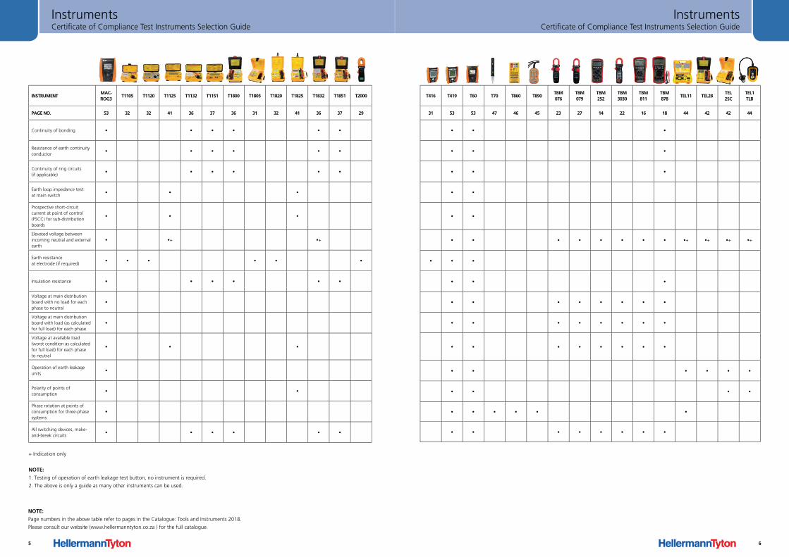
Certificate of Compliance Test Instruments Selection GuideInstruments
+ Indication only
NOTE:
1. Testing of operation of earth leakage test button, no instrument is required.
2. The above is only a guide as many other instruments can be used.
INSTRUMENTMAC-ROG3
T1105 T1120 T1125 T1132 T1151 T1800 T1805 T1820 T1825 T1832 T1851 T2000
PAGE NO. 53 32 32 41 36 37 36 31 32 41 36 37 29
Continuity of bonding • • • • • •
Resistance of earth continuity conductor
• • • • • •
Continuity of ring circuits (if applicable)
• • • • • •
Earth loop impedance test: at main switch
• • •
Prospective short-circuit current at point of control (PSCC) for sub-distribution boards
• • •
Elevated voltage between incoming neutral and external earth
• •+ •+
Earth resistance at electrode (if required)
• • • • • •
Insulation resistance • • • • • •
Voltage at main distribution board with no load for each phase to neutral
•
Voltage at main distribution board with load (as calculated for full load) for each phase
•
Voltage at available load (worst condition as calculated for full load) for each phase to neutral
• • •
Operation of earth leakage units
•
Polarity of points of consumption
• •
Phase rotation at points of consumption for three-phase systems
•
All switching devices, make-and-break circuits
• • • • • •
NOTE:
Page numbers in the above table refer to pages in the Catalogue: Tools and Instruments 2018.
Please consult our website (www.hellermanntyton.co.za ) for the full catalogue.
5
Certificate of Compliance Test Instruments Selection GuideInstruments
InstrumentMAC-ROG3
T1105 T1120 T1125 T1132 T1151 T1800 T1805 T1820 T1825 T1832 T1851 T2000 T416 T419 T60 T70 T860 T890TBM076
TBM079
TBM252
TBM 3030
TBM811
TBM878
TEL11 TEL28TEL 2SC
TEL1 TLB
Page No. 31 53 53 47 46 45 23 27 14 22 16 18 44 42 42 44
Continuity of bonding • • • • • • • •
Resistance of earth continuity conductor • • • • • • • •
Continuity of ring circuits (if applicable) • • • • • • • • •
Earth loop impedance test: at main switch
• • • • •
Prospective short-circuit current at point of control (PSCC) for sub-distribution boards
• • • • •
Elevated voltage between incoming neutral and external earth • • • • • • • • • •+ •+ •+ •+
Earth resistance at electrode (if required)
• • • • • • • •
Insulation resistance • • • • • • • •
Voltage at main distribution board with no load for each phase to neutral
• • • • • • • •
Voltage at main distribution board with load (as calculated for full load) for each phase
• • • • • • • •
Voltage at available load (worst condition as calculated for full load) for each phase to neutral
• • • • • • • • •
Operation of earth leakage units • • • • • • •
Polarity of points of consumptio
• • • • • •
Phase rotation at points of consumption for three-phase systems • • • • • • •
All switching devices, make-and-break circuits • • • • • • • • • •
6
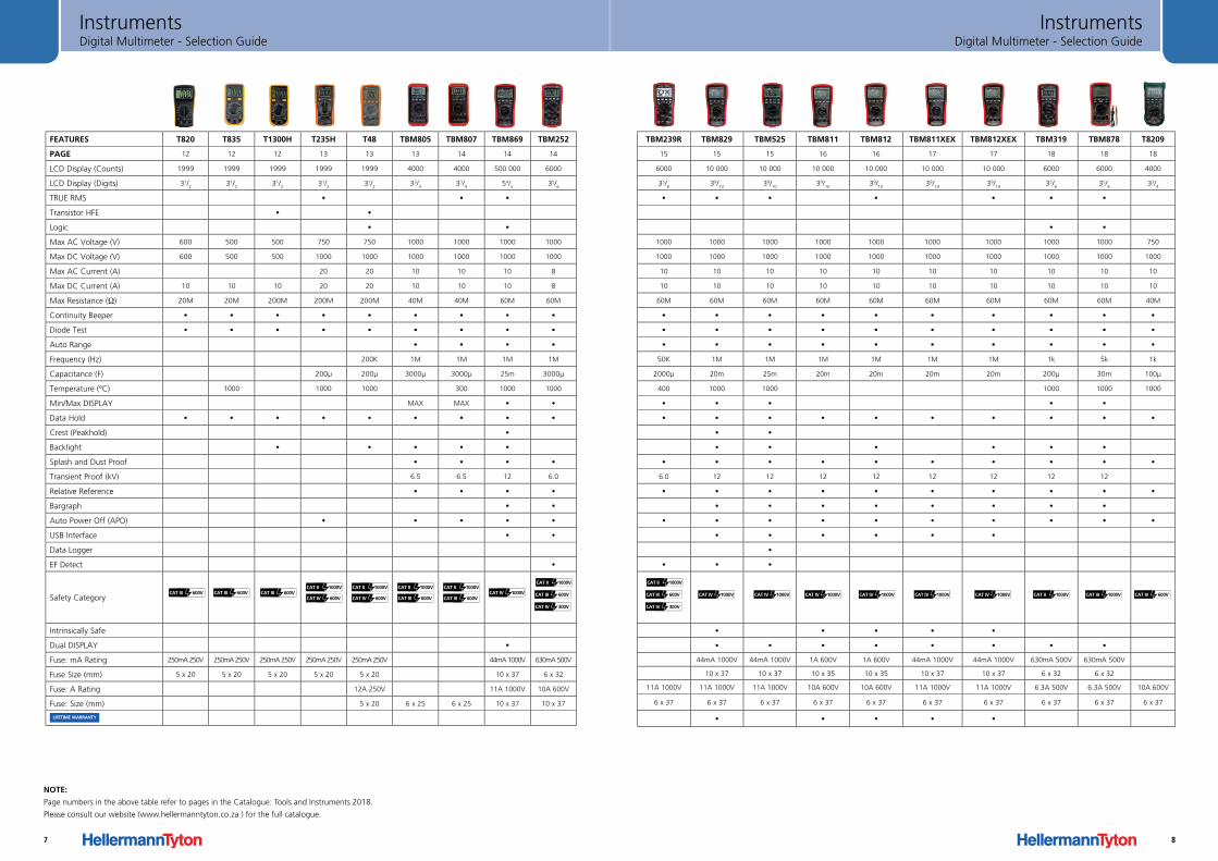
Digital Multimeter - Selection GuideInstruments
TBM239R TBM829 TBM525 TBM811 TBM812 TBM811XEX TBM812XEX TBM319 TBM878 T8209
15 15 15 16 16 17 17 18 18 18
6000 10 000 10 000 10 000 10 000 10 000 10 000 6000 6000 4000
35/6
39/10
39/10
39/10
39/10
39/10
39/10
35/6
35/6
33/4
• • • • • • •
• •
1000 1000 1000 1000 1000 1000 1000 1000 1000 750
1000 1000 1000 1000 1000 1000 1000 1000 1000 1000
10 10 10 10 10 10 10 10 10 10
10 10 10 10 10 10 10 10 10 10
60M 60M 60M 60M 60M 60M 60M 60M 60M 40M
• • • • • • • • • •
• • • • • • • • • •
• • • • • • • • • •
50K 1M 1M 1M 1M 1M 1M 1k 5k 1k
2000µ 20m 25m 20m 20m 20m 20m 200µ 30m 100µ
400 1000 1000 1000 1000 1000
• • • • •
• • • • • • • • • •
• •
• • • • • •
• • • • • • • • • •
6.0 12 12 12 12 12 12 12 12
• • • • • • • • • •
• • • • • • • •
• • • • • • • • • •
• • • • • •
•
• • •
• • • • •
• • • • • • • •
44mA 1000V 44mA 1000V 1A 600V 1A 600V 44mA 1000V 44mA 1000V 630mA 500V 630mA 500V
10 x 37 10 x 37 10 x 35 10 x 35 10 x 37 10 x 37 6 x 32 6 x 32
11A 1000V 11A 1000V 11A 1000V 10A 600V 10A 600V 11A 1000V 11A 1000V 6.3A 500V 6.3A 500V 10A 600V
6 x 37 6 x 37 6 x 37 6 x 37 6 x 37 6 x 37 6 x 37 6 x 37 6 x 37 6 x 37
• • • • •
CAT III 600V
CAT IV 300V
CAT II 1000V
CAT IV 1000V CAT IV 1000V CAT IV 1000V CAT IV 1000V CAT IV 1000V CAT IV 1000V CAT II 1000V CAT III 1000V CAT III 600V
8
FEATURES T820 T835 T1300H T235H T48 TBM805 TBM807 TBM869 TBM252
PAGE 12 12 12 13 13 13 14 14 14
LCD Display (Counts) 1999 1999 1999 1999 1999 4000 4000 500 000 6000
LCD Display (Digits) 31/2
31/2
31/2
31/2
31/2
33/4
33/4
54/5
35/6
TRUE RMS • • •
Transistor HFE • •
Logic • •
Max AC Voltage (V) 600 500 500 750 750 1000 1000 1000 1000
Max DC Voltage (V) 600 500 500 1000 1000 1000 1000 1000 1000
Max AC Current (A) 20 20 10 10 10 8
Max DC Current (A) 10 10 10 20 20 10 10 10 8
Max Resistance (Ω) 20M 20M 200M 200M 200M 40M 40M 60M 60M
Continuity Beeper • • • • • • • • •
Diode Test • • • • • • • • •
Auto Range • • • •
Frequency (Hz) 200K 1M 1M 1M 1M
Capacitance (F) 200µ 200µ 3000µ 3000µ 25m 3000µ
Temperature (ºC) 1000 1000 1000 300 1000 1000
Min/Max DISPLAY MAX MAX • •
Data Hold • • • • • • • • •
Crest (Peakhold) •
Backlight • • • • •
Splash and Dust Proof • • • •
Transient Proof (kV) 6.5 6.5 12 6.0
Relative Reference • • • •
Bargraph • •
Auto Power Off (APO) • • • • •
USB Interface • •
Data Logger
EF Detect •
Safety Category
Intrinsically Safe
Dual DISPLAY •
Fuse: mA Rating 250mA 250V 250mA 250V 250mA 250V 250mA 250V 250mA 250V 44mA 1000V 630mA 500V
Fuse Size (mm) 5 x 20 5 x 20 5 x 20 5 x 20 5 x 20 10 x 37 6 x 32
Fuse: A Rating 12A 250V 11A 1000V 10A 600V
Fuse: Size (mm) 5 x 20 6 x 25 6 x 25 10 x 37 10 x 37
CAT III 600V CAT III 600V CAT III 600V CAT IV 1000V CAT III 600V
CAT IV 300V
CAT II 1000VCAT II 1000V
CAT IV 600V
CAT II 1000V
CAT IV 600V
CAT II 1000V
CAT III 600V
CAT II 1000V
CAT III 600V
Digital Multimeter - Selection GuideInstruments
NOTE:
Page numbers in the above table refer to pages in the Catalogue: Tools and Instruments 2018.
Please consult our website (www.hellermanntyton.co.za ) for the full catalogue.
LIFETIME WARRANTY
7
Digital Multimeter - Selection GuideInstruments
TBM239R TBM829 TBM525 TBM811 TBM812 TBM811XEX TBM812XEX TBM319 TBM878 T8209
15 15 15 16 16 17 17 18 18 18
6000 10 000 10 000 10 000 10 000 10 000 10 000 6000 6000 4000
35/6
39/10
39/10
39/10
39/10
39/10
39/10
35/6
35/6
33/4
• • • • • • •
• •
1000 1000 1000 1000 1000 1000 1000 1000 1000 750
1000 1000 1000 1000 1000 1000 1000 1000 1000 1000
10 10 10 10 10 10 10 10 10 10
10 10 10 10 10 10 10 10 10 10
60M 60M 60M 60M 60M 60M 60M 60M 60M 40M
• • • • • • • • • •
• • • • • • • • • •
• • • • • • • • • •
50K 1M 1M 1M 1M 1M 1M 1k 5k 1k
2000µ 20m 25m 20m 20m 20m 20m 200µ 30m 100µ
400 1000 1000 1000 1000 1000
• • • • •
• • • • • • • • • •
• •
• • • • • •
• • • • • • • • • •
6.0 12 12 12 12 12 12 12 12
• • • • • • • • • •
• • • • • • • •
• • • • • • • • • •
• • • • • •
•
• • •
• • • • •
• • • • • • • •
44mA 1000V 44mA 1000V 1A 600V 1A 600V 44mA 1000V 44mA 1000V 630mA 500V 630mA 500V
10 x 37 10 x 37 10 x 35 10 x 35 10 x 37 10 x 37 6 x 32 6 x 32
11A 1000V 11A 1000V 11A 1000V 10A 600V 10A 600V 11A 1000V 11A 1000V 6.3A 500V 6.3A 500V 10A 600V
6 x 37 6 x 37 6 x 37 6 x 37 6 x 37 6 x 37 6 x 37 6 x 37 6 x 37 6 x 37
• • • • •
CAT III 600V
CAT IV 300V
CAT II 1000V
CAT IV 1000V CAT IV 1000V CAT IV 1000V CAT IV 1000V CAT IV 1000V CAT IV 1000V CAT II 1000V CAT III 1000V CAT III 600V
8
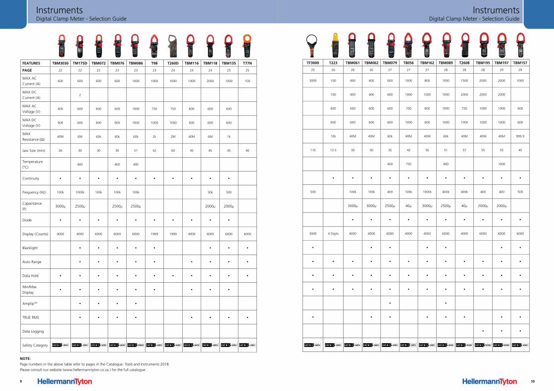
Digital Clamp Meter - Selection GuideInstruments
FEATURES TBM3030 TM175D TBM072 TBM076 TBM086 T98 T260D TBM116 TBM118 TBM135 T77N
PAGE 22 22 22 23 23 23 24 24 24 25 25
MAX AC
Current (A)600 600 600 600 1000 1000 1000 1000 2000 1000 100
MAX DC
Current (A)2
MAX AC
Voltage (V)600 600 600 600 1000 750 750 600 600 600
MAX DC
Voltage (V)600 600 600 600 1000 1000 1000 600 600 600
MAX
Resistance (Ω)40M 6M 60k 60k 60k 2k 2M 40M 6M 1k
Jaw Size (mm) 26 30 30 30 51 42 60 45 45 45 40
Temperature
(°C)400 400 400
Continuity • • • • • • • • • •
Frequency (Hz) 100k 1000k 100k 100k 100k 30k 500
Capacitance
(F)3000µ 2500µ 2500µ 2500µ 2000µ 2000µ
Diode • • • • • • • • • •
Display (Counts) 4000 4000 6000 6000 6000 1999 1999 4000 6000 6000 6000
Blacklight • • • • • • • •
Auto Range • • • • • • • • •
Data Hold • • • • • • • • • • •
Min/Max
Display• • • • • • • • •
AmptipTM • • • •
TRUE RMS • • • • • • • •
Data Logging
Safety Category CAT III 300V CAT III 600VCAT IV 300V CAT III 1000VCAT III 600V CAT III 600V CAT III 600V CAT III 600V CAT III 600V CAT III 600V CAT III 300V
NOTE:
Page numbers in the above table refer to pages in the Catalogue: Tools and Instruments 2018.
Please consult our website (www.hellermanntyton.co.za ) for the full catalogue.
9
Digital Clamp Meter - Selection GuideInstruments
FEATURES TBM3030 TM175D TBM072 TBM076 TBM086 T98 T260D TBM116 TBM118 TBM135 T77N
PAGE 22 22 22 23 23 23 24 24 24 25 25
MAX AC
Current (A)600 600 600 600 1000 1000 1000 1000 2000 1000 100
MAX DC
Current (A)2
MAX AC
Voltage (V)600 600 600 600 1000 750 750 600 600 600
MAX DC
Voltage (V)600 600 600 600 1000 1000 1000 600 600 600
MAX
Resistance (Ω)40M 6M 60k 60k 60k 2k 2M 40M 6M 1k
Jaw Size (mm) 26 30 30 30 51 42 60 45 45 45 40
Temperature
(°C)400 400 400
Continuity • • • • • • • • • •
Frequency (Hz) 100k 1000k 100k 100k 100k 30k 500
Capacitance
(F)3000µ 2500µ 2500µ 2500µ 2000µ 2000µ
Diode • • • • • • • • • •
Display (Counts) 4000 4000 6000 6000 6000 1999 1999 4000 6000 6000 6000
Blacklight • • • • • • • •
Auto Range • • • • • • • • •
Data Hold • • • • • • • • • • •
Min/Max
Display• • • • • • • • •
AmptipTM • • • •
TRUE RMS • • • • • • • •
Data Logging
Safety Category
TF3000 T223 TBM061 TBM062 TBM079 T8056 TBM162 TBM089 T2608 TBM195 TBM197 TBM157
25 26 26 26 27 27 27 28 28 28 29 29
3000 100 400 400 600 1000 800 1000 1500 2000 2000 1000
100 400 400 600 1000 1000 1000 2000 2000 2000
600 600 600 600 700 600 1000 750 1000 1000 600
600 600 600 600 1000 600 1000 1000 1000 1000 600
10k 40M 40M 60k 40M 40M 60k 40M 40M 40M 999.9
110 12.5 30 30 35 42 50 51 57 55 55 45
400 750 400 1000
• • • • • • • • • • •
500 100k 100k 400 100k 1000k 400k 400k 400 400 500
3000µ 3000µ 2500µ 40µ 3000µ 2500µ 40µ 2000µ 2000µ
• • • • • • • • • •
3000 4 Digits 4000 4000 6000 4000 4000 6000 4000 6000 6000 6000
• • • • • • •
• • • • • • • • • • • •
• • • • • • • • • • • •
• • • • • • • • • • • •
• •
• • • • • • • •
• • •
CAT IV 600V CAT III 300V CAT III 600V CAT III 600V CAT III 600V CAT III 600V CAT III 600V CAT IV 600V CAT III 600VCAT IV 1000VCAT IV 1000VCAT III 1000V
10
Insulation Tester - Selection GuideInstruments
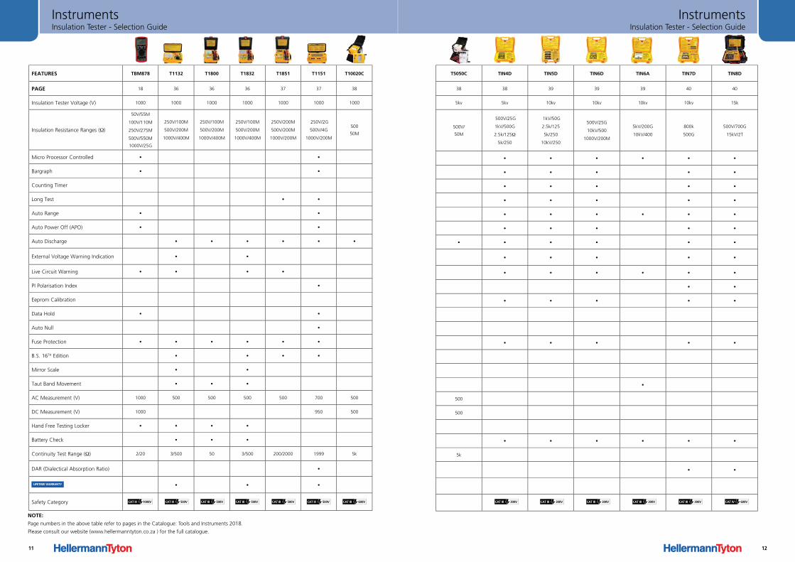
FEATURES TBM878 T1132 T1800 T1832 T1851 T1151 T10020C T5050 TIN4D TIN5D TIN6D TIN6A TIN7D TIN8D
PAGE 18 36 36 36 37 37 38
Insulation Tester Voltage (V) 1000 1000 1000 1000 1000 1000 1000 5kv 5kv 10kv 10kv 10kv 10kv
Insulation Resistance Ranges (Ω)
50V/55M
100V/110M
250V/275M
500V/550M
1000V/25G
250V/100M
500V/200M
1000V/400M
250V/100M
500V/200M
1000V/400M
250V/100M
500V/200M
1000V/400M
250V/200M
500V/200M
1000V/200M
250V/2G
500V/4G
1000V/200M
500
50M
500V/
50M
500V/25GΩ
1kV/500GΩ
2.5k/125Ω,
5k/250Ω
1kV/50G
2.5k/125Ω,
5k/250Ω
10kV/250Ω
500V/25GΩ
10kV/500Ω
1000/200MΩ
5kV/200GΩ
10kV/400Ω
800kΩ
500GΩ
500V/700GΩ
15kV/2TΩ
Micro Processor Controlled • • • • • • • •
Bargraph • • • • • • •
Counting Timer • • • • •
Long Test • • • • • • •
Auto Range • • • • • • • •
Auto Power Off (APO) • • • • • • •
Auto Discharge • • • • • • • • • • • •
External Voltage Warning Indication • • • • • • •
Live Circuit Warning • • • • • • • • • •
PI Polarisation Index • • • • • •
Eeprom Calibration • • • • •
Data Hold • •
Auto Null •
Fuse Protection • • • • • • • • • • •
B.S. 16TH Edition • • • •
Mirror Scale • •
Taut Band Movement • • • •
AC Measurement (V) 1000 500 500 500 500 700 500 500
DC Measurement (V) 1000 950 500 500
Hand Free Testing Locker • • • •
Battery Check • • • • • • • • •
Continuity Test Range (Ω) 2/20 3/500 50 3/500 200/2000 1999 5k 5kΩ
DAR (Dialectical Absorption Ratio) • • •
• • •
Safety CategoryCAT III (V)
300V
CAT III (V)
300V
CAT III (V)
300V
CAT III (V)
300VCAT III 500V CAT III 500V CAT III 500V CAT III 500V CAT III 600V
LIFETIME WARRANTY
CAT III 500VCAT III 1000V
NOTE:
Page numbers in the above table refer to pages in the Catalogue: Tools and Instruments 2018.
Please consult our website (www.hellermanntyton.co.za ) for the full catalogue.
11
Insulation Tester - Selection GuideInstruments
FEATURES T1132 T1800 T1832 T1851 T1151 T10020 T5050C TIN4D TIN5D TIN6D TIN6A TIN7D TIN8D
38 38 39 39 39 40 40
Insulation Tester Voltage 1000V 1000V 1000V 1000V 1000V 1000V 5kv 5kv 10kv 10kv 10kv 10kv 15k
Insulation Resistance Ranges
250V/100MΩ
500V/200MΩ
1000/400MΩ
250V/100MΩ
500V/200MΩ
1000/400MΩ
250V/100MΩ
500V/200MΩ
1000/400MΩ
250V/200MΩ
500V/200MΩ
1000/200MΩ
250V/2GΩ
500V/4GΩ
1000/200MΩ
500V/
50M
500V/
50M
500V/25G
1kV/500G
2.5k/125Ω
5k/250
1kV/50G
2.5k/125
5k/250
10kV/250
500V/25G
10kV/500
1000V/200M
5kV/200G
10kV/400
800k
500G
500V/700G
15kV/2T
Micro Processor Controlled • • • • • • •
Bargraph • • • • • •
Counting Timer • • • • •
Long Test • • • • • • •
Auto Range • • • • • • •
Auto Power Off • • • • • •
Auto Discharge • • • • • • • • • • • •
External Voltage Warning Indication • • • • • • •
Live Circuit Warning • • • • • • • • •
PI Polarisation Index • •
Eeprom Calibration • • • • •
Data Hold •
Auto Null •
Fuse Protection • • • • • • • • • •
B.S. 16TH Tdition • • • •
Mirror Scale • •
Taut Band Movement • • • •
AC V Measurement (V) 500 500 500 500 700 500 500
DC V Measurement 950 500 500
Hand Free Testing Locker • • •
Battery Check • • • • • • • • •
Continuity Test Range (Ω) 3/500 50 3/500 200Ω/ 2000Ω 1999 5kΩ 5k
DAR (Dialectical Absorption Ratio) • • •
MOV (Metal Oxide Varistor)
Safety CategoryCAT III (V)
500V
CAT III (V) 500V
CAT III (V) 500V
CAT III (V) 500V
CAT III (V) 600V
CAT III 300V CAT III 300V CAT III 300V CAT III 300V CAT III 300V CAT IV 600V
12
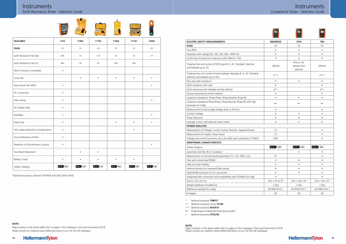
Earth Resistance Tester - Selection GuideInstruments
*
FEATURES T416 T1805 T1105 T1820 T1120 T2000
PAGE 31 31 32 32 32 29
Earth Resistance Test (Ω) 50k 1k 1.2k 2k 2k 1k
Earth Resistance Test (V) 460 30 30 200 200
Micro Processor Controlled •
Long Test • • • • •
Auto Power Off (APO) • •
PC Connection •
Data Saving • •
On Display Help •
Backlight • •
Data Hold • • • •
Test Cables Resistance Compensation • •
Ground Resisting 4 Wire •
Detection of Disturbances Currents • •
Taut Band Movement • •
Battery Check • • • • •
Safety Category
*Optional accessory software TOPVIEW and USB Cable (T416)
CAT III 265V CAT III 150V CAT III 200V CAT III 150VCAT IV 30V CAT II 300V
NOTE:
Page numbers in the above table refer to pages in the Catalogue: Tools and Instruments 2018.
Please consult our website (www.hellermanntyton.co.za ) for the full catalogue.
13
Compliance Tester - Selection GuideInstruments
ELECTRIC SAFETY MEASUREMENTS MACROG3 T419 T60
PAGE 53 53 53
True RMS • • •
Insulation with voltage 50, 100, 250, 500, 1000V DC • • •
Continuity of protective conductors with 200mA / 10A • • •
Tripping time and current of RCDs type B, A, AC Standard, Selective
and Delayed up to 1A200mA
Only A, AC
general and
selective
200mA
Tripping time and current of earth leakage relaystype B, A, AC Standard,
Selective and Delayed up to 10A•*** •***
Non-trip earth resistance • • •
Earth resistance with rods • •
Earth resistance with stakeless testing method •** •**
Ground resistivity by 4-wire method • •
Loop/Line impedance, Phase-Phase, Phase-Neutral, Phase-PE • • •
Loop/Line impedance Phase-Phase, Phase-Neutral, Phase-PE with high
resolution (0.1mΩ)•* •* •*
Measurement of percentage voltage drop on the line • •
Contact Voltage • • •
Phase Sequence • • •
Leakage current with optional clamp meter • • •
POWER ANALYSIS
Measurement of Voltage, Current, Active, Reactive, Apparent Power (1) •
Measurement of Cosphi, Power Factor (1) •
Voltage and current harmonics up to the 49th with calculation of THD% 25th •
ADDITIONAL CHARACTERISTICS
Safety category CAT III 240V CAT III 240V CAT III 300V
Automatic test (Ra, RCD, Insulation) • •
Measurement of environmental parameters (°C, °CF, %RH, Lux) •* *+
Test with remote lead PR400 • • •
Help on screen display • • •
Internal memory for measured data saving • • •
Optical/USB serial port for PC connection • • •
Integrated WiFi connection and compatibility with HTANALYSIS App • •
Size (L x W x H) mm 222 x 16 2x 57 222 x 162 x 57 222 x 162 x 57
Weight (batteries included) Kg 1.2kg 1.2kg 1.2kg
Reference standard for safety IEC/EN61010-1 IEC/EN61010-1 IEC/EN61010-1
IP degree 50 50 50
* Optional accessory TIMP57
** Optional accessory clamp T2100
*** Optional accessory RCDX10
(1) Single-phase or balanced three-phase system
+ Optional accessory HT52/05
NOTE: Page numbers in the above table refer to pages in the Catalogue: Tools and Instruments 2018. Please consult our website (www.hellermanntyton.co.za ) for the full catalogue.
14
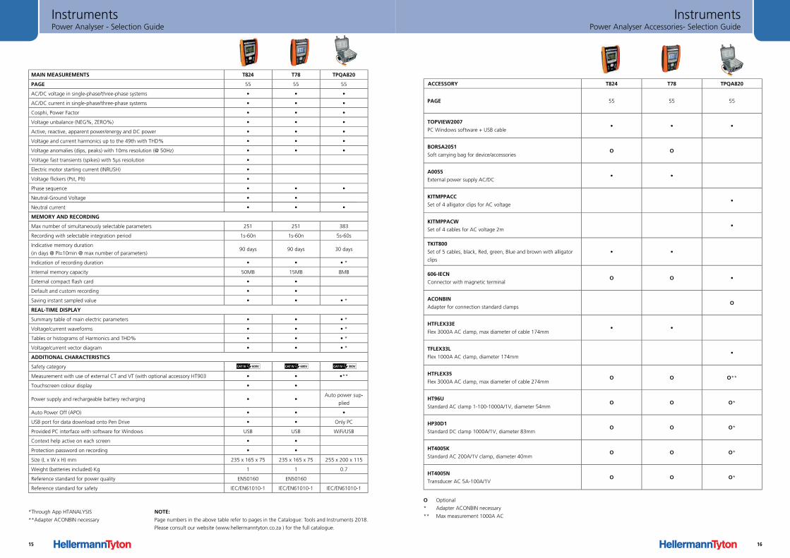
Power Analyser - Selection GuideInstruments
*Through App HTANALYSIS
**Adapter ACONBIN necessary
MAIN MEASUREMENTS T824 T78 TPQA820
PAGE 55 55 55
AC/DC voltage in single-phase/three-phase systems • • •
AC/DC current in single-phase/three-phase systems • • •
Cosphi, Power Factor • • •
Voltage unbalance (NEG%, ZERO%) • • •
Active, reactive, apparent power/energy and DC power • • •
Voltage and current harmonics up to the 49th with THD% • • •
Voltage anomalies (dips, peaks) with 10ms resolution (@ 50Hz) • • •
Voltage fast transients (spikes) with 5µs resolution •
Electric motor starting current (INRUSH) •
Voltage flickers (Pst, Plt) •
Phase sequence • • •
Neutral-Ground Voltage • •
Neutral current • • •
MEMORY AND RECORDING
Max number of simultaneously selectable parameters 251 251 383
Recording with selectable integration period 1s-60n 1s-60n 5s-60s
Indicative memory duration
(in days @ PI=10min @ max number of parameters)90 days 90 days 30 days
Indication of recording duration • • • *
Internal memory capacity 50MB 15MB 8MB
External compact flash card • •
Default and custom recording • •
Saving instant sampled value • • • *
REAL-TIME DISPLAY
Summary table of main electric parameters • • • *
Voltage/current waveforms • • • *
Tables or histograms of Harmonics and THD% • • • *
Voltage/current vector diagram • • • *
ADDITIONAL CHARACTERISTICS
Safety category
Measurement with use of external CT and VT (with optional accessory HT903 • • •**
Touchscreen colour display • •
Power supply and rechargeable battery recharging • •Auto power sup-
plied
Auto Power Off (APO) • • •
USB port for data download onto Pen Drive • • Only PC
Provided PC interface with software for Windows USB USB WiFi/USB
Context help active on each screen • •
Protection password on recording • •
Size (L x W x H) mm 235 x 165 x 75 235 x 165 x 75 255 x 200 x 115
Weight (batteries included) Kg 1 1 0.7
Reference standard for power quality EN50160 EN50160
Reference standard for safety IEC/EN61010-1 IEC/EN61010-1 IEC/EN61010-1
CAT IV 600V CAT IV 600V CAT IV 300V
NOTE:
Page numbers in the above table refer to pages in the Catalogue: Tools and Instruments 2018.
Please consult our website (www.hellermanntyton.co.za ) for the full catalogue.
15
Power Analyser Accessories- Selection GuideInstruments
ACCESSORY T824 T78 TPQA820
PAGE 55 55 55
TOPVIEW2007
PC Windows software + USB cable• • •
BORSA2051
Soft carrying bag for device/accessoriesO O
A0055
External power supply AC/DC• •
KITMPPACC
Set of 4 alligator clips for AC voltage•
KITMPPACW
Set of 4 cables for AC voltage 2m•
TKIT800
Set of 5 cables, black, Red, green, Blue and brown with alligator
clips
• •
606-IECN
Connector with magnetic terminalO O •
ACONBIN
Adapter for connection standard clampsO
HTFLEX33E
Flex 3000A AC clamp, max diameter of cable 174mm• •
TFLEX33L
Flex 1000A AC clamp, diameter 174mm•
HTFLEX35
Flex 3000A AC clamp, max diameter of cable 274mmO O O**
HT96U
Standard AC clamp 1-100-1000A/1V, diameter 54mmO O O*
HP30D1
Standard DC clamp 1000A/1V, diameter 83mmO O O*
HT4005K
Standard AC 200A/1V clamp, diameter 40mmO O O*
HT4005N
Transducer AC 5A-100A/1VO O O*
O Optional
* Adapter ACONBIN necessary
** Max measurement 1000A ACNOTE:
Page numbers in the above table refer to pages in the Catalogue: Tools and Instruments 2018.
Please consult our website (www.hellermanntyton.co.za ) for the full catalogue.
16
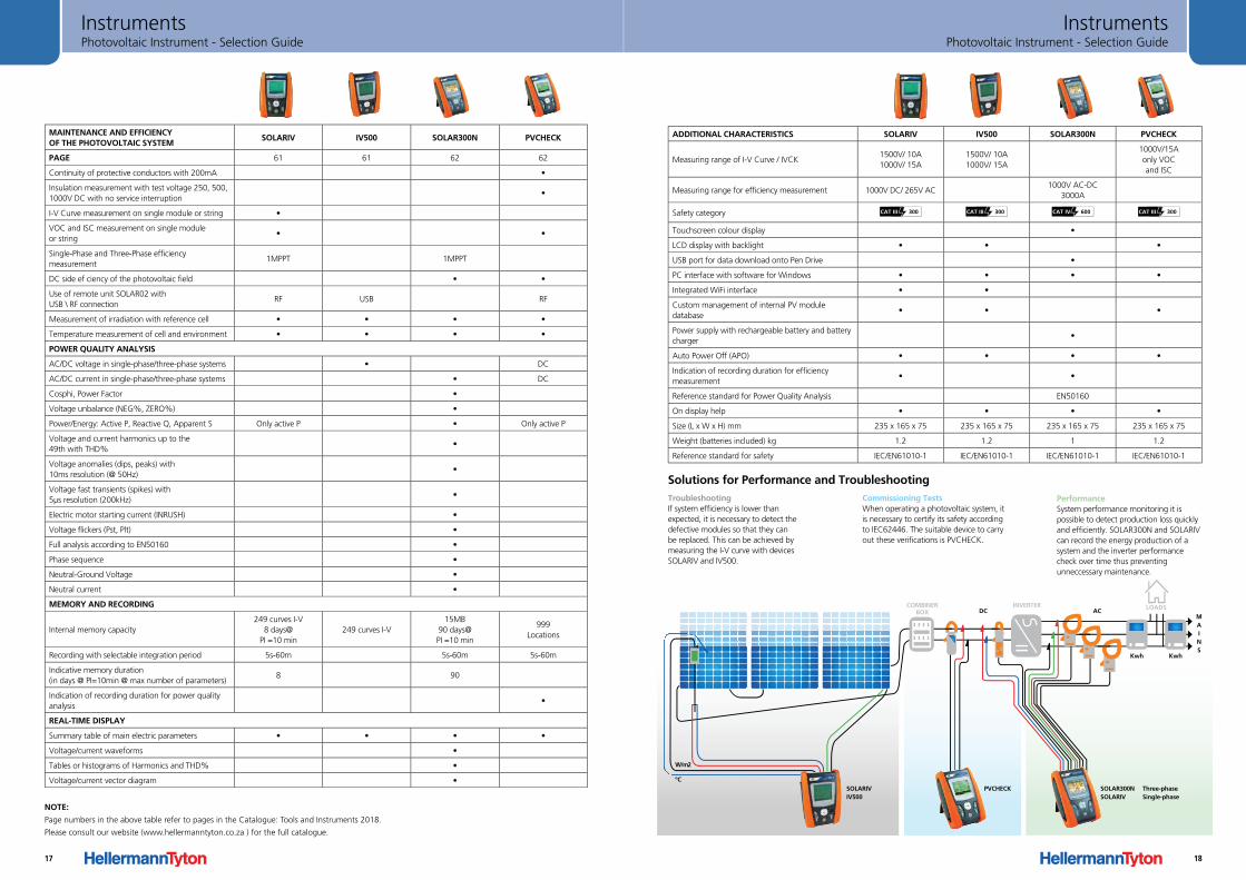
Photovoltaic Instrument - Selection GuideInstruments
MAINTENANCE AND EFFICIENCY OF THE PHOTOVOLTAIC SYSTEM
SOLARIV IV500 SOLAR300N PVCHECK
PAGE 61 61 62 62
Continuity of protective conductors with 200mA •
Insulation measurement with test voltage 250, 500, 1000V DC with no service interruption
•
I-V Curve measurement on single module or string •
VOC and ISC measurement on single module or string
• •
Single-Phase and Three-Phase efficiency measurement
1MPPT 1MPPT
DC side ef ciency of the photovoltaic field • •
Use of remote unit SOLAR02 with USB \ RF connection
RF USB RF
Measurement of irradiation with reference cell • • • •
Temperature measurement of cell and environment • • • •
POWER QUALITY ANALYSIS
AC/DC voltage in single-phase/three-phase systems • DC
AC/DC current in single-phase/three-phase systems • DC
Cosphi, Power Factor •
Voltage unbalance (NEG%, ZERO%) •
Power/Energy: Active P, Reactive Q, Apparent S Only active P • Only active P
Voltage and current harmonics up to the 49th with THD%
•
Voltage anomalies (dips, peaks) with 10ms resolution (@ 50Hz)
•
Voltage fast transients (spikes) with 5µs resolution (200kHz)
•
Electric motor starting current (INRUSH) •
Voltage flickers (Pst, Plt) •
Full analysis according to EN50160 •
Phase sequence •
Neutral-Ground Voltage •
Neutral current •
MEMORY AND RECORDING
Internal memory capacity249 curves I-V
8 days@ PI =10 min
249 curves I-V15MB
90 days@ PI =10 min
999Locations
Recording with selectable integration period 5s-60m 5s-60m 5s-60m
Indicative memory duration(in days @ PI=10min @ max number of parameters)
8 90
Indication of recording duration for power quality analysis
•
REAL-TIME DISPLAY
Summary table of main electric parameters • • • •
Voltage/current waveforms •
Tables or histograms of Harmonics and THD% •
Voltage/current vector diagram •
NOTE:
Page numbers in the above table refer to pages in the Catalogue: Tools and Instruments 2018.
Please consult our website (www.hellermanntyton.co.za ) for the full catalogue.
17
Photovoltaic Instrument - Selection GuideInstruments
ADDITIONAL CHARACTERISTICS SOLARIV IV500 SOLAR300N PVCHECK
Measuring range of I-V Curve / IVCK1500V/ 10A1000V/ 15A
1500V/ 10A 1000V/ 15A
1000V/15Aonly VOC and ISC
Measuring range for efficiency measurement 1000V DC/ 265V AC1000V AC-DC
3000A
Safety category CAT III 300 CAT III 300 CAT IV 600 CAT III 300
Touchscreen colour display •
LCD display with backlight • • •
USB port for data download onto Pen Drive •
PC interface with software for Windows • • • •
Integrated WiFi interface • •
Custom management of internal PV module database
• • •
Power supply with rechargeable battery and battery charger
•
Auto Power Off (APO) • • • •
Indication of recording duration for efficiency measurement
• •
Reference standard for Power Quality Analysis EN50160
On display help • • • •
Size (L x W x H) mm 235 x 165 x 75 235 x 165 x 75 235 x 165 x 75 235 x 165 x 75
Weight (batteries included) kg 1.2 1.2 1 1.2
Reference standard for safety IEC/EN61010-1 IEC/EN61010-1 IEC/EN61010-1 IEC/EN61010-1
TroubleshootingIf system efficiency is lower than expected, it is necessary to detect the defective modules so that they can be replaced. This can be achieved by measuring the I-V curve with devices SOLARIV and IV500.
Solutions for Performance and TroubleshootingCommissioning TestsWhen operating a photovoltaic system, it is necessary to certify its safety according to IEC62446. The suitable device to carryout these verifications is PVCHECK.
PerformanceSystem performance monitoring it is possible to detect production loss quickly and efficiently. SOLAR300N and SOLARIV can record the energy production of a system and the inverter performance check over time thus preventing unneccessary maintenance.
ºC
W/m2
ACDC
KwhKwh
COMBINERBOX
SOLARIVIV500
SOLAR300NSOLARIV
Three-phaseSingle-phase
PVCHECK
MAINS
LOADSINVERTER
18
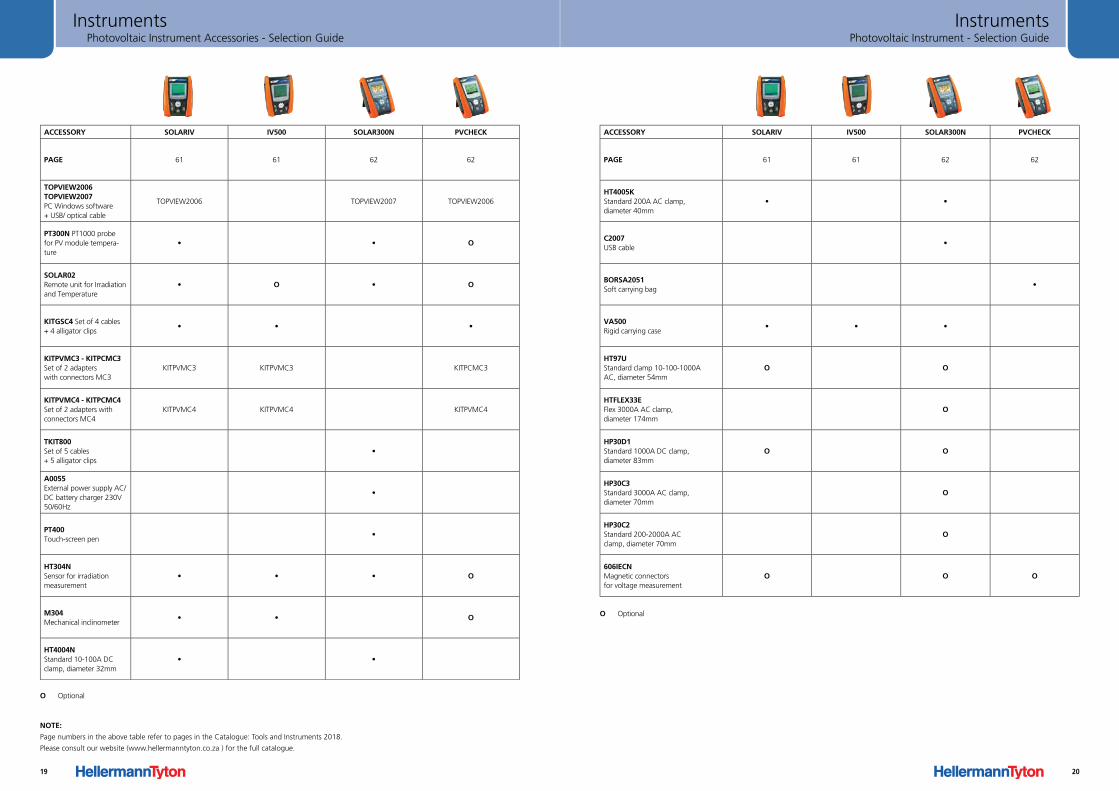
Photovoltaic Instrument Accessories - Selection GuideInstruments
ACCESSORY SOLARIV IV500 SOLAR300N PVCHECK
PAGE 61 61 62 62
TOPVIEW2006TOPVIEW2007PC Windows software+ USB/ optical cable
TOPVIEW2006 TOPVIEW2007 TOPVIEW2006
PT300N PT1000 probefor PV module tempera-ture
• • O
SOLAR02Remote unit for Irradiationand Temperature
• O • O
KITGSC4 Set of 4 cables+ 4 alligator clips
• • •
KITPVMC3 - KITPCMC3Set of 2 adapterswith connectors MC3
KITPVMC3 KITPVMC3 KITPCMC3
KITPVMC4 - KITPCMC4Set of 2 adapters with connectors MC4
KITPVMC4 KITPVMC4 KITPVMC4
TKIT800 Set of 5 cables+ 5 alligator clips
•
A0055External power supply AC/DC battery charger 230V 50/60Hz
•
PT400Touch-screen pen
•
HT304NSensor for irradiation measurement
• • • O
M304Mechanical inclinometer
• • O
HT4004NStandard 10-100A DC clamp, diameter 32mm
• •
O Optional
NOTE:
Page numbers in the above table refer to pages in the Catalogue: Tools and Instruments 2018.
Please consult our website (www.hellermanntyton.co.za ) for the full catalogue.
19
Photovoltaic Instrument - Selection GuideInstruments
ACCESSORY SOLARIV IV500 SOLAR300N PVCHECK
PAGE 61 61 62 62
HT4005KStandard 200A AC clamp,diameter 40mm
• •
C2007USB cable
•
BORSA2051Soft carrying bag
•
VA500Rigid carrying case
• • •
HT97UStandard clamp 10-100-1000AAC, diameter 54mm
O O
HTFLEX33EFlex 3000A AC clamp,diameter 174mm
O
HP30D1Standard 1000A DC clamp,diameter 83mm
O O
HP30C3Standard 3000A AC clamp,diameter 70mm
O
HP30C2Standard 200-2000A ACclamp, diameter 70mm
O
606IECNMagnetic connectorsfor voltage measurement
O O O
O Optional
20
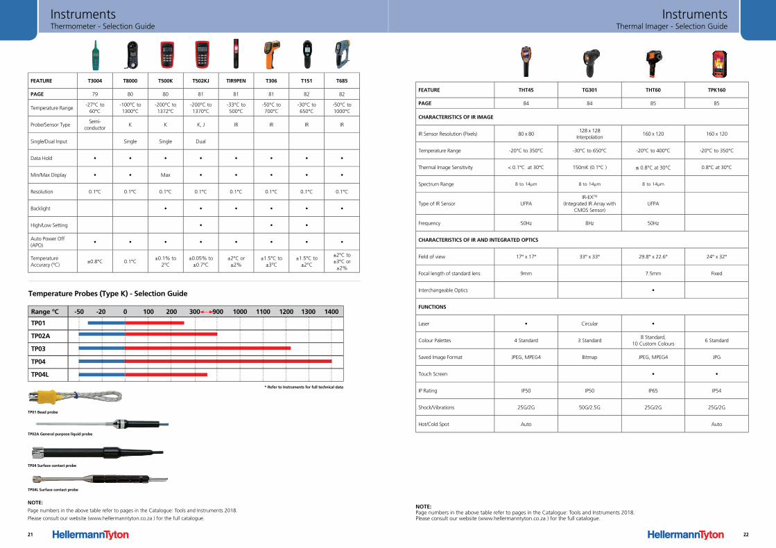
FEATURE T3004 T8000 T500K T502KJ TIR9PEN T306 T151 T685
PAGE 79 80 80 81 81 81 82 82
Temperature Range-27°C to
60°C-100°C to 1300°C
-200°C to 1372°C
-200°C to 1370°C
-33°C to 500°C
-50°C to 700°C
-30°C to 650°C
-50°C to 1000°C
Probe/Sensor TypeSemi-
conductorK K K, J IR IR IR IR
Single/Dual Input Single Single Dual
Data Hold • • • • • • • •
Min/Max Display • • Max • • • • •
Resolution 0.1°C 0.1°C 0.1°C 0.1°C 0.1°C 0.1°C 0.1°C 0.1°C
Backlight • • • • • •
High/Low Setting • • •
Auto Power Off (APO)
• • • • • • • •
Temperature Accuracy (°C)
±0.8°C 0.1°C±0.1% to
2°C±0.05% to
±0.7°C±2°C or
±2%±1.5°C to
±3°C ±1.5°C to
±2°C
±2°C to±3°C or
±2%
Range ºC -50 -20 0 100 200 300 900 1000 1100 1200 1300 1400
TP01
TP02A
TP03
TP04
TP04L
Temperature Probes (Type K) - Selection Guide
TP04 Surface contact probe
TP04L Surface contact probe
TP02A General purpose liquid probe
TP01 Bead probe
* Refer to Instruments for full technical data
Thermometer - Selection GuideInstruments
NOTE:
Page numbers in the above table refer to pages in the Catalogue: Tools and Instruments 2018.
Please consult our website (www.hellermanntyton.co.za ) for the full catalogue.
21
Thermal Imager - Selection GuideInstruments
FEATURE THT45 TG301 THT60 TPK160
PAGE 84 84 85 85
CHARACTERISTICS OF IR IMAGE
IR Sensor Resolution (Pixels) 80 x 80128 x 128
Interpolation160 x 120 160 x 120
Temperature Range -20°C to 350°C -30°C to 650°C -20°C to 400°C -20°C to 350°C
Thermal Image Sensitivity < 0.1°C at 30°C 150mK (0.1°C ) ≤ 0.8°C at 30°C 0.8°C at 30°C
Spectrum Range 8 to 14µm 8 to 14µm 8 to 14µm
Type of IR Sensor UFPAIR-EXTM
(Integrated IR Array with CMOS Sensor)
UFPA
Frequency 50Hz 8Hz 50Hz
CHARACTERISTICS OF IR AND INTEGRATED OPTICS
Field of view 17° x 17° 33° x 33° 29.8° x 22.6° 24° x 32°
Focal length of standard lens 9mm 7.5mm Fixed
Interchangeable Optics •
FUNCTIONS
Laser • Circular •
Colour Palettes 4 Standard 3 Standard8 Standard,
10 Custom Colours6 Standard
Saved Image Format JPEG, MPEG4 Bitmap JPEG, MPEG4 JPG
Touch Screen • •
IP Rating IP50 IP50 IP65 IP54
Shock/Vibrations 25G/2G 50G/2.5G 25G/2G 25G/2G
Hot/Cold Spot Auto Auto
NOTE: Page numbers in the above table refer to pages in the Catalogue: Tools and Instruments 2018. Please consult our website (www.hellermanntyton.co.za ) for the full catalogue.
22


![HellermannTyton Catalogo Canalizacion[1]](https://img.dokumen.tips/doc/110x75/5571fea049795991699bcbd1/hellermanntyton-catalogo-canalizacion1.jpg)