Embed Size (px)
Citation preview

LETTERSPUBLISHED ONLINE: 24 OCTOBER 2016 | DOI: 10.1038/NMAT4782
Instrumented cardiac microphysiological devicesvia multimaterial three-dimensional printingJohan U. Lind1,2†, Travis A. Busbee1,2†, Alexander D. Valentine1,2, Francesco S. Pasqualini1,2,Hongyan Yuan1,2‡, Moran Yadid1,2, Sung-Jin Park1,2, Arda Kotikian1,2, Alexander P. Nesmith1,2,Patrick H. Campbell1,2, Joost J. Vlassak2, Jennifer A. Lewis1,2* and Kevin K. Parker1,2*Biomedical research has relied on animal studies and conven-tional cell cultures for decades. Recently, microphysiologicalsystems (MPS), also known as organs-on-chips, that recapitu-late the structure and function of native tissues in vitro, haveemerged as a promising alternative1. However, current MPStypically lack integrated sensors and their fabrication requiresmulti-step lithographic processes2. Here, we introduce a facileroute for fabricating anewclass of instrumented cardiacmicro-physiological devicesviamultimaterial three-dimensional (3D)printing. Specifically, we designed six functional inks, basedon piezo-resistive, high-conductance, and biocompatible softmaterials that enable integration of soft strain gauge sensorswithin micro-architectures that guide the self-assembly ofphysio-mimetic laminar cardiac tissues. We validated thatthese embedded sensors provide non-invasive, electronicreadouts of tissue contractile stresses inside cell incubatorenvironments. We further applied these devices to study drugresponses, as well as the contractile development of humanstem cell-derived laminar cardiac tissues over four weeks.
Current MPS models of muscle tissue rely on microscopy cou-pled with optical tracking analysis for assessing tissue contrac-tile stress. For instance, muscular thin-film (MTF) assays trackchanges in curvature of soft cantilever substrates induced by thecontraction of a laminar tissue3, and micro-post assays measurethe deflection of pillars supporting a micro-tissue4. Although theseassays have proved valuable for short-term modelling of humandisease and small-scale drug screening applications1,5,6, they are notwell suited for higher-throughput or longer-term studies. More-over, biomimetic microsystems are at present fabricated using softmaterial lithography-based techniques that require multiple steps,masks and dedicated tools4,7–9, which hinders rapid prototyping andcustomization. By contrast,multimaterial 3Dprinting of viscoelasticinks enables a wide range of functional, structural and biologicalmaterials to be patterned and integrated in a single programmablemanufacturing step10–14.
Here, we introduce a fully 3D printed and instrumentedmicrophysiological device that provides continuous electronic read-out of the contractile stress ofmultiple laminar cardiacmicro-tissues(Fig. 1a,b). Each device contains three key features: multilayer can-tilevers, composed of a base layer, an embedded strain sensor, and atissue-guiding layer; electrical interconnects for readout; and eightindependent wells (Fig. 1c–i). The tissue-guiding layer promotesself-assembly of engineered physio-mimetic laminar tissues from
neonatal rat ventricular myocytes (NRVMs) and human inducedpluripotent stem cell-derived cardiomyocytes (hiPS-CMs). Our mi-crophysiological device facilitates tissue culture and non-invasiveanalyses of tissue contractile strength over several weeks, and facili-tates drug studies inside a controlled incubator environment.
To create this integrated device, six materials are patternedsequentially via direct ink writing multimaterial 3D printing.To allow material integration at the microscale, the substratetopology and x–y–z positions of four individually addressablenozzles are determined by an automated calibration process (seeSupplementaryMovie 1). After this calibration, the device is printedin a single continuous procedure (Fig. 1c–i and SupplementaryMovies 2 and 3).
The stress generated by laminar cardiac tissues is limitedto the range 1–15 kPa (refs 5,8). Hence, to match this range,both the thickness and stiffness of each cantilever layer mustbe minimized. Towards this objective, we designed a series ofhighly dilute polymer-based inks. Their low solids content ensurespatterning of thin individual layers (0.5–6.5 µm in thickness).Additionally, by tuning the evaporation rate of the carrier solventsolution, the ink viscosity and corresponding wetting and spreadingbehaviour is controlled to achieve the desired lateral dimensions(Supplementary Figs 1 and 2). Using these inks, 0.5 µm dextranfilms are printed first (Fig. 1c). These serve as biocompatible, water-soluble sacrificial release layers that allow the final cantilevers todetach from the substrate and deflect freely. Next, using dilutethermoplastic polyurethane (TPU) inks, 3-µm-thick cantileverbases, 6.5-µm-thick strain gauge wires and 1.5-µm-thick wirecovers are printed in steps 2–4, respectively (Fig. 1d–f). Thecantilever base and wire covers are printed using an unfilled TPUink, whereas the strain gauge wires are printed using a TPU inkfilled with 25 wt% carbon black nanoparticles (CB:TPU). Theprinted TPU-based features exhibit elastic mechanical propertieswith a Young’s modulus of 1.6MPa (Supplementary Fig. 3), whereasCB:TPU features readily cure to form an elastic piezo-resistivematerial with a Young’s modulus of 8.8MPa and resistivity of1.19� cm (Supplementary Figs 3–7). Several alternative fillers wereinvestigated, including metals particles15 and carbon nanotubes16.However, we found that carbon black imparts the best combinationof ink rheology, low stiffness and sensor hysteresis.
The remainder of the microphysiological device is printedusing concentrated viscoelastic inks optimized for deposition ofself-supporting structures (Supplementary Figs 8 and 9). Using a
1Wyss Institute for Biologically Inspired Engineering, Harvard University, Boston, Massachusetts 02115, USA. 2John A. Paulson School of Engineering andApplied Sciences, Harvard University, Cambridge, Massachusetts 02138, USA. †These authors contributed equally to this work. ‡Present address:Department of Mechanical, Industrial and Systems Engineering, University of Rhode Island, Kingston, Rhode Island 02881, USA.*e-mail: [email protected]; [email protected]
NATUREMATERIALS | VOL 16 | MARCH 2017 | www.nature.com/naturematerials 303
© 2017 Macmillan Publishers Limited, part of Springer Nature. All rights reserved.

LETTERS NATUREMATERIALS DOI: 10.1038/NMAT4782
mm
50
1 20
3 4
Electrical leads &contact pads
μm
Wells & insulationcovers
Tissue guidingmicrofilaments
Ink: shear-thinningsoft PDMS
Ink: shear-thinning Ag:PA
Ink: shear-thinning PDMS
g h i
μm μm
0
mm
4
1 2 3 4mm
1 2 3 4mm
1 2 3 4mm
1 2 3 4
10
0
20
0
20
0
Ink: dilute dextran
Ink: dilute TPU
Step 4 Wire cover
Step 2 Cantilever base
Step 1 Release layer
Step 3 Strain gauge wire
Ink: dilute CB:TPU
Ink: dilute TPU
c
Profiling
μm μm
d e f
3 Contractile stress measured as ΔR0 5
50
0
Time (s)
ΔR (Ω
)
Rref Rsig
1 Anisotropic cardiac tissue 1 Anisotropic cardiac tissue
Gauge w
ire
stre
tch
2 Cantileverdeflection
2 Cantileverdeflection
Ω
Tiss
ue
contra
ction
75 mm
3 Contractile stress measured as ΔR
ba
Step 6 Step 7Step 5
Figure 1 | Device principle and microscale 3D-printing procedure. a, Sketch of the device principle. Contraction of an anisotropic engineered cardiac tissue(1) deflects a cantilever substrate (2), thereby stretching a soft strain gauge embedded in the cantilever. This generates a resistance change proportional tothe contractile stress of the tissue (3). b, The fully printed final device. Insert 1: Confocal microscopy image of immunostained laminar NRVM cardiac tissueon the cantilever surface. Blue, DAPI nuclei stain. White, α-actinin. Scale bar, 10 µm. Insert 2: Still images of a cantilever deflecting upon tissue contraction.Insert 3: Example resistance signal. c–i, Automated printing of the device on a 2 inch× 3 inch glass slide substrate in seven sequential steps. For each step,a corresponding still image from the printing procedure is shown. For steps 1–5, a stylus profiling cross-sectional contour of the cantilever is also shown.c, In print step 1, a 0.5-µm dextran thin-film sacrificial layer is printed. d, In print step 2, a 3 µm TPU thin-film cantilever base is printed. e, In print step 3, a6.5-µm-thick CB:TPU strain sensor loop is added to the cantilever base. f, In print step 4, a 1.5-µm TPU wire cover is added. g, In print step 5, 20-µm-tall,60-µm-wide PDMS microfilaments are printed in slightly overlapping lines. The filaments constitute the top part of the cantilever and guidecardiomyocytes to form anisotropic laminar tissues. h, In print step 6, electrical leads and contact are added using a high-conductivity Ag:PA ink. i, In printstep 7, covers to insulate exposed wires and wells to contain cells and media are printed using PDMS, PLA or ABS (see Supplementary Fig. 10).
viscous polydimethylsiloxane (PDMS) ink (Young’s modulus of1.28MPa, see Supplementary Fig. 3), ∼60-µm-wide filaments arepatterned on top of each cantilever (Fig. 1g). These comprise themajority of the cantilever thickness and serve as direct support
below the physio-mimetic laminar cardiac tissue. Next, electricalleads and contact pads are printed using a high-conductivity, silverparticle-filled, polyamide (Ag:PA) ink (Fig. 1h). Upon drying, theprinted wires exhibit an electrical resistivity of 6.6× 10⁻⁵ � cm
304
© 2017 Macmillan Publishers Limited, part of Springer Nature. All rights reserved.
NATUREMATERIALS | VOL 16 | MARCH 2017 | www.nature.com/naturematerials

NATUREMATERIALS DOI: 10.1038/NMAT4782 LETTERS
c
Action potential propagation velocity
f
ba
d e
0.6
0.4
0.2
0.0
50
0
Hei
ght (
μm)
2000Width (μm)
50
0
Hei
ght (
μm)
2000Width (μm)
50
0
Hei
ght (
μm)
2000Width (μm)
50
0
Hei
ght (
μm)
2000Width (μm)
50
0
μm
2000Width (μm)
50
0μm
2000Width (μm)
50
0
μm
2000Width (μm)
50
0
μm
2000Width (μm)
OO
P (-
)
Spacing
i
3
2
1
0
Vpa
ra/
V orth
o
h
Nor
m. A
P
1
0
Time (ms)0 200
1
0
Time (ms)0 200
1
0
Time (ms)0 200
1
0
Time (ms)0 200
Vortho = 35 cm s−1 Vortho = 13 cm s−1 Vortho = 10 cm s−1 Vortho = 23 cm s−1
V para
= 3
7 cm
s−1
V para
= 3
5 cm
s−1
V para
= 19
cm
s−1
V para
= 2
5 cm
s−1
Initiationpoint g
Microfilaments guidingtissue self-organization
∗
40 60 80 100
Filament spacing (μm)
40 60 80 100
Filament spacing (μm)
Sarcomere orientationalorder parameter
xy
Spacing 40 μm Spacing 60 μm Spacing 80 μm Spacing 100 μm
Spacing 40 μm Spacing 60 μm Spacing 80 μm Spacing 100 μm
Spacing 40 μm Spacing 60 μm Spacing 80 μm Spacing 100 μm
xz
tmax = 29 ms
Start,t = 0
Start,t = 0
Start,t = 0
Start,t = 0
tmax = 47 ms tmax = 25 mstmax = 21 ms
Figure 2 | Micro-grooves guide cardiomyocyte self-assembly into anisotropic engineered tissues. a, Spacing of soft PDMS microfilaments. b, Sketch ofmicrofilaments guiding self-assembly of engineered cardiac tissue. c, Stylus profilometer contours of substrates with filaments printed at 40, 60, 80 and100 µm spacing. d, Sarcomere OOP of laminar NRVM tissues developed on substrates with 40 (n=9), 60 (n= 13), 80 (n=8) and 100 µm (n= 10)filament spacing. Error bars are standard error of the mean (s.e.m.), ∗,P<0.05. e,f, Representative confocal images from OOP data set z-projection (e) andx–z line scan (f). Blue, DAPI nuclei stain. White, α-actinin. Scale bars, 10 µm. g, Ratio between action potential (AP) propagation speed parallel andorthogonal to the grooves for laminar NRVM tissue developed on substrates with 40, 60, 80 and 100 µm filament spacing, (n≥3). Individual data pointsincluded (circles). Error bars are s.e.m. h, Representative activation time heat maps for AP data set, overlaid with wide-field microscope image of thesamples as guide to the eye. Scale bars, 0.8mm. Activation times normalized to maximum observed activation (tmax, red), to account for tissue sourcevariation. 2Hz electrical point stimulation is applied in top-left corner of samples. Mean observed propagation speed parallel (Vpara) and orthogonal(Vortho) to grooves is shown as vectors. i, Normalized AP traces at four corners of activation map samples. Blue, at AP initiation corner. Red, at tmax-corner.Black, corner parallel to grooves. Green, corner orthogonal to grooves.
(Supplementary Fig. 4), which ensures that the primary electricalresistance of the final device arises from the embedded CB:TPUstrain gauges. Finally, the wire leads are covered with an insulatinglayer, and eight individually addressable wells are printed usingeither a PDMS ink or biocompatible rigid thermoplastic polymerssuch as polylactic acid (PLA) or acrylonitrile butadiene styrene(ABS). The rigid polymers can be preferable for drug studyapplications, as they are less prone to bulk absorption ofhydrophobic drugs than PDMS17 (Fig. 1i and SupplementaryFig. 10). After printing, the devices are cured at 100 ◦C andsubsequently seeded with cardiomyocytes, which self-assemble intolaminar tissues mimicking the structure of the native heart.
The musculature of the heart is composed of highly organized,structurally and electrically anisotropic layers18. To recapitulate thisarchitecture in vitro, we printed a range of grooved microstructuresby varying the spacing between curved ∼20 µm × 60 µm
(height× width) filaments and assessed their ability to guidethe self-assembly of anisotropic laminar NRVM tissues (Fig. 2).We evaluated the degree of tissue structural anisotropy usingimmunofluorescent imaging of sarcomeric α-actinin and quan-tification of the sarcomere orientational order parameter (OOP)(Fig. 2a–f and Supplementary Fig. 11)19. All substrates showed anOOP > 0.2, indicative of nonrandom sarcomere alignment. Thehighest OOP∼0.5 was observed for a 60 µm filament spacing. Simi-larly, a 60 µm filament spacing gave rise to the highest degree of elec-trophysiological anisotropy in the laminar NRVM tissues (Fig. 2g–iand Supplementary Movies 4–7). For this spacing, action potentialpropagation was 2.7 times faster parallel to the grooves compared tothe transverse direction. These data are in agreement with the longi-tudinal to transverse velocity ratio of 2.1 observed in the native ven-tricle18. Also, these anisotropic laminar tissues gave rise to unidirec-tional and concerted cantilever deflection and exhibited the highest
NATUREMATERIALS | VOL 16 | MARCH 2017 | www.nature.com/naturematerials
© 2017 Macmillan Publishers Limited, part of Springer Nature. All rights reserved.
305

LETTERS NATUREMATERIALS DOI: 10.1038/NMAT4782
ε
ε
CB:TPU
Time (s) Time (s)
Time (s) Time (s)
εε
ε
= 10−3, 1 Hzy = 2.56xR2 = 0.99
−1012345
a b c d
e f
i j
g hΔR
/R0
(×10
−3)
ΔR/R
0 (×
10−3
)ΔR
/R0
(×10
−4)
ΔR/R
0 (×
10−3
)
ΔR/R
0 (×
10−3
)
ε= ΔL/L0 (×10
−3)σ
(kPa)
σ(kPa)
ε = ΔL/L0 (×10−3)
ΔR/R0 ΔR/R0
ΔR/R0 = GF ×
Neutral plane
Radiusof curvature
z−1012345
1
3
4
0
4
12
0
8s
Gauge signal
Ω
Ω
60 cycles
2
Optical trackingGauge signal10
0
3
0
2 ‘Systole’
1 ‘Diastole’
100 nMNo isoproterenol
0
10
0
1
0
1
Conc. verapamil (M)
10 μMNo verapamil
0
201 Hz 1 Hz 2 Hz 2 Hz
NRVM hiPS-CM
Time (s) Time (s) Time (s) Time (s)
‘Diastole’1
2 ‘Systole’
0 20 50 7010 4030 60
1
3
4
0
2
1
2
3
04 6 8 10 0.0 0.2 0.4 0.6 0.8 1.0
topεtissueσ
gaugeε
0 4010 20 30 106 84
41 2 3 41 2 3
(kPa
) σ
(kPa
) σ
10−11 10−9 10−7 10−5
Conc. isoproterenol (M) 41 2 3 41 2 3 10−11 10−9 10−7 10−5(
−
min
)/(
max
− m
in)
σσ
σσ
( −
m
in)/
( m
ax−
min
)σ
σσ
σ
= C ×(Zn.p. − Zgauge) × GF
× (ΔR/R0)1tissueσ
Figure 3 | CB:TPU gauge factor, sensor readout and example drug-dose studies. a, Sketch of Instron test set-up for determining CB:TPU gauge factor (GF).b–d, Relative change in CB:TPU resistance upon triangular cyclic straining to 0.1% at 1 Hz. In c the dark grey line is the observed relative resistance changeand the red dotted line is the strain applied. d, Relative resistance change versus applied strain. Orange dotted line indicates a linear fit to part of the cycleswith increasing strain, yielding a gauge factor of 2.56. e, Wide-field microscope images of cantilever bending upon tissue contraction. Minimum deflectioncorresponds to cardiac diastole (1) and peak deflection corresponding to systole (2). f, Sketch of the mechanical model used to convert change in gaugeresistance to stress generated by the tissue, through a linear conversion factor C as described in Supplementary Information. g,h, Relative resistancechanges (left axis) and corresponding calculated tissue twitch stress (right axis) recorded from spontaneously beating cantilever. The blue dotted line in hindicates stress determined independently by optical tracking of the cantilever radius of curvature. i, Representative traces of twitch stress generated by alaminar NRVM tissue when tissue is exposed to verapamil and corresponding dose–response curve (n=4). Error bars are s.e.m., stress normalizedbetween maximal and minimal values, tissue paced at 1 Hz, apparent EC50 1.12× 10⁻⁶ M. Individual data points included (circles). j, Representative tracesof twitch stress generated by a laminar hiPS-CM tissue when exposed to isoproterenol and corresponding dose–response curve, (n= 10). Error bars ares.e.m., stress normalized between maximal and minimal values, tissue paced at 2Hz, apparent EC50 2.74× 10⁻⁹ M.
contractile stresses in the final devices (Supplementary Figs 12–14).Collectively, these results demonstrate that our printing techniquecan be employed to engineer laminar cardiac tissues with a range ofordered architectures. Notably, the OOP and electrophysiology dataclosely matched values obtained using semi-manual micro-contactprinting and moulding techniques7,20,21.
To accurately measure the stress exerted by the physio-mimeticlaminar cardiac tissues, the embedded strain gauges within eachcantilever must produce a reliable and detectable signal. Wetherefore evaluated the electro-mechanical properties of CB:TPUin a series of uniaxial strain tests (Fig. 3a–d and SupplementaryFigs 5–7). To mimic the strains exerted by tissue contraction,1–3Hz triangular strains of 0.1% were applied to CB:TPU gauges.In this strain range, the gauges exhibited a linear strain–resistancerelationship with limited hysteresis and a corresponding gaugefactor of 2.51± 0.09. In order to accurately convert resistancesignals to stresses generated by the laminar cardiac tissues, weestablished a mechanical model of the cantilevers based on amultilayer version of Stoney’s equation (Fig. 3e,f and SupplementaryInformation). The mechanical model relies on the dimensions andYoung’s moduli of each layer of the cantilever as well as the CB:TPUgauge factor. The model provides linear conversion factors betweenthe relative changes in gauge resistance, changes in cantilever radiusof curvature and, in turn, the longitudinal stresses generated bythe laminar cardiac tissues. Applying these conversion factors,
we obtained tissue twitch stress (σ ), the differences between thesystolic and diastolic stress, in the range of 7–15 kPa for laminarNRVM tissues, akin to prior reports3,7. To further verify the model,we compared the sensor readout with stress values concurrentlyobtained through optical tracking of cantilever deflection, andobtained highly similar stress values (Fig. 3g,h and SupplementaryFigs 12 and 13 and Supplementary Movies 8–11). However,we observed one discrepancy between the optical tracking andelectrical readout: at the initiation of tissue contraction, a smalldecrease in gauge resistance is seen, prior to the increase causedby cantilever deflection. We attribute this decrease to a brief axialcompression of the gauge wire occurring during initial tissuecontraction, while cantilever deflection is counteracted by inertialand viscous forces. Notably, this observation does not influencetissue twitch stress values. Together, these results demonstrate thatthe CB:TPU strain gauges embedded in our fully printed platformprovide reliable readouts of tissue contractile stress.
Data acquisition from cardiac microphysiological systems basedon optical readout is laborious, requires dedicated microscopy set-ups and semi-automated image analysis software, and is limited bythe image readout file sizes4,5. By contrast, our fully printed and in-strumented cardiac devices provide a direct non-invasive electronicreadout of contractile stresses. Therefore, we could perform dose–response studies of drugs that influence contraction strength or beatrate directly inside a cell incubator, an ideal in vitro environment
306
© 2017 Macmillan Publishers Limited, part of Springer Nature. All rights reserved.
NATUREMATERIALS | VOL 16 | MARCH 2017 | www.nature.com/naturematerials
NATUREMATERIALS DOI: 10.1038/NMAT4782 LETTERSDay 2
a
d
h ij
k
e f g
b c
(kPa
)
0
12
Spon
tane
ous
beat
rate
(Hz)
0
10
Time (s) Time (s) Time (s)
Day 14 Day 28
Day 2
0
Days after seedingDay 28 Days after seeding
0.7
Days after seedingDays after seeding
Sarc
. len
gth
(μm
)
SPD
(-)
OO
P (-
)1
21
0
10−10 10−8 10−6 10−4
1
0
1
Conc. verapamil (M)
10−11 10−9 10−7 10−5
Conc. isoproterenol (M)
3
1.5 Hz
1.5 Hz
∗
∗∗
Micro-pin
2
21 43 21 4321 43 282014842 2820148420
1.4
2 2814 2 2814Days after seeding
2 28141.5
1.85
0
0.35
(kPa
) σ
( −
m
in)/
( m
ax−
min
)σ
σσ
σ(
−
min
)/(
max
− m
in)
σσ
σσ
σ
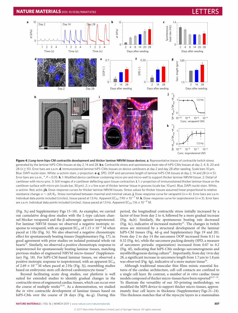
Figure 4 | Long-term hips-CM contractile development and thicker laminar NRVM tissue devices. a, Representative traces of contractile twitch stressgenerated by the laminar hiPS-CMs tissues at day 2, 14 and 28. b,c, Contractile stress and spontaneous beat rate of hiPS-CMs tissues at day 2, 4, 8, 20 and28 (n≥ 10). Error bars are s.e.m. d, Immunostained laminar hiPS-CMs tissues on device cantilevers at day 2 and day 28 after seeding. Scale bars 10 µm.Blue: DAPI nuclei stain. White: α-actinin stain, z-projection. e–g, SPD, OOP and sarcomere length of laminar hiPS-CM tissues at day 2, 14 and 28 (n=5).Error bars are s.e.m., ∗,P<0.05. h, 1: Modified device cantilever containing micro-pin and micro-well to support thicker laminar NRVM tissue. 2: Detail ofcantilever with micro-pins. 3: Still images of a cantilever deflecting upon tissue contraction. i, 1: z-projection of immunostained thicker laminar tissue on thecantilever surface with micro-pin (scale bar, 30 µm). 2: x–z line scan of thicker laminar tissue in grooves (scale bar, 10 µm). Blue, DAPI nuclei stain. White,α-actinin. Red, actin. j,k, Dose–response curves for thicker laminar NRVM tissues. Stress values for thicker tissues assumed linear proportional to relativeresistance change: σ∼1R/R0. Stress normalized between maximal and minimal values. j, Dose–response curve for verapamil (n=4). Error bars are s.e.m.Individual data points included (circles), tissue paced at 1.5Hz. Apparent EC50 7.90× 10⁻⁷ M. k, Dose–response curve for isoproterenol (n=3). Error barsare s.e.m. Individual data points included (circles), tissue paced at 1.5Hz. Apparent EC50 1.16× 10⁻⁹ M.
(Fig. 3i,j and Supplementary Figs 15–18). As examples, we carriedout cumulative drug-dose studies with the L-type calcium chan-nel blocker verapamil and the β-adrenergic agonist isoproterenol.For laminar NRVM tissues we observed a negative inotropic re-sponse to verapamil, with an apparent EC50 of 1.15×10⁻⁶ Mwhenpaced at 1Hz (Fig. 3i). We also observed a negative chronotropiceffect for spontaneously beating tissues (Supplementary Fig. 17), ingood agreement with prior studies on isolated postnatal whole rathearts22. Similarly, we observed a positive chronotropic response toisoproterenol for spontaneously beating laminar tissues, matchingprevious studies of engineered NRVM micro-tissues4 (Supplemen-tary Fig. 18). For hiPS-CM-based laminar tissues, we observed apositive inotropic response to isoproterenol, with an apparent EC50of 2.69× 10⁻⁹ M when paced at 2Hz (Fig. 3j), resembling studiesbased on embryonic stem cell-derived cardiomyocyte tissue23.
Beyond facilitating acute drug studies, our platform is wellsuited for extended studies to identify gradual changes in thecontractile stress of engineered cardiac tissues, which can occur overthe course of multiple weeks23,24. As a demonstration, we studiedthe in vitro contractile development of laminar tissues based onhiPS-CMs over the course of 28 days (Fig. 4a–g). During this
period, the longitudinal contractile stress initially increased by afactor of four from day 2 to 4, followed by a more gradual increase(Fig. 4a,b). Similarly, the spontaneous beating rate decreased(Fig. 4c), indicative of increased maturity25. The changes in twitchstress are mirrored by a structural development of the laminarhiPS-CM tissues (Fig. 4d–g and Supplementary Figs 19 and 20).From day 2 to day 14 the sarcomere OOP increased from 0.11 to0.32 (Fig. 4e), while the sarcomere packing density (SPD, a measureof sarcomere periodic organization) increased from 0.07 to 0.2(Fig. 4f), indicating that hiPS-CMs undergo sarcomerogenesis andmyofibrillogenesis during culture19. Importantly, from day 14 to day28, a significant increase in sarcomere length from 1.7 µm to 1.8 µmwas observed (Fig. 4g), indicative of a more mature tissue26.
Although traditional muscular thin films mimic essential fea-tures of the cardiac architecture, cell–cell contacts are confined toa single cell layer. By contrast, a number of in vitro cardiac tissuemodels composed of thickermicro-tissues have been reported24,27–29.To illustrate the versatility of our 3D-printing methodology, wemodified the MPS device to support thicker micro-tissues, approx-imately four cell layers in thickness (Supplementary Figs 21–24).This thickness matches that of the myocyte layers in a mammalian
NATUREMATERIALS | VOL 16 | MARCH 2017 | www.nature.com/naturematerials
© 2017 Macmillan Publishers Limited, part of Springer Nature. All rights reserved.
307

LETTERS NATUREMATERIALS DOI: 10.1038/NMAT4782
heart (that is, ∼4 cells in thickness per layer, each layer separatedby connective tissue)30. To balance the increased contractile stressandmitigate tissue delamination, we printed thicker cantilevers thatcontained∼100-µm-tallmicro-pin arrayswith tunable areal density(Fig. 4h,i and Supplementary Movies 13–15). Despite these modifi-cations to both the cardiac tissue and cantilevers, the tissue remainsorders of magnitude softer than the substrate. Hence, the basicassumptions of the mechanical model remain valid, and the sensorsignal is directly proportional to mean tissue stress (see Supplemen-tary Information). We carried out proof-of-principle isoproterenoland verapamil drug studies to illustrate the functional relevanceof these thicker NRVM-based tissues (Fig. 4j,k). We observed theexpected positive and negative inotropic responses with apparentEC50 values comparable to earlier data from engineered 3D NRVMtissues and isolated postnatal whole rat hearts22,29.
Through multimaterial 3D printing of a series of customizedinks, we demonstrated the automated design and fabrication ofinstrumented cardiac microphysiological devices. The integratedsensors drastically simplify data acquisition and long-term func-tional studies. Leveraging the ability to track the temporal de-velopment in tissue mechanics will enable new insights into tis-sue morphogenesis, pathogenesis, and drug-induced structural andfunctional remodelling. Our digital manufacturing approach is ver-satile, allowing for fabrication of a range of instrumented micro-physiological devices. Notably, our approach facilitates rapid cus-tomization to match device geometries, mechanical and biochemi-cal properties to a specific diseased state or a unique patient-derivedcell source. Our programmable microfabrication approach opensnew avenues for in vitro tissue engineering, toxicology and drugscreening research.
MethodsMethods and any associated references are available in the onlineversion of the paper.
Received 21 January 2016; accepted 23 September 2016;published online 24 October 2016
References1. Bhatia, S. N. & Ingber, D. E. Microfluidic organs-on-chips. Nat. Biotechnol. 32,
760–772 (2014).2. Mammoto, A. et al . Control of lung vascular permeability and
endotoxin-induced pulmonary oedema by changes in extracellular matrixmechanics. Nat. Commun. 4, 1759 (2013).
3. Feinberg, A. W. et al . Muscular thin films for building actuators and poweringdevices. Science 317, 1366–1370 (2007).
4. Boudou, T. et al . A microfabricated platform to measure and manipulate themechanics of engineered cardiac microtissues. Tissue Eng. A 18,910–919 (2011).
5. Wang, G. et al . Modeling the mitochondrial cardiomyopathy of Barthsyndrome with induced pluripotent stem cell and heart-on-chip technologies.Nat. Med. 20, 616–623 (2014).
6. Hinson, J. T. et al . Titin mutations in iPS cells define sarcomere insufficiency asa cause of dilated cardiomyopathy. Science 349, 982–986 (2015).
7. Agarwal, A. et al . Micropatterning alginate substrates for in vitrocardiovascular muscle on a chip. Adv. Funct. Mater. 23, 3738–3746 (2013).
8. Grosberg, A., Alford, P. W., McCain, M. L. & Parker, K. K. Ensembles ofengineered cardiac tissues for physiological and pharmacological study: hearton a chip. Lab Chip 11, 4165–4173 (2011).
9. Park, S.-J. et al . Phototactic guidance of a tissue-engineered soft-robotic ray.Science 353, 158–162 (2016).
10. Lewis, J. A. Direct ink writing of 3D functional materials. Adv. Funct. Mater. 16,2193–2204 (2006).
11. Hardin, J. O., Ober, T. J., Valentine, A. D. & Lewis, J. A. Microfluidic printheadsfor multimaterial 3D printing of viscoelastic inks. Adv. Mater. 27,3279–3284 (2015).
12. Sun, K. et al . 3D printing of interdigitated Li-Ion microbattery architectures.Adv. Mater. 25, 4539–4543 (2013).
13. Miller, J. S. et al . Rapid casting of patterned vascular networks for perfusableengineered three-dimensional tissues. Nat. Mater. 11, 768–774 (2012).
14. Kolesky, D. B., Homan, K. A., Skylar-Scott, M. A. & Lewis, J. A.Three-dimensional bioprinting of thick vascularized tissues. Proc. Natl Acad.Sci. USA 113, 3179–3184 (2016).
15. Matsuhisa, N. et al . Printable elastic conductors with a high conductivity forelectronic textile applications. Nat. Commun. 6, 7461 (2015).
16. Lipomi, D. J. et al . Skin-like pressure and strain sensors based on transparentelastic films of carbon nanotubes. Nat. Nanotech. 6, 788–792 (2011).
17. Berthier, E., Young, E. W. & Beebe, D. Engineers are from PDMS-land,biologists are from polystyrenia. Lab Chip 12, 1224–1237 (2012).
18. Kléber, A. G. & Rudy, Y. Basic mechanisms of cardiac impulse propagation andassociated arrhythmias. Physiol. Rev. 84, 431–488 (2004).
19. Pasqualini, F. S., Sheehy, S. P., Agarwal, A., Aratyn-Schaus, Y. & Parker, K. K.Structural phenotyping of stem cell-derived cardiomyocytes. Stem Cell Rep. 4,340–347 (2015).
20. Feinberg, A. W. et al . Controlling the contractile strength of engineered cardiacmuscle by hierarchal tissue architecture. Biomaterials 33, 5732–5741 (2012).
21. Sheehy, S. P. et al . Quality metrics for stem cell-derived cardiac myocytes.Stem Cell Rep. 2, 282–294 (2014).
22. OštIádalová, I. et al . Early postnatal development of contractile performanceand responsiveness to Ca2+, verapamil and ryanodine in the isolated rat heart.J. Mol. Cell. Cardiol. 25, 733–740 (1993).
23. Zhang, D. et al . Tissue-engineered cardiac patch for advanced functionalmaturation of human ESC-derived cardiomyocytes. Biomaterials 34,5813–5820 (2013).
24. Zimmermann, W. H. et al . Three-dimensional engineered heart tissue fromneonatal rat cardiac myocytes. Biotechnol. Bioeng. 68, 106–114 (2000).
25. Reiser, P. J., Portman, M. A., Ning, X.-H. & Moravec, C. S. Human cardiacmyosin heavy chain isoforms in fetal and failing adult atria and ventricles.Am. J. Physiol. 280,H1814–H1820 (2001).
26. Lundy, S. D., Zhu, W-Z., Regnier, M. & Laflamme, M. A. Structural andfunctional maturation of cardiomyocytes derived from human pluripotentstem cells. Stem Cells Dev. 22, 1991–2002 (2013).
27. Nunes, S. S. et al . Biowire: a platform for maturation of human pluripotentstem cell-derived cardiomyocytes. Nat. Methods 10, 781–787 (2013).
28. Xiao, Y. et al . Microfabricated perfusable cardiac biowire: a platform thatmimics native cardiac bundle. Lab Chip 14, 869–882 (2014).
29. Zimmermann, W.-H. et al . Tissue engineering of a differentiated cardiacmuscle construct. Circ. Res. 90, 223–230 (2002).
30. LeGrice, I. J. et al . Laminar structure of the heart: ventricular myocytearrangement and connective tissue architecture in the dog. Am. J. Physiol. 269,H571–H582 (1995).
AcknowledgementsThe authors thank L. K. Sanders for her work on photography and time-lapse movies,J. A. Goss for his assistance with fabrication of the device holder and J. Minardi for hisdevelopment of Mecode, and his help with machine automation. This work wasperformed in part at the Center for Nanoscale Systems (CNS), a member of the NationalNanotechnology Infrastructure Network (NNIN), which is supported by the NationalScience Foundation under NSF award no. ECS-0335765. CNS is part of HarvardUniversity. This work was also supported by the National Center For AdvancingTranslational Sciences of the National Institutes of Health under Award NumberUH3TR000522, the US Army Research Laboratory and the US Army Research Officeunder Contract No. W911NF-12-2-0036, the Air Force Research Laboratory underContract No. FA8650-09-D-5037-0004, and the Harvard University Materials ResearchScience and Engineering Center (MRSEC) award no. DMR-1420570. J.U.L. gratefullyacknowledges support from the Villum Foundation. J.A.L. gratefully acknowledgessupport from the Office of Naval Research, Vannevar Bush National Security Science andEngineering Faculty Fellowship (Award No. N00014-16-1-2823).
Author contributionsJ.U.L., T.A.B., J.A.L. and K.K.P. designed the study. J.U.L. and T.A.B. designed the device.T.A.B. coded the 3D-print procedure and automation. J.U.L., T.A.B., A.K. and A.D.V.developed and characterized the printable materials. J.U.L., A.D.V. and T.A.B., optimizedand printed devices. P.H.C. performed NRVM harvesting and prepared culturing media.J.U.L., M.Y. and A.P.N. performed NRVM culture, drug-dose experiments, and dataanalysis. M.Y. and J.U.L. conducted hiPS-CM culture, experiments and data analysis.F.S.P. and J.U.L. performed tissue staining, confocal imaging, and OOP analysis. S.-J.P.and J.U.L. conducted optical mapping experiments and analysis. H.Y. and J.J.V. developedthe mechanical model of the device. J.U.L., T.A.B., J.A.L. and K.K.P. prepared illustrationsand wrote the manuscript. F.S.P. and A.D.V. contributed to writing the manuscript.
Additional informationSupplementary information is available in the online version of the paper. Reprints andpermissions information is available online at www.nature.com/reprints.Correspondence and requests for materials should be addressed to J.A.L. or K.K.P.
Competing financial interestsThe authors declare no competing financial interests.
308
© 2017 Macmillan Publishers Limited, part of Springer Nature. All rights reserved.
NATUREMATERIALS | VOL 16 | MARCH 2017 | www.nature.com/naturematerials

NATUREMATERIALS DOI: 10.1038/NMAT4782 LETTERSMethodsInk formulations. The following ink formulations were used: dextran ink:10 gml−1 dextran (Sigma-Aldrich) was dissolved in 75:25 v:v, water: isopropanol.TPU ink: TPU 15 wt% Elastollan 35A (BASF) dissolved in 4:1 v:vtetrahydrofuran:dimethylformamide. CB:TPU ink: TPU 15 wt% Elastollan 35A,5 wt% carbon black (Vulcan XC72R, Cabot) dissolved in 4:1 v:vtetrahydrofuran:dimethylformamide. Ag:Pa ink: 50 g silver flakes (5–8 µm) mixedwith 5.2 g 30 wt% versamid 973 solution (BASF) dissolved in pentanol, mixed withan additional 2.72 g of pentanol. Soft PDMS Ink: SE1700 (Dow-Corning) with 1:25curing agent based ratio was applied for cantilever covers, micro-pins andmicro-wells. Rigid PDMS ink: SE1700 (Dow-Corning), with 1:10 curing agentweight ratio, mixed 1:5 wt:wt with Sylgard 184 1:10 curing agent weight ratio(Dow-Corning) is used for wells and covers, or as gasket adhesive below PLA orABS wells and covers.
Print procedure with integrated profiling. Printing was carried out using athree-axis motion-controlled stage (Aerotech) with four independent z-axes.Prior to printing, a custom automation system was applied to determine thesubstrate topology and relative x–y–z nozzle positions using an integrated laserprofilometer, three CCD micrometers (Keyence), and custom machined fixtures.G-code generation and custom automation scripts were programmedusing open-sourced Python libraries (Mecode). Extrusion was carried outusing syringes, dispense tips, and a digital pneumatic regulator (EFD). Dispensetip diameters: TPU ink: 100 µm, CB:TPU ink: 200 µm, Ag:PA ink: 250 µm, SoftPDMS ink: 30 µm, Rigid PDMS ink: 410 µm. For dextran ink a refillablecontact-pressure sensitive pen (0.7mm tip, Montana) was utilized asdeposition nozzle.
Device cell seeding and culture. Prior to cell seeding, devices were sterilized byultraviolet–ozone exposure for 8min. Subsequently, wells were incubated with a50 µgml−1 solution of fibronectin (BD Biosciences) in PBS for 1 h. Fibronectinsolution was aspirated and wells seeded with either primary NRVMs at a seedingdensity of 140 k cm−2 in 10% FBS in media 199 (Life Technologies) or hiPS-CMs(Cor4U, Axiogenesis) at 220 k cm−2 in designated Commercial Cor4U media(Axiogenesis). Cor4U cells were tested for mycoplasma contamination by thesupplier prior to shipment. Authentication was achieved with puromycin-mediatedpositive selection, as described in the Supplementary Information. For thickertissue version, NRVM are seeded at 1M cm−2 adding cold BDMatrigel (BDBiosciences) to final concentration 0.45–0.6mgml−1, thus below the gellingconcentration. NRVMs were acquired from Sprague Dawley rats (n≥10 l, perharvest), applying procedures approved by the Harvard University Animal Careand Use Committee, described in detail in Supplementary Information. hiPS-CMswere thawed, pre-plated and seeded following guidelines from supplier, as detailedin the Supplementary Information. Cell media was changed at least every secondday, applying 2% FBS in media 199 (Life Technologies) for NRVM culture, anddesignated Cor4U media for hiPS-CM culture.
Data acquisition. Data collection was performed using a custom-machined holderconnecting the device to a Keithley Multichannel DMM 3706a. Readouts wereobtained as two-wire resistance recordings sampling at≥60Hz. A customMATLAB (MathWorks) code was applied for quantifying relative resistancechanges upon tissue contraction, applying peak detection and comparison withlocal baseline. For electrically paced samples, a median filter (5 data points) wasapplied. Linear conversion constants between relative resistance change, cantilever
curvature and stress generated by tissue, were established using the designatedmechanical model.
Isoproterenol and verapamil cumulative drug-dose studies. Cumulative dosingof isoproterenol or verapamil (Sigma-Aldrich) cardiac drugs was performed onlaminar NRVM and hiPS-CM tissues inside an incubator. 700 µl serum-free mediawas added to each well prior to drug-dose experiments. A dilution series of thedrugs in media (Life Technologies) was sequentially added in 7 µl doses. Tissue wasincubated for 10min for each dose, prior to recording. For each dose at least 30 swere recorded per channel. Isoproterenol stocks were kept at 4 ◦C prior to dosing.Pacing was applied using custom platinum wire electrodes. Each n denotes separatedevice wells with isolated tissue, sensor and media.
Tissue immunostaining and structural analysis. All immunocytochemistryprocedures were conducted at room temperature. Samples were first fixed with 4%PFA/PBS (v/v) solution for 15min and then permeabilized with 0.05%Triton-X/PBS (v/v) solution for 10min. Subsequently, samples were incubated for1 h with a monoclonal sarcomeric α-actinin (clone EA-53; Sigma-Aldrich) primaryantibody, washed three times in PBS, and finally counterstained with Alexa Fluor488-conjugated anti-mouse secondary antibody, Alexa Fluor 633-conjugatedPhalloidin and DAPI (Invitrogen). Samples were imaged using confocalmicroscopy, acquiring projected z-stack images of the wavy laminar tissues. Thealignment and overall spatial organization of α-actinin positive structures in theimmunostained digital images were evaluated with customMATLAB (MathWorks)code, as previously described19.
Optical mapping experiments to determine tissue electrophysiology. APpropagation velocities for the engineered NRVM cardiac tissues were monitoredusing a modified tandem-lens macroscope (Scimedia) equipped with a high-speedcamera (MiCAM Ultima, Scimedia), a plan APO 1X objective, a collimator(Lumencor, Beaverton, OR) and a 200mWMercury lamp (X-Cite exacte, LumenDynamics). After four days culture in vitro, 10mm× 10mm engineered laminarNRVM tissues were incubated with a 4 µM solution of a photovoltaic dye, RH237(Invitrogen), for 5min at 37 ◦C, and rinsed with Tyrode’s solution prior torecording. Recordings were acquired at a frame rate of 200Hz. Electrical pointsimulation was applied to the corner of the tissue using two U-shaped platinumelectrodes (Sigma-Aldrich) located 0.5–1mm above the tissue, applying 1–2Hz,5–10V pulses of 10ms duration using a pulse generator (MyoPacer Cell Stimulator,IonOptix). Post-processing of data was conducted with customMATLAB(MathWorks) code, as previously described21. A spatial filter with 3×3 pixels wasapplied to improve the signal-to-noise ratio. Activation time was calculated as theaverage time to maximum upstroke slope of pulses when continuously paced at2Hz during a 5 s recording window.
Statistical analysis. For analysis of tissue SPD, OOP and sarcomeric length,one-way analyses of variance between the compositional groups were conductedusing SigmaPlot (v12.0, Systat Software Inc.). All data sets passed Shapiro–Wilknormality tests and equal variance tests. For pairwise comparison, the Holm–Sidakmethod was applied. For all statistical analyses, p-values less than 0.05 wereconsidered statistically significant. Sample sizes were chosen on the basis ofprevious studies applying muscular thin-film assays19–21.
Code availability. CustomMATLAB scripts for signal detection and stresscalculation can be found in the Supplementary Information.
NATUREMATERIALS | www.nature.com/naturematerials
© 2017 Macmillan Publishers Limited, part of Springer Nature. All rights reserved.