Embed Size (px)
Citation preview

UNIVERSITY DIPLOMA PROGRAM ELECTRONIC EQUIPMENT MAINTENANCE
EET - 027
EELLEECCTTRROONNIICCSS
IINNSSTTRRUUMMEENNTTAATTIIOONN
LAB MANUAL
Term-062
Lab Instructor
MUHAMMAD AJMAL KHAN Lecturer
Electrical Engineering Department
EET 027 Electronics Instrumentation Lab TERM 052
Copyright © Electrical Engineering Department, KFUPM.

EET-027 Lab Manual 2
TABLE OF CONTENTS
Experiment # 1: Study and Identification of Various Sensors Experiment # 2: Verify Ohm’s Law and Balanced Bridge Circuit Experiment # 3: Wheatstone Bridge Circuit and Measurement of Resistance using Wheatstone Bridge equipment Experiment # 4: Material Behavior Experiment # 5: Thermocouple Voltage Measurement Experiment # 6: Strain Gauge Application and Measurement of Unknown Load Experiment # 7: Strain Gauge Measurement using Strain Indicator Experiment # 8: Strain Gauge Measurement by Applying Displacement using Strain Indicator Experiment # 9: Linear Variable Differential Transformer Measurements Experiment # 10: X-Y Recorder Experiment # 11: Event Counting using Slotted Opto Switch Experiment # 12: PC-Based Data Logging
EET 027 Electronics Instrumentation Lab TERM 052
Copyright © Electrical Engineering Department, KFUPM.

EET-027 Lab Manual 3
University Diploma Program Electronic Equipment Maintenance
Lab Instructor: Muhammad Ajmal Khan
EET-027, Experiment # 1
Study and Identification of Various Sensors Objective: In this experiment, students are taught about different types of sensors. Different sensors will
be shown to the students and they will identify the sensors.
Introduction: Sensors are components of data acquisition systems that convert changes in a physical
parameter into electrical signals. Some sensors are strictly electrical like thermocouples, and
have no moving parts. Other sensors are electromechanical and translate motion into an
electrical signal. Selecting the most suitable transducer is the initial step in designing
effective instrumentation system.
Strain Gauge: A strain gage is a sensing or detecting element that converts mechanical force, weight or
pressure into an electrical signal which provides readout of the quantity being measured.
The strain gage is a transducer employing electrical resistance variation to sense the strain
produced by a force. It is a very versatile detector for measuring weight, pressure, mechanical
force, or displacement.
Strain, being a fundamental engineering phenomenon, exists in all matters at all times, due
either to external loads or the the weight of the matter itself. These strains vary in magnitude,
depending upon the materials and loads involved. Engineers have worked for centuries in an
attempt to measure strain accurately, but only in the last decade have we achieved much
advancement in the art of strain measurement. The terms linear deformation and strain are
synonymous and refer to the change in any linear dimension of a body, usually due to the
application of external forces. The strain of a piece of rubber, when loaded, is ordinarily
EET 027 Electronics Instrumentation Lab TERM 052
Copyright © Electrical Engineering Department, KFUPM.

EET-027 Lab Manual 4
apparent to the eye. However, the strain of a bridge strut as a locomotive passes may not be
apparent to the eye. Strain as defined above is often spoken of as "total strain." Average unit
strain is the amount of strain per unit length and has somewhat greater significance than does
total strain. Strain gages are used to determine unit strain, and consequently when one refers
to strain, he is usually referring to unit strain. As defined, strain has units of inches per inch.
Strain gages work on the principle that as a piece of wire is stretched, its resistance
changes. A strain gage of either the bonded or the unbounded type is made of fine wire
wound back and forth in such a way that with a load applied to the material it is fastened to,
the strain gage wire will stretch, increasing its length and decreasing its cross-sectional
area. The result will be an increase in its resistance, because the resistance, R, of a metallic
conductor varies directly with length, L, and inversely with cross-sectional area, A.
Mathematically the relationship is
AKLR =
where K is a constant depending upon the type of wire, L is the length of the wire in the same
units as K, and A is the cross-sectional area measured in units compatible with K.
Four properties of a strain gage are important to consider when it is used to measure the strain
in a material. They are:
1. Gage configuration.
2. Gage sensitivity.
3. Gage backing material.
4. Method of gage attachment.
The sensitivity of a strain gage is a function of the conductive material, size, configuration,
nominal resistance, and the way the gage is energized.
Strain-gage conductor materials may be either metal alloys or semiconductor material.
Nickel-chrome-iron- alloys tend to yield high gage sensitivities as well as have long gage life.
These alloys are quite good when used for dynamic strain measurements, but because of a
high temperature coefficient, they are not as satisfactory for static strain measurements.
Copper-nickel alloys are generally use when temperatures are below 500 to 600°F. They are
EET 027 Electronics Instrumentation Lab TERM 052
Copyright © Electrical Engineering Department, KFUPM.

EET-027 Lab Manual 5
less sensitive to temperature changes and provide a less sensitive gage factor than the nickel-
chrome-iron alloys. Nickel-chrome alloys are useful in the construction of strain gages for
high temperature measurements.
In using electric strain gages, two physical qualities are of particular interest, the change in
gage resistance and the change in length (strain). The relationship between these two
variables is dimensionless and is called the "gage factor" of the strain gage and can be
expressed mathematically as:
LL
RR
FΔ
Δ=
In this relationship R and L represent, respectively, the initial resistance and the initial length
of the strain gage wire, while ΔR and ΔL represent the small changes in resistance and
length which occur as the gage is strained along with the surface to which it is bonded. The
gage factor of a strain gage is a measure of the amount of resistance change for a given strain
and is thus an index of the strain sensitivity of the gage. With all other variables remaining
the same, the higher the gage factor, the more sensitive the gage and the greater the electrical
output.
The most common type of strain gage used today for stress analysis is the bonded resistance
strain gage shown below.
These gages use a grid of fine wire or a constantan metal foil grid encapsulated in a thin resin
backing. The gage is glued to the carefully prepared test specimen by a thin layer of epoxy.
The epoxy acts as the carrier matrix to transfer the strain in the specimen to the strain gage.
EET 027 Electronics Instrumentation Lab TERM 052
Copyright © Electrical Engineering Department, KFUPM.

EET-027 Lab Manual 6
As the gage changes in length, the tiny wires either contract or elongate depending upon a
tensile or compressive state of stress in the specimen. The cross-sectional area will increase
for compression and decrease in tension. Because the wire has an electrical resistance that is
proportional to the inverse of the cross-sectional area, 1RA
α , a measure of the change in
resistance will produce the strain in the material.
Thermocouple: Thermocouples plays very important role in industry. They are used as transducers to produce
electromotive force to actuate equipment. They are used directly in such devices as furnace
valves, recorders, and temperature-recording instruments.
The simplest electrical temperature-sensitive device is the thermocouple. It consists of a pair
of wires of dissimilar metals joined together at one end. The other ends are connected to an
appropriate meter or circuit. The joined ends are known as the hot junction and the other ends
are the cold ones. When the hot junction is heated, a measurable voltage is generated across
the cold ends.
With proper selection of the wires, the voltage varies in relationship to the temperature being
measured. Because of this, the thermocouple can be considered a thermoelectric transducer
because of its characteristic of converting thermal energy into electrical energy. Figure 1
shows a typical circuit using a thermocouple to record temperature changes in a heat
chamber.
When the thermocouple is heated at the hot junction, while the cold junction is at a relatively
constant temperature, the difference in temperature of the two junctions causes the meter to
indicate a current. The indication of the meter is calibrated to be proportional to temperature.
Photocell: The photocell is used as a control device because of its diversified characteristics. The
application of photocells in industry are numerous and varied. The photoemission cell gives
off electrons from one plate to another when illuminated by a light Source. The plates require
an initial voltage applied to them and the electrons emitted are called photoelectrons.
EET 027 Electronics Instrumentation Lab TERM 052
Copyright © Electrical Engineering Department, KFUPM.

EET-027 Lab Manual 7
The photoconduction cell acts as a variable resistor. When light falls upon its sensitive
material, the resistance of the device goes down, allowing more current to flow in the
external circuit. The phototransistor is a good example of the photoconductor.
The photovoltaic cell is primarily a voltage Source. This device produces a potential (emf)
when light falls upon its photosensitive material. This device does not require an external
Source like the photoemission cell. The photographer's "electric eye" is an example of this
device. Several of these cells can be placed in series to make what is known as a solar cell.
The photovoltaic cell can generate enough power to actuate a relay. The relay must be very
sensitive and its resistance must be chosen so that the cell delivers approximately maximum
power output. These relays are usually slow in action and are normally used where high
speed is not essential. The photovoltaic cell can be used as a source to produce electrical
energy. In the space industry they are called solar cells. Through these cells, scientists have
been able to put man into space and recharge the batteries on board his space craft every time
the craft is sunlit.
Because small voltages and currents are produced from fairly large-sized cells, about 0.6
volts per cell in full daylight, many cells are required to produce appreciable power. The
internal resistance of this device is in the range of 300 to 6000 ohms, and its surface
temperature should not exceed 122 o F.
Photoelectric cells of one type or another are being used in many places around the home and
community. Some examples are the automatic eye which controls outside lights around the
home, automatic opening and closing of doors at the supermarket, burglar alarms in various
establishments, flame indicators for fire alarms, heat control, and also fluid level controllers.
One application of a photoemissive cell is in the operation of a relay. The relay could further
be used to turn street lights on and off, dim the lights of an automobile or send a signal to the
police or fire department. In most applications, we choose the photodevice on the basis of the
light source and the degree of variation of the light. The selection specifies the size of supply
voltage and the gain of the amplifier needed.
EET 027 Electronics Instrumentation Lab TERM 052
Copyright © Electrical Engineering Department, KFUPM.

EET-027 Lab Manual 8
Resistance Temperature Detectors (RTDs): Resistance temperature detectors, or RTDs, are highly accurate temperature sensors. They are
also known for their excellent stability characteristics. They are used to measure temperature
from 0°C to 450°C, although some can be used up to 800°C. Due to their low resistance
values, you must be careful with the RTD lead resistances.
Resistance temperature detectors (RTDs) are made of coils or films of metals (usually
platinum). When heated, the resistance of the metal increases; when cooled, the resistance
decreases. Passing current through an RTD generates a voltage across the RTD. By
measuring this voltage, you determine its resistance, and thus its temperature.
RTD Basics
• Resistance varies with Temperature
• Platinum 100 Ohm at 0°C
• Very accurate
• Very stable
Summary of RTD Characteristics
Material Platinum (most common), Gold, Copper, Nickel
Temperature Coefficient Positive
Resistance 10 Ohm to 1 kOhm
Standards European and American
Thermistor: Thermistors are thermally sensitive resistors used in a variety of applications, including
temperature measurement. A thermistor is a piece of semiconductor made from metal oxides,
EET 027 Electronics Instrumentation Lab TERM 052
Copyright © Electrical Engineering Department, KFUPM.

EET-027 Lab Manual 9
pressed into a small bead, disk, wafer, or other shape, sintered at high temperatures, and
finally coated with epoxy or glass. The resulting device exhibits an electrical resistance that
varies with temperature.
There are two types of thermistors negative temperature coefficient (NTC) thermistors,
whose resistance decreases with increasing temperature, and positive temperature coefficient
(PTC) thermistors, whose resistance increases with increasing temperature. NTC thermistors
are much more commonly used than PTC thermistors, especially for temperature
measurement applications.
A main advantage of thermistors for temperature measurement is their extremely high
sensitivity. Another advantage of the thermistor is its relatively high resistance. This high
resistance diminishes the effect of inherent resistances in the lead wires, which can cause
significant errors with low resistance devices such as RTDs. For example, while RTD
measurements typically require 3-wire or 4-wire connections to reduce errors caused by lead
wire resistances, 2-wire connections to thermistors are usually adequate. The major tradeoff
for the high resistance and sensitivity of the thermistor is its highly nonlinear output and
relatively limited operating range.
Thermistor Basics
• Thermally sensitive resistor
• Resistance varies with temperature
• Semiconductor made from metal oxides
• 2,252 Ohm to 10 k Ohm at 25 °C
• Up to 300 °C
• Very accurate, stable
• Fast response
Potentiometer: The potentiometer is an instrument which can be used to measure the emf of a source (or the
potential difference between two points in a circuit), without drawing any current. It is a null
device, which essentially balances the unknown potential difference against an adjustable
potential difference, which in turn can be calibrated in terms of a standard voltage cell.
EET 027 Electronics Instrumentation Lab TERM 052
Copyright © Electrical Engineering Department, KFUPM.

EET-027 Lab Manual 10
The potentiometer is commonly used to measure voltages in situations where the circuit
condition would be altered by the flow of current to a meter. One example is the
measurement of the emf of a flashlight dry cell; such a cell has an appreciable internal
resistance, and its terminal voltage will be lowered when current is drawn from it. Another
example is the measurement of the small voltage across a thermocouple, used to determine
temperature differences by means of the thermal emf produced at the junctions of dissimilar
metals. In this case, the thermal emfs cannot supply sufficient current to be measurable on an
ordinary meter.
Linear Variable Differential Transformer: Another common type of transducer is the Linear Variable Differential Transformer, also
known as the LVDT. The LVDT is basically a series of inductors in a hollow cylindrical
shaft and a solid cylindrical core. See figure below. The LVDT produces a electrical output
proportional to the position of the core. The LVDT may be used in many different types of
measuring devices that need to convert changes in physical position to an electrical output.
The lack of friction between the hollow shaft and the core prolong the life of the LVDT and
enable very good resolution. In addition, the small mass of the core allows for good
sensitivity in dynamic tests.
The LVDT is constructed with two secondary coils placed symmetrically on either side of a
primary coil contained within the hollow cylindrical shaft. Movement of the magnetic core
causes the mutual inductance of each secondary coil to vary relative to the primary, and thus
the relative voltage induced from the primary coil to the secondary coil will vary as well.
These LVDT's may also be calibrated by varying the position of the core and measuring the
corresponding output voltages. Then a calibration curve or calibration constant may be
determined and applied to arrive at the engineering units of position.
EET 027 Electronics Instrumentation Lab TERM 052
Copyright © Electrical Engineering Department, KFUPM.

EET-027 Lab Manual 11
Humidity Sensor:
Controlling the humidity in the greenhouse can yield powerful benefits in disease reduction,
improved water and nutrient uptake, and improved plant growth. It is too often under utilized
and not well understood. Humidity control is a standard function of nearly all greenhouse
control systems. Humidity measurement is expressed as a percentage (i.e., relative humidity).
It is the actual amount of moisture in the air, relative to the maximum capacity the air can
hold. Accurate humidity sensing can be a challenge, even with the most expensive sensors,
which are typically not suitable or practical for the commercial greenhouse industry.
There are three common types of humidity sensors: capacitive, resistive, and wet/dry bulb.
Both capacitive and resistive solid-state sensors are fairly common because they offer
reasonable accuracy and, in the humidity range typical of most horticultural applications,
maintenance is generally limited to cleaning once or twice per year. However, solid-state
sensors are susceptible to chemical contamination and high humidity conditions (i.e., over
90%), which may require more frequent recalibration or replacement.
Wet/dry bulb sensors offer the best accuracy if maintained properly, particularly in
environments with humidity levels consistently above 90%, such as germination chambers
and fog houses.
Proximity Switches:
Proximity Switches allow the user to detect the presence of material without having to make
physical contact.
EET 027 Electronics Instrumentation Lab TERM 052
Copyright © Electrical Engineering Department, KFUPM.

EET-027 Lab Manual 12
University Diploma Program Electronic Equipment Maintenance
Lab Instructor: Muhammad Ajmal Khan
EET-027, Experiment # 2
Ohm’s Law Verification and Wheatstone Bridge
Objectives: 1. To experimentally verify the ohm’s law.
2. To experimentally study the balanced bridge circuit.
Apparatus: DC Power Supply
DC current source
Few Resistors
Multimeter
THEORY: Ohm’s Law:
The voltage across an element is directly proportional to the current through it. The ohm’s
law can be written mathematically as:
IRV =
where R = Resistance
V = voltage across the resistance R
I = Current through the resistance R
Bridge Circuit:
Bridge circuits are used to convert impedance variations into voltage variations. One of the
advantages of the bridge for this task is that it can be designed so the voltage produced varies
around zero. This means that amplification can be used to increase the voltage level for
increased sensitivity to variation of impedance. Another application of bridge circuit is in the
precise static measurement of impedance.
EET 027 Electronics Instrumentation Lab TERM 052
Copyright © Electrical Engineering Department, KFUPM.

EET-027 Lab Manual 13
Figure 1: Bridge Circuit.
A basic type of bridge circuit is shown in figure 1, where four resistances are connected. A
galvanometer or voltmeter is used to compare the potentials of points a and b of the circuit. If
the current through the galvanometer is zero OR the potential difference across points a and b
is zero then the bridge circuit is known as Balanced bridge circuit. In balanced bridge circuit
the relation among the resistances is given as:
3241 RRRR =
PROCEDURE: 1. Ohm’s Law:
1. Connect the circuit as shown in figure 2.
2. Set the DC voltage supply to 10 Volts.
3. Set the resistance R to 100 ohms.
4. Measure the voltage across the resistor and the current through the resistor and write the
results in Table 1.
5. Determine the value of the resistance using Ohm’s law R=V/I and record in the Table 1.
6. Repeat step 2 to 5 for the other resistors (1000 ohms, 10 K ohms).
Vs=10V R
1 K ohms
Figure 2: Ohm's Law
EET 027 Electronics Instrumentation Lab TERM 052
Copyright © Electrical Engineering Department, KFUPM.
EET-027 Lab Manual 14
TABLE 1
Resistor (Nominal Value) Ω 100 Ω1 K Ω10 K
Ohm-meter Reading
R = V / I
Percent Deviation from Nominal Value
Percent Deviation = (Nominal Value – Ohm-meter Reading) / (Nominal Value)
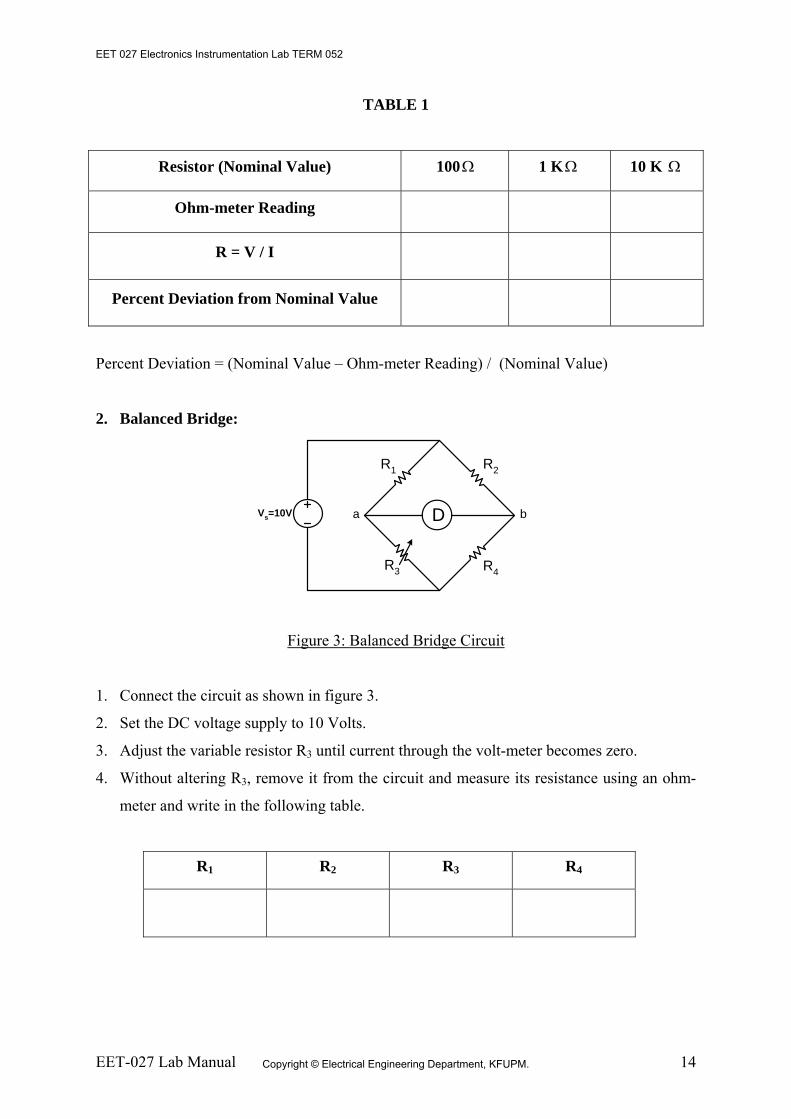
2. Balanced Bridge:
Vs=10V Da b
R1 R2
R4R3
Figure 3: Balanced Bridge Circuit
1. Connect the circuit as shown in figure 3.
2. Set the DC voltage supply to 10 Volts.
3. Adjust the variable resistor R3 until current through the volt-meter becomes zero.
4. Without altering R3, remove it from the circuit and measure its resistance using an ohm-
meter and write in the following table.
R1 R2 R3 R4
EET 027 Electronics Instrumentation Lab TERM 052
Copyright © Electrical Engineering Department, KFUPM.

EET-027 Lab Manual 15
Verification of Balanced Bridge Principle:
Conclusions:
R1 R4 R2 R3
EET 027 Electronics Instrumentation Lab TERM 052
Copyright © Electrical Engineering Department, KFUPM.

EET-027 Lab Manual 16
University Diploma Program Electronic Equipment Maintenance
Lab Instructor: Muhammad Ajmal Khan
EET-027, Experiment # 3 Wheatstone Bridge Circuit and Measurement of Resistance
using Wheatstone Bridge equipment
Objectives:
1. To experimentally study Wheatstone bridge. 2. To experimentally measure resistance using Wheatstone bridge equipment.
Apparatus:
DC Power Supply
DC current source
Few Resistors
Multimeter
Wheat bridge equipment
THEORY: Wheatstone Bridge Theory:
The Wheatstone Bridge is the most widely used circuit for precisely measuring resistance by
the comparison method. The bridge is named after Charles Wheatstone who invented it in
1843.
Wheatstone Bridge Equipment Description:
The Wheatstone Bridge is designed to be used for precision resistance measurements in the
laboratory. Values of resistance from 0.001 to 9,999,000 ohms can be measured with this
instrument. When the instrument is used as a Wheatstone bridge, the Ration Multiplier switch
allows selection of seven multipliers from 0.001 to 1,000. Multiplying the reading obtained
from the decade dials by the ratio selected yields the value, in ohms, of the unknown
resistance. Ratio resistances are accurate to ±0.05%. The zero-center, null-point-indicating
galvanometer has a sensitivity of 0.5 μA/div.
EET 027 Electronics Instrumentation Lab TERM 052
Copyright © Electrical Engineering Department, KFUPM.

EET-027 Lab Manual 17
PROCEDURE: 1. Simplified Wheatstone Bridge:
A simplified Wheatstone bridge circuit is shown in Figure 1. In the figure, R1, R2 and R3 are
precision, adjustable resistances and X is the unknown resistance. You are required to
measure the unknown resistance X.
Vs=10V Da b
R1 R2
XR3
Figure 1: Simplified Wheatstone Bridge Circuit
1. Connect the power supply and resistances as shown in figure 1.
2. Now vary resistances R3 until the volt-meter deflection is zero.
3. Now using the following formula, the unknown resistance X can be determined:
321 RRXR =
1
32
RRR
X =
R1 R2 R3 X
2. Measurement of Resistance using Wheatstone Bridge:
1. To measure the unknown resistance, set the Ratio Multiplier to “1.0” and set all decade
dials to “5”.
2. Tap the “Low” Galvanometer Sensitivity key and note the direction of the galvanometer
deflection.
3. When the direction of the galvanometer deflection is determined, change the Ratio
Multiplier one step at a time until the galvanometer deflection reverses direction.
EET 027 Electronics Instrumentation Lab TERM 052
Copyright © Electrical Engineering Department, KFUPM.

EET-027 Lab Manual 18
4. Vary the 1000-ohm decade dial to make the deflection a minimum. Continue to decrease
the deflection by varying the 100-ohm decade dial, the 10-ohm decade dial and finally the
1-ohm decade dial.
5. Depress the “High” Galvanometer Sensitivity key and, if necessary, further adjust the
decade dials for zero galvanometer deflection.
6. When the bridge is balanced the value of unknown resistance is equal to the product of
the Ratio Multiplier and the decade reading.
Resistor (Nominal Value) Ω 100 Ω1 K Ω10 K
Ohm-meter Reading
Wheatstone Bridge Reading
Conclustions:
EET 027 Electronics Instrumentation Lab TERM 052
Copyright © Electrical Engineering Department, KFUPM.

EET-027 Lab Manual 19
University Diploma Program Electronic Equipment Maintenance
Lab Instructor: Muhammad Ajmal Khan
EET-027, Experiment # 4
MATERIAL BEHAVIOR
Objectives:
1. To examine the behavior of thermister when heated.
2. To examine the behavior of nichrome wire when loaded with weight.
3. To examine the behavior of bimetallic strip when heated.
Apparatus: DC Power Supply
Wheatstone bridge
Multimeter
Thermisters
Bimetallic strip
THEORY: In this experiment, we will examine the behavior of some materials that affect control in
mechanisms. You should already know that most materials are affected by varying
environmental conditions. For instance, steel is affected by temperature, stress and strain. The
resistance and the length of copper is affected by temperature. The length of wood and hair
are affected by humidity. The conductivity of salt is affected by moisture. We use such
knowledge in the design of control equipment. This equipment will investigate the effects of
temperature, elongation, humidity, conductivity and hysteresis.
The resistance of a wire changes in two ways due to heat. One way is due to the temperature
only, and the other way is due to the deformation of the wire when heat is applied. The reason
that the resistance of a metal conductor changes when heat is applied is because the heat
agitates the electrons, creating movement of electrons, which influences the resistance.
EET 027 Electronics Instrumentation Lab TERM 052
Copyright © Electrical Engineering Department, KFUPM.

EET-027 Lab Manual 20
For most conducting materials, the resistance increases linearly with an increase in
temperature over normal temperature ranges. Some alloys have been developed which do not
increase very much at all with an increase in temperature. Temperature has very little effect
on the resistance of this type of material.
There are a few materials that have a negative temperature-resistance characteristic; that is,
the resistance decreases as the temperature increases. Carbon is one example. Some materials
with high temperature characteristics are used in temperature-measuring devices. These
materials often exhibit non-linear resistance characteristics and are known by names like
sensitors or thermisters. The resistance of wire also changes with change in length. The
change in length can be brought about through effects of temperature, or by stretching.
The coefficient of linear expansion is a term used when dealing with materials whose length
changes due to temperature changes, stretching due to strain, etc. The coefficient of linear
expansion, C, is defined as the change in length, of each unit length, for a rise of temperature
of one degree. The most common example of temperature affecting the length of an object is
the mercury tube thermometer. It is well known that a mercury tube thermometer is a good
indicator of temperature because of its linear expansion when influenced by small
temperature changes. When heated, the mercury column expands and rises, and when cooled,
the mercury column contracts and returns toward the bottom.
Another example of a control device utilizing expansion due to heat is the thermostat. The
temperature-sensitive part of the thermostat is a bimetallic strip consisting of two dissimilar
metals welded together. Each material has a different rate of expansion due to heat.
Commonly used materials are brass with a high rate of expansion, and invar, an alloy of
nickel and iron, which has a relatively low rate of expansion. As the bimetallic strip is heated,
the greater expansion rate of the brass will cause the free end of the strip to bend upward.
When cooled, the strip will return to its original position. The amount the strip bends is
directly proportional to the temperature.
The thermostat may be used as an indicating thermometer by attaching a pointer to the free
end of the strip and permitting it to move over a calibrated temperature scale. It may also be
used to activate the control circuit of some heating or cooling system. When the contacts
touch, a circuit is closed which in turn energizes the control mechanism.
EET 027 Electronics Instrumentation Lab TERM 052
Copyright © Electrical Engineering Department, KFUPM.

EET-027 Lab Manual 21
Another control device which utilizes the principle of temperature affecting the length of a
body is the heater thermostat used in the automobile. This device is shown in figure 1. When
the water temperature of the automobile is cold, the spring in figure 1 is in compression and
restricts the water flow path. Since the water circulation is restricted, it gets hotter and hotter
as the engine runs. When a preset temperature is reached, the spring begins to expand,
pushing the ballshaped plunger down out of its socket. As the plunger leaves the socket, the
water is able to flow more freely through the motor. This thermostat helps keep the engine at
a constant temperature, and helps in rapid warming of the heater during the winter months.
Figure 1: Automobile Thermostate
The length of a metallic conductor also changes when under stress. Here again the change in
length affects the resistance of the conductor. Because there are no absolutely elastic
materials, none will return to its exact original shape when the deforming force is removed.
This is because the molecular material has internal friciton. Steel, glass, copper, brass, and
other materials develop only small internal friction when they are only distorted a small
amount.
EET 027 Electronics Instrumentation Lab TERM 052
Copyright © Electrical Engineering Department, KFUPM.

EET-027 Lab Manual 22
PROCEDURE: A. Thermister:
1. Measure the resistance of the thermister using wheatstone bridge at room temperature.
2. Now start heating the thermister, then measure the resistance of thermister after heating.
3. Record the results below and then write your conclusions in your own words.
Thermister Resistance at Room Temperature: .
Thermister Resistance after Heating: .
Conclusions:
B. Bimetallic Strip:
1. You are provided a bimetallic strip.
2. Heat the bimetallic strip, you will observe the small deformation in its shape.
3. Write your conclusions in your own words.
Conclusions:
EET 027 Electronics Instrumentation Lab TERM 052
Copyright © Electrical Engineering Department, KFUPM.

EET-027 Lab Manual 23
University Diploma Program Electronic Equipment Maintenance
Lab Instructor: Muhammad Ajmal Khan
EET-027, Experiment # 5
Thermocouple Voltage Measurement
Objectives: To examine the thermocouple voltage and find corresponding temperature under the
following conditions:
1. To measure voltage of thermocouple without considering the intermediate
thermocouple effect of measurement setup.
2. To measure voltage of thermocouple with ice-point reference junction and fine
corresponding voltage using the thermocouple table.
3. To measure voltage of thermocouple using ambient reference block and calculate
the corrected voltage and then find the corresponding temperature.
Apparatus: J type thermocouples
4-1/2 digit DVM.
Temperature Indicator.
Ice point water
Boiling water
Theory:
Theory as per attached sheets.
EET 027 Electronics Instrumentation Lab TERM 052
Copyright © Electrical Engineering Department, KFUPM.

EET-027 Lab Manual 24
Procedure:
1. Setup the experiment as Figure 4 in theory sheets and measure voltage V.
V = _____________________
T = _____________________
2. Setup the experiment as Figure 6 of theory sheets and measure voltage V and
calculate V1. Find temperature (T1) corresponding to V1 from table.
)( 21
21
TTVVVV−=
−=α
where,
22
11
tVtVαα
==
15.273)()( 00 += KTCt
V V1 T T1
3. Setup the experiment according to figure 12.
a. Note reference temperature, which will be ambient temperature from
temperature indicator.
b. Measure V and find V1.
REFTVV α−= 1
c. Find the temperature from table corresponding to V.
TREF V V1 T T1
EET 027 Electronics Instrumentation Lab TERM 052
Copyright © Electrical Engineering Department, KFUPM.

EET-027 Lab Manual 25
4. Compare voltages from setup 1, 2 and 3 and write your conclusions below.
Conclusions: Explain:
Which set up gives the correct temperature?
Which set up gives maximum error?
EET 027 Electronics Instrumentation Lab TERM 052
Copyright © Electrical Engineering Department, KFUPM.

EET-027 Lab Manual 26
University Diploma Program Electronic Equipment Maintenance
Lab Instructor: Muhammad Ajmal Khan
EET-027, Experiment # 6
Strain Gauge Application and Measurement of Unknown Load
Objectives: 1. To find the effect of loading on strain gauge resistance using Wheatstone bridge.
2. To find the effect of loading on strain gauge and find voltage difference using bridge
circuit.
3. To find unknown load by using results and graphs obtained in part 1 and 2.
Apparatus: Strain gauge
Different Weights 1 kg, 2k, 5 kg.
4-1/2 digit DVM.
Wheatstone bridge
Three resistances of 120 ohms.
Power supply
Theory: The strain gauge is a transducer employing electrical resistance variation to sense the strain
produced by a force or weight. It is a very versatile detector for measuring weight, pressure,
mechanical force, or displacement.
Strain, being a fundamental engineering phenomenon, exists in all matters at all times, due
either to external loads or the weight of the matter itself. These strains vary in magnitude,
depending upon the materials and loads involved. Engineers have worked for centuries in an
attempt to measure strain accurately, but only in the last decade we have achieved much
advancement in the art of strain measurement. The terms linear deformation and strain are
synonymous and refer to the change in any linear dimension of a body, usually due to the
EET 027 Electronics Instrumentation Lab TERM 052
Copyright © Electrical Engineering Department, KFUPM.

EET-027 Lab Manual 27
application of external forces. The strain of a piece of rubber, when loaded, is ordinarily
apparent to the eye. However, the strain of a bridge strut as a locomotive passes may not be
apparent to the eye. Strain as defined above is often spoken of as "total strain." Average unit
strain is the amount of strain per unit length and has somewhat greater significance than does
total strain. Strain gauges are used to determine unit strain, and consequently when one refers
to strain, he is usually referring to unit strain. As defined, strain has units of inches per inch.
Strain gauges work on the principle that as a piece of wire is stretched, its resistance
changes. A strain gauge of either the bonded or the unbonded type is made of fine wire
wound back and forth in such a way that with a load applied to the material it is fastened to,
the strain gauge wire will stretch, increasing its length and decreasing its cross-sectional
area. The result will be an increase in its resistance, because the resistance, R, of a metallic
conductor varies directly with length, L, and inversely with cross-sectional area, A.
Mathematically the relationship is
ALR ρ=
where ρ is a constant depending upon the type of wire, L is the length of the wire in the
same units as ρ , and A is the cross-sectional area measured in units compatible with ρ .
Four properties of a strain gauge are important to consider when it is used to measure the
strain in a material. They are:
1. Gauge configuration.
2. Gauge sensitivity.
3. Gauge backing material.
4. Method of gauge attachment.
The sensitivity of a strain gauge is a function of the conductive material, size, configuration,
nominal resistance, and the way the gauge is energized.
Strain-gauge conductor materials may be either metal alloys or semiconductor material.
Nickel-chrome-iron-alloys tend to yield high gauge sensitivities as well as have long gauge
life. These alloys are quite good when used for dynamic strain measurements, but because of
a high temperature coefficient, they are not as satisfactory for static strain measurements.
EET 027 Electronics Instrumentation Lab TERM 052
Copyright © Electrical Engineering Department, KFUPM.

EET-027 Lab Manual 28
Copper-nickel alloys are generally use when temperatures are below 500 to 600°F. They are
less sensitive to temperature changes and provide a less sensitive gauge factor than the
nickel-chrome-iron alloys. Nickel-chrome alloys are useful in the construction of strain
gauges for high temperature measurements.
In using electric strain gauges, two physical qualities are of particular interest, the change in
gauge resistance and the change in length (strain). The relationship between these two
variables is dimensionless and is called the "gauge factor" of the strain gauge and can be
expressed mathematically as:
LL
RR
GFΔ
Δ=
StrainR
RGF
Δ=
In this relationship R and L represent, respectively, the initial resistance and the initial length
of the strain gauge wire, while ΔR and ΔL represent the small changes in resistance and
length which occur as the gauge is strained along with the surface to which it is bonded. The
gauge factor of a strain gauge is a measure of the amount of resistance change for a given
strain and is thus an index of the strain sensitivity of the gauge. With all other variables
remaining the same, the higher the gauge factor, the more sensitive the gauge and the greater
the electrical output.
The most common type of strain gauge used today for stress analysis is the bonded resistance
strain gauge shown below.
EET 027 Electronics Instrumentation Lab TERM 052
Copyright © Electrical Engineering Department, KFUPM.

EET-027 Lab Manual 29
These gauges use a grid of fine wire or a constantan metal foil grid encapsulated in a thin
resin backing. The gauge is glued to the carefully prepared test specimen by a thin layer of
epoxy. The epoxy acts as the carrier matrix to transfer the strain in the specimen to the strain
gauge. As the gauge changes in length, the tiny wires either contract or elongate depending
upon a tensile or compressive state of stress in the specimen. The cross-sectional area will
increase for compression and decrease in tension. Because the wire has an electrical
resistance that is proportional to the inverse of the cross-sectional area, A
R 1α , a measure of
the change in resistance will produce the strain in the material.
Procedure: (A) Using Wheatstone bridge:
1. Connect strain gauge with Wheatstone bridge and find the resistance of strain gauge
with no load and record the value in the table.
2. Find the resistance of strain gauge with loads, 1 kg, 2 kg, 3 kg, 4 kg and 5 kg, through
Wheatstone bridge and record the values in the table.
Load (kg) Resistance (ohms)
0
1
2
3
4
5
Unknown
3. Plot Resistance versus Load in the graph paper and write your conclusions.
EET 027 Electronics Instrumentation Lab TERM 052
Copyright © Electrical Engineering Department, KFUPM.

EET-027 Lab Manual 30
(B) Using Bridge Circuit: 1. Connect strain gauge with the bridge circuit as shown the following figure. Set the
power supply to 10 Volts and all three resistances are 120 ohms.
Vs=10V DVMa b
R1 R2
StrainGauge
R3
VΔ
2. Find the voltage difference ( VΔ ) across nodes “a” and “b” using digital volt-meter
(DVM) with no load and record the value in the table.
3. Find the voltage difference ( VΔ ) using digital volt-meter (DVM) with loads, 1 kg, 2
kg, 3 kg, 4 kg and 5 kg, and record the values in the following table.
Load (kg) VΔ Voltage Difference (mV)
0
1
2
3
4
5
Unknown
4. Plot the voltage difference VΔ versus Load in the graph paper and write your
conclusions.
EET 027 Electronics Instrumentation Lab TERM 052
Copyright © Electrical Engineering Department, KFUPM.

EET-027 Lab Manual 31
(C) Find Unknown Load using Graphs: 1. Find the unknown load using resistance versus load graph (obtained in part A).
Unknown Load : _____________________ kg.
2. Find the voltage difference using voltage difference versus load graph (obtained in part B).
Unknown Load : _____________________ kg.
Conclusions:
EET 027 Electronics Instrumentation Lab TERM 052
Copyright © Electrical Engineering Department, KFUPM.

EET-027 Lab Manual 32
University Diploma Program Electronic Equipment Maintenance
Lab Instructor: Muhammad Ajmal Khan
EET-027, Experiment # 7
Strain Gauge Measurement using Strain Indicator Objectives:
Find strain of the strain gauge using Strain Indicator.
Apparatus: Strain gauge
Different Weights 1 kg, 2k, 5 kg.
Strain Indicator
Theory: The strain gauge is a transducer employing electrical resistance variation to sense the strain
produced by a force or weight. It is a very versatile detector for measuring weight, pressure,
mechanical force, or displacement.
The Model P-3500 Strain Indicator is a portable, battery-powered instrument with unique
features for use in stress analysis testing, and for use with strain gage based transducers. In
use, the operator follows a logical sequence of setup steps by activating color-coded push-
button controls to prepare the instrument for making accurate and reliable measurements. The
P-3500 also incorporates a highly stable DC amplifier, precisely regulated bridge excitation
supply, and precisely settable gage factor controls.
Static measurements are displayed directly on the indicator's readout with 1 micro-strain
resolution. The instrument will accept full-, half-, or quarter-bridge strain gage inputs, and all
required bridge completion components for 120, 350 and 1000 ohm gages are built in.
Gage factor is precisely settable (to a resolution of 0.001) by a front-panel 10-turn
potentiometer, and is displayed on the digital readout when the gage factor push button is
depressed.
EET 027 Electronics Instrumentation Lab TERM 052
Copyright © Electrical Engineering Department, KFUPM.

EET-027 Lab Manual 33
Strain Indicator P-3500 Front Panel
Procedure: The P-3500 is designed for ease of operation, the push-button switches and front panel
controls are arranged such that the proper setup procedure generally follows a straightforward
left-to-right sequence. To measure the strain, the steps is outlined below:
1. Select 1/4-1 /2 position of BRIDGE push button.
2. Select Xl position of MULT push button.
3. Connect strain gage to binding posts connector. These binding posts are color-coded in
accordance with conventional practice, and are clearly labeled. Input connections are
shown on the inside cover of the instrument.
4. Depress AMP ZERO push button. Allow instrument to warm up for two minutes
minimum. Set AMP ZERO control for a readout display of ±0000. This adjustment must
be made with MULT in Xl position.
5. Depress GAGE FACTOR push button. Set GAGE FACTOR range switch and GAGE
FACTOR control for the desired gage factor.
6. Depress the RUN push button. Set the BALANCE switch and the BALANCE control for
a reading of ±0000. This setting must be made with the MULT in the Xl position.
7. Depress the CAL push button and verify calibration of the instrument.
8. Select the Xl or Xl 0 MUL T position as required.
9. Depress the RUN push button. Load the strain gage system using and record the reading
in the table 1.
EET 027 Electronics Instrumentation Lab TERM 052
Copyright © Electrical Engineering Department, KFUPM.

EET-027 Lab Manual 34
Table 1
Load (kg) Strain (micro-strain)
0
1
2
3
4
5
Unknown
Find Unknown Load using Graph: 1. Plot the readings obtained from tables 1 on the graph paper as strain versus load.
2. Find the unknown load using strain versus load graph (obtained from table 1).
Unknown Load : _____________________ kg.
Conclusions:
EET 027 Electronics Instrumentation Lab TERM 052
Copyright © Electrical Engineering Department, KFUPM.

EET-027 Lab Manual 35
University Diploma Program Electronic Equipment Maintenance
Lab Instructor: Muhammad Ajmal Khan
EET-027, Experiment # 8
Strain Gauge Measurement by Applying Displacement using Strain Indicator
Objectives: Measuring strain when the strip end is displaced in the strain gauge micrometer device.
Apparatus: Strain gauge
Staring gauge micrometer
Different Weights 1 kg, 2k, 5 kg.
Strain Indicator
Theory:
The strain gauge is a transducer employing electrical resistance variation to sense the strain
produced by a force or weight. It is a very versatile detector for measuring weight, pressure,
mechanical force, or displacement.
The Model P-3500 Strain Indicator is a portable, battery-powered instrument with unique
features for use in stress analysis testing, and for use with strain gage based transducers. In
use, the operator follows a logical sequence of setup steps by activating color-coded push-
button controls to prepare the instrument for making accurate and reliable measurements. The
P-3500 also incorporates a highly stable DC amplifier, precisely regulated bridge excitation
supply, and precisely settable gage factor controls.
Static measurements are displayed directly on the indicator's readout with 1 micro-strain
resolution. The instrument will accept full-, half-, or quarter-bridge strain gage inputs, and all
required bridge completion components for 120, 350 and 1000 ohm gages are built in.
EET 027 Electronics Instrumentation Lab TERM 052
Copyright © Electrical Engineering Department, KFUPM.

EET-027 Lab Manual 36
Gage factor is precisely settable (to a resolution of 0.001) by a front-panel 10-turn
potentiometer, and is displayed on the digital readout when the gage factor push button is
depressed.
Strain Indicator P-3500 Front Panel
Procedure: 1. Measuring Strain using Strain Indicator: The P-3500 is designed for ease of operation, the push-button switches and front panel
controls are arranged such that the proper setup procedure generally follows a straightforward
left-to-right sequence. To measure the strain, the steps is outlined below:
1. Select 1/4-1 /2 position of BRIDGE push button.
2. Select Xl position of MULT push button.
3. Connect strain gage to binding posts connector. These binding posts are color-coded in
accordance with conventional practice, and are clearly labeled. Input connections are
shown on the inside cover of the instrument.
4. Depress AMP ZERO push button. Allow instrument to warm up for two minutes
minimum. Set AMP ZERO control for a readout display of ±0000. This adjustment must
be made with MULT in Xl position.
5. Depress GAGE FACTOR push button. Set GAGE FACTOR range switch and GAGE
FACTOR control for the desired gage factor.
6. Depress the RUN push button. Set the BALANCE switch and the BALANCE control for
a reading of ±0000. This setting must be made with the MULT in the Xl position.
EET 027 Electronics Instrumentation Lab TERM 052
Copyright © Electrical Engineering Department, KFUPM.

EET-027 Lab Manual 37
7. Depress the CAL push button and verify calibration of the instrument.
8. Select the Xl or Xl 0 MUL T position as required.
9. Depress the RUN push button. Displace the end of strip and record the reading of strain in
the table 1.
10. Plot the graph of Strain versus Resultant Displacement and find the slope of the graph and
find strain at displacement of 0.115 inch from graph.
Table 1
S. No. Displacement (inch)
Resultant Displacement (x-a)
(inch)
Strain (micro-strain)
1 a = 0
2
3
4
5
6
7
8
9
10
11
12
13
EET 027 Electronics Instrumentation Lab TERM 052
Copyright © Electrical Engineering Department, KFUPM.

EET-027 Lab Manual 38
2. Measuring Differential Voltage of Full Bridge Circuit when Strip is displaced:
1. Connect strain gauge with the bridge circuit as shown the following figure. Set the power
supply to 10 Volts and all three resistances are 120 ohms.
Vs=10V DVMa b
R1 R2
StrainGauge
R3
VΔ
2. Find the voltage difference ( VΔ ) across nodes “a” and “b” using digital volt-meter
(DVM) without any displacement and record the value in the table 2.
3. Apply some displacement using micrometer and find the voltage difference ( VΔ ) using
digital volt-meter (DVM) and record the values in the following table 2.
4. Plot the graph of differential voltage versus Resultant Displacement and find the slope of
the graph and find the differential voltage at displacement of 0.115 inch from graph.
Table 1
S. No. Displacement (inch)
Resultant Displacement (x-a) (inch)
Differential Voltage (Volts)
1 a = 0
2
3
4
5
6
7
8
EET 027 Electronics Instrumentation Lab TERM 052
Copyright © Electrical Engineering Department, KFUPM.

EET-027 Lab Manual 39
9
10
Conclusions: Compare the slope of the two graphs? And write your comments.
EET 027 Electronics Instrumentation Lab TERM 052
Copyright © Electrical Engineering Department, KFUPM.

EET-027 Lab Manual 40
University Diploma Program Electronic Equipment Maintenance
Lab Instructor: Muhammad Ajmal Khan
EET-027, Experiment # 9
Linear Variable Differential Transformer Measurements
Objectives: Measuring voltage with displacement variation using Linear Variable Differential
Transformer (LVDT).
Apparatus: LVDT
Micrometer for LVDT
Voltmeter
Theory:
The Linear Variable Differential Transformer is a position sensing device that provides an
AC output voltage proportional to the displacement of its core passing through its windings.
LVDTs provide linear output for small displacements where the core remains within the
primary coils. The exact distance is a function of the geometry of the LVDT.
An LVDT is much like any other transformer in that it consists of a primary coil, secondary
coils, and a magnetic core. An alternating current, known as the carrier signal, is produced in
the primary coil. The changing current in the primary coil produces a varying magnetic field
around the core. This magnetic field induces an alternating (AC) voltage in the secondary
coils that are in proximity to the core. As with any transformer, the voltage of the induced
EET 027 Electronics Instrumentation Lab TERM 052
Copyright © Electrical Engineering Department, KFUPM.

EET-027 Lab Manual 41
signal in the secondary coil is linearly related to the number of coils. The basic transformer
relation is:
where:
Vout is the voltage at the output,
Vin is the voltage at the input,
Nout is the number of windings of the output coil, and
Nin is the number of windings of the input coil.
As the core is displaced, the number of coils in the secondary coil exposed to the coil changes
linearly. Therefore the amplitude of the induced signal varies linearly with displacement.
The LVDT indicates direction of displacement by having the two secondary coils whose
outputs are balanced against one another. The secondary coils in an LVDT are connected in
the opposite sense (one clockwise, the other counter clockwise). Thus when the same varying
magnetic field is applied to both secondary coils, their output voltages have the same
amplitude but differ in sign. The outputs from the two secondary coils are summed together,
usually by simply connecting the secondary coils together at a common center point. At an
equilibrium position (generally zero displacement) a zero output signal is produced.
The induced AC signal is then demodulated so that a DC voltage that is sensitive to the
amplitude and phase of the AC signal is produced.
EET 027 Electronics Instrumentation Lab TERM 052
Copyright © Electrical Engineering Department, KFUPM.

EET-027 Lab Manual 42
Procedure: 1. Connect the LVDT with the micrometer.
2. Connect the Voltmeter with the LVDT signal conditioner.
3. Connect the LVDT signal conditioner with the power supply of 110 Volts.
4. Set the position of LVDT such that a range of voltage from +10 to -10 volts can be
achieved.
5. Change the LVDT displacement and record the voltmeter reading in the table.
6. Plot the graph voltage versus displacement.
Table 1
S. No. Displacement (inch)
Resultant Displacement (x-a) (inch)
Voltage (Volts)
1 a =
2
3
4
5
6
7
8
9
10
11
12
13
EET 027 Electronics Instrumentation Lab TERM 052
Copyright © Electrical Engineering Department, KFUPM.

EET-027 Lab Manual 43
Conclusions:
EET 027 Electronics Instrumentation Lab TERM 052
Copyright © Electrical Engineering Department, KFUPM.

EET-027 Lab Manual 44
University Diploma Program Electronic Equipment Maintenance
Lab Instructor: Muhammad Ajmal Khan
EET-027, Experiment # 10
Event Counting using Slotted Opto Switch
Objectives: Design a circuit to count rotations of a disk/wheel using slotted opto switch.
Apparatus: Slotted opto switch RS 306-061
Transistor, 2N3053
Resistors, 270 ohms, 22 k-ohms, 4.7 k-ohms.
Theory: Slotted type Opto Switches are used when an object is located in the sensing position in the
slot between the emitter and the receiver, it intercepts the optical beam of the emitter.
Procedure: 1. Connect the circuit as shown in the figure.
EET 027 Electronics Instrumentation Lab TERM 052
Copyright © Electrical Engineering Department, KFUPM.

EET-027 Lab Manual 45
2. First connect the LED at the counting terminal of the circuit.
3. Set the wheel (attached with the DC motor) in between the slots of the opto switch.
4. Turn ON the power supply and turn ON the DC motor and observe that the LED will
be blinking because of the wheel rotations, that shows the low and high pulse across
the LED.
5. Connect the oscilloscope instead of the LED and observe the pulse in the
oscilloscope.
6. Connect the counter instead of the LED and observe the counting of the wheel
rotations.
Conclusions:
EET 027 Electronics Instrumentation Lab TERM 052
Copyright © Electrical Engineering Department, KFUPM.

EET-027 Lab Manual 46
University Diploma Program Electronic Equipment Maintenance
Lab Instructor: Muhammad Ajmal Khan
EET-027, Experiment # 11
X-Y Recorder
Objectives: Record both strain gauge resistance variation and LVDT displacement variation
simultaneously on the XY Recorder.
Apparatus: LVDT
Strain Gauge
Strain Gauge Indicator
LVDT conditioner
XY Recorder
Theory: We use an analog recorder so the operator can see what is happening while the experiment is
in progress. An X-Y recorder is used for recording two signals simultaneously. Here the
system consists of a strain transducer which produces a signal proportional to the applied
load, an LVDT which produces a signal proportional to the vertical displacement of the
sample, and an X-Y recorder for recording both signals simultaneously.
The X-Y recorder is a very useful instrument for measuring and plotting various voltage
signals. A one-pen recorder for instance can plot two signals simultaneously, one as a
function of the other, or one signal as a function of time. There are multi-pen recorders that
can plot many signals simultaneously. Although the X-Y recorder is a voltage measuring
device, the voltage can represent most anything, depending upon the problem. When using
the X-Y recorder to record. For example, an X-Y recorder rated at a slew-rate of 40
cm/second would give an inaccurate recording for signals exceeding this rating. In using the
X-Y recorder, it is obviously important that one know how to “set it up”. Normally, this is not
EET 027 Electronics Instrumentation Lab TERM 052
Copyright © Electrical Engineering Department, KFUPM.

EET-027 Lab Manual 47
difficult if the magnitudes of the signals being recorded are such that the calibrated settings
on the X-Y recorder can be used.
Procedure: 1. Set up the connection as quarter bridge on strain indicator.
2. Connect the analog output of the strain indicator with the X side of the X-Y recorder.
3. Set the LVDT with stand to monitor the displacement and connect it to LVDT
conditioner.
4. Connect output of LVDT conditioner to the Y axis of recorder of recorder.
5. Set the X-Y recorder range and scales; X scale in mV range and Y in Voltage range.
6. Put some load on the strip and observe the plot in the X-Y recorder.
7. Put load of 500 gm, 1 kg, 1.5 kg, 2 kg, 2.5 kg and observe the plot in the X-Y
recorder.
Conclusions:
EET 027 Electronics Instrumentation Lab TERM 052
Copyright © Electrical Engineering Department, KFUPM.

EET-027 Lab Manual 48
University Diploma Program Electronic Equipment Maintenance
Lab Instructor: Muhammad Ajmal Khan
EET-027, Experiment # 12
PC-Based Data Logging
Objectives: Designing of PC-Based Data Logging and Recording system for the temperature.
Apparatus: A Computer with windows operating system, Matlab, and Terminal Software.
A Temperature sensor device with serial port interface feature
Theory: Data logging and recording is a very common measurement application. In its most basic
form, data logging is the measurement and recording of physical or electrical parameters over
a period of time. The data can be temperature, strain, displacement, flow, pressure, voltage,
current, resistance, power, or any of a wide range of other parameters. Real-world data
logging applications are typically more involved than just acquiring and recording signals,
typically involving some combination of online analysis, offline analysis, display, report
generation, and data sharing. Moreover, many data logging applications are beginning to
require the acquisition and storage of other types of data, such as recording sound and video
in conjunction with the other parameters measured during an automobile crash test.
Data logging is used in a broad spectrum of applications. Chemists record data such as
temperature, pH, and pressure when performing experiments in a lab. Design engineers log
performance parameters such as vibration, temperature, and battery level to evaluate product
designs. Civil engineers record strain and load on bridges over time to evaluate safety.
Geologists use data logging to determine mineral formations when drilling for oil. Breweries
log the conditions of their storage and brewing facilities to maintain quality. (See attached
tutorials A Review of PC-Based Data Logging and Recording Techniques for more detail).
EET 027 Electronics Instrumentation Lab TERM 052
Copyright © Electrical Engineering Department, KFUPM.

EET-027 Lab Manual 49
The list of applications for data logging goes on and on, but all of these applications have
similar common requirements. The purpose of this experiment is to design a simple data
logging system to record the data from a temperature sensor and analyze the data in real
environment.
Realterm is a terminal program specially designed for capturing, controlling and debugging
binary and other difficult data streams. It is far better for debugging comms than
Hyperterminal. It has no support for dialing modems, BBS etc - that is what hyperterminal
does. (See attached tutorial of Terminal Software for more details)
Procedure:
1. Connect the temperature sensor device with the computer through serial port
interface.
2. Start the Real Term software in the computer.
3. Configure settings of Real Term software, go to Port option and set baud rate to 9600
bps, then go to Capture option and set the path and filename to save the captured data.
4. Start Matlab and run the program exp13.m
5. Observe the graph representing temperature versus time.
Conclusion:
EET 027 Electronics Instrumentation Lab TERM 052
Copyright © Electrical Engineering Department, KFUPM.