Embed Size (px)
Citation preview
Instrument Messages and Functional Tests
Agilent Technologies
PSA Series Spectrum Analyzers
and
ESA Series Spectrum Analyzers
Manufacturing Part Number: E4440-90246Supersedes: E4440-90228
Printed in USA
April 2004
© Copyright 2001-2004 Agilent Technologies, Inc.
NoticeThe information contained in this document is subject to change without notice.
Agilent Technologies makes no warranty of any kind with regard to this material, including but not limited to, the implied warranties of merchantability and fitness for a particular purpose. Agilent Technologies shall not be liable for errors contained herein or for incidental or consequential damages in connection with the furnishing, performance, or use of this material.
Where to Find the Latest InformationDocumentation is updated periodically. For the latest information about Agilent PSA or ESA spectrum analyzers, including firmware upgrades and application information, please visit the following Internet URLs:
http://www.agilent.com/find/esa
http://www.agilent.com/find/psa
2
ContentsTab
le of C
on
tents
1. Instrument MessagesInstrument Messages Introduction . . . . . . . . . . . . . . . . . . . . . . . . . . . . . . . . . . . . . . . . . . . . . 30
Error Queues . . . . . . . . . . . . . . . . . . . . . . . . . . . . . . . . . . . . . . . . . . . . . . . . . . . . . . . . . . . . . 31Error Message Format . . . . . . . . . . . . . . . . . . . . . . . . . . . . . . . . . . . . . . . . . . . . . . . . . . . . . . 32Error Message Types . . . . . . . . . . . . . . . . . . . . . . . . . . . . . . . . . . . . . . . . . . . . . . . . . . . . . . . 33
Instrument Messages . . . . . . . . . . . . . . . . . . . . . . . . . . . . . . . . . . . . . . . . . . . . . . . . . . . . . . . . 34Error Messages . . . . . . . . . . . . . . . . . . . . . . . . . . . . . . . . . . . . . . . . . . . . . . . . . . . . . . . . . . . . 34Instrument Messages Without Numbers . . . . . . . . . . . . . . . . . . . . . . . . . . . . . . . . . . . . . . . 81
2. Functional TestsWhat You Will Find in This Chapter . . . . . . . . . . . . . . . . . . . . . . . . . . . . . . . . . . . . . . . . . . . . 96
What Are the Functional Tests? . . . . . . . . . . . . . . . . . . . . . . . . . . . . . . . . . . . . . . . . . . . . . . 96Functional Test Versus Performance Verification . . . . . . . . . . . . . . . . . . . . . . . . . . . . . . . . 96This chapter includes the following: . . . . . . . . . . . . . . . . . . . . . . . . . . . . . . . . . . . . . . . . . . . 96Before Performing a Functional Test . . . . . . . . . . . . . . . . . . . . . . . . . . . . . . . . . . . . . . . . . . 97
Test Equipment . . . . . . . . . . . . . . . . . . . . . . . . . . . . . . . . . . . . . . . . . . . . . . . . . . . . . . . . . . . . . 98
3. PSA Functional TestsAmplitude Accuracy at 50 MHz . . . . . . . . . . . . . . . . . . . . . . . . . . . . . . . . . . . . . . . . . . . . . . . 102
Test Limits . . . . . . . . . . . . . . . . . . . . . . . . . . . . . . . . . . . . . . . . . . . . . . . . . . . . . . . . . . . . . . 102Test Description . . . . . . . . . . . . . . . . . . . . . . . . . . . . . . . . . . . . . . . . . . . . . . . . . . . . . . . . . . 102Procedure . . . . . . . . . . . . . . . . . . . . . . . . . . . . . . . . . . . . . . . . . . . . . . . . . . . . . . . . . . . . . . . 103Testing Option 1DS (Preamp) . . . . . . . . . . . . . . . . . . . . . . . . . . . . . . . . . . . . . . . . . . . . . . . 106
Displayed Average Noise Level (DANL) . . . . . . . . . . . . . . . . . . . . . . . . . . . . . . . . . . . . . . . . 107Test Limits (with 0 dB input attenuation) . . . . . . . . . . . . . . . . . . . . . . . . . . . . . . . . . . . . . 107Test Description . . . . . . . . . . . . . . . . . . . . . . . . . . . . . . . . . . . . . . . . . . . . . . . . . . . . . . . . . . 107Procedure . . . . . . . . . . . . . . . . . . . . . . . . . . . . . . . . . . . . . . . . . . . . . . . . . . . . . . . . . . . . . . . 107
Frequency Readout Accuracy . . . . . . . . . . . . . . . . . . . . . . . . . . . . . . . . . . . . . . . . . . . . . . . . . 109Test Limits . . . . . . . . . . . . . . . . . . . . . . . . . . . . . . . . . . . . . . . . . . . . . . . . . . . . . . . . . . . . . . 109Test Description . . . . . . . . . . . . . . . . . . . . . . . . . . . . . . . . . . . . . . . . . . . . . . . . . . . . . . . . . . 109Procedure . . . . . . . . . . . . . . . . . . . . . . . . . . . . . . . . . . . . . . . . . . . . . . . . . . . . . . . . . . . . . . . 110
Frequency Response (Flatness) . . . . . . . . . . . . . . . . . . . . . . . . . . . . . . . . . . . . . . . . . . . . . . . 111Test Limits . . . . . . . . . . . . . . . . . . . . . . . . . . . . . . . . . . . . . . . . . . . . . . . . . . . . . . . . . . . . . . 111Test Description . . . . . . . . . . . . . . . . . . . . . . . . . . . . . . . . . . . . . . . . . . . . . . . . . . . . . . . . . . 111Procedure . . . . . . . . . . . . . . . . . . . . . . . . . . . . . . . . . . . . . . . . . . . . . . . . . . . . . . . . . . . . . . . 112
Amplitude Linearity . . . . . . . . . . . . . . . . . . . . . . . . . . . . . . . . . . . . . . . . . . . . . . . . . . . . . . . . 115Test Limits . . . . . . . . . . . . . . . . . . . . . . . . . . . . . . . . . . . . . . . . . . . . . . . . . . . . . . . . . . . . . . 115Test Description . . . . . . . . . . . . . . . . . . . . . . . . . . . . . . . . . . . . . . . . . . . . . . . . . . . . . . . . . . 115Procedure . . . . . . . . . . . . . . . . . . . . . . . . . . . . . . . . . . . . . . . . . . . . . . . . . . . . . . . . . . . . . . . 116
Second Harmonic Distortion (SHD) . . . . . . . . . . . . . . . . . . . . . . . . . . . . . . . . . . . . . . . . . . . . 118Test Limits . . . . . . . . . . . . . . . . . . . . . . . . . . . . . . . . . . . . . . . . . . . . . . . . . . . . . . . . . . . . . . 118Test Description . . . . . . . . . . . . . . . . . . . . . . . . . . . . . . . . . . . . . . . . . . . . . . . . . . . . . . . . . . 118Procedure . . . . . . . . . . . . . . . . . . . . . . . . . . . . . . . . . . . . . . . . . . . . . . . . . . . . . . . . . . . . . . . 119
4. ESA Functional TestsDisplayed Average Noise Level . . . . . . . . . . . . . . . . . . . . . . . . . . . . . . . . . . . . . . . . . . . . . . . 122
Test Limits . . . . . . . . . . . . . . . . . . . . . . . . . . . . . . . . . . . . . . . . . . . . . . . . . . . . . . . . . . . . . . 122Test Description . . . . . . . . . . . . . . . . . . . . . . . . . . . . . . . . . . . . . . . . . . . . . . . . . . . . . . . . . . 123
3

ContentsTa
ble
of
Co
nte
nts
Procedure (10 MHz to 500 MHz) E4401B and E4411B . . . . . . . . . . . . . . . . . . . . . . . . . . . .124Procedure (501 MHz to 1.0 GHz) E4401B and E4411B . . . . . . . . . . . . . . . . . . . . . . . . . . .125Procedure (1.01 GHz to 1.5 GHz) E4401B and E4411B . . . . . . . . . . . . . . . . . . . . . . . . . . .126Procedure (10 MHz to 1 GHz) E4402B, E4403B, E4404B, E4405B, E4407B, and E4408B . .127Procedure (1.01 GHz to 2 GHz) E4402B, E4403B, E4404B, E4405B, E4407B, and E4408B .128Procedure (2.01 GHz to 3.0 GHz) E4402B, E4403B, E4404B, E4405B, E4407B, and E4408B 129Procedure (3.01 GHz to 6.0 GHz) E4404B, E4405B, E4407B, and E4408B . . . . . . . . . . . .131Procedure (6.01 GHz to 6.7 GHz) E4404B . . . . . . . . . . . . . . . . . . . . . . . . . . . . . . . . . . . . . .132Procedure (6.01 GHz to 12.0 GHz) E4405B, E4407B, and E4408B . . . . . . . . . . . . . . . . . .133Procedure (12.01 GHz to 13.2 GHz) E4405B . . . . . . . . . . . . . . . . . . . . . . . . . . . . . . . . . . . .134Procedure (12.01 GHz to 22 GHz) E4407B and E4408B . . . . . . . . . . . . . . . . . . . . . . . . . . .135Procedure (22.01 GHz to 26.5 GHz) E4407B and E4408B . . . . . . . . . . . . . . . . . . . . . . . . .136
Frequency Readout Accuracy . . . . . . . . . . . . . . . . . . . . . . . . . . . . . . . . . . . . . . . . . . . . . . . . . .139Test Limits . . . . . . . . . . . . . . . . . . . . . . . . . . . . . . . . . . . . . . . . . . . . . . . . . . . . . . . . . . . . . . .139Test Description . . . . . . . . . . . . . . . . . . . . . . . . . . . . . . . . . . . . . . . . . . . . . . . . . . . . . . . . . . .139Procedure . . . . . . . . . . . . . . . . . . . . . . . . . . . . . . . . . . . . . . . . . . . . . . . . . . . . . . . . . . . . . . . .140
Marker Count Accuracy . . . . . . . . . . . . . . . . . . . . . . . . . . . . . . . . . . . . . . . . . . . . . . . . . . . . . .141Procedure . . . . . . . . . . . . . . . . . . . . . . . . . . . . . . . . . . . . . . . . . . . . . . . . . . . . . . . . . . . . . . . .141
Frequency Response (Flatness) . . . . . . . . . . . . . . . . . . . . . . . . . . . . . . . . . . . . . . . . . . . . . . . .142Test Limits . . . . . . . . . . . . . . . . . . . . . . . . . . . . . . . . . . . . . . . . . . . . . . . . . . . . . . . . . . . . . . .142Test Description . . . . . . . . . . . . . . . . . . . . . . . . . . . . . . . . . . . . . . . . . . . . . . . . . . . . . . . . . . .142Procedure . . . . . . . . . . . . . . . . . . . . . . . . . . . . . . . . . . . . . . . . . . . . . . . . . . . . . . . . . . . . . . . .143
Reference Level Accuracy . . . . . . . . . . . . . . . . . . . . . . . . . . . . . . . . . . . . . . . . . . . . . . . . . . . . .146Test Limits . . . . . . . . . . . . . . . . . . . . . . . . . . . . . . . . . . . . . . . . . . . . . . . . . . . . . . . . . . . . . . .146Test Description . . . . . . . . . . . . . . . . . . . . . . . . . . . . . . . . . . . . . . . . . . . . . . . . . . . . . . . . . . .146Log Mode Procedure . . . . . . . . . . . . . . . . . . . . . . . . . . . . . . . . . . . . . . . . . . . . . . . . . . . . . . .147Linear Mode Procedure . . . . . . . . . . . . . . . . . . . . . . . . . . . . . . . . . . . . . . . . . . . . . . . . . . . . .149
Resolution Bandwidth Switching Uncertainty . . . . . . . . . . . . . . . . . . . . . . . . . . . . . . . . . . . .151Test Limits . . . . . . . . . . . . . . . . . . . . . . . . . . . . . . . . . . . . . . . . . . . . . . . . . . . . . . . . . . . . . . .151Test Description . . . . . . . . . . . . . . . . . . . . . . . . . . . . . . . . . . . . . . . . . . . . . . . . . . . . . . . . . . .151Procedure . . . . . . . . . . . . . . . . . . . . . . . . . . . . . . . . . . . . . . . . . . . . . . . . . . . . . . . . . . . . . . . .152
Scale Fidelity . . . . . . . . . . . . . . . . . . . . . . . . . . . . . . . . . . . . . . . . . . . . . . . . . . . . . . . . . . . . . .154Test Limits . . . . . . . . . . . . . . . . . . . . . . . . . . . . . . . . . . . . . . . . . . . . . . . . . . . . . . . . . . . . . . .154Test Description . . . . . . . . . . . . . . . . . . . . . . . . . . . . . . . . . . . . . . . . . . . . . . . . . . . . . . . . . . .154Procedure . . . . . . . . . . . . . . . . . . . . . . . . . . . . . . . . . . . . . . . . . . . . . . . . . . . . . . . . . . . . . . . .155
Second Harmonic Spurious Responses . . . . . . . . . . . . . . . . . . . . . . . . . . . . . . . . . . . . . . . . . .157Test Limits . . . . . . . . . . . . . . . . . . . . . . . . . . . . . . . . . . . . . . . . . . . . . . . . . . . . . . . . . . . . . . .157Test Description . . . . . . . . . . . . . . . . . . . . . . . . . . . . . . . . . . . . . . . . . . . . . . . . . . . . . . . . . . .157Procedure . . . . . . . . . . . . . . . . . . . . . . . . . . . . . . . . . . . . . . . . . . . . . . . . . . . . . . . . . . . . . . . .158
Tracking Generator Level Flatness: Models E4401B and E4411B, Options 1DN and 1DQ 160 Test Limits . . . . . . . . . . . . . . . . . . . . . . . . . . . . . . . . . . . . . . . . . . . . . . . . . . . . . . . . . . . . . .160Test Description . . . . . . . . . . . . . . . . . . . . . . . . . . . . . . . . . . . . . . . . . . . . . . . . . . . . . . . . . . .160Procedure . . . . . . . . . . . . . . . . . . . . . . . . . . . . . . . . . . . . . . . . . . . . . . . . . . . . . . . . . . . . . . . .161
Tracking Generator Level Flatness: E4402B, E4403B, E4404B, E4405B, E4407B and E4408B, Option 1DN . . . . . . . . . . . . . . .163
Test Limits . . . . . . . . . . . . . . . . . . . . . . . . . . . . . . . . . . . . . . . . . . . . . . . . . . . . . . . . . . . . . . .163
4

ContentsTab
le of C
on
tents
Test Description . . . . . . . . . . . . . . . . . . . . . . . . . . . . . . . . . . . . . . . . . . . . . . . . . . . . . . . . . . 163Procedure . . . . . . . . . . . . . . . . . . . . . . . . . . . . . . . . . . . . . . . . . . . . . . . . . . . . . . . . . . . . . . . 164
5

ContentsTa
ble
of
Co
nte
nts
6
Instrument MessagesAlphabetical Listing
Instru
men
t Messag
es
(ADC Align Failure) . . . . . . . . . . . . . . . . . . . . . . . . . . . . . . . . . . . . . . . . . . . . . . . . . . . . . . . . . . . . . . . 87
(FM Demod Align Failure) . . . . . . . . . . . . . . . . . . . . . . . . . . . . . . . . . . . . . . . . . . . . . . . . . . . . . . . . . . 88
(IF Align Failure) . . . . . . . . . . . . . . . . . . . . . . . . . . . . . . . . . . . . . . . . . . . . . . . . . . . . . . . . . . . . . . . . . 89
(IF/ADC Over Range) . . . . . . . . . . . . . . . . . . . . . . . . . . . . . . . . . . . . . . . . . . . . . . . . . . . . . . . . . . . . . . 89
(LO Align Failure) status bit only, no message . . . . . . . . . . . . . . . . . . . . . . . . . . . . . . . . . . . . . . . . . . 89
(RF Align Failure) . . . . . . . . . . . . . . . . . . . . . . . . . . . . . . . . . . . . . . . . . . . . . . . . . . . . . . . . . . . . . . . . . 91
(TG Align Failure) status bit only, no message . . . . . . . . . . . . . . . . . . . . . . . . . . . . . . . . . . . . . . . . . . 92
* (Invalid Data) . . . . . . . . . . . . . . . . . . . . . . . . . . . . . . . . . . . . . . . . . . . . . . . . . . . . . . . . . . . . . . . . . . . 86
*CLS . . . . . . . . . . . . . . . . . . . . . . . . . . . . . . . . . . . . . . . . . . . . . . . . . . . . . . . . . . . . . . . . . . . . . . . . . . . 31
*CLS . . . . . . . . . . . . . . . . . . . . . . . . . . . . . . . . . . . . . . . . . . . . . . . . . . . . . . . . . . . . . . . . . . . . . . . . . . . 34
<directoryname> directory deleted . . . . . . . . . . . . . . . . . . . . . . . . . . . . . . . . . . . . . . . . . . . . . . . . . . . 82
<directoryname> directory deleted . . . . . . . . . . . . . . . . . . . . . . . . . . . . . . . . . . . . . . . . . . . . . . . . . . . 82
<filename> file copied. . . . . . . . . . . . . . . . . . . . . . . . . . . . . . . . . . . . . . . . . . . . . . . . . . . . . . . . . . . . . . 82
<filename> file deleted . . . . . . . . . . . . . . . . . . . . . . . . . . . . . . . . . . . . . . . . . . . . . . . . . . . . . . . . . . . . . 82
<filename> file loaded . . . . . . . . . . . . . . . . . . . . . . . . . . . . . . . . . . . . . . . . . . . . . . . . . . . . . . . . . . . . . 82
<filename> file saved . . . . . . . . . . . . . . . . . . . . . . . . . . . . . . . . . . . . . . . . . . . . . . . . . . . . . . . . . . . . . . 82
<filename> too many data entries . . . . . . . . . . . . . . . . . . . . . . . . . . . . . . . . . . . . . . . . . . . . . . . . . . . . 82
<name1> <directoryname1> directory renamed to <name2> . . . . . . . . . . . . . . . . . . . . . . . . . . . . . . 82
<name1> <filename1> file renamed to <name2> . . . . . . . . . . . . . . . . . . . . . . . . . . . . . . . . . . . . . . . . 83
’10101010’ pattern not detected - results may be inaccurate. . . . . . . . . . . . . . . . . . . . . . . . . . . . . . . 64
100 spurs found. Additional spurs ignored . . . . . . . . . . . . . . . . . . . . . . . . . . . . . . . . . . . . . . . . . . . . . 69
1st LO Unlock; Failure acquiring FracN LO frequency lock . . . . . . . . . . . . . . . . . . . . . . . . . . . . . . . 41
1st LO Unlock; Failure acquiring single loop FracN LO lock. . . . . . . . . . . . . . . . . . . . . . . . . . . . . . . 41
2nd LO Unlock . . . . . . . . . . . . . . . . . . . . . . . . . . . . . . . . . . . . . . . . . . . . . . . . . . . . . . . . . . . . . . . . . . . 41
3 − 26.5 GHz preselector bypassed, can’t adjust . . . . . . . . . . . . . . . . . . . . . . . . . . . . . . . . . . . . . . . . . 44
4th LO Unlock. . . . . . . . . . . . . . . . . . . . . . . . . . . . . . . . . . . . . . . . . . . . . . . . . . . . . . . . . . . . . . . . . . . . 41
50 MHz Osc Unlevel (50 MHz Osc Unleveled) . . . . . . . . . . . . . . . . . . . . . . . . . . . . . . . . . . . . . . . . . . 86
Acquiring Data.... . . . . . . . . . . . . . . . . . . . . . . . . . . . . . . . . . . . . . . . . . . . . . . . . . . . . . . . . . . . . . . . . . 54
Actual Trig Delay = Remote Trig Delay + Remote Trig Offset . . . . . . . . . . . . . . . . . . . . . . . . . . . . . 44
ADC overload -- Carrier not at expected frequency . . . . . . . . . . . . . . . . . . . . . . . . . . . . . . . . . . . . . . 73
Align Now All Needed (Align Needed). . . . . . . . . . . . . . . . . . . . . . . . . . . . . . . . . . . . . . . . . . . . . . . . . 87
7
Instrument MessagesAlphabetical Listing
Inst
rum
ent
Mes
sag
es
Align Now RF Needed (Align Now RF Needed) . . . . . . . . . . . . . . . . . . . . . . . . . . . . . . . . . . . . . . . . . .87
Align RF Skipped (Align RF Skipped) . . . . . . . . . . . . . . . . . . . . . . . . . . . . . . . . . . . . . . . . . . . . . . . . .87
Align RF Skipped, Align signal amplitude too low . . . . . . . . . . . . . . . . . . . . . . . . . . . . . . . . . . . . . . .87
Align . . . . . . . . . . . . . . . . . . . . . . . . . . . . . . . . . . . . . . . . . . . . . . . . . . . . . . . . . . . . . . . . . . . . . . . . . . . .92
Alignment Failed . . . . . . . . . . . . . . . . . . . . . . . . . . . . . . . . . . . . . . . . . . . . . . . . . . . . . . . . . . . . . . . . . .78
Allowable CF for current span exceeded. . . . . . . . . . . . . . . . . . . . . . . . . . . . . . . . . . . . . . . . . . . . . . . .53
Allowable span for current center frequency exceeded . . . . . . . . . . . . . . . . . . . . . . . . . . . . . . . . . . . .53
Attempt to change signal data failed. . . . . . . . . . . . . . . . . . . . . . . . . . . . . . . . . . . . . . . . . . . . . . . . . . .81
Atten auto set to 15 dB . . . . . . . . . . . . . . . . . . . . . . . . . . . . . . . . . . . . . . . . . . . . . . . . . . . . . . . . . . . . .83
Auto Align not available when using Calibration Defaults. . . . . . . . . . . . . . . . . . . . . . . . . . . . . . . . .49
Auto ranging... . . . . . . . . . . . . . . . . . . . . . . . . . . . . . . . . . . . . . . . . . . . . . . . . . . . . . . . . . . . . . . . . . . . .83
Average Type incompatible for scale. . . . . . . . . . . . . . . . . . . . . . . . . . . . . . . . . . . . . . . . . . . . . . . . . . .44
Avg Mode changed to Exp for Examine Meas Type . . . . . . . . . . . . . . . . . . . . . . . . . . . . . . . . . . . . . . .69
Avg Mode changed to Exp for Examine Meas Type . . . . . . . . . . . . . . . . . . . . . . . . . . . . . . . . . . . . . . .70
Avg Mode changed to Repeat for Full Meas Type . . . . . . . . . . . . . . . . . . . . . . . . . . . . . . . . . . . . . . . .69
Avg Mode changed to Repeat for Full Meas Type . . . . . . . . . . . . . . . . . . . . . . . . . . . . . . . . . . . . . . . .70
Awaiting trigger . . . . . . . . . . . . . . . . . . . . . . . . . . . . . . . . . . . . . . . . . . . . . . . . . . . . . . . . . . . . . . . . . . .61
Awaiting Trigger, no AUTO Trig. . . . . . . . . . . . . . . . . . . . . . . . . . . . . . . . . . . . . . . . . . . . . . . . . . . . . .54
Awaiting valid signal. . . . . . . . . . . . . . . . . . . . . . . . . . . . . . . . . . . . . . . . . . . . . . . . . . . . . . . . . . . . . . .82
B7D and/or B7E not found. Code Domain not available.. . . . . . . . . . . . . . . . . . . . . . . . . . . . . . . . . . .83
B7D and/or B7E not found. Mod Acc not available. . . . . . . . . . . . . . . . . . . . . . . . . . . . . . . . . . . . . . . .83
B7D DSP Code Fail. Reload Opt BAH. Contact your Service Center . . . . . . . . . . . . . . . . . . . . . . . . .57
B7D DSP Code Fail. Reload Opt BAH. Contact your Service Center.. . . . . . . . . . . . . . . . . . . . . . . . .56
B7D DSP Code Fail. Reload Opt. 202. Contact your Service Center . . . . . . . . . . . . . . . . . . . . . . . . .65
B7D DSP Code Fail. Reload Opt. 202. Contact your Service Center. . . . . . . . . . . . . . . . . . . . . . . . . .65
B7D DSP Code Install Fail Opt.229. Contact your Service Center. . . . . . . . . . . . . . . . . . . . . . . . . . .67
B7D DSP Code Install Fail Opt.231. Contact your Service Center. . . . . . . . . . . . . . . . . . . . . . . . . . .68
B7D DSP Code Reload Fail Opt.229. Contact your Service Center. . . . . . . . . . . . . . . . . . . . . . . . . . .67
B7D DSP Code Reload Fail. Opt.231. Contact your Service Center.. . . . . . . . . . . . . . . . . . . . . . . . . .68
Bad or missing floppy disk . . . . . . . . . . . . . . . . . . . . . . . . . . . . . . . . . . . . . . . . . . . . . . . . . . . . . . . . . .47
Bad or missing floppy disk . . . . . . . . . . . . . . . . . . . . . . . . . . . . . . . . . . . . . . . . . . . . . . . . . . . . . . . . . .52
8

Instrument MessagesAlphabetical Listing
Instru
men
t Messag
es
Bad, missing, or unformatted disk. . . . . . . . . . . . . . . . . . . . . . . . . . . . . . . . . . . . . . . . . . . . . . . . . . . . 47
Bad, missing, or unformatted disk. . . . . . . . . . . . . . . . . . . . . . . . . . . . . . . . . . . . . . . . . . . . . . . . . . . . 52
Band Measurement not defined for Out of Band. . . . . . . . . . . . . . . . . . . . . . . . . . . . . . . . . . . . . . . . . 58
Block data error . . . . . . . . . . . . . . . . . . . . . . . . . . . . . . . . . . . . . . . . . . . . . . . . . . . . . . . . . . . . . . . . . . 38
Block data not allowed . . . . . . . . . . . . . . . . . . . . . . . . . . . . . . . . . . . . . . . . . . . . . . . . . . . . . . . . . . . . . 38
Break freq > FFT filter edge . . . . . . . . . . . . . . . . . . . . . . . . . . . . . . . . . . . . . . . . . . . . . . . . . . . . . . . . 73
Burst Delay out of limit for EVM (2 ms) . . . . . . . . . . . . . . . . . . . . . . . . . . . . . . . . . . . . . . . . . . . . . . . 75
Burst Delay out of limit for EVM (2 ms) . . . . . . . . . . . . . . . . . . . . . . . . . . . . . . . . . . . . . . . . . . . . . . . 76
Burst not found. . . . . . . . . . . . . . . . . . . . . . . . . . . . . . . . . . . . . . . . . . . . . . . . . . . . . . . . . . . . . . . . . . . 63
Burst not found. . . . . . . . . . . . . . . . . . . . . . . . . . . . . . . . . . . . . . . . . . . . . . . . . . . . . . . . . . . . . . . . . . . 74
Cal Data corrupt. Wideband cal failed. Using previous data. . . . . . . . . . . . . . . . . . . . . . . . . . . . . . . 66
Cal Oscillator Unlock . . . . . . . . . . . . . . . . . . . . . . . . . . . . . . . . . . . . . . . . . . . . . . . . . . . . . . . . . . . . . . 42
Calibration failed . . . . . . . . . . . . . . . . . . . . . . . . . . . . . . . . . . . . . . . . . . . . . . . . . . . . . . . . . . . . . . . . . 35
Can not get long code phase (RS-232) . . . . . . . . . . . . . . . . . . . . . . . . . . . . . . . . . . . . . . . . . . . . . . . . . 75
Can’t Auto-Couple RBW in Zero Span. . . . . . . . . . . . . . . . . . . . . . . . . . . . . . . . . . . . . . . . . . . . . . . . . 48
Can’t Auto-Couple Sweep Time in Zero Span . . . . . . . . . . . . . . . . . . . . . . . . . . . . . . . . . . . . . . . . . . . 42
Can’t Auto-Couple Sweep Time in Zero Span . . . . . . . . . . . . . . . . . . . . . . . . . . . . . . . . . . . . . . . . . . . 48
Can’t compute result - not enough transitions.. . . . . . . . . . . . . . . . . . . . . . . . . . . . . . . . . . . . . . . . . . 65
Cancellation disabled while measuring DANL Floor.. . . . . . . . . . . . . . . . . . . . . . . . . . . . . . . . . . . . . 71
Cancellation trace has different X-Scale to Smoothed trace. . . . . . . . . . . . . . . . . . . . . . . . . . . . . . . . 72
Cancellation trace is not set to Reference or has no data. . . . . . . . . . . . . . . . . . . . . . . . . . . . . . . . . . 71
Cannot correlate to input signal . . . . . . . . . . . . . . . . . . . . . . . . . . . . . . . . . . . . . . . . . . . . . . . . . . . . . 61
Cannot correlate to input signal . . . . . . . . . . . . . . . . . . . . . . . . . . . . . . . . . . . . . . . . . . . . . . . . . . . . . 74
Cannot correlate to input signal . . . . . . . . . . . . . . . . . . . . . . . . . . . . . . . . . . . . . . . . . . . . . . . . . . . . . 75
Cannot correlate to input signal . . . . . . . . . . . . . . . . . . . . . . . . . . . . . . . . . . . . . . . . . . . . . . . . . . . . . 76
Cannot correlate to input signal . . . . . . . . . . . . . . . . . . . . . . . . . . . . . . . . . . . . . . . . . . . . . . . . . . . . . 80
Cannot display Ref Trace because it has no data. . . . . . . . . . . . . . . . . . . . . . . . . . . . . . . . . . . . . . . . 70
Cannot find the Power vs Time Limits File. . . . . . . . . . . . . . . . . . . . . . . . . . . . . . . . . . . . . . . . . . . . . 58
Cannot find the Power vs Time Limits File. . . . . . . . . . . . . . . . . . . . . . . . . . . . . . . . . . . . . . . . . . . . . 60
Cannot load a directory . . . . . . . . . . . . . . . . . . . . . . . . . . . . . . . . . . . . . . . . . . . . . . . . . . . . . . . . . . . . 53
Cannot load a directory, please choose a file . . . . . . . . . . . . . . . . . . . . . . . . . . . . . . . . . . . . . . . . . . . . 53
9
Instrument MessagesAlphabetical Listing
Inst
rum
ent
Mes
sag
es
Cannot locate the file that contains the list of cable types. . . . . . . . . . . . . . . . . . . . . . . . . . . . . . . . . .59
Cannot lock to carrier. . . . . . . . . . . . . . . . . . . . . . . . . . . . . . . . . . . . . . . . . . . . . . . . . . . . . . . . . . . . . . .68
Cannot open trace file for writing. Save Failed. . . . . . . . . . . . . . . . . . . . . . . . . . . . . . . . . . . . . . . . . . .71
Cannot save Ref Trace because it contains no data. . . . . . . . . . . . . . . . . . . . . . . . . . . . . . . . . . . . . . .71
Cannot sync DPCCH pilot. . . . . . . . . . . . . . . . . . . . . . . . . . . . . . . . . . . . . . . . . . . . . . . . . . . . . . . . . . .74
Cannot synchronize frame trigger . . . . . . . . . . . . . . . . . . . . . . . . . . . . . . . . . . . . . . . . . . . . . . . . . . . .72
Cannot synchronize to RF amplitude (burst error) . . . . . . . . . . . . . . . . . . . . . . . . . . . . . . . . . . . . . . .73
Cannot update the list of cable types on drive C:. . . . . . . . . . . . . . . . . . . . . . . . . . . . . . . . . . . . . . . . .59
Cannot update the list of cable types. . . . . . . . . . . . . . . . . . . . . . . . . . . . . . . . . . . . . . . . . . . . . . . . . . .58
Carrier frequency outside device’s transmit band . . . . . . . . . . . . . . . . . . . . . . . . . . . . . . . . . . . . . . . .73
Carrier Not Present . . . . . . . . . . . . . . . . . . . . . . . . . . . . . . . . . . . . . . . . . . . . . . . . . . . . . . . . . . . . . . . .71
Carrier Not Present. Verify frequency and amplitude settings. . . . . . . . . . . . . . . . . . . . . . . . . . . . . .72
Carrier Not Present. . . . . . . . . . . . . . . . . . . . . . . . . . . . . . . . . . . . . . . . . . . . . . . . . . . . . . . . . . . . . . . .58
Carrier Not Present. . . . . . . . . . . . . . . . . . . . . . . . . . . . . . . . . . . . . . . . . . . . . . . . . . . . . . . . . . . . . . . .59
Carrier Not Present. . . . . . . . . . . . . . . . . . . . . . . . . . . . . . . . . . . . . . . . . . . . . . . . . . . . . . . . . . . . . . . .67
Carrier Not Present. . . . . . . . . . . . . . . . . . . . . . . . . . . . . . . . . . . . . . . . . . . . . . . . . . . . . . . . . . . . . . . .83
Carrier power too low for optimum dynamic range . . . . . . . . . . . . . . . . . . . . . . . . . . . . . . . . . . . . . . .73
Carrier Present. Test Stopped! . . . . . . . . . . . . . . . . . . . . . . . . . . . . . . . . . . . . . . . . . . . . . . . . . . . . . . .59
Channel center frequency outside device’s transmit band. . . . . . . . . . . . . . . . . . . . . . . . . . . . . . . . . .76
Channel frequency outside device’s transmit band.. . . . . . . . . . . . . . . . . . . . . . . . . . . . . . . . . . . . . . .83
Character data error . . . . . . . . . . . . . . . . . . . . . . . . . . . . . . . . . . . . . . . . . . . . . . . . . . . . . . . . . . . . . . .39
Character data not allowed . . . . . . . . . . . . . . . . . . . . . . . . . . . . . . . . . . . . . . . . . . . . . . . . . . . . . . . . . .38
Character data too long . . . . . . . . . . . . . . . . . . . . . . . . . . . . . . . . . . . . . . . . . . . . . . . . . . . . . . . . . . . . .39
CMD ERR, <name of offending command> . . . . . . . . . . . . . . . . . . . . . . . . . . . . . . . . . . . . . . . . . . . . .76
CMD NOT SUPPORTED, <command> . . . . . . . . . . . . . . . . . . . . . . . . . . . . . . . . . . . . . . . . . . . . . . . .77
Command error . . . . . . . . . . . . . . . . . . . . . . . . . . . . . . . . . . . . . . . . . . . . . . . . . . . . . . . . . . . . . . . . . . .41
Command header error . . . . . . . . . . . . . . . . . . . . . . . . . . . . . . . . . . . . . . . . . . . . . . . . . . . . . . . . . . . . .40
Command not recognized . . . . . . . . . . . . . . . . . . . . . . . . . . . . . . . . . . . . . . . . . . . . . . . . . . . . . . . . . . .42
Command not valid in this mode. . . . . . . . . . . . . . . . . . . . . . . . . . . . . . . . . . . . . . . . . . . . . . . . . . . . . .77
Command not valid in this model . . . . . . . . . . . . . . . . . . . . . . . . . . . . . . . . . . . . . . . . . . . . . . . . . . . . .43
Command not valid when no measurement is active . . . . . . . . . . . . . . . . . . . . . . . . . . . . . . . . . . . . .44
10

Instrument MessagesAlphabetical Listing
Instru
men
t Messag
es
Connect Amptd Ref Output to Input . . . . . . . . . . . . . . . . . . . . . . . . . . . . . . . . . . . . . . . . . . . . . . . . . . 49
Connect RF OUT to INPUT . . . . . . . . . . . . . . . . . . . . . . . . . . . . . . . . . . . . . . . . . . . . . . . . . . . . . . . . . 49
Corrupt media. . . . . . . . . . . . . . . . . . . . . . . . . . . . . . . . . . . . . . . . . . . . . . . . . . . . . . . . . . . . . . . . . . . . 36
Corrupted file . . . . . . . . . . . . . . . . . . . . . . . . . . . . . . . . . . . . . . . . . . . . . . . . . . . . . . . . . . . . . . . . . . . . 45
Corrupted file . . . . . . . . . . . . . . . . . . . . . . . . . . . . . . . . . . . . . . . . . . . . . . . . . . . . . . . . . . . . . . . . . . . . 48
Data corrupt or stale. . . . . . . . . . . . . . . . . . . . . . . . . . . . . . . . . . . . . . . . . . . . . . . . . . . . . . . . . . . . . . . 36
Data corrupt or stale; EEPROM copy of <file> . . . . . . . . . . . . . . . . . . . . . . . . . . . . . . . . . . . . . . . . . . 36
Data corrupt or stale; EEPROM copy of <file> . . . . . . . . . . . . . . . . . . . . . . . . . . . . . . . . . . . . . . . . . . 46
Data corrupt or stale; NRAM copy of <file> . . . . . . . . . . . . . . . . . . . . . . . . . . . . . . . . . . . . . . . . . . . . 36
Data corrupt or stale; RAM copy of <file>. . . . . . . . . . . . . . . . . . . . . . . . . . . . . . . . . . . . . . . . . . . . . . 46
Data out of range . . . . . . . . . . . . . . . . . . . . . . . . . . . . . . . . . . . . . . . . . . . . . . . . . . . . . . . . . . . . . . . . . 36
Data questionable; EEPROM copy of <file> . . . . . . . . . . . . . . . . . . . . . . . . . . . . . . . . . . . . . . . . . . . . 46
Data type error . . . . . . . . . . . . . . . . . . . . . . . . . . . . . . . . . . . . . . . . . . . . . . . . . . . . . . . . . . . . . . . . . . . 40
DC Coupled . . . . . . . . . . . . . . . . . . . . . . . . . . . . . . . . . . . . . . . . . . . . . . . . . . . . . . . . . . . . . . . . . . . . . . 88
Default spur table values loaded. . . . . . . . . . . . . . . . . . . . . . . . . . . . . . . . . . . . . . . . . . . . . . . . . . . . . 83
Demod Format setting does not allow this value for Points/Symbol.. . . . . . . . . . . . . . . . . . . . . . . . . 67
Demod ON: reduce span for audible detection . . . . . . . . . . . . . . . . . . . . . . . . . . . . . . . . . . . . . . . . . . 88
Device = Mobile. Code Domain not available. . . . . . . . . . . . . . . . . . . . . . . . . . . . . . . . . . . . . . . . . . . . 84
Device = Mobile. Mod Acc not available. . . . . . . . . . . . . . . . . . . . . . . . . . . . . . . . . . . . . . . . . . . . . . . . 84
Device-specific error . . . . . . . . . . . . . . . . . . . . . . . . . . . . . . . . . . . . . . . . . . . . . . . . . . . . . . . . . . . . . . . 35
Did not find 4 signals > Peak Excursion.. . . . . . . . . . . . . . . . . . . . . . . . . . . . . . . . . . . . . . . . . . . . . . . 69
Directory already exists . . . . . . . . . . . . . . . . . . . . . . . . . . . . . . . . . . . . . . . . . . . . . . . . . . . . . . . . . . . . 42
Directory already exists . . . . . . . . . . . . . . . . . . . . . . . . . . . . . . . . . . . . . . . . . . . . . . . . . . . . . . . . . . . . 84
Directory already exists . . . . . . . . . . . . . . . . . . . . . . . . . . . . . . . . . . . . . . . . . . . . . . . . . . . . . . . . . . . . 84
doing Alignment.... . . . . . . . . . . . . . . . . . . . . . . . . . . . . . . . . . . . . . . . . . . . . . . . . . . . . . . . . . . . . . . . . 54
DSP algorithm timeout, aborting measurement. . . . . . . . . . . . . . . . . . . . . . . . . . . . . . . . . . . . . . . . . 57
DSP timed out, resetting DSP. . . . . . . . . . . . . . . . . . . . . . . . . . . . . . . . . . . . . . . . . . . . . . . . . . . . . . . . 61
Dynamic range not optimum . . . . . . . . . . . . . . . . . . . . . . . . . . . . . . . . . . . . . . . . . . . . . . . . . . . . . . . . 73
EDGE EVM only supports EDGE TCH burst type (Burst Type). . . . . . . . . . . . . . . . . . . . . . . . . . . . 60
EDGE EVM only supports EDGE TCH burst type (Ref Burst) . . . . . . . . . . . . . . . . . . . . . . . . . . . . . 60
EDGE ORFS only supports EDGE TCH burst type (Burst Type) . . . . . . . . . . . . . . . . . . . . . . . . . . . 60
11
Instrument MessagesAlphabetical Listing
Inst
rum
ent
Mes
sag
es
EDGE ORFS only supports EDGE TCH burst type (Ref Burst) . . . . . . . . . . . . . . . . . . . . . . . . . . . . .60
EDGE PVT only supports EDGE TCH burst type (Burst Type) . . . . . . . . . . . . . . . . . . . . . . . . . . . . .60
EDGE PVT only supports EDGE TCH burst type (Ref Burst) . . . . . . . . . . . . . . . . . . . . . . . . . . . . . .60
EDGE Upgrade (252) unlicensed. Please contact your Agilent Sales Rep. . . . . . . . . . . . . . . . . . . . .65
Emission bandwidth not found. Consider increasing span. . . . . . . . . . . . . . . . . . . . . . . . . . . . . . . . .63
ENR table will be extrapolated . . . . . . . . . . . . . . . . . . . . . . . . . . . . . . . . . . . . . . . . . . . . . . . . . . . . . . .84
Entire trace is below the threshold level. . . . . . . . . . . . . . . . . . . . . . . . . . . . . . . . . . . . . . . . . . . . . . . .84
Entire trace is below threshold level . . . . . . . . . . . . . . . . . . . . . . . . . . . . . . . . . . . . . . . . . . . . . . . . . .58
Error reading file: CDMASTUN.CSV. Please reinstall cdmaOne. . . . . . . . . . . . . . . . . . . . . . . . . . . .62
Error reading file: CDPDMDA. Please reinstall cdmaOne.. . . . . . . . . . . . . . . . . . . . . . . . . . . . . . . . .62
Error reading file: CDPPMCO. Please reinstall cdmaOne. . . . . . . . . . . . . . . . . . . . . . . . . . . . . . . . . .62
Error reading file: CDPPMDA. Please reinstall cdmaOne. . . . . . . . . . . . . . . . . . . . . . . . . . . . . . . . . .62
Error reading file: OOBSTAB.CSV. Use Edit Table | Save Table. . . . . . . . . . . . . . . . . . . . . . . . . . . . .62
Error reading file: RHODMDA. Please reinstall cdmaOne. . . . . . . . . . . . . . . . . . . . . . . . . . . . . . . . .62
Error reading file: RHOPMCO. Please reinstall cdmaOne.. . . . . . . . . . . . . . . . . . . . . . . . . . . . . . . . .62
Error reading file: SPCLIMIT.CSV. Cannot use custom limits. . . . . . . . . . . . . . . . . . . . . . . . . . . . . .62
EVM Measurement only supports EDGE TCH burst type . . . . . . . . . . . . . . . . . . . . . . . . . . . . . . . . .74
Execution Error . . . . . . . . . . . . . . . . . . . . . . . . . . . . . . . . . . . . . . . . . . . . . . . . . . . . . . . . . . . . . . . . . . .37
Exponent too large . . . . . . . . . . . . . . . . . . . . . . . . . . . . . . . . . . . . . . . . . . . . . . . . . . . . . . . . . . . . . . . . .39
Expression data error . . . . . . . . . . . . . . . . . . . . . . . . . . . . . . . . . . . . . . . . . . . . . . . . . . . . . . . . . . . . . .38
Expression data not allowed . . . . . . . . . . . . . . . . . . . . . . . . . . . . . . . . . . . . . . . . . . . . . . . . . . . . . . . . .38
Ext Ref . . . . . . . . . . . . . . . . . . . . . . . . . . . . . . . . . . . . . . . . . . . . . . . . . . . . . . . . . . . . . . . . . . . . . . . . . .88
Ext Ref . . . . . . . . . . . . . . . . . . . . . . . . . . . . . . . . . . . . . . . . . . . . . . . . . . . . . . . . . . . . . . . . . . . . . . . . . .93
External LO frequency out of range . . . . . . . . . . . . . . . . . . . . . . . . . . . . . . . . . . . . . . . . . . . . . . . . . . .88
External mixing is off, can’t adjust external preselector . . . . . . . . . . . . . . . . . . . . . . . . . . . . . . . . . . .44
External reference missing or out of range . . . . . . . . . . . . . . . . . . . . . . . . . . . . . . . . . . . . . . . . . . . . .48
Failed to Initialize ISTATE regions. Fatal LDS error . . . . . . . . . . . . . . . . . . . . . . . . . . . . . . . . . . . . .52
Failed to load ENR data. . . . . . . . . . . . . . . . . . . . . . . . . . . . . . . . . . . . . . . . . . . . . . . . . . . . . . . . . . . . .79
Failed to load Frequency List . . . . . . . . . . . . . . . . . . . . . . . . . . . . . . . . . . . . . . . . . . . . . . . . . . . . . . . .79
Failed to load Limit line. . . . . . . . . . . . . . . . . . . . . . . . . . . . . . . . . . . . . . . . . . . . . . . . . . . . . . . . . . . . .79
Failed to load Loss data . . . . . . . . . . . . . . . . . . . . . . . . . . . . . . . . . . . . . . . . . . . . . . . . . . . . . . . . . . . . .80
12
Instrument MessagesAlphabetical Listing
Instru
men
t Messag
es
Failed to Load trace. Bad file format. . . . . . . . . . . . . . . . . . . . . . . . . . . . . . . . . . . . . . . . . . . . . . . . . . 71
Failed to store ENR data . . . . . . . . . . . . . . . . . . . . . . . . . . . . . . . . . . . . . . . . . . . . . . . . . . . . . . . . . . . 79
Failed to store Frequency List . . . . . . . . . . . . . . . . . . . . . . . . . . . . . . . . . . . . . . . . . . . . . . . . . . . . . . . 79
Failed to store Limit line . . . . . . . . . . . . . . . . . . . . . . . . . . . . . . . . . . . . . . . . . . . . . . . . . . . . . . . . . . . 80
Failed to store Loss data. . . . . . . . . . . . . . . . . . . . . . . . . . . . . . . . . . . . . . . . . . . . . . . . . . . . . . . . . . . . 80
Failed to store Trace . . . . . . . . . . . . . . . . . . . . . . . . . . . . . . . . . . . . . . . . . . . . . . . . . . . . . . . . . . . . . . . 80
File access IO busy; duplicate :SERVice[:PRODuction]:CALibrate:BEGin. . . . . . . . . . . . . . . . . . . . 47
File access IO busy; :SERVice[:PRODuction]:CALibrate:END without a BEGin. . . . . . . . . . . . . . . 47
File access is denied . . . . . . . . . . . . . . . . . . . . . . . . . . . . . . . . . . . . . . . . . . . . . . . . . . . . . . . . . . . . . . . 47
File already exists. . . . . . . . . . . . . . . . . . . . . . . . . . . . . . . . . . . . . . . . . . . . . . . . . . . . . . . . . . . . . . . . . 45
File already exists. . . . . . . . . . . . . . . . . . . . . . . . . . . . . . . . . . . . . . . . . . . . . . . . . . . . . . . . . . . . . . . . . 47
File already exists. . . . . . . . . . . . . . . . . . . . . . . . . . . . . . . . . . . . . . . . . . . . . . . . . . . . . . . . . . . . . . . . . 79
File does not exist . . . . . . . . . . . . . . . . . . . . . . . . . . . . . . . . . . . . . . . . . . . . . . . . . . . . . . . . . . . . . . . . . 79
File is corrupt . . . . . . . . . . . . . . . . . . . . . . . . . . . . . . . . . . . . . . . . . . . . . . . . . . . . . . . . . . . . . . . . . . . . 45
File is corrupt . . . . . . . . . . . . . . . . . . . . . . . . . . . . . . . . . . . . . . . . . . . . . . . . . . . . . . . . . . . . . . . . . . . . 48
File name error . . . . . . . . . . . . . . . . . . . . . . . . . . . . . . . . . . . . . . . . . . . . . . . . . . . . . . . . . . . . . . . . . . . 45
File name error . . . . . . . . . . . . . . . . . . . . . . . . . . . . . . . . . . . . . . . . . . . . . . . . . . . . . . . . . . . . . . . . . . . 46
File name error; Directory does not have a default file type . . . . . . . . . . . . . . . . . . . . . . . . . . . . . . . 45
File name error; Directory does not have a default file type . . . . . . . . . . . . . . . . . . . . . . . . . . . . . . . 46
File name error; Directory does not support extenders . . . . . . . . . . . . . . . . . . . . . . . . . . . . . . . . . . . 45
File name error; Directory does not support extenders . . . . . . . . . . . . . . . . . . . . . . . . . . . . . . . . . . . 46
File name error; Empty filename. . . . . . . . . . . . . . . . . . . . . . . . . . . . . . . . . . . . . . . . . . . . . . . . . . . . . 45
File name error; Empty filename. . . . . . . . . . . . . . . . . . . . . . . . . . . . . . . . . . . . . . . . . . . . . . . . . . . . . 46
File name error; Illegal extender . . . . . . . . . . . . . . . . . . . . . . . . . . . . . . . . . . . . . . . . . . . . . . . . . . . . . 45
File name error; Illegal extender . . . . . . . . . . . . . . . . . . . . . . . . . . . . . . . . . . . . . . . . . . . . . . . . . . . . . 46
File name error; Illegal filename character. . . . . . . . . . . . . . . . . . . . . . . . . . . . . . . . . . . . . . . . . . . . . 45
File name error; Illegal filename character. . . . . . . . . . . . . . . . . . . . . . . . . . . . . . . . . . . . . . . . . . . . . 46
File name error; Only one extender character allowed . . . . . . . . . . . . . . . . . . . . . . . . . . . . . . . . . . . 45
File name error; Only one extender character allowed . . . . . . . . . . . . . . . . . . . . . . . . . . . . . . . . . . . 46
File name error; Only one: is allowed . . . . . . . . . . . . . . . . . . . . . . . . . . . . . . . . . . . . . . . . . . . . . . . . . 45
File name error; Only one: is allowed . . . . . . . . . . . . . . . . . . . . . . . . . . . . . . . . . . . . . . . . . . . . . . . . . 46
13

Instrument MessagesAlphabetical Listing
Inst
rum
ent
Mes
sag
es
File not found . . . . . . . . . . . . . . . . . . . . . . . . . . . . . . . . . . . . . . . . . . . . . . . . . . . . . . . . . . . . . . . . . . . . .45
File not found . . . . . . . . . . . . . . . . . . . . . . . . . . . . . . . . . . . . . . . . . . . . . . . . . . . . . . . . . . . . . . . . . . . . .47
File Operation Status; <name> directory deleted . . . . . . . . . . . . . . . . . . . . . . . . . . . . . . . . . . . . . . . .42
File Operation Status; <name> file copied . . . . . . . . . . . . . . . . . . . . . . . . . . . . . . . . . . . . . . . . . . . . . .42
File Operation Status; <name> file deleted . . . . . . . . . . . . . . . . . . . . . . . . . . . . . . . . . . . . . . . . . . . . .42
File Operation Status; <name> file loaded. . . . . . . . . . . . . . . . . . . . . . . . . . . . . . . . . . . . . . . . . . . . . .42
File Operation Status; <name> file saved . . . . . . . . . . . . . . . . . . . . . . . . . . . . . . . . . . . . . . . . . . . . . .42
File Operation Status; directory <name> created . . . . . . . . . . . . . . . . . . . . . . . . . . . . . . . . . . . . . . . .42
File Operation Status; Volume <name> formatted . . . . . . . . . . . . . . . . . . . . . . . . . . . . . . . . . . . . . . .42
Final IF Overload (IF/ADC Overrange) . . . . . . . . . . . . . . . . . . . . . . . . . . . . . . . . . . . . . . . . . . . . . . . .88
Final IF Overload. . . . . . . . . . . . . . . . . . . . . . . . . . . . . . . . . . . . . . . . . . . . . . . . . . . . . . . . . . . . . . . . . .42
First harmonic is past analyzer frequency limit. . . . . . . . . . . . . . . . . . . . . . . . . . . . . . . . . . . . . . . . . .55
First IF Overload (IF/ADC Overrange). . . . . . . . . . . . . . . . . . . . . . . . . . . . . . . . . . . . . . . . . . . . . . . . .88
Flash memory is full . . . . . . . . . . . . . . . . . . . . . . . . . . . . . . . . . . . . . . . . . . . . . . . . . . . . . . . . . . . . . . .47
Flat corr off (no corresponding status bit) . . . . . . . . . . . . . . . . . . . . . . . . . . . . . . . . . . . . . . . . . . . . . .88
Floppy disk error . . . . . . . . . . . . . . . . . . . . . . . . . . . . . . . . . . . . . . . . . . . . . . . . . . . . . . . . . . . . . . . . . .45
Floppy disk full. . . . . . . . . . . . . . . . . . . . . . . . . . . . . . . . . . . . . . . . . . . . . . . . . . . . . . . . . . . . . . . . . . . .45
Freq corr off (no corresponding status bit) . . . . . . . . . . . . . . . . . . . . . . . . . . . . . . . . . . . . . . . . . . . . . .88
Freq Count: Reduce Span/RBW ratio . . . . . . . . . . . . . . . . . . . . . . . . . . . . . . . . . . . . . . . . . . . . . . . . . .42
Freq Count: Reduce Span/RBW ratio . . . . . . . . . . . . . . . . . . . . . . . . . . . . . . . . . . . . . . . . . . . . . . . . . .89
Freq outside cal range . . . . . . . . . . . . . . . . . . . . . . . . . . . . . . . . . . . . . . . . . . . . . . . . . . . . . . . . . . . . . .89
FreqRefUnlock . . . . . . . . . . . . . . . . . . . . . . . . . . . . . . . . . . . . . . . . . . . . . . . . . . . . . . . . . . . . . . . . . . . .93
Frequency Reference Error (Freq Ref Unlocked) . . . . . . . . . . . . . . . . . . . . . . . . . . . . . . . . . . . . . . . . .89
Gate option not installed. Results may not be accurate. . . . . . . . . . . . . . . . . . . . . . . . . . . . . . . . . . . .59
Gate option not installed. Results may not be accurate. . . . . . . . . . . . . . . . . . . . . . . . . . . . . . . . . . . .60
GET not allowed. . . . . . . . . . . . . . . . . . . . . . . . . . . . . . . . . . . . . . . . . . . . . . . . . . . . . . . . . . . . . . . . . . .40
GSM burst out of limits . . . . . . . . . . . . . . . . . . . . . . . . . . . . . . . . . . . . . . . . . . . . . . . . . . . . . . . . . . . . .72
GSM Hopping enabled, waiting for valid burst . . . . . . . . . . . . . . . . . . . . . . . . . . . . . . . . . . . . . . . . . .72
GSM Pwr Meas requires trig delay < −50 µs. Delay set to −50 µs. . . . . . . . . . . . . . . . . . . . . . . . . . . .73
GSM RF sync delay is out of range . . . . . . . . . . . . . . . . . . . . . . . . . . . . . . . . . . . . . . . . . . . . . . . . . . . .73
Hardkeys are disabled. . . . . . . . . . . . . . . . . . . . . . . . . . . . . . . . . . . . . . . . . . . . . . . . . . . . . . . . . . . . . .60
14

Instrument MessagesAlphabetical Listing
Instru
men
t Messag
es
Hardware Fail . . . . . . . . . . . . . . . . . . . . . . . . . . . . . . . . . . . . . . . . . . . . . . . . . . . . . . . . . . . . . . . . . . . . 34
Hardware missing. . . . . . . . . . . . . . . . . . . . . . . . . . . . . . . . . . . . . . . . . . . . . . . . . . . . . . . . . . . . . . . . . 36
Hardware missing; no such SIO address. . . . . . . . . . . . . . . . . . . . . . . . . . . . . . . . . . . . . . . . . . . . . . . 36
Header separator error. . . . . . . . . . . . . . . . . . . . . . . . . . . . . . . . . . . . . . . . . . . . . . . . . . . . . . . . . . . . . 40
Header suffix out of range . . . . . . . . . . . . . . . . . . . . . . . . . . . . . . . . . . . . . . . . . . . . . . . . . . . . . . . . . . 40
HW Diag is OFF . . . . . . . . . . . . . . . . . . . . . . . . . . . . . . . . . . . . . . . . . . . . . . . . . . . . . . . . . . . . . . . . . . 44
IF Gain fixed . . . . . . . . . . . . . . . . . . . . . . . . . . . . . . . . . . . . . . . . . . . . . . . . . . . . . . . . . . . . . . . . . . . . . 89
IF over range req. RF re-range: Meas Restarted. . . . . . . . . . . . . . . . . . . . . . . . . . . . . . . . . . . . . . . . . 78
IF Overload . . . . . . . . . . . . . . . . . . . . . . . . . . . . . . . . . . . . . . . . . . . . . . . . . . . . . . . . . . . . . . . . . . . . . . 89
Illegal MSDOS name given . . . . . . . . . . . . . . . . . . . . . . . . . . . . . . . . . . . . . . . . . . . . . . . . . . . . . . . . . 79
Illegal parameter value . . . . . . . . . . . . . . . . . . . . . . . . . . . . . . . . . . . . . . . . . . . . . . . . . . . . . . . . . . . . 36
Illegal write access of Flash memory. . . . . . . . . . . . . . . . . . . . . . . . . . . . . . . . . . . . . . . . . . . . . . . . . . 48
In <command>: bad data count (<numeric_value>): expected multiple of <numeric_value> . . . . . 50
In <filename>, line <nnn>: separator missing . . . . . . . . . . . . . . . . . . . . . . . . . . . . . . . . . . . . . . . . . . 50
In <filename>, line <numeric_value>: <xxx> is not numeric. . . . . . . . . . . . . . . . . . . . . . . . . . . . . . . 50
In <filename>, line <numeric_value>: error parsing tokens . . . . . . . . . . . . . . . . . . . . . . . . . . . . . . . 50
In <filename>, line <numeric_value>: line too long . . . . . . . . . . . . . . . . . . . . . . . . . . . . . . . . . . . . . . 50
In <filename>: [DATA] header missing. . . . . . . . . . . . . . . . . . . . . . . . . . . . . . . . . . . . . . . . . . . . . . . . 49
In <filename>: bad amplitude unit <unit> . . . . . . . . . . . . . . . . . . . . . . . . . . . . . . . . . . . . . . . . . . . . . 50
In <filename>: error reading file . . . . . . . . . . . . . . . . . . . . . . . . . . . . . . . . . . . . . . . . . . . . . . . . . . . . . 50
Incorrect filename, allowable extension ENR . . . . . . . . . . . . . . . . . . . . . . . . . . . . . . . . . . . . . . . . . . . 79
Incorrect filename, allowable extension is .sta . . . . . . . . . . . . . . . . . . . . . . . . . . . . . . . . . . . . . . . . . . 53
Incorrect filename, allowable extension LOS . . . . . . . . . . . . . . . . . . . . . . . . . . . . . . . . . . . . . . . . . . . 80
Incorrect filename, allowable extension LST . . . . . . . . . . . . . . . . . . . . . . . . . . . . . . . . . . . . . . . . . . . 79
Incorrect filename, allowable extension . . . . . . . . . . . . . . . . . . . . . . . . . . . . . . . . . . . . . . . . . . . . . . . 79
Incorrect filename, allowable extensions are .gif or .wmf. . . . . . . . . . . . . . . . . . . . . . . . . . . . . . . . . . 52
Incorrect filename, allowable extensions are .gif or .wmf. . . . . . . . . . . . . . . . . . . . . . . . . . . . . . . . . . 53
Incorrect filename, allowable extensions are .trc or .csv . . . . . . . . . . . . . . . . . . . . . . . . . . . . . . . . . . 52
Incorrect filename, allowable extensions are .trc or .csv . . . . . . . . . . . . . . . . . . . . . . . . . . . . . . . . . . 53
Incorrect filename, allowable extensions LIM . . . . . . . . . . . . . . . . . . . . . . . . . . . . . . . . . . . . . . . . . . 80
Incorrect RBW for demod - change RBW . . . . . . . . . . . . . . . . . . . . . . . . . . . . . . . . . . . . . . . . . . . . . . 72
15
Instrument MessagesAlphabetical Listing
Inst
rum
ent
Mes
sag
es
Incorrect trigger holdoff. . . . . . . . . . . . . . . . . . . . . . . . . . . . . . . . . . . . . . . . . . . . . . . . . . . . . . . . . . . . .73
Input is internal (no corresponding status bit) . . . . . . . . . . . . . . . . . . . . . . . . . . . . . . . . . . . . . . . . . .89
Input overload . . . . . . . . . . . . . . . . . . . . . . . . . . . . . . . . . . . . . . . . . . . . . . . . . . . . . . . . . . . . . . . . . . . .74
Input overload . . . . . . . . . . . . . . . . . . . . . . . . . . . . . . . . . . . . . . . . . . . . . . . . . . . . . . . . . . . . . . . . . . . .76
Input power too low . . . . . . . . . . . . . . . . . . . . . . . . . . . . . . . . . . . . . . . . . . . . . . . . . . . . . . . . . . . . . . . .74
Input power too low . . . . . . . . . . . . . . . . . . . . . . . . . . . . . . . . . . . . . . . . . . . . . . . . . . . . . . . . . . . . . . . .75
Input power too low . . . . . . . . . . . . . . . . . . . . . . . . . . . . . . . . . . . . . . . . . . . . . . . . . . . . . . . . . . . . . . . .80
Instrument mode requested is not supported . . . . . . . . . . . . . . . . . . . . . . . . . . . . . . . . . . . . . . . . . . .53
Instrument state may be corrupt, state has been reset to initial values . . . . . . . . . . . . . . . . . . . . . .51
Instrument state set to initial values . . . . . . . . . . . . . . . . . . . . . . . . . . . . . . . . . . . . . . . . . . . . . . . . . .51
Insufficient pre-Trig for demod - decrease Trig Delay . . . . . . . . . . . . . . . . . . . . . . . . . . . . . . . . . . . . .72
Interpolation error: cannot compute log of <negative_frequency_value>. . . . . . . . . . . . . . . . . . . . . .50
Invalid Baud Rate . . . . . . . . . . . . . . . . . . . . . . . . . . . . . . . . . . . . . . . . . . . . . . . . . . . . . . . . . . . . . . . . .43
Invalid block data. . . . . . . . . . . . . . . . . . . . . . . . . . . . . . . . . . . . . . . . . . . . . . . . . . . . . . . . . . . . . . . . . .38
Invalid character data . . . . . . . . . . . . . . . . . . . . . . . . . . . . . . . . . . . . . . . . . . . . . . . . . . . . . . . . . . . . . .39
Invalid character in number . . . . . . . . . . . . . . . . . . . . . . . . . . . . . . . . . . . . . . . . . . . . . . . . . . . . . . . . .39
Invalid character . . . . . . . . . . . . . . . . . . . . . . . . . . . . . . . . . . . . . . . . . . . . . . . . . . . . . . . . . . . . . . . . . .41
Invalid EDGE burst timing. . . . . . . . . . . . . . . . . . . . . . . . . . . . . . . . . . . . . . . . . . . . . . . . . . . . . . . . . .84
Invalid expression . . . . . . . . . . . . . . . . . . . . . . . . . . . . . . . . . . . . . . . . . . . . . . . . . . . . . . . . . . . . . . . . .38
Invalid format: CSV files are not supported by this measurement. . . . . . . . . . . . . . . . . . . . . . . . . . .70
Invalid format: CSV files are not supported by this measurement. . . . . . . . . . . . . . . . . . . . . . . . . . .84
Invalid frequency list for measurement mode . . . . . . . . . . . . . . . . . . . . . . . . . . . . . . . . . . . . . . . . . . .78
Invalid GSM burst timing . . . . . . . . . . . . . . . . . . . . . . . . . . . . . . . . . . . . . . . . . . . . . . . . . . . . . . . . . . .72
Invalid instrument mode . . . . . . . . . . . . . . . . . . . . . . . . . . . . . . . . . . . . . . . . . . . . . . . . . . . . . . . . . . . .53
INVALID ITEM, <offending item> . . . . . . . . . . . . . . . . . . . . . . . . . . . . . . . . . . . . . . . . . . . . . . . . . . . .77
Invalid Marker Trace. Marker moved to Raw Trace.. . . . . . . . . . . . . . . . . . . . . . . . . . . . . . . . . . . . . .70
Invalid option, unable to uninstall package . . . . . . . . . . . . . . . . . . . . . . . . . . . . . . . . . . . . . . . . . . . . .44
Invalid printer response . . . . . . . . . . . . . . . . . . . . . . . . . . . . . . . . . . . . . . . . . . . . . . . . . . . . . . . . . . . .49
INVALID SAVE REG, <invalid register> . . . . . . . . . . . . . . . . . . . . . . . . . . . . . . . . . . . . . . . . . . . . . . .77
Invalid separator . . . . . . . . . . . . . . . . . . . . . . . . . . . . . . . . . . . . . . . . . . . . . . . . . . . . . . . . . . . . . . . . . .41
Invalid string data . . . . . . . . . . . . . . . . . . . . . . . . . . . . . . . . . . . . . . . . . . . . . . . . . . . . . . . . . . . . . . . . .38
16
Instrument MessagesAlphabetical Listing
Instru
men
t Messag
es
Invalid suffix . . . . . . . . . . . . . . . . . . . . . . . . . . . . . . . . . . . . . . . . . . . . . . . . . . . . . . . . . . . . . . . . . . . . . 39
INVALID TRACE, <trace>. . . . . . . . . . . . . . . . . . . . . . . . . . . . . . . . . . . . . . . . . . . . . . . . . . . . . . . . . . 77
Level is low, results may degrade. . . . . . . . . . . . . . . . . . . . . . . . . . . . . . . . . . . . . . . . . . . . . . . . . . . . . 61
LO – Stop freq must be >= min system input freq . . . . . . . . . . . . . . . . . . . . . . . . . . . . . . . . . . . . . . . 89
LO Out Unlevel (LO Out Unleveled) . . . . . . . . . . . . . . . . . . . . . . . . . . . . . . . . . . . . . . . . . . . . . . . . . . 90
LO Unlevel (LO Unleveled) . . . . . . . . . . . . . . . . . . . . . . . . . . . . . . . . . . . . . . . . . . . . . . . . . . . . . . . . . 90
LO Unlock (Synth Unlocked) . . . . . . . . . . . . . . . . . . . . . . . . . . . . . . . . . . . . . . . . . . . . . . . . . . . . . . . . 90
Log Corr Off (no corresponding status bit) . . . . . . . . . . . . . . . . . . . . . . . . . . . . . . . . . . . . . . . . . . . . . 90
LOG FILE CLEARED . . . . . . . . . . . . . . . . . . . . . . . . . . . . . . . . . . . . . . . . . . . . . . . . . . . . . . . . . . . . . 77
LOG FILE FULL, CLEAR FOR FURTHER ERROR LOGGING . . . . . . . . . . . . . . . . . . . . . . . . . . . 77
Lost trigger, aborting measurement. . . . . . . . . . . . . . . . . . . . . . . . . . . . . . . . . . . . . . . . . . . . . . . . . . . 57
Lower Custom Mask is Invalid! . . . . . . . . . . . . . . . . . . . . . . . . . . . . . . . . . . . . . . . . . . . . . . . . . . . . . . 58
Lower Custom Mask is Invalid! . . . . . . . . . . . . . . . . . . . . . . . . . . . . . . . . . . . . . . . . . . . . . . . . . . . . . . 59
Marker Count:Widen Res BW . . . . . . . . . . . . . . . . . . . . . . . . . . . . . . . . . . . . . . . . . . . . . . . . . . . . . . . 90
Marker Freq Count HW Failure . . . . . . . . . . . . . . . . . . . . . . . . . . . . . . . . . . . . . . . . . . . . . . . . . . . . . 42
Marker X value not adjusted when right of Rise&Fall mark. . . . . . . . . . . . . . . . . . . . . . . . . . . . . . . 73
Mask unavailable for current Span - increase to display mask. . . . . . . . . . . . . . . . . . . . . . . . . . . . . 60
Mass storage error; EEPROM write timeout on EEPROM . . . . . . . . . . . . . . . . . . . . . . . . . . . . . . . . 36
Meas Type changed to Examine for Exp Avg Mode . . . . . . . . . . . . . . . . . . . . . . . . . . . . . . . . . . . . . . 69
Meas Type changed to Examine for Exp Avg Mode . . . . . . . . . . . . . . . . . . . . . . . . . . . . . . . . . . . . . . 70
Meas Type changed to Full for Repeat Avg Mode. . . . . . . . . . . . . . . . . . . . . . . . . . . . . . . . . . . . . . . . 69
Meas Type changed to Full for Repeat Avg Mode. . . . . . . . . . . . . . . . . . . . . . . . . . . . . . . . . . . . . . . . 70
Meas Uncal (Oversweep) . . . . . . . . . . . . . . . . . . . . . . . . . . . . . . . . . . . . . . . . . . . . . . . . . . . . . . . . . . . 90
Meas Uncal . . . . . . . . . . . . . . . . . . . . . . . . . . . . . . . . . . . . . . . . . . . . . . . . . . . . . . . . . . . . . . . . . . . . . . 42
Measurement does not support the current radio standard. . . . . . . . . . . . . . . . . . . . . . . . . . . . . . . . 60
Measurement failed for unknown reasons. . . . . . . . . . . . . . . . . . . . . . . . . . . . . . . . . . . . . . . . . . . . . . 61
Measurement halted. Press a measurement key to continue. . . . . . . . . . . . . . . . . . . . . . . . . . . . . . . 85
Measurement not defined for Out of Band.. . . . . . . . . . . . . . . . . . . . . . . . . . . . . . . . . . . . . . . . . . . . . 57
Measurement outside Internal Preamp range . . . . . . . . . . . . . . . . . . . . . . . . . . . . . . . . . . . . . . . . . . 90
Measurement partially outside Internal Preamp range . . . . . . . . . . . . . . . . . . . . . . . . . . . . . . . . . . 90
Measurement suspended until carrier is turned off. . . . . . . . . . . . . . . . . . . . . . . . . . . . . . . . . . . . . . 61
17
Instrument MessagesAlphabetical Listing
Inst
rum
ent
Mes
sag
es
Measurement uncalibrated, symbol rate exceeds +/-10% nominal. . . . . . . . . . . . . . . . . . . . . . . . . . .66
Measurement uncalibrated, wideband calibration required. . . . . . . . . . . . . . . . . . . . . . . . . . . . . . . .66
Media is corrupt . . . . . . . . . . . . . . . . . . . . . . . . . . . . . . . . . . . . . . . . . . . . . . . . . . . . . . . . . . . . . . . . . . .46
Media is not writable . . . . . . . . . . . . . . . . . . . . . . . . . . . . . . . . . . . . . . . . . . . . . . . . . . . . . . . . . . . . . . .47
Media is not writable . . . . . . . . . . . . . . . . . . . . . . . . . . . . . . . . . . . . . . . . . . . . . . . . . . . . . . . . . . . . . . .48
Media is not writable . . . . . . . . . . . . . . . . . . . . . . . . . . . . . . . . . . . . . . . . . . . . . . . . . . . . . . . . . . . . . . .79
Media is protected . . . . . . . . . . . . . . . . . . . . . . . . . . . . . . . . . . . . . . . . . . . . . . . . . . . . . . . . . . . . . . . . .45
Media is protected . . . . . . . . . . . . . . . . . . . . . . . . . . . . . . . . . . . . . . . . . . . . . . . . . . . . . . . . . . . . . . . . .45
Media is protected . . . . . . . . . . . . . . . . . . . . . . . . . . . . . . . . . . . . . . . . . . . . . . . . . . . . . . . . . . . . . . . . .79
Memory limit caused Data Acquisition to be truncated . . . . . . . . . . . . . . . . . . . . . . . . . . . . . . . . . . .54
Missing parameter . . . . . . . . . . . . . . . . . . . . . . . . . . . . . . . . . . . . . . . . . . . . . . . . . . . . . . . . . . . . . . . . .40
Mode Setup Error. . . . . . . . . . . . . . . . . . . . . . . . . . . . . . . . . . . . . . . . . . . . . . . . . . . . . . . . . . . . . . . . . .78
No entries in ENR table . . . . . . . . . . . . . . . . . . . . . . . . . . . . . . . . . . . . . . . . . . . . . . . . . . . . . . . . . . . .78
No entries in frequency list . . . . . . . . . . . . . . . . . . . . . . . . . . . . . . . . . . . . . . . . . . . . . . . . . . . . . . . . . .78
No entries in Limit Line table. . . . . . . . . . . . . . . . . . . . . . . . . . . . . . . . . . . . . . . . . . . . . . . . . . . . . . . .78
No entries in loss table . . . . . . . . . . . . . . . . . . . . . . . . . . . . . . . . . . . . . . . . . . . . . . . . . . . . . . . . . . . . .79
No error . . . . . . . . . . . . . . . . . . . . . . . . . . . . . . . . . . . . . . . . . . . . . . . . . . . . . . . . . . . . . . . . . . . . . . . . .34
No Fast ADC hardware installed . . . . . . . . . . . . . . . . . . . . . . . . . . . . . . . . . . . . . . . . . . . . . . . . . . . . .57
No Fast ADC hardware installed. Meas unavailable. . . . . . . . . . . . . . . . . . . . . . . . . . . . . . . . . . . . . .85
No Fast ADC hardware installed. . . . . . . . . . . . . . . . . . . . . . . . . . . . . . . . . . . . . . . . . . . . . . . . . . . . . .57
No Fast ADC hardware installed. . . . . . . . . . . . . . . . . . . . . . . . . . . . . . . . . . . . . . . . . . . . . . . . . . . . . .58
No Fundamental > 0 Hz found in given span. . . . . . . . . . . . . . . . . . . . . . . . . . . . . . . . . . . . . . . . . . . .55
No Fundamental > -50 dBm found in given span. . . . . . . . . . . . . . . . . . . . . . . . . . . . . . . . . . . . . . . . .55
No peak found . . . . . . . . . . . . . . . . . . . . . . . . . . . . . . . . . . . . . . . . . . . . . . . . . . . . . . . . . . . . . . . . . . . .42
No Peak Found . . . . . . . . . . . . . . . . . . . . . . . . . . . . . . . . . . . . . . . . . . . . . . . . . . . . . . . . . . . . . . . . . . . .53
No power at carrier frequency. . . . . . . . . . . . . . . . . . . . . . . . . . . . . . . . . . . . . . . . . . . . . . . . . . . . . . . .76
No ranges are defined. . . . . . . . . . . . . . . . . . . . . . . . . . . . . . . . . . . . . . . . . . . . . . . . . . . . . . . . . . . . . . .69
No spurs have been found . . . . . . . . . . . . . . . . . . . . . . . . . . . . . . . . . . . . . . . . . . . . . . . . . . . . . . . . . . .69
No trigger before timeout; auto-triggered. . . . . . . . . . . . . . . . . . . . . . . . . . . . . . . . . . . . . . . . . . . . . . .54
Noise Figure DLP requires Noise Source Control Hardware . . . . . . . . . . . . . . . . . . . . . . . . . . . . . . .80
Not enough frequency range to measure harmonics for channel. . . . . . . . . . . . . . . . . . . . . . . . . . . . .85
18
Instrument MessagesAlphabetical Listing
Instru
men
t Messag
es
Numeric data error . . . . . . . . . . . . . . . . . . . . . . . . . . . . . . . . . . . . . . . . . . . . . . . . . . . . . . . . . . . . . . . . 40
Numeric data error; VGR . . . . . . . . . . . . . . . . . . . . . . . . . . . . . . . . . . . . . . . . . . . . . . . . . . . . . . . . . . . 40
Numeric data not allowed . . . . . . . . . . . . . . . . . . . . . . . . . . . . . . . . . . . . . . . . . . . . . . . . . . . . . . . . . . 39
…Averaging unavailable when Sig ID is on . . . . . . . . . . . . . . . . . . . . . . . . . . . . . . . . . . . . . . . . . . . . 36
…Cannot center unpreselected external mixer. . . . . . . . . . . . . . . . . . . . . . . . . . . . . . . . . . . . . . . . . . 36
…Command incompatible with band pair marker . . . . . . . . . . . . . . . . . . . . . . . . . . . . . . . . . . . . . . . 36
…External mixing unavailable when preamp on . . . . . . . . . . . . . . . . . . . . . . . . . . . . . . . . . . . . . . . . 37
…FFT unavailable when Sig ID is on . . . . . . . . . . . . . . . . . . . . . . . . . . . . . . . . . . . . . . . . . . . . . . . . . 37
One or more harmonics beyond freq limit: number decreased. . . . . . . . . . . . . . . . . . . . . . . . . . . . . . 85
One or more harmonics past freq limit: number decreased . . . . . . . . . . . . . . . . . . . . . . . . . . . . . . . . 55
Opt 106 demod hardware required. Meas unavailable. . . . . . . . . . . . . . . . . . . . . . . . . . . . . . . . . . . . 63
Opt 106 hardware required. Preamble sync unavailable. . . . . . . . . . . . . . . . . . . . . . . . . . . . . . . . . . 64
Opt 229 DSP algorithm code file requires upgrade. . . . . . . . . . . . . . . . . . . . . . . . . . . . . . . . . . . . . . . 67
Opt 229 DSP algorithm coef. file requires upgrade. . . . . . . . . . . . . . . . . . . . . . . . . . . . . . . . . . . . . . . 67
Opt 231 DSP algorithm code file requires upgrade. . . . . . . . . . . . . . . . . . . . . . . . . . . . . . . . . . . . . . . 68
Opt 231 DSP algorithm coef. file requires upgrade. . . . . . . . . . . . . . . . . . . . . . . . . . . . . . . . . . . . . . . 68
Opt 252 DSP algorithm code file requires upgrade. . . . . . . . . . . . . . . . . . . . . . . . . . . . . . . . . . . . . . . 65
Opt 252 DSP algorithm coef. file requires upgrade. . . . . . . . . . . . . . . . . . . . . . . . . . . . . . . . . . . . . . . 65
Opt AYX hardware required. Meas unavailable. . . . . . . . . . . . . . . . . . . . . . . . . . . . . . . . . . . . . . . . . 56
Opt B7D bootrom requires upgrade. . . . . . . . . . . . . . . . . . . . . . . . . . . . . . . . . . . . . . . . . . . . . . . . . . . 56
Opt B7E RF hardware required. RF Burst unavailable. . . . . . . . . . . . . . . . . . . . . . . . . . . . . . . . . . . 64
Opt BAH DSP algorithm code file requires upgrade. . . . . . . . . . . . . . . . . . . . . . . . . . . . . . . . . . . . . . 57
Opt BAH DSP algorithm coef. file requires upgrade. . . . . . . . . . . . . . . . . . . . . . . . . . . . . . . . . . . . . . 57
Opt BAH DSP algorithm files failed to load, aborting measure. . . . . . . . . . . . . . . . . . . . . . . . . . . . . 57
Opt BAH DSP algorithm files not installed. Meas unavailable. Contact your Service Center. . . . . 56
Opt Freq Ref setting does not match external reference. . . . . . . . . . . . . . . . . . . . . . . . . . . . . . . . . . . 62
Option activated . . . . . . . . . . . . . . . . . . . . . . . . . . . . . . . . . . . . . . . . . . . . . . . . . . . . . . . . . . . . . . . . . . 85
Option B7D or AYX FADC hardware required. Meas unavailable. . . . . . . . . . . . . . . . . . . . . . . . . . . 63
Option not installed . . . . . . . . . . . . . . . . . . . . . . . . . . . . . . . . . . . . . . . . . . . . . . . . . . . . . . . . . . . . . . . 42
Option not licensed. . . . . . . . . . . . . . . . . . . . . . . . . . . . . . . . . . . . . . . . . . . . . . . . . . . . . . . . . . . . . . . . 44
Options B7D & B7E hardware required. Meas unavailable. . . . . . . . . . . . . . . . . . . . . . . . . . . . . . . . 56
19
Instrument MessagesAlphabetical Listing
Inst
rum
ent
Mes
sag
es
…Settings Conflict, Preamp unavailable in external mixing mode . . . . . . . . . . . . . . . . . . . . . . . . . .37
…Sig ID requires EXTERNAL mixing mode . . . . . . . . . . . . . . . . . . . . . . . . . . . . . . . . . . . . . . . . . . . .37
…Sig ID unavailable in Manual:FFT . . . . . . . . . . . . . . . . . . . . . . . . . . . . . . . . . . . . . . . . . . . . . . . . . .37
…Sig ID unavailable when Averaging is on . . . . . . . . . . . . . . . . . . . . . . . . . . . . . . . . . . . . . . . . . . . . .37
…Sig ID unavailable when Signal Track is on. . . . . . . . . . . . . . . . . . . . . . . . . . . . . . . . . . . . . . . . . . .37
…Signal ID unavailable with Presel Mixer . . . . . . . . . . . . . . . . . . . . . . . . . . . . . . . . . . . . . . . . . . . . .37
…Signal Track unavailable when Sig ID is on. . . . . . . . . . . . . . . . . . . . . . . . . . . . . . . . . . . . . . . . . . .37
Out of memory . . . . . . . . . . . . . . . . . . . . . . . . . . . . . . . . . . . . . . . . . . . . . . . . . . . . . . . . . . . . . . . . . . . .35
Overload . . . . . . . . . . . . . . . . . . . . . . . . . . . . . . . . . . . . . . . . . . . . . . . . . . . . . . . . . . . . . . . . . . . . . . . . .93
Overload: Reduce Signal and press <ESC> (Input Overload Tripped) . . . . . . . . . . . . . . . . . . . . . . . .90
PARAMETER ERROR, <name of offending parameter> . . . . . . . . . . . . . . . . . . . . . . . . . . . . . . . . . .77
Parameter not allowed. . . . . . . . . . . . . . . . . . . . . . . . . . . . . . . . . . . . . . . . . . . . . . . . . . . . . . . . . . . . . .40
Parameter unavailable in demod measurements. . . . . . . . . . . . . . . . . . . . . . . . . . . . . . . . . . . . . . . . .64
Payload data pattern ‘10101010’ not present. . . . . . . . . . . . . . . . . . . . . . . . . . . . . . . . . . . . . . . . . . . .64
Peaking Signal (no corresponding status bit). . . . . . . . . . . . . . . . . . . . . . . . . . . . . . . . . . . . . . . . . . . .91
Please set RF input range (INPUT menu) to manual first.. . . . . . . . . . . . . . . . . . . . . . . . . . . . . . . . .85
Points/Symbol changed to an even number because of demod format . . . . . . . . . . . . . . . . . . . . . . . .81
Preferred resolution bandwidth not available.. . . . . . . . . . . . . . . . . . . . . . . . . . . . . . . . . . . . . . . . . . .55
Preferred resolution bandwidth not available.. . . . . . . . . . . . . . . . . . . . . . . . . . . . . . . . . . . . . . . . . . .91
Preselector centering failed - inadequate peak . . . . . . . . . . . . . . . . . . . . . . . . . . . . . . . . . . . . . . . . . .44
Preselector centering failed . . . . . . . . . . . . . . . . . . . . . . . . . . . . . . . . . . . . . . . . . . . . . . . . . . . . . . . . . .43
Preselector is not available at this frequency. . . . . . . . . . . . . . . . . . . . . . . . . . . . . . . . . . . . . . . . . . . .43
Preselector unavailable while in external mixing . . . . . . . . . . . . . . . . . . . . . . . . . . . . . . . . . . . . . . . .44
Pretrigger too long . . . . . . . . . . . . . . . . . . . . . . . . . . . . . . . . . . . . . . . . . . . . . . . . . . . . . . . . . . . . . . . . .74
Print failed; Can’t open print file desc . . . . . . . . . . . . . . . . . . . . . . . . . . . . . . . . . . . . . . . . . . . . . . . . .48
Print failed; DisplayExport can’t create print file . . . . . . . . . . . . . . . . . . . . . . . . . . . . . . . . . . . . . . . .48
Print failed; DisplayExport illegal print language. . . . . . . . . . . . . . . . . . . . . . . . . . . . . . . . . . . . . . . .48
Print failed; DisplayExport insufficient RAM space . . . . . . . . . . . . . . . . . . . . . . . . . . . . . . . . . . . . . .48
Print failed; DisplayExport undetermined error . . . . . . . . . . . . . . . . . . . . . . . . . . . . . . . . . . . . . . . . .48
Print failed; Error transferring image to printer . . . . . . . . . . . . . . . . . . . . . . . . . . . . . . . . . . . . . . . . .48
Print failed; Printer ioctl failed . . . . . . . . . . . . . . . . . . . . . . . . . . . . . . . . . . . . . . . . . . . . . . . . . . . . . . .48
20
Instrument MessagesAlphabetical Listing
Instru
men
t Messag
es
Print failed; Unknown printer response . . . . . . . . . . . . . . . . . . . . . . . . . . . . . . . . . . . . . . . . . . . . . . . 48
Printer interface error . . . . . . . . . . . . . . . . . . . . . . . . . . . . . . . . . . . . . . . . . . . . . . . . . . . . . . . . . . . . . 49
Printer not responding . . . . . . . . . . . . . . . . . . . . . . . . . . . . . . . . . . . . . . . . . . . . . . . . . . . . . . . . . . . . . 48
Printer not responding; ioctl ERROR . . . . . . . . . . . . . . . . . . . . . . . . . . . . . . . . . . . . . . . . . . . . . . . . . 48
Printer out of paper . . . . . . . . . . . . . . . . . . . . . . . . . . . . . . . . . . . . . . . . . . . . . . . . . . . . . . . . . . . . . . . 48
Printer Type is None. . . . . . . . . . . . . . . . . . . . . . . . . . . . . . . . . . . . . . . . . . . . . . . . . . . . . . . . . . . . . . . 49
Program mnemonic too long. . . . . . . . . . . . . . . . . . . . . . . . . . . . . . . . . . . . . . . . . . . . . . . . . . . . . . . . . 40
Query DEADLOCKED . . . . . . . . . . . . . . . . . . . . . . . . . . . . . . . . . . . . . . . . . . . . . . . . . . . . . . . . . . . . . 34
Query Error. . . . . . . . . . . . . . . . . . . . . . . . . . . . . . . . . . . . . . . . . . . . . . . . . . . . . . . . . . . . . . . . . . . . . . 35
Query INTERRUPTED . . . . . . . . . . . . . . . . . . . . . . . . . . . . . . . . . . . . . . . . . . . . . . . . . . . . . . . . . . . . 34
Query UNTERMINATED after indefinite response. . . . . . . . . . . . . . . . . . . . . . . . . . . . . . . . . . . . . . 34
Query UNTERMINATED . . . . . . . . . . . . . . . . . . . . . . . . . . . . . . . . . . . . . . . . . . . . . . . . . . . . . . . . . . 34
Queue overflow . . . . . . . . . . . . . . . . . . . . . . . . . . . . . . . . . . . . . . . . . . . . . . . . . . . . . . . . . . . . . . . . . . . 31
Radio standard is not supported by the current measurement. . . . . . . . . . . . . . . . . . . . . . . . . . . . . 60
RBW limited to 1 kHz when Span > 5 MHz . . . . . . . . . . . . . . . . . . . . . . . . . . . . . . . . . . . . . . . . . . . . 43
Requested timeslot number not present . . . . . . . . . . . . . . . . . . . . . . . . . . . . . . . . . . . . . . . . . . . . . . . 73
Require 4 Signals > PEAK EXCURSION above Threshold. . . . . . . . . . . . . . . . . . . . . . . . . . . . . . . . 69
Required Input attenuation not calibrated . . . . . . . . . . . . . . . . . . . . . . . . . . . . . . . . . . . . . . . . . . . . . 78
Required payload data pattern ‘10101010’ not present. . . . . . . . . . . . . . . . . . . . . . . . . . . . . . . . . . . . 64
Required payload data pattern ‘11110000’ not present. . . . . . . . . . . . . . . . . . . . . . . . . . . . . . . . . . . . 64
Resolution BW < 300kHz.. . . . . . . . . . . . . . . . . . . . . . . . . . . . . . . . . . . . . . . . . . . . . . . . . . . . . . . . . . . 59
Resolution BW <300 kHz. . . . . . . . . . . . . . . . . . . . . . . . . . . . . . . . . . . . . . . . . . . . . . . . . . . . . . . . . . . 58
Restoration of NVRAM data . . . . . . . . . . . . . . . . . . . . . . . . . . . . . . . . . . . . . . . . . . . . . . . . . . . . . . . . 47
Restoration of NVRAM data” . . . . . . . . . . . . . . . . . . . . . . . . . . . . . . . . . . . . . . . . . . . . . . . . . . . . . . . . 47
RF Board could not detect any bursts in signal. . . . . . . . . . . . . . . . . . . . . . . . . . . . . . . . . . . . . . . . . . 62
RF Board LO Unlocked. Contact service center. . . . . . . . . . . . . . . . . . . . . . . . . . . . . . . . . . . . . . . . . . 61
RF Board RF Osc Unlocked. Contact service center. . . . . . . . . . . . . . . . . . . . . . . . . . . . . . . . . . . . . . 62
RF Board SR Osc Unlocked. Contact service center. . . . . . . . . . . . . . . . . . . . . . . . . . . . . . . . . . . . . . 62
RF re-range required: Meas Restarted.. . . . . . . . . . . . . . . . . . . . . . . . . . . . . . . . . . . . . . . . . . . . . . . . 78
RF Signal not found.. . . . . . . . . . . . . . . . . . . . . . . . . . . . . . . . . . . . . . . . . . . . . . . . . . . . . . . . . . . . . . . 61
RS-232 Interface Error . . . . . . . . . . . . . . . . . . . . . . . . . . . . . . . . . . . . . . . . . . . . . . . . . . . . . . . . . . . . . 43
21
Instrument MessagesAlphabetical Listing
Inst
rum
ent
Mes
sag
es
Sample Clock Unlock . . . . . . . . . . . . . . . . . . . . . . . . . . . . . . . . . . . . . . . . . . . . . . . . . . . . . . . . . . . . . . .41
Sampling Oscillator Unlock; Failure acquiring SO frequency lock. . . . . . . . . . . . . . . . . . . . . . . . . . .41
SCPI marker query not available in GSM Rise&Fall . . . . . . . . . . . . . . . . . . . . . . . . . . . . . . . . . . . . .73
Search Length is shortened because of high IF Band Width . . . . . . . . . . . . . . . . . . . . . . . . . . . . . . .81
Select a valid Radio Standard/Measurement combination to enable.. . . . . . . . . . . . . . . . . . . . . . . . .60
Self-test failed; EEPROM checksum for . . . . . . . . . . . . . . . . . . . . . . . . . . . . . . . . . . . . . . . . . . . . . . . .35
Settings conflict; parameter currently disabled . . . . . . . . . . . . . . . . . . . . . . . . . . . . . . . . . . . . . . . . . .37
Settings conflict;…. . . . . . . . . . . . . . . . . . . . . . . . . . . . . . . . . . . . . . . . . . . . . . . . . . . . . . . . . . . . . . . . . . . . . . . . 36
Shutdown in process. . . . . . . . . . . . . . . . . . . . . . . . . . . . . . . . . . . . . . . . . . . . . . . . . . . . . . . . . . . . . . . .85
Signal exceeds maximum allowable power. . . . . . . . . . . . . . . . . . . . . . . . . . . . . . . . . . . . . . . . . . . . . .76
Signal frequency malformed. Signal not added.. . . . . . . . . . . . . . . . . . . . . . . . . . . . . . . . . . . . . . . . . .82
Signal Ident On, Amptd Uncal (Signal Ident On) . . . . . . . . . . . . . . . . . . . . . . . . . . . . . . . . . . . . . . . .91
Signal level is low. . . . . . . . . . . . . . . . . . . . . . . . . . . . . . . . . . . . . . . . . . . . . . . . . . . . . . . . . . . . . . . . . .91
Signal too noisy . . . . . . . . . . . . . . . . . . . . . . . . . . . . . . . . . . . . . . . . . . . . . . . . . . . . . . . . . . . . . . . . . . .73
Signal too noisy . . . . . . . . . . . . . . . . . . . . . . . . . . . . . . . . . . . . . . . . . . . . . . . . . . . . . . . . . . . . . . . . . . .74
Signal too noisy . . . . . . . . . . . . . . . . . . . . . . . . . . . . . . . . . . . . . . . . . . . . . . . . . . . . . . . . . . . . . . . . . . .75
Signal too noisy . . . . . . . . . . . . . . . . . . . . . . . . . . . . . . . . . . . . . . . . . . . . . . . . . . . . . . . . . . . . . . . . . . .75
Signal too noisy . . . . . . . . . . . . . . . . . . . . . . . . . . . . . . . . . . . . . . . . . . . . . . . . . . . . . . . . . . . . . . . . . . .76
Signal too noisy . . . . . . . . . . . . . . . . . . . . . . . . . . . . . . . . . . . . . . . . . . . . . . . . . . . . . . . . . . . . . . . . . . .80
Signal Tracking disabled when measuring DANL Floor (Removal). . . . . . . . . . . . . . . . . . . . . . . . . .72
Signal Tracking is not available when Noise Correction is on . . . . . . . . . . . . . . . . . . . . . . . . . . . . . .55
Signals to not fit expected Intermod (TOI) pattern . . . . . . . . . . . . . . . . . . . . . . . . . . . . . . . . . . . . . . .69
Source LO Unlock (Source Synth Unlocked) . . . . . . . . . . . . . . . . . . . . . . . . . . . . . . . . . . . . . . . . . . . .91
Source Unlevel (Source Unleveled) . . . . . . . . . . . . . . . . . . . . . . . . . . . . . . . . . . . . . . . . . . . . . . . . . . . .91
Span limited to 5 MHz when RBW < 1 kHz . . . . . . . . . . . . . . . . . . . . . . . . . . . . . . . . . . . . . . . . . . . . .43
Start – LO freq must be >= min system input freq . . . . . . . . . . . . . . . . . . . . . . . . . . . . . . . . . . . . . . .91
Start freq must be greater than fixed LO freq . . . . . . . . . . . . . . . . . . . . . . . . . . . . . . . . . . . . . . . . . . .91
Start freq must be greater than start RF freq . . . . . . . . . . . . . . . . . . . . . . . . . . . . . . . . . . . . . . . . . . .91
Start Marker must be at least 1% < Stop Marker. . . . . . . . . . . . . . . . . . . . . . . . . . . . . . . . . . . . . . . . .64
Stop freq must be less than fixed LO freq . . . . . . . . . . . . . . . . . . . . . . . . . . . . . . . . . . . . . . . . . . . . . .92
Stop freq must be less than stop RF freq . . . . . . . . . . . . . . . . . . . . . . . . . . . . . . . . . . . . . . . . . . . . . . .92
22
Instrument MessagesAlphabetical Listing
Instru
men
t Messag
es
Stop IF freq must be less than fixed LO freq . . . . . . . . . . . . . . . . . . . . . . . . . . . . . . . . . . . . . . . . . . . 92
Stop Marker must be at least 1% > Start Marker. . . . . . . . . . . . . . . . . . . . . . . . . . . . . . . . . . . . . . . . 64
Store Ref trace before turning on Normalize . . . . . . . . . . . . . . . . . . . . . . . . . . . . . . . . . . . . . . . . . . . 53
String data error . . . . . . . . . . . . . . . . . . . . . . . . . . . . . . . . . . . . . . . . . . . . . . . . . . . . . . . . . . . . . . . . . . 38
String data not allowed . . . . . . . . . . . . . . . . . . . . . . . . . . . . . . . . . . . . . . . . . . . . . . . . . . . . . . . . . . . . 38
Suffix error . . . . . . . . . . . . . . . . . . . . . . . . . . . . . . . . . . . . . . . . . . . . . . . . . . . . . . . . . . . . . . . . . . . . . . 39
Suffix not allowed . . . . . . . . . . . . . . . . . . . . . . . . . . . . . . . . . . . . . . . . . . . . . . . . . . . . . . . . . . . . . . . . . 39
Suffix too long . . . . . . . . . . . . . . . . . . . . . . . . . . . . . . . . . . . . . . . . . . . . . . . . . . . . . . . . . . . . . . . . . . . . 39
Sweep Point/Span ratio below minimum - results may be inaccurate. . . . . . . . . . . . . . . . . . . . . . . . 60
Sweep Time too fast (<2 sec) . . . . . . . . . . . . . . . . . . . . . . . . . . . . . . . . . . . . . . . . . . . . . . . . . . . . . . . . 59
Sync is RF Ampl (not Training Seq). Bits not accurate . . . . . . . . . . . . . . . . . . . . . . . . . . . . . . . . . . . 73
Sync offset value not valid . . . . . . . . . . . . . . . . . . . . . . . . . . . . . . . . . . . . . . . . . . . . . . . . . . . . . . . . . . 81
Sync Pattern includes non-hex characters . . . . . . . . . . . . . . . . . . . . . . . . . . . . . . . . . . . . . . . . . . . . . 81
Sync Word Length changed to new upper limit . . . . . . . . . . . . . . . . . . . . . . . . . . . . . . . . . . . . . . . . . 81
Sync word not found in frame (Burst Type) . . . . . . . . . . . . . . . . . . . . . . . . . . . . . . . . . . . . . . . . . . . . 56
Sync word not found in frame (Ref Burst). . . . . . . . . . . . . . . . . . . . . . . . . . . . . . . . . . . . . . . . . . . . . . 56
Sync word not found in frame (TSC). . . . . . . . . . . . . . . . . . . . . . . . . . . . . . . . . . . . . . . . . . . . . . . . . . 66
Sync word not found in specified timeslot (Burst Type). . . . . . . . . . . . . . . . . . . . . . . . . . . . . . . . . . . 56
Sync word not found in specified timeslot (TSC). . . . . . . . . . . . . . . . . . . . . . . . . . . . . . . . . . . . . . . . . 66
Sync word not found . . . . . . . . . . . . . . . . . . . . . . . . . . . . . . . . . . . . . . . . . . . . . . . . . . . . . . . . . . . . . . . 72
Sync word not found . . . . . . . . . . . . . . . . . . . . . . . . . . . . . . . . . . . . . . . . . . . . . . . . . . . . . . . . . . . . . . . 73
Sync word not found . . . . . . . . . . . . . . . . . . . . . . . . . . . . . . . . . . . . . . . . . . . . . . . . . . . . . . . . . . . . . . . 75
Sync word not found . . . . . . . . . . . . . . . . . . . . . . . . . . . . . . . . . . . . . . . . . . . . . . . . . . . . . . . . . . . . . . . 76
Sync word not found . . . . . . . . . . . . . . . . . . . . . . . . . . . . . . . . . . . . . . . . . . . . . . . . . . . . . . . . . . . . . . . 81
Syntax error . . . . . . . . . . . . . . . . . . . . . . . . . . . . . . . . . . . . . . . . . . . . . . . . . . . . . . . . . . . . . . . . . . . . . 41
System Alignments, Align Now, All Required. . . . . . . . . . . . . . . . . . . . . . . . . . . . . . . . . . . . . . . . . . . 92
System error . . . . . . . . . . . . . . . . . . . . . . . . . . . . . . . . . . . . . . . . . . . . . . . . . . . . . . . . . . . . . . . . . . . . . 35
System error; Pretune DAC Cal failed midpoint verification . . . . . . . . . . . . . . . . . . . . . . . . . . . . . . 35
System error; Pretune DAC Calibration failed . . . . . . . . . . . . . . . . . . . . . . . . . . . . . . . . . . . . . . . . . . 35
System input frequency out of range. . . . . . . . . . . . . . . . . . . . . . . . . . . . . . . . . . . . . . . . . . . . . . . . . . 92
System, Alignments, Align All Now Needed (Align Needed) . . . . . . . . . . . . . . . . . . . . . . . . . . . . . . . 92
23
Instrument MessagesAlphabetical Listing
Inst
rum
ent
Mes
sag
es
System, Alignments, Align All Now, Needed . . . . . . . . . . . . . . . . . . . . . . . . . . . . . . . . . . . . . . . . . . . .41
SYSTem:ERRor?. . . . . . . . . . . . . . . . . . . . . . . . . . . . . . . . . . . . . . . . . . . . . . . . . . . . . . . . . . . . . . . . . . .31
T hot must be greater than T cold. . . . . . . . . . . . . . . . . . . . . . . . . . . . . . . . . . . . . . . . . . . . . . . . . . . . .79
Table could not be loaded. . . . . . . . . . . . . . . . . . . . . . . . . . . . . . . . . . . . . . . . . . . . . . . . . . . . . . . . . . . .63
Table could not be saved. . . . . . . . . . . . . . . . . . . . . . . . . . . . . . . . . . . . . . . . . . . . . . . . . . . . . . . . . . . . .63
Table loaded successfully. . . . . . . . . . . . . . . . . . . . . . . . . . . . . . . . . . . . . . . . . . . . . . . . . . . . . . . . . . . .85
Table saved successfully. . . . . . . . . . . . . . . . . . . . . . . . . . . . . . . . . . . . . . . . . . . . . . . . . . . . . . . . . . . . .85
TG Frequency Limit. . . . . . . . . . . . . . . . . . . . . . . . . . . . . . . . . . . . . . . . . . . . . . . . . . . . . . . . . . . . . . . .42
TG start freq is less than 1/2 res bw . . . . . . . . . . . . . . . . . . . . . . . . . . . . . . . . . . . . . . . . . . . . . . . . . . .43
TG start freq is less than 9 kHz . . . . . . . . . . . . . . . . . . . . . . . . . . . . . . . . . . . . . . . . . . . . . . . . . . . . . .43
The Cable Fault Measurement is active. Mode Setup is disabled. . . . . . . . . . . . . . . . . . . . . . . . . . . .59
The calibration data is invalid, and has been cleared. . . . . . . . . . . . . . . . . . . . . . . . . . . . . . . . . . . . .57
The calibration data is invalid, and has been cleared. . . . . . . . . . . . . . . . . . . . . . . . . . . . . . . . . . . . .85
The file containing the list of cable types has been updated. . . . . . . . . . . . . . . . . . . . . . . . . . . . . . . .59
The file containing the list of cable types has been updated. . . . . . . . . . . . . . . . . . . . . . . . . . . . . . . .86
The regression portion failed. . . . . . . . . . . . . . . . . . . . . . . . . . . . . . . . . . . . . . . . . . . . . . . . . . . . . . . . .61
There are no spurs to inspect. . . . . . . . . . . . . . . . . . . . . . . . . . . . . . . . . . . . . . . . . . . . . . . . . . . . . . . . .59
There is no valid result to hold.. . . . . . . . . . . . . . . . . . . . . . . . . . . . . . . . . . . . . . . . . . . . . . . . . . . . . . .65
This measurement does not support the *.CSV file format. . . . . . . . . . . . . . . . . . . . . . . . . . . . . . . . .70
This measurement does not support the *.CSV file format. . . . . . . . . . . . . . . . . . . . . . . . . . . . . . . . .86
This operation requires a measurement to be active. . . . . . . . . . . . . . . . . . . . . . . . . . . . . . . . . . . . . .58
This operation requires a measurement to be active. . . . . . . . . . . . . . . . . . . . . . . . . . . . . . . . . . . . . .67
This operation requires a measurement to be active. . . . . . . . . . . . . . . . . . . . . . . . . . . . . . . . . . . . . .86
Too many data values at <freq_or_time_value>. . . . . . . . . . . . . . . . . . . . . . . . . . . . . . . . . . . . . . . . . .51
Too many digits . . . . . . . . . . . . . . . . . . . . . . . . . . . . . . . . . . . . . . . . . . . . . . . . . . . . . . . . . . . . . . . . . . .39
Too much data; not all points entered. . . . . . . . . . . . . . . . . . . . . . . . . . . . . . . . . . . . . . . . . . . . . . . . . .36
Trace file contains no compatible traces. . . . . . . . . . . . . . . . . . . . . . . . . . . . . . . . . . . . . . . . . . . . . . . .71
Trace file saved successfully. . . . . . . . . . . . . . . . . . . . . . . . . . . . . . . . . . . . . . . . . . . . . . . . . . . . . . . . . .71
Trace file was created by incompatible version of Opt. 226. . . . . . . . . . . . . . . . . . . . . . . . . . . . . . . . .71
Trace Menu is unavailable when Sig Ident is ON . . . . . . . . . . . . . . . . . . . . . . . . . . . . . . . . . . . . . . . .43
Trace smoothing: VBW filt or Average Detector; cannot use both . . . . . . . . . . . . . . . . . . . . . . . . . . .44
24
Instrument MessagesAlphabetical Listing
Instru
men
t Messag
es
Tracking Generator hardware is not present. Meas unavailable. . . . . . . . . . . . . . . . . . . . . . . . . . . . 57
Tracking Peak Needed.. . . . . . . . . . . . . . . . . . . . . . . . . . . . . . . . . . . . . . . . . . . . . . . . . . . . . . . . . . . . . 86
Trigger Offset unavailable in swept spans . . . . . . . . . . . . . . . . . . . . . . . . . . . . . . . . . . . . . . . . . . . . . 44
Two entries already exist at frequency. . . . . . . . . . . . . . . . . . . . . . . . . . . . . . . . . . . . . . . . . . . . . . . . . 77
Tx Band Spur measurement does not support this frequency band . . . . . . . . . . . . . . . . . . . . . . . . . 74
Tx Band Spur measurement not defined for mobiles . . . . . . . . . . . . . . . . . . . . . . . . . . . . . . . . . . . . . 73
Unable to Calculate Result using Current Setup. . . . . . . . . . . . . . . . . . . . . . . . . . . . . . . . . . . . . . . . 64
Unable to demodulate signal . . . . . . . . . . . . . . . . . . . . . . . . . . . . . . . . . . . . . . . . . . . . . . . . . . . . . . . . 74
Unable to format drive . . . . . . . . . . . . . . . . . . . . . . . . . . . . . . . . . . . . . . . . . . . . . . . . . . . . . . . . . . . . . 52
Unable to initialize flatness data. . . . . . . . . . . . . . . . . . . . . . . . . . . . . . . . . . . . . . . . . . . . . . . . . . . . . 43
Unable to load file. . . . . . . . . . . . . . . . . . . . . . . . . . . . . . . . . . . . . . . . . . . . . . . . . . . . . . . . . . . . . . . . . 52
Unable to load file. . . . . . . . . . . . . . . . . . . . . . . . . . . . . . . . . . . . . . . . . . . . . . . . . . . . . . . . . . . . . . . . . 52
Unable to load state from file. . . . . . . . . . . . . . . . . . . . . . . . . . . . . . . . . . . . . . . . . . . . . . . . . . . . . . . . 51
Unable to load state from register . . . . . . . . . . . . . . . . . . . . . . . . . . . . . . . . . . . . . . . . . . . . . . . . . . . . 51
Unable to load state saved from firmware Rev A.xx.xx; Restore Sys\nDefaults . . . . . . . . . . . . . . . 52
Unable to load state . . . . . . . . . . . . . . . . . . . . . . . . . . . . . . . . . . . . . . . . . . . . . . . . . . . . . . . . . . . . . . . 52
Unable to load user state, factory preset was done. . . . . . . . . . . . . . . . . . . . . . . . . . . . . . . . . . . . . . . 51
Unable to load user state, required instrument mode is not installed . . . . . . . . . . . . . . . . . . . . . . . 52
Unable to query state . . . . . . . . . . . . . . . . . . . . . . . . . . . . . . . . . . . . . . . . . . . . . . . . . . . . . . . . . . . . . . 52
Unable to retrieve signal (remote). . . . . . . . . . . . . . . . . . . . . . . . . . . . . . . . . . . . . . . . . . . . . . . . . . . . 82
Unable to save file . . . . . . . . . . . . . . . . . . . . . . . . . . . . . . . . . . . . . . . . . . . . . . . . . . . . . . . . . . . . . . . . 52
Unable to save file, invalid path . . . . . . . . . . . . . . . . . . . . . . . . . . . . . . . . . . . . . . . . . . . . . . . . . . . . . 42
Unable to save state to file . . . . . . . . . . . . . . . . . . . . . . . . . . . . . . . . . . . . . . . . . . . . . . . . . . . . . . . . . . 51
Unable to save state to register . . . . . . . . . . . . . . . . . . . . . . . . . . . . . . . . . . . . . . . . . . . . . . . . . . . . . . 51
Unable to save user state . . . . . . . . . . . . . . . . . . . . . . . . . . . . . . . . . . . . . . . . . . . . . . . . . . . . . . . . . . . 51
Unable to set state . . . . . . . . . . . . . . . . . . . . . . . . . . . . . . . . . . . . . . . . . . . . . . . . . . . . . . . . . . . . . . . . 52
Unable to store flatness data . . . . . . . . . . . . . . . . . . . . . . . . . . . . . . . . . . . . . . . . . . . . . . . . . . . . . . . . 43
Unable to uninstall personality, file not deletable. . . . . . . . . . . . . . . . . . . . . . . . . . . . . . . . . . . . . . . . 82
Uncal . . . . . . . . . . . . . . . . . . . . . . . . . . . . . . . . . . . . . . . . . . . . . . . . . . . . . . . . . . . . . . . . . . . . . . . . . . . 93
Undefined header . . . . . . . . . . . . . . . . . . . . . . . . . . . . . . . . . . . . . . . . . . . . . . . . . . . . . . . . . . . . . . . . . 40
Unexpected carrier frequency (BMT only) . . . . . . . . . . . . . . . . . . . . . . . . . . . . . . . . . . . . . . . . . . . . . 73
25
Instrument MessagesAlphabetical Listing
Inst
rum
ent
Mes
sag
es
Unknown demod status . . . . . . . . . . . . . . . . . . . . . . . . . . . . . . . . . . . . . . . . . . . . . . . . . . . . . . . . . . . . .56
Unknown printer . . . . . . . . . . . . . . . . . . . . . . . . . . . . . . . . . . . . . . . . . . . . . . . . . . . . . . . . . . . . . . . . . .49
Unlevel . . . . . . . . . . . . . . . . . . . . . . . . . . . . . . . . . . . . . . . . . . . . . . . . . . . . . . . . . . . . . . . . . . . . . . . . . .93
Unlock. . . . . . . . . . . . . . . . . . . . . . . . . . . . . . . . . . . . . . . . . . . . . . . . . . . . . . . . . . . . . . . . . . . . . . . . . . .93
Unpreselected external mixing - no preselector . . . . . . . . . . . . . . . . . . . . . . . . . . . . . . . . . . . . . . . . . .44
Unsupported printer . . . . . . . . . . . . . . . . . . . . . . . . . . . . . . . . . . . . . . . . . . . . . . . . . . . . . . . . . . . . . . .49
Upper Custom Mask is Invalid! . . . . . . . . . . . . . . . . . . . . . . . . . . . . . . . . . . . . . . . . . . . . . . . . . . . . . .58
Upper Custom Mask is Invalid! . . . . . . . . . . . . . . . . . . . . . . . . . . . . . . . . . . . . . . . . . . . . . . . . . . . . . .59
Use trigger delay to align bit p0 center on marker. . . . . . . . . . . . . . . . . . . . . . . . . . . . . . . . . . . . . . . .86
Use View/Trace menu when loading or saving logarithmic traces.. . . . . . . . . . . . . . . . . . . . . . . . . . .70
User cal invalidated . . . . . . . . . . . . . . . . . . . . . . . . . . . . . . . . . . . . . . . . . . . . . . . . . . . . . . . . . . . . . . . .77
Valid 1xEV burst not found . . . . . . . . . . . . . . . . . . . . . . . . . . . . . . . . . . . . . . . . . . . . . . . . . . . . . . . . . .80
Valid Bluetooth burst not found. (Check Packet Type) . . . . . . . . . . . . . . . . . . . . . . . . . . . . . . . . . . . .63
Valid burst not found in frame (Burst Type). . . . . . . . . . . . . . . . . . . . . . . . . . . . . . . . . . . . . . . . . . . . .66
Valid burst not found in specified timeslot (Burst Type). . . . . . . . . . . . . . . . . . . . . . . . . . . . . . . . . . .66
Valid burst not found . . . . . . . . . . . . . . . . . . . . . . . . . . . . . . . . . . . . . . . . . . . . . . . . . . . . . . . . . . . . . . .58
Valid burst not found . . . . . . . . . . . . . . . . . . . . . . . . . . . . . . . . . . . . . . . . . . . . . . . . . . . . . . . . . . . . . . .69
Valid burst not found . . . . . . . . . . . . . . . . . . . . . . . . . . . . . . . . . . . . . . . . . . . . . . . . . . . . . . . . . . . . . . .81
Valid burst not found. . . . . . . . . . . . . . . . . . . . . . . . . . . . . . . . . . . . . . . . . . . . . . . . . . . . . . . . . . . . . . .67
Valid EDGE burst not found in frame (Burst Type) . . . . . . . . . . . . . . . . . . . . . . . . . . . . . . . . . . . . . .65
Valid EDGE burst not found in frame (Ref Burst) . . . . . . . . . . . . . . . . . . . . . . . . . . . . . . . . . . . . . . . .65
Valid EDGE burst not found in specified timeslot (Burst Type) . . . . . . . . . . . . . . . . . . . . . . . . . . . . .65
Valid GSM burst not found for selected timeslot . . . . . . . . . . . . . . . . . . . . . . . . . . . . . . . . . . . . . . . . .74
Valid GSM burst not found in frame (Burst Type). . . . . . . . . . . . . . . . . . . . . . . . . . . . . . . . . . . . . . . .55
Valid GSM burst not found in frame (Ref Burst) . . . . . . . . . . . . . . . . . . . . . . . . . . . . . . . . . . . . . . . . .55
Valid GSM burst not found in specified timeslot (Burst Type) . . . . . . . . . . . . . . . . . . . . . . . . . . . . . .55
Valid GSM burst not found . . . . . . . . . . . . . . . . . . . . . . . . . . . . . . . . . . . . . . . . . . . . . . . . . . . . . . . . . .72
Valid NADC burst not found . . . . . . . . . . . . . . . . . . . . . . . . . . . . . . . . . . . . . . . . . . . . . . . . . . . . . . . . .75
Valid PDC burst not found . . . . . . . . . . . . . . . . . . . . . . . . . . . . . . . . . . . . . . . . . . . . . . . . . . . . . . . . . .76
Valid PRACH burst not found. . . . . . . . . . . . . . . . . . . . . . . . . . . . . . . . . . . . . . . . . . . . . . . . . . . . . . . .75
Valid signal not found . . . . . . . . . . . . . . . . . . . . . . . . . . . . . . . . . . . . . . . . . . . . . . . . . . . . . . . . . . . . . .81
26
Instrument MessagesAlphabetical Listing
Instru
men
t Messag
es
Valid signal not found. . . . . . . . . . . . . . . . . . . . . . . . . . . . . . . . . . . . . . . . . . . . . . . . . . . . . . . . . . . . . . 65
Video shift off (no corresponding status bit) . . . . . . . . . . . . . . . . . . . . . . . . . . . . . . . . . . . . . . . . . . . . 92
Video Trigger cannot be active with Average Detector. . . . . . . . . . . . . . . . . . . . . . . . . . . . . . . . . . . . 53
Video Trigger cannot be used with Mkr Func due to Average Detector . . . . . . . . . . . . . . . . . . . . . . 53
Volume <name> formatted. . . . . . . . . . . . . . . . . . . . . . . . . . . . . . . . . . . . . . . . . . . . . . . . . . . . . . . . . . 86
Waiting for end of data acquisition to access floppy disk . . . . . . . . . . . . . . . . . . . . . . . . . . . . . . . . . . 86
WARNING: You are about to delete all of the contents of directory xxxxxx “x:\xxxxx\”. Press Delete Now again to proceed or any other key to abort. . . . . . . . . . . . . . . . . . . . . . . . . . . . . . . . . . . . . . . . . 86
WBIF ADC Image Calibration Failed . . . . . . . . . . . . . . . . . . . . . . . . . . . . . . . . . . . . . . . . . . . . . . . . . 54
WBIF Firmware Reset . . . . . . . . . . . . . . . . . . . . . . . . . . . . . . . . . . . . . . . . . . . . . . . . . . . . . . . . . . . . . 54
WBIF Self Test Failed. . . . . . . . . . . . . . . . . . . . . . . . . . . . . . . . . . . . . . . . . . . . . . . . . . . . . . . . . . . . . . 54
Wideband calibration not valid until Align Now, All performed. . . . . . . . . . . . . . . . . . . . . . . . . . . . . 66
Wrong density floppy inserted . . . . . . . . . . . . . . . . . . . . . . . . . . . . . . . . . . . . . . . . . . . . . . . . . . . . . . . 48
27

Instrument MessagesAlphabetical Listing
Inst
rum
ent
Mes
sag
es
28

Instru
men
t Messag
es
1 Instrument Messages
29
Instrument MessagesInstrument Messages Introduction
Inst
rum
ent
Mes
sag
es
Instrument Messages IntroductionThe analyzer can generate various messages that appear on the display during operation. There are four types of messages.
This chapter describes the following types of messages displayed on the analyzer:
User Error Messages
Beginning on page 34, User Error Messages appear when an attempt has been made to set a parameter incorrectly or an operation has failed (such as saving a file). These messages are often generated during remote operation when an invalid programming command has been entered. These messages appear in the status line at the bottom of the display. If you are using the default display colors, the message will appear in yellow. The message will remain until you preset the analyzer, press ESC, or another message is displayed on the status line.
Informational Messages
Beginning on page 82, Informational Messages provide information that requires intervention. These messages appear on the status line at the bottom of the display. If you are using the default display colors, the message will appear in green (ESA) or yellow (PSA). The message will remain until you preset the analyzer, press ESC, or another message is displayed on the status line. The information provided in brackets, for example <filename> or <directory>, is a variable that represents a specific input provided previously.
Status Messages
Beginning on page 86, Status Messages appear on the right side of the analyzer display and/or set status bits in the SCPI Status Register system. These messages indicate a condition that may result in erroneous data being displayed. Most messages will only be displayed until the error condition is corrected. Multiple messages can be displayed and will be listed in the display area. In each case the name of the corresponding status bit is indicated in parenthesis. It will be noted if only a status bit is used (no message).
Pop-up Messages
These messages indicate a condition that may require intervention. They appear in the middle of the display in a framed box. The message will remain until the appropriate intervention has taken place or the condition has been corrected.
30 Chapter 1

Instrument MessagesInstrument Messages Introduction
Instru
men
t Messag
es
Error Queues
There are two types of error queues, front panel and remote interface. These two queues are viewed and managed separately. Refer to Table 1-1. for more information on the characteristics of the Error Queue.
Front panel A summary of the last 11 error messages preceded by an error number may be viewed in the Error Queue by pressing, System then Show Errors. When a remote interface initiates activity that generates an error, the messages are output to the remote bus. When output to the remote interface, they are preceded by an error number.
Remote interface (SCPI) When a user error condition occurs in the analyzer as a result of SCPI
(remote interface) activity, it is reported to both the front panel display error queue and the SCPI error queue. If it is a result of front panel activity, it reports to the front panel display error queue, and depending on the error, may also report to the SCPI error queue.
Table 1-1. Characteristics of the Error Queue
Characteristic Front-Panel DisplayError Queue
SCPI Remote InterfaceError Queue
Capacity (number of errors) 11 30
Overflow Handling Circular (rotating).Drops oldest error as new error comes in.
Linear, first-in/first-out.Replaces newest error with:
−350, Queue overflow
Viewing Entries Press: System, Show Errorsa
a. Error history includes the date and time an error last occurred, the error number, the error message, and the number of times the error occurred.
Use SCPI querySYSTem:ERRor?
Clearing the Queue Press: System, Show Errors, Clear Error Queue
Power up.Send a *CLS command.Read last item in the queue.
Chapter 1 31
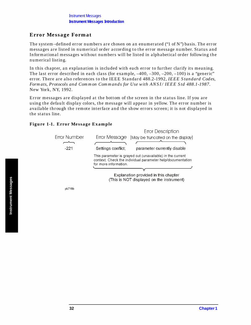
Instrument MessagesInstrument Messages Introduction
Inst
rum
ent
Mes
sag
es
Error Message Format
The system–defined error numbers are chosen on an enumerated (“1 of N”) basis. The error messages are listed in numerical order according to the error message number. Status and Informational messages without numbers will be listed in alphabetical order following the numerical listing.
In this chapter, an explanation is included with each error to further clarify its meaning. The last error described in each class (for example, –400, –300, –200, –100) is a “generic” error. There are also references to the IEEE Standard 488.2-1992, IEEE Standard Codes, Formats, Protocols and Common Commands for Use with ANSI/IEEE Std 488.1-1987. New York, NY, 1992.
Error messages are displayed at the bottom of the screen in the status line. If you are using the default display colors, the message will appear in yellow. The error number is available through the remote interface and the show errors screen; it is not displayed in the status line.
Figure 1-1. Error Message Example
32 Chapter 1
Instrument MessagesInstrument Messages Introduction
Instru
men
t Messag
es
Error Message Types
Events do not generate more than one type of error. For example, an event that generates a query error will not generate a device-specific, execution, or command error.
−499 to −400: Query Errors
These errors indicate that the analyzer output queue control has detected a problem with the message exchange protocol described in IEEE 488.2, Chapter 6. Errors in this class set the query error bit (bit 2) in the event status register (IEEE 488.2, section 11.5.1). These errors correspond to message exchange protocol errors described in IEEE 488.2, 6.5. In this case:
• Either an attempt is being made to read data from the output queue when no output is either present or pending, or
• Data in the output queue has been lost.
−399 to −300: Device-Specific Errors
An error number in the range –399 to –300 indicates that the analyzer has detected an error where some device operations did not properly complete, possibly due to an abnormal hardware or firmware condition. This is not a error in response to a SCPI query or command, or command execution. The occurrence of any error in this class will cause the device-specific error bit (bit 3) in the event status register to be set.
−299 to −200: Execution Errors
These errors indicate that an error has been detected during analyzer execution.
−199 to −100: Command Errors
These errors indicate that the analyzer parser detected an IEEE 488.2 syntax error. Errors in this class set the command error bit (bit 5) in the event status register (IEEE 488.2, section 11.5.1). In this case:
• Either an IEEE 488.2 syntax error has been detected by the parser (a control-to-device message was received that is in violation of the IEEE 488.2 standard. Possible violations include a data element which violates device listening formats or whose type is unacceptable to the device.), or
• An unrecognized header was received. These include incorrect device-specific headers and incorrect or unimplemented IEEE 488.2 common commands.
64 to 799: Device-Specific Errors
These errors indicate that a device operation did not properly complete, possibly due to an abnormal hardware or firmware condition. These codes are also used for self-test response errors. Errors in this class set the device-specific error bit (bit 3) in the event status register (IEEE 488.2, section 11.5.1).
The <error_message> string for a positive error is not part of the SCPI standard. A positive error indicates that the analyzer detected an error within the GPIB system, within the analyzer firmware or hardware, during the transfer of block data, or during calibration.
Greater than 10000: Measurement Applications Errors
These errors indicate that an error has been detected while executing measurements requiring a personality option such as the GSM Measurement Personality or those measurements found under the MEASURE front-panel key in SA mode.
Chapter 1 33
Instrument MessagesInstrument Messages
Inst
rum
ent
Mes
sag
es
Instrument Messages
Error Messages
NOTE Error numbers are displayed in the error queue, not on the display.
To see an error number, press System, Show Errors.
None Hardware Fail
ESA message NOT USED
A hardware failure has occurred. Get in touch with your service center.
0: No Error
0 No error
The queue is empty. Either every error in the queue has been read, or the queue was cleared by power-on or *CLS.
−499 to −400: Query Errors
NOTE Error numbers are displayed in the error queue, not on the display.
To see an error number, press System, Show Errors.
–440 Query UNTERMINATED after indefinite response
Indicates that a query was received in the same program message after a query requesting an indefinite response was executed (see IEEE 488.2, 6.3.7.5).
–430 Query DEADLOCKED
Indicates that a condition causing a DEADLOCKED query error occurred (see IEEE 488.2, 6.3.1.7). For example, both the input buffer and the output buffer are full and the analyzer cannot continue. The analyzer automatically discards output to correct the deadlock.
–420 Query UNTERMINATED
Indicates that a condition causing an UNTERMINATED query error occurred (see IEEE 488.2, 6.3.2.2). For example, the device was addressed to talk and an incomplete program message was received.
–410 Query INTERRUPTED
Indicates that a condition causing an INTERRUPTED query error
34 Chapter 1
Instrument MessagesInstrument Messages
Instru
men
t Messag
es
occurred (see IEEE 488.2, 6.3.2.7). For example, a query was followed by DAB or GET before a response was completely sent.
−400 Query Error
This is a generic query error for devices that cannot detect more specific errors. The code indicates only that a query error as defined in IEEE 488.2, 11.5.1.1.7 and 6.3 has occurred.
−399 to −300: Device-Specific Errors
NOTE Error numbers are displayed in the error queue, not on the display.
To see an error number, press System, Show Errors.
−340 Calibration failed
The instrument requires an Align All Now. Restore the alignment by pressing System, Alignments, Align All Now.
−330 Self-test failed; EEPROM checksum for <card>
The card identification header for a hardware card is incorrect. If the card is not properly identified, the instrument is likely to be non-functional. Report this error to the nearest Agilent Technologies sales or service office.
−321 Out of memory
An internal operation needed more memory than was available. Report this error to the nearest Agilent Technologies sales or service office.
−310 System error; Pretune DAC Calibration failed
System error; Pretune DAC Cal failed midpoint verification
System error
An internal system problem was detected. Report this error to the nearest Agilent Technologies sales or service office.
−300 Device-specific error
This is a generic device-dependent error for devices that cannot detect more specific errors. The code indicates only that a device-dependent error as defined in IEEE 488.2, 11.5.1.1.6 has occurred. Report this error to the nearest Agilent Technologies sales or service office.
−299 to −200: Execution Errors
NOTE Error numbers are displayed in the error queue, not on the display.
To see an error number, press System, Show Errors.
Chapter 1 35
Instrument MessagesInstrument Messages
Inst
rum
ent
Mes
sag
es
−253 Corrupt media
A removable media was found to be bad or incorrectly formatted. Any existing data on the media may have been lost.
−250 Mass storage error; EEPROM write timeout on EEPROM
Failure to initialize EEPROM. Report this error to the nearest Agilent Technologies sales or service office.
−241 Hardware missing
Hardware missing; no such SIO address
Missing device hardware. For example, an option is not installed.
−230 Data corrupt or stale
Data corrupt or stale; EEPROM copy of <file>
Data corrupt or stale; NRAM copy of <file>
Possibly invalid data. A new measurement was started but not completed.
−224 Illegal parameter value
You have sent a parameter for this command that is not allowed. See the Function Reference.
−223 Too much data; not all points entered
Too much data; <description of the type of data exceeded>
Indicates that a legal program data element of block, expression, or string type was received that contained more data than the device could handle due to memory or related device-specific requirements.
−222 Data out of range
A legal program data element was parsed but could not be executed because the interpreted value was outside the legal range defined by the device (see IEEE 488.2 11.5.1.1.5). The displayed results may be clipped.
−221 Settings conflict;…
…Averaging unavailable when Sig ID is on
User in ext mix with Sig ID on and try to select Averaging Mode.
…Cannot center unpreselected external mixer
Mixer Type is Unpreselected and user tries Preselector Centering.
…Command incompatible with band pair marker
Using remote commands, you have tried to adjust the start or stop frequency of a span pair marker. You can adjust only the center and span.
36 Chapter 1

Instrument MessagesInstrument Messages
Instru
men
t Messag
es
…External mixing unavailable when preamp on
Internal preamp is on and user tries to select external mixing.
…FFT unavailable when Sig ID is on
User in ext mix with Sig ID on and try to select Manual:FFT
…Settings Conflict, Preamp unavailable in external mixing mode
User in ext mix and tries turning on internal preamp.
…Sig ID requires EXTERNAL mixing mode
Input Mixer setting is INTERNAL and the user tries Sig ID.
…Sig ID unavailable in Manual:FFT
User in ext mix, in FFT, user tries Sig ID.
…Sig ID unavailable when Averaging is on
User in ext mix, in Averaging Mode, user tries Sig ID.
…Sig ID unavailable when Signal Track is on
User in ext mix, in Signal Track Mode, user tries Sig ID.
…Signal ID unavailable with Presel Mixer
User in Presel mixer, and tries to turn on Sig ID.
…Signal Track unavailable when Sig ID is on
User in ext mix with Sig ID on and try to select Signal Track.
Settings conflict; parameter currently disabled
This parameter is grayed out (unavailable) in the current context. Check the individual parameter help/documentation for more information.
−200 Execution Error
For devices that cannot detect more specific errors, this code indicates only that an execution error as defined in IEEE 488.2, 11.5.1.1.5 has occurred.
−199 to −100: Command Errors
NOTE Error numbers are displayed in the error queue, not on the display.
To see an error number, press System, Show Errors.
Chapter 1 37

Instrument MessagesInstrument Messages
Inst
rum
ent
Mes
sag
es
–178 Expression data not allowed
A legal expression data was encountered, but was not allowed by the device at this point in parsing.
–171 Invalid expression
The expression data element was invalid (see IEEE 488.2, 7.7.7.2). For example, unmatched parentheses or an illegal character.
–170 Expression data error
This error, as well as errors –171 through –179, is generated when parsing an expression data element. This particular error message is used if the device cannot detect a more specific error.
–168 Block data not allowed
A legal block data element was encountered, but not allowed by the device at this point in the parsing.
–161 Invalid block data
A block data element was expected, but was invalid (see IEEE 488.2, 7.7.6.2). For example, an END message was received before the end length was satisfied.
–160 Block data error
This error, as well as errors –161 through –169, is generated when parsing a block data element. This particular error message is used if the device cannot detect a more specific error.
–158 String data not allowed
A string data element was encountered, but not allowed by the device at this point in the parsing.
–151 Invalid string data
A string data element was expected, but was invalid (see IEEE 488.2, 7.7.5.2). For example, an END message was received before the terminal quote character.
–150 String data error
This error, as well as errors –151 through –159, is generated when parsing a string data element. This particular error message is used if the device cannot detect a more specific error.
–148 Character data not allowed
A legal character data element was encountered where prohibited by the device.
38 Chapter 1
Instrument MessagesInstrument Messages
Instru
men
t Messag
es
–144 Character data too long
The character data element contains more than twelve characters (see IEEE 488.2, 7.7.1.4).
–141 Invalid character data
Either the character data element contains an invalid character or the particular element received is not valid for the header.
–140 Character data error
This error, as well as errors –141 through –149, is generated when parsing a character data element. This particular error message is used if the device cannot detect a more specific error.
–138 Suffix not allowed
A suffix was encountered after a numeric element which does not allow suffixes.
–134 Suffix too long
The suffix contained more than twelve characters (see IEEE 488.2, 7.7.3.4).
–131 Invalid suffix
Attempt to send a SCPI command with a suffix that does not match the current units for the function.
The suffix does not follow the syntax described in IEEE 488.2, 7.7.3.2, or the suffix is inappropriate for this device.
–130 Suffix error
This error, as well as errors –131 through –139, is generated when parsing a suffix. This particular error message is used if the device cannot detect a more specific error.
–128 Numeric data not allowed
A legal numeric data element was received, but the device does not accept one in this position for the header.
–124 Too many digits
The mantissa of a decimal-numeric data element contained more than 255 digits excluding leading zeros (see IEEE 488.2, 7.7.2.4.1).
–123 Exponent too large
The magnitude of an exponent was greater than 32000 (see IEEE 488.2, 7.7.2.4.1).
–121 Invalid character in number
An invalid character for the data type being parsed was encountered. For example, an alpha in a decimal numeric or a “9” in octal data.
Chapter 1 39
Instrument MessagesInstrument Messages
Inst
rum
ent
Mes
sag
es
−120 Numeric data error; VGR
Numeric data error
This error, and errors −121 through −129, is generated when parsing a data element that appears to be numeric, including non-decimal numeric types. This message is used if the device cannot detect a more specific error.
–114 Header suffix out of range
The value of a header suffix attached to a program mnemonic makes the header invalid.
–113 Undefined header
The header is syntactically correct, but it is undefined for this specific device. For example, *XYZ is not defined for any device.
–112 Program mnemonic too long
The header contains more than twelve characters (see IEEE 488.2, 7.6.1.4.1).
–111 Header separator error
A character which is not a legal header separator was encountered while parsing the header.
–110 Command header error
An error was detected in the header. This message is used when the device cannot detect the more specific errors described for errors –111 through –119.
–109 Missing parameter
Fewer parameters were received than required for the header. For example, the *ESE common command requires one parameter, so receiving *ESE is not allowed.
–108 Parameter not allowed
More parameters were received than expected for the header. For example, the *ESE common command only accepts one parameter, so receiving *ESE 0,1 is not allowed.
–105 GET not allowed
A Group Execute Trigger was received within a program message (see IEEE 488.2, 7.7). Correct the GPIB controller program so that the GET does not occur within a line of GPIB program code.
–104 Data type error
The parser recognized a data element that is not allowed. For example, numeric or string data was expected, but block data was encountered.
40 Chapter 1
Instrument MessagesInstrument Messages
Instru
men
t Messag
es
–103 Invalid separator
The parser was expecting a separator and encountered an illegal character. For example, the semicolon was omitted after a program message unit.
–102 Syntax error
An unrecognized command or data type was encountered. For example, a string was received when the device does not accept strings.
–101 Invalid character
A syntactic command contains a character which is invalid for that type. For example, a header containing an ampersand, such as “SETUP&”. This error might be used in place of error numbers –114, –121, –141, and some others.
−100 Command error
This is a generic syntax error for devices that cannot detect more specific errors. The code indicates only that a command error as defined in IEEE 488.2, 11.5.1.1.4 has occurred.
64 to 799: Device-Specific Errors
64 System, Alignments, Align All Now, Needed
102 There is too much 50 MHz energy at the RF port for alignments to run. Reduce input power and run alignments again.
103 Sampling Oscillator Unlock; Failure acquiring SO frequency lock
Report this error to the nearest Agilent Technologies sales or service office.
104 1st LO Unlock; Failure acquiring FracN LO frequency lock
1st LO Unlock; Failure acquiring single loop FracN LO lock
The first LO on has lost phase lock. Report this error to the nearest Agilent Technologies sales or service office.
105 2nd LO Unlock
The second LO has lost phase lock. Report this error to the nearest Agilent Technologies sales or service office.
106 4th LO Unlock
The fourth LO has lost phase lock. Report this error to the nearest Agilent Technologies sales or service office.
107 Sample Clock Unlock
Report this error to the nearest Agilent Technologies sales or service office.
Chapter 1 41
Instrument MessagesInstrument Messages
Inst
rum
ent
Mes
sag
es
108 Cal Oscillator Unlock
Report this error to the nearest Agilent Technologies sales or service office.
129 Meas Uncal
The measurement is uncalibrated, usually due to sweeping a narrow RBW filter too quickly. Check the sweep time, span, and bandwidth settings, or press Auto Couple.
143 Final IF Overload
Either increase input attenuation or decrease the input signal level.
163 Freq Count: Reduce Span/RBW ratio
The span is too wide for the current resolution bandwidth. Either reduce the span or increase the RBW.
187 Directory already exists
190 Unable to save file, invalid path
191 File Operation Status; directory <name> created
File Operation Status; <name> directory deleted
File Operation Status; <name> file copied
File Operation Status; <name> file deleted
File Operation Status; <name> file loaded
File Operation Status; <name> file saved
File Operation Status; Volume <name> formatted
196 Can’t Auto-Couple Sweep Time in Zero Span
197 Marker Freq Count HW Failure
201 Option not installed
The desired operation cannot be performed because a required option is not installed. For example, pressing Source with no tracking generator installed in the analyzer will generate this error.
202 No peak found
No signal peak was found that meets the criteria under Peak Search, Search Param Criteria.
204 TG Frequency Limit
The tracking generator has reached the limit of its allowable frequency range.
205 Command not recognized
Indicates that the command sent from the remote interface was not recognized. Check the programming guide for correct syntax.
42 Chapter 1
Instrument MessagesInstrument Messages
Instru
men
t Messag
es
206 Unable to initialize flatness data
A failure occurred in setting the flatness data in the internal EEROM. Get in touch with your local Agilent Technologies sales and service office.
207 Unable to store flatness data
A failure occurred in setting the flatness data in the internal EEROM. Get in touch with your local Agilent Technologies sales and service office.
208 Preselector is not available at this frequency.
Preselection of frequencies below ∼ 3 GHz is not supported. Preselector centering can be performed only for frequencies above 3.025 GHz.
209 Preselector centering failed
An attempt to center the preselector failed. You tried to center the preselector with the analyzer span too wide. Preselector centering can be performed only for spans below 1.123 GHz.
211 RBW limited to 1 kHz when Span > 5 MHz
In spans greater than 5 MHz, narrow (digital) resolution bandwidths, below 1 kHz, are not available.
213 Span limited to 5 MHz when RBW < 1 kHz
In narrow (digital) resolution bandwidths, below 1 kHz, spans greater than 5 MHz are not available.
214 TG start freq is less than 9 kHz
Tracking generator uncalibrated below 9 kHz.
215 TG start freq is less than 1/2 res bw
Tracking generator uncalibrated at start frequencies below 1/2 the current resolution bandwidth.
216 Invalid Baud Rate
Attempt to use invalid baud rate. Refer to the programming language chapter of Agilent Technologies ESA Series Spectrum Analyzer Programmer’s Guide for more information.
217 RS-232 Interface Error
An error occurred on the serial interface.
219 Command not valid in this model
Indicates that the command sent from the remote interface does not apply to this analyzer model number. For example, attempting to center the preselector in an analyzer without a preselector will generate this error.
220 Trace Menu is unavailable when Sig Ident is ON
Chapter 1 43
Instrument MessagesInstrument Messages
Inst
rum
ent
Mes
sag
es
221 Invalid option, unable to uninstall package
You have attempted to remove a personality that is not currently installed. Verify command was entered correctly.
222 Command not valid when no measurement is active
Indicates that the command sent from the remote interface must be issued while a measurement is running in the analyzer.
223 Trigger Offset unavailable in swept spans
Trigger Offset is only available in Zero Span. Refer to “Trig” in your Agilent Spectrum Analyzer User’s Guide for a description of this function.
224 Option not licensed.
The selected option requires a license. Refer to the installation procedures in the user’s guide available for this particular option.
226 Actual Trig Delay = Remote Trig Delay + Remote Trig Offset
228 Preselector centering failed - inadequate peak
You tried to center the preselector with a trace peak of insufficient level. You may have pressed Presel Center with the marker placed below the signal peak.
229 3 − 26.5 GHz preselector bypassed, can’t adjust
The microwave preselector has been bypassed. Attempts to press or send the SCPI commands for Presel Center or Presel Adjust will result in this error.
230 Unpreselected external mixing - no preselector
While using external mixing with an unpreselected mixer, attempts to press or send the SCPI commands for Presel Center or Presel Adjust will result in this error.
231 Preselector unavailable while in external mixing
The internal preselectors cannot be used while in external mixing.
232 External mixing is off, can’t adjust external preselector
The preselector is unavailable when external mixing is turned off.
238 Trace smoothing: VBW filt or Average Detector; cannot use both
239 HW Diag is OFF
332 Average Type incompatible for scale.
Amplitude Scale command should be sent prior to the Average Type command.
44 Chapter 1
Instrument MessagesInstrument Messages
Instru
men
t Messag
es
601 PSA only612 ESA only File not found
The analyzer could not find the specified file.
601 Floppy disk full
The floppy disk is full. Clear some space by deleting unwanted files.
602 PSA only605 ESA only Media is protected
A save was attempted to a write-protected device.
602 Floppy disk error
An unknown error has occurred while accessing the floppy disk.
603 PSA only615 ESA only File is corrupt
Corrupted file
The file that you were trying to load is corrupt.
604 PSA only607 ESA only File name error
File name error; Directory does not have a default file type
File name error; Directory does not support extenders
File name error; Empty filename
File name error; Illegal extender
File name error; Illegal filename character
File name error; Only one: is allowed
File name error; Only one extender character allowed
An invalid file name was specified. Use filenames with a maximum of 8 characters (letters and digits only), and use a 3-character extension. File names are not case-sensitive. This error also occurs if you try to delete a nonexistent file.
615 PSA only604 ESA only File already exists
You attempted to save to a file that already exists. Either delete or rename the existing file or select a new name, then try again.
602 PSA only605 ESA only Media is protected
A save was attempted to a write-protected device.
Chapter 1 45
Instrument MessagesInstrument Messages
Inst
rum
ent
Mes
sag
es
605 Data corrupt or stale; EEPROM copy of <file>
WARNING: Contact the factory if you see this error.
This error indicates that a file stored in EEPROM has become corrupt and the Hamming codes are unable to repair the data.
When the EEPROM file has been corrupted, the system will store default values into both the Non-Volatile RAM and EEPROM copies of the file. If this error occurs often, it may indicate that there is a problem with the physical memory.
Data corrupt or stale; RAM copy of <file>
This error indicates that a file stored in Non-Volatile RAM has become corrupt and the Hamming codes are unable to repair the data.
When a Non-Volatile file has this error, the system will first try to verify the state of the data in EEPROM and if valid it will copy the data in EEPROM into the Non-Volatile ram copy of the file. When this happens, the system will remain calibrated. If this error occurs often, it may indicate that there is a problem with the physical memory.
606 Data questionable; EEPROM copy of <file>
EEPROM error occurred. The EEPROM copy of an internal file is either corrupt or otherwise unusable. The system automatically updates the non-volatile RAM copy of the EEPROM copy using a default initialization. The actual EEPROM file is left as it is. Report this error to the nearest Agilent Technologies sales or service office.
606 Media is corrupt
A save was attempted to a corrupt device.
604 PSA only607 ESA only File name error
File name error; Directory does not have a default file type
File name error; Directory does not support extenders
File name error; Empty filename
File name error; Illegal extender
File name error; Illegal filename character
File name error; Only one: is allowed
File name error; Only one extender character allowed
An invalid file name was specified. Use filenames with a maximum of 8 characters (letters and digits only), and use a 3-character extension. File names are not case-sensitive. This error also occurs if you try to delete a nonexistent file.
46 Chapter 1
Instrument MessagesInstrument Messages
Instru
men
t Messag
es
609 Restoration of NVRAM data
This error indicates that a file stored in Non-Volatile RAM has been corrected based on the Hamming codes stored with the file. After the correction, the file will contain the same data as when the instrument was shut off. If this error continues to occur on successive power cycles, it may indicate that there is a problem with the physical memory.
627 PSA only609 ESA only Media is not writable
A save was attempted to a read-only device or device that could not be written to. Try a known-good disk.
ERROR/NUMBER “609 Restoration of NVRAM data” IS ALREADY USED FOR HAPPENING ./storage/directory/NRAM_Directory.cc HAP_nramDataCorrected
610 File access is denied
The file is protected or hidden and cannot be accessed.
611 File access IO busy; duplicate :SERVice[:PRODuction]:CALibrate:BEGin
File access IO busy; :SERVice[:PRODuction]:CALibrate:END without a BEGin
601 PSA only612 ESA only File not found
The analyzer could not find the specified file.
613 Flash memory is full
The internal flash memory is full. Clear some space by deleting unwanted files. If your analyzer has a serial number less than US41440000 or MY41440000 and Option B72 has not been installed, you may also increase the flash memory size by purchasing Option B72.
763 PSA only614 ESA only Bad, missing, or unformatted disk
Bad or missing floppy disk
The floppy disk is not inserted properly, is not formatted, or the directory cannot be read. Insert a known good disk and try again.
615 PSA only604 ESA only File already exists
You attempted to save to a file that already exists. Either delete or rename the existing file or select a new name, then try again.
Chapter 1 47
Instrument MessagesInstrument Messages
Inst
rum
ent
Mes
sag
es
603 PSA only615 ESA only File is corrupt
Corrupted file
The file that you were trying to load is corrupt.
617 Wrong density floppy inserted
The floppy disk has the wrong density. It should be 1.44 MB.
618 Illegal write access of Flash memory
Attempt to write to an unavailable area of internal flash memory.
619 Can’t Auto-Couple RBW in Zero Span
You sent a remote command to set the RBW into auto while in zero span. (Remote interface only.)
620 Can’t Auto-Couple Sweep Time in Zero Span
You sent a remote command to set the sweep time to auto while in zero span. (Remote interface only.)
622 External reference missing or out of range
The external frequency reference signal is missing, has too low an amplitude, or does not match the frequency value that you previously entered into instrument memory.
623 Printer not responding
Printer not responding; ioctl ERROR
Check the printer. It may not be connected properly or turned on.
625 Printer out of paper
Load paper in printer.
626 Print failed; Can’t open print file desc
Print failed; DisplayExport can’t create print file
Print failed; DisplayExport illegal print language
Print failed; DisplayExport insufficient RAM space
Print failed; DisplayExport undetermined error
Print failed; Error transferring image to printer
Print failed; Printer ioctl failed
Print failed; Unknown printer response
627 PSA only609 ESA only Media is not writable
A save was attempted to a read-only device or device that could not be written to. Try a known-good disk.
48 Chapter 1

Instrument MessagesInstrument Messages
Instru
men
t Messag
es
651 Connect RF OUT to INPUT
Attempt to align the tracking generator without its output connected. Connect the tracking generator RF OUT to the analyzer INPUT.
652 Connect Amptd Ref Output to Input
For Agilent Technologies E4402B, E4403B, E4404B, E4405B, E4407B, and E4408B only: you must connect the AMPTD REF OUTPUT to the analyzer INPUT with the appropriate cable.
653 Auto Align not available when using Calibration Defaults
The Auto Alignment system cannot be used until an Align Now All is executed by pressing System, Alignments, Align Now, All. On all Agilent Technologies ESA spectrum analyzer models except Agilent Technologies E4401B and E4411B, you must connect the AMPTD REF OUT to the INPUT with the appropriate cable to perform this alignment. For Agilent Technologies E4401B and E4411B only: disconnect any signals from the INPUT prior to performing this procedure.
701 Invalid printer response
In attempting to identify the printer an invalid response was received. Check that you are using a supported printer. Be sure you are using the proper cable and that it is securely fastened.
702 Unsupported printer
A printer which is recognized, but known to be unsupported was identified. This printer cannot be used with the analyzer. For example, a printer only supported by Microsoft Windows will generate this error.
703 Unknown printer
In attempting to identify the printer, a valid response was received but the printer is not known to the analyzer. Use the Custom printer menu under Print Setup to configure the printer.
704 Printer interface error
An error occurred while trying to print. Make sure the printer is turned on and properly connected.
705 Printer Type is None
The current printer type is set to None, so no print operations are possible. Change the type in the Print Setup menu and try again.
727 In <filename>: [DATA] header missing
This message indicates that the data section of a file did not begin with the token [DATA].
Chapter 1 49
Instrument MessagesInstrument Messages
Inst
rum
ent
Mes
sag
es
728 In <filename>, line <nnn>: separator missing
The [HEADER] section of a file contains entries requiring an equal (=) sign, such as <keyword> = <value>. This message appears if the equal sign does not appear on the line.
729 In <filename>: error reading file
Appears when loading data from a limit line or corrections disk file and a failure to the file occurs.
730 In <filename>, line <numeric_value>: line too long
When loading data from a limit line or corrections disk file, this message will appear if the length of any line in the file exceeds 255 characters.
731 In <command>: bad data count (<numeric_value>): expected multiple of <numeric_value>
This message indicates that the data sent to a corrections or limit table via the DATA or MERGE commands does not have the expected length for the table. For example, this message would appear if an attempt were made to merge 7 numeric values into a limit table, since each logical entry requires 3 values (frequency, amplitude, and connected).
732 In <filename>, line <numeric_value>: error parsing tokens
This message may appear when loading data from a limit line or corrections disk file. It indicates a problem in the attempt to break a string of text into tokens. There may be too few tokens in the string. In other words, the file content must match the expected format. This typically happens when there are too few numeric values in the [DATA] section of a limit or corrections file.
733 In <filename>, line <numeric_value>: <xxx> is not numeric
This message may appear when loading data from a limit line or corrections disk file. It indicates that a non-numeric token <xxx> was found where a numeric token was expected. In other words, the file content must match the expected format.
734 Interpolation error: cannot compute log of <negative_frequency_value>
Occurs when the frequency interpolation of a limit line is set to log and the start frequency of the instrument is negative. The <negative_frequency_value> is limited to– 80 MHz, so it may not match the frequency that caused the error.
735 In <filename>: bad amplitude unit <unit>
This message indicates that unit <unit> is not recognized or supported.
50 Chapter 1

Instrument MessagesInstrument Messages
Instru
men
t Messag
es
736 Too many data values at <freq_or_time_value>
This message may appear when data is sent to a corrections or limit table using the DATA or MERGE commands. These tables limit the number of amplitudes associated with a frequency or time to 2 or less. This message will appear if an attempt is made to attach 3 or more values to a frequency or time.
751 Instrument state set to initial values
Instrument state may be corrupt, state has been reset to initial values
While trying to load a trace or state, the state information was found to be in error. This may be because the state had been stored on a later revision of analyzer firmware. A default set of state variables was loaded instead. There is nothing wrong with the analyzer.
An error in the internal instrument state has been detected. The state has been reset to a default value.
752 Unable to load state from file
Attempt to load a state from a file failed.
753 Unable to save state to file
Attempt to save a state to a file failed. See the associated error messages for the cause (press System, Show Errors).
For PSA: If this error occurs after a mode switch that takes longer then normal, you may need to free up some instrument memory. When you switch to a different measurement mode, the analyzer must temporarily store instrument state data. If you have less then 500 kB of available memory, the switching process can take over 1 minute and result in this error. Use the File key menu to delete any unnecessary files from instrument memory.
755 Unable to load state from register
Attempt to load a state from an internal state register failed.
756 Unable to save state to register
Attempt to save a state to an internal state register failed. See the associated error messages for the cause (press System, Show Errors).
757 Unable to load user state, factory preset was done
A user preset failed, so the factory preset values were used. Save a valid state into user preset and try again.
758 Unable to save user state
Attempt to save a user preset state failed. See the associated error messages for the cause (press System, Show Errors).
Chapter 1 51
Instrument MessagesInstrument Messages
Inst
rum
ent
Mes
sag
es
759 Unable to load state saved from firmware Rev A.xx.xx; Restore Sys\nDefaults
Unable to load state
A saved state file from a newer firmware revision was attempted to be loaded into an older instrument.
760 ESA only Unable to query state
Query of state over the remote interface was unsuccessful.
761 ESA only Unable to set state
Attempt to set the state over the remote interface was unsuccessful.
762 ESA only Incorrect filename, allowable extensions are .trc or .csv
Attempt to save a trace to a file with an incorrect extension.
762 ESA only Unable to load file
A failure occurred while loading a file; the file was not loaded.
763 PSA only614 ESA only Bad, missing, or unformatted disk
Bad or missing floppy disk
The floppy disk is not inserted properly, is not formatted, or the directory cannot be read. Insert a known good disk and try again.
763 ESA only Incorrect filename, allowable extensions are .gif or .wmf
Attempt to save a screen image to a file with an incorrect extension.
764 Unable to save file
Attempt to save a file failed; the file was not saved. See the associated error messages for the cause (press System, Show Errors).
765 Unable to load file
Attempt to load a file failed; the file was not loaded.
766 Unable to format drive
767 Failed to Initialize ISTATE regions. Fatal LDS error
Attempt to initialize the instrument state has failed. Cycle instrument power. If this fails to correct the problem, contact your nearest Agilent Technologies service center.
768 Unable to load user state, required instrument mode is not installed
Attempt to load a state failed, because the state was saved with a measurement personality that is not currently loaded. Load the appropriate personality and try again.
52 Chapter 1
Instrument MessagesInstrument Messages
Instru
men
t Messag
es
769 ESA only Invalid instrument mode
You have attempted to switch to an instrument mode that is currently not installed. Confirm that the mode name (for INST:SEL) or number (for INST:NSEL) was entered correctly and that the requested personality is actually installed in the instrument.
770 Incorrect filename, allowable extensions are .gif or .wmf
You sent a remote command to save a screen file but did not specify a valid extension.
Incorrect filename, allowable extension is .sta
You sent a remote command to save a state file but did not specify a valid extension.
Incorrect filename, allowable extensions are .trc or .csv
You sent a remote command to save a trace file but did not specify a valid extension.
770 Instrument mode requested is not supported
Instrument mode specified with: INST command is not valid. Refer to Chapter 5, “Instrument Subsystem” of Agilent Technologies ESA Series Spectrum Analyzer Programmer’s Guide for more information.
771 Store Ref trace before turning on Normalize
A reference trace must be available for the Normalize function to be activated. Refer to “View/Trace” in the Agilent ESA Spectrum Analyzer User’s Guide where the Normalize key function is explained in detail.
772 Cannot load a directory
Cannot load a directory, please choose a file
You have selected a directory instead of a file when attempting to perform the Load function under the File front-panel key.
780 No Peak Found
781 Video Trigger cannot be active with Average Detector
You sent a remote command to do one of the following:
• Turn on video trigger while the Average Detector or a Marker Function is active.
• Turn on the Average Detector or a Marker Function while Video Trigger is active.
782 Video Trigger cannot be used with Mkr Func due to Average Detector
783 Allowable span for current center frequency exceeded
784 Allowable CF for current span exceeded
Chapter 1 53
Instrument MessagesInstrument Messages
Inst
rum
ent
Mes
sag
es
787 WBIF Self Test Failed
Variable resistor 122 performs a loop-back self-test on power up. It does an ADC image calibration, then stores a sine wave in RAM and plays it out the DAC. It then measures the carrier power, image rejection and signal-to-noise ratio. If this test fails, the wideband IF pc assemblies are either incorrectly installed or have a hardware failure. Call your Agilent Service Representative.
There is diagnostic information available for the CE. The self test can be run with DIAG:WBIF:TEST? This command returns 4 values: passed, carrier power, image rejection and signal-to-noise ratio.
First look at the carrier power. If it is below –50, the LVDS cable is probably missing or faulty. If the carrier power is above 0 dBm, image rejection less than 40 but signal-to-noise ratio is more than 50, there is probably a bad ADC.
788 WBIF ADC Image Calibration Failed
The Opt 122 card uses two ADCs that must be kept in perfect synchronization to avoid unwanted images appearing in the spectrum. The instrument will occasionally perform an ADC Image Calibration (formerly known as Step Cal) to re-synchronize the ADCs. This calibration is only known to fail if there is a hardware problem.
789 WBIF Firmware Reset
Opt 122 has a local microprocessor controlling the hardware trigger. If this microprocessor resets, it will automatically restart and begin taking data again, posting this notice to the user. While this should never happen, it is a self-recovering error that requires no action on the part of the user. If, however, it starts to occur frequently, contact your Agilent service representative to find out if there is a firmware upgrade to solve this problem.
791 Acquiring Data...
795 No trigger before timeout; auto-triggered
797 Awaiting Trigger, no AUTO Trig
801 Memory limit caused Data Acquisition to be truncated
805 doing Alignment...
Greater than 10000: Measurement Applications Errors
NOTE Error numbers are displayed in the error queue, not on the display.
To see an error number, press System, Show Errors.
54 Chapter 1
Instrument MessagesInstrument Messages
Instru
men
t Messag
es
10008 to 10517: Power Suite Error Messages An error number in this range indicates the instrument has detected an error relating to the Power Suite functionality.
10008 Preferred resolution bandwidth not available.
The calculated required resolution bandwidth for this measurement is not available.
10010 One or more harmonics past freq limit: number decreased.
Highest harmonic was past the frequency limit of the analyzer, so the number of measured harmonics was decreased.
10011 First harmonic is past analyzer frequency limit.
First harmonic was past the frequency limit, so no harmonics can be measured. The analyzer will simply measure the fundamental. If you have the Agilent E4407B analyzer, Option AYZ allows the use of HP/Agilent 11970 Series, and HP/Agilent 11974 external mixers to extend the frequency range to 110 GHz. Operation to 325 GHz is also possible with non-HP/Agilent mixers.
10012 No Fundamental > 0 Hz found in given span.
There were no frequencies greater than 0 Hz in the starting span, so the centre frequency at measurement entry will be used as the fundamental.
10013 No Fundamental > -50 dBm found in given span.
There was no fundamental found, so the centre frequency at measurement entry will be used as the fundamental.
10020 Signal Tracking is not available when Noise Correction is on.
If signal tracking is turned on while noise correction is on, it will be turned off. To use the signal tracking function, first turn noise correction off.
10138 Valid GSM burst not found in frame (Burst Type)
No active GSM bursts that match the selected burst type have been detected in the RF input signal. Search was performed over a complete GSM frame.
10139 Valid GSM burst not found in specified timeslot (Burst Type)
No active GSM bursts that match the selected burst type have been detected in the RF input signal. Search was performed over the specified timeslot.
10140 Valid GSM burst not found in frame (Ref Burst)
No active GSM bursts that match the selected burst type have been detected in the RF input signal. Search was performed over the specified complete GSM frame using the Ref Burst type setting.
Chapter 1 55
Instrument MessagesInstrument Messages
Inst
rum
ent
Mes
sag
es
10141 Sync word not found in frame (Burst Type)
One or more active GSM bursts that match the selected burst type have been detected in the RF input signal, but none contain the selected Training Sequence Code (TSC). The search was performed over the complete GSM frame.
10142 Sync word not found in specified timeslot (Burst Type)
One or more active GSM bursts that match the selected burst type have been detected in the RF input signal, but none contain the selected Training Sequence Code (TSC). The search was only performed over the specified timeslot setting.
10143 Sync word not found in frame (Ref Burst)
One or more active GSM bursts that match the selected burst type have been detected in the RF input signal, but none contain the selected Training Sequence Code (TSC). The search was only performed using the Reference Burst type and the Ref TSC settings over the complete GSM frame.
10144 Unknown demod status
Demodulation is in an unknown state. Press Preset. If the error persists, get in touch with your service center.
10145 Opt AYX hardware required. Meas unavailable.
Option AYX must be installed for this measurement to be enabled.
10146 Options B7D & B7E hardware required. Meas unavailable.
The RF Communications Hardware (Option B7E) and Digital Signal Fast ADC (Option B7D) cards required to perform the demodulation are not present in the analyzer.
10147 Opt B7D bootrom requires upgrade.
The (Option B7D) bootrom revision is not supported by the currently loaded personality version. Refer to the user’s guide for the personality in use.
10148 Opt BAH DSP algorithm files not installed. Meas unavailable. Contact your Service Center.
The Digital Signal Processor algorithm files required to perform the demodulation are not present in the analyzer.
10148 B7D DSP Code Fail. Reload Opt BAH. Contact your Service Center.
The Digital Signal Processor algorithm files required to perform the demodulation are not present in the IDSP: drive.
56 Chapter 1
Instrument MessagesInstrument Messages
Instru
men
t Messag
es
10149 Opt BAH DSP algorithm code file requires upgrade.
The Digital Signal Processing algorithm code file revision is not supported by the currently loaded personality version. Refer to the user’s guide for the personality in use for more information on installation/upgrade.
10150 Opt BAH DSP algorithm coef. file requires upgrade.
The Digital Signal Processor algorithm coefficient file revision is not supported by the currently loaded personality version. Refer to the user’s guide for the personality in use.
10151 Opt BAH DSP algorithm files failed to load, aborting measure.
The Digital Signal Processor algorithm files required to perform the demodulation are corrupt and cannot be loaded properly. Reinstall measurement personality.
10151 B7D DSP Code Fail. Reload Opt BAH. Contact your Service Center.
The Digital Signal Processor algorithm files required to perform the demodulation are present in the IDSP: drive and cannot be loaded properly into DSP RAM. Reinstall measurement personality.
10152 Lost trigger, aborting measurement.
The selected trigger source was present at the start of the measurement, but timed out before the measurement completed.
10153 DSP algorithm timeout, aborting measurement
The Digital Signal Processor demodulation algorithm timed-out for an unknown reason. This message normally indicates a problem with the modulated signal.
10154 Measurement not defined for Out of Band.
You have changed to an out-of-band frequency range. The band measurement only operates in the selected band.
10155 No Fast ADC hardware installed. Meas unavailable.
The analyzer cannot use sweep times of less than 5 msec when Option B7D or Option AYX is not installed. Therefore, the measurement will not be executed.
10156 No Fast ADC hardware installed.
The analyzer cannot use sweep times of less than 5 msec when Option B7D or Option AYX is not installed resulting in all the radio standards not being supported.
10156 The calibration data is invalid, and has been cleared.
10157 Tracking Generator hardware is not present. Meas unavailable.
The measurement requires a built-in tracking generator.
Chapter 1 57
Instrument MessagesInstrument Messages
Inst
rum
ent
Mes
sag
es
10158 This operation requires a measurement to be active.
10159 Entire trace is below threshold level
The measurement cannot operate properly because the trace has completely fallen below the threshold level. Change the threshold level to view trace.
10160 Valid burst not found
Cannot find a valid burst, either because it is not fully on the display, or the level is too low to be detected properly.
10160 Upper Custom Mask is Invalid!
The user-specified upper custom mask cannot be resolved into a limit line. The format may be bad.
10161 No Fast ADC hardware installed.
Cannot use sweeptimes less than 5 ms, due to the lack of a fadc, therefore the meas will be severely restricted.
10161 Lower Custom Mask is Invalid!
The user-specified lower custom mask cannot be resolved into a limit line. The format may be bad.
10162 Resolution BW <300 kHz.
This error message is a warning that the resolution bandwidth has been set below 300 kHz. The test results will not meet GSM specifications.
10163 Cannot find the Power vs Time Limits File.
The limit line definition file for the GSM standards has been deleted. This message is displayed while the Measure key is grayed out. Reinstall the GSM measurement personality.
10164 Band Measurement not defined for Out of Band.
You are attempting to monitor the band but have set the frequency outside the band. Reset the band for the particular standard for which you are testing or use the channel setting which does not require a frequency to be set. (Meas Setup, Method (Channel)).
10165 Carrier Not Present.
10166 Cannot update the list of cable types.
The cable file may have been moved or deleted accidentally. Reinstall the measurement personality. This message is applicable to the GSM (Option BAH) and Distance to Fault (Option 226) measurement personality options.
58 Chapter 1

Instrument MessagesInstrument Messages
Instru
men
t Messag
es
10166 Cannot locate the file that contains the list of cable types.
The cable file may have been moved or deleted accidentally. Reinstall the measurement personality. This message is applicable to the GSM (Option BAH) and Distance to Fault (Option 226) measurement personality options.
10167 The file containing the list of cable types has been updated.
10168 Cannot update the list of cable types on drive C:
The file update failed.
10170 The Cable Fault Measurement is active. Mode Setup is disabled.
Mode setup is not available in the cable fault utility.
10172 Sweep Time too fast (<2 sec)
The sweep time must be set to 2 seconds or longer for the results to be valid.
10173 Carrier Not Present.
10177 There are no spurs to inspect.
You have attempted to switch the Inspect Spur menu key to the On position after the measurement has finished, but found no spurs.
10178 Carrier Not Present.
10179 Carrier Present. Test Stopped!
A carrier was found in the transmit band. Either disable the carrier or insert a bandpass filter for the receive bandwidth.
10180 Gate option not installed. Results may not be accurate.
This measurement method requires the use of the time-gate (option 1D6) in order to gate the spectrum during the 50-90% part of the burst. If the gate option is not installed, the measurement will still run although this warning will be displayed.
10181 Upper Custom Mask is Invalid!
The user-specified upper custom mask cannot be resolved into a limit line. The format may be bad.
10182 Lower Custom Mask is Invalid!
The user-specified lower custom mask cannot be resolved into a limit line. The format may be bad.
10183 Resolution BW < 300kHz.
The test will not meet EDGE specifications because the resolution BW has fallen below 300 kHz.
Chapter 1 59

Instrument MessagesInstrument Messages
Inst
rum
ent
Mes
sag
es
10184 Cannot find the Power vs Time Limits File.
Cannot find the limit line definition file for the EDGE standards. This message is displayed while the Measure key is grayed out.
10185 Gate option not installed. Results may not be accurate.
10186 Measurement does not support the current radio standard.
The measurement you have chosen is currently greyed out. Select a radio standard which is supported or configure this measurement manually (Mode Setup, Radio Std. None).
10186 EDGE EVM only supports EDGE TCH burst type (Burst Type)
10187 Radio standard is not supported by the current measurement.
The standard you have chosen is currently greyed out. Select a radio standard which is supported by the current measurement or configure this measurement manually (Mode Setup, Radio Std. None).
10187 EDGE ORFS only supports EDGE TCH burst type (Burst Type)
10188 EDGE PVT only supports EDGE TCH burst type (Burst Type)
10189 EDGE PVT only supports EDGE TCH burst type (Ref Burst)
10190 Select a valid Radio Standard/Measurement combination to enable.
The Enable All Measurements menu key was pressed when it was disabled. To enable select a radio standard that is supported by the current measurement or a measurement that supports the current radio standard.
10190 EDGE ORFS only supports EDGE TCH burst type (Ref Burst)
10191 Mask unavailable for current Span - increase to display mask.
The current span setting is either narrower than the mask width or so wide that there are too few display points to allow the mask to be drawn. Increase or decrease the span to display the mask.
10191 EDGE EVM only supports EDGE TCH burst type (Ref Burst)
10192 Sweep Point/Span ratio below minimum - results may be inaccurate.
The sweep point to span ratio is below the minimum required to ensure the bucket ratio is large enough to test DVB-T masks
10218 Hardkeys are disabled.
Some of the forms (for example Receiver Spurious in GSM) do not allow you to close the form without either formally accepting or cancelling the form settings. For this reason, all of the hardkeys are disabled until you terminate the form.
60 Chapter 1
Instrument MessagesInstrument Messages
Instru
men
t Messag
es
10219 Awaiting trigger
The measurement requires a trigger to be present. If the trigger does not occur or is delayed, this message will be displayed. Check your trigger settings.
10227 Measurement suspended until carrier is turned off.
The receive channel power and the receive spur measurements are specified with the attenuation set to 0 dB. To prevent overload, the frequency spectrum of interest is monitored for signal levels which exceed a specified threshold before setting the attenuator to 0 dB. If a carrier is found, this message is displayed and the completion of the measurement will not occur until the carrier is removed. The carrier check may be turned off using the properties form under the front-panel Mode Setup key. You may also change the signal threshold which determines a carrier on the properties form.
10228 Cannot correlate to input signal.
This error is normally generated because of one of the following reasons: 1. There is no carrier signal.2. Walsh channels other than the pilot are active. 3. There is some other modulation problem that will prevent the measurement from being made. This problem must be corrected before the measurement can continue.
10229 The regression portion failed.
This message occurs when (Option B7D) is not functioning properly. Demodulation measurements (modulation accuracy and code domain) might fail as a result of this error.
10230 DSP timed out, resetting DSP.
Digital Signal Processor was unable to finish the selected measurement within the given period of time. Restart the measurement.
10231 Measurement failed for unknown reasons.
Check instrument settings and restart measurement.
10232 RF Signal not found.
This message is generated if there is no signal at the center frequency that is greater than 10 dB above the displayed average noise level.
10233 Level is low, results may degrade.
The signal being measured is of low power. The results may not be as accurate as they would be if the signal level was higher.
10237 RF Board LO Unlocked. Contact service center.
This message occurs if the local oscillator on the (Option B7E) is in an unlocked state. This indicates broken hardware.
Chapter 1 61
Instrument MessagesInstrument Messages
Inst
rum
ent
Mes
sag
es
10238 RF Board SR Osc Unlocked. Contact service center.
This message occurs if the sample rate (SR) oscillator on Option B7E is in an unlocked state. This indicates broken hardware.
10239 Opt Freq Ref setting does not match external reference.
This message is generated if Source is set to External on the properties form under the front-panel Mode Setup key and the frequency on the same form is set to a frequency that does not match the frequency of the signal being used as the external reference.
10240 RF Board RF Osc Unlocked. Contact service center.
This message occurs if the reference oscillator on the (Option B7E) is in an unlocked state. This indicates broken hardware.
10241 RF Board could not detect any bursts in signal.
This message is generated when the trigger is set to RF Burst and (Option B7E) cannot detect a burst.
10245 Error reading file: SPCLIMIT.CSV. Cannot use custom limits.
The file could be missing or corrupt. Create a new limits file. Alternatively, the actual limits defined in the file might not allow the measurement to be executed. Redefine the limits or use the default limits. Restart the measurement.
10246 Error reading file: CDMASTUN.CSV. Please reinstall cdmaOne.
The file is missing or corrupt. Please reinstall the cdmaOne personality.
10247 Error reading file: CDPDMDA. Please reinstall cdmaOne.
The file is missing or corrupt. Please reinstall the cdmaOne personality.
10248 Error reading file: CDPPMCO. Please reinstall cdmaOne.
The file is missing or corrupt. Please reinstall the cdmaOne personality.
10249 Error reading file: CDPPMDA. Please reinstall cdmaOne.
The file is missing or corrupt. Please reinstall the cdmaOne personality.
10250 Error reading file: RHODMDA. Please reinstall cdmaOne.
The file is missing or corrupt. Please reinstall the cdmaOne personality.
10251 Error reading file: RHOPMCO. Please reinstall cdmaOne.
The file is missing or corrupt. Please reinstall the cdmaOne personality.
10256 Error reading file: OOBSTAB.CSV. Use Edit Table | Save Table.
This error is generated when you try to load a table (using the Load Table key on page 2 of the edit table form menu) before a table has been saved. You must first save a table using the Save Table key before trying to load a table using the Load Table key.
62 Chapter 1
Instrument MessagesInstrument Messages
Instru
men
t Messag
es
10259 Table could not be saved.
This message occurs if the C: drive is full or corrupt. Check the amount of space left on the drive.
10260 Table could not be loaded.
When trying to load a table, the previous table has been somehow corrupted. Use the Save Table key to save a valid table. Then edit the valid table, save it, and try to load it again.
10264 Emission bandwidth not found. Consider increasing span.
This error is normally generated when attempting occupied bandwidth measurements. The “X dB” value you entered (Meas Setup, X dB) to calculate the emission bandwidth is the difference between the highest point on the trace and the point “X dB” down on either side of the maximum. If the actual difference is less than the value entered, the emission bandwidth cannot be computed. Some responses to this situation are as follows:
1. Connect a signal to the input. (If there is no signal present, the difference between the trace minimum and maximum will generally be less than “X dB”.)
2. Increase the span. (If the signal is wide, the shoulders of the signal might not be present on the screen, and again, the difference between the trace minimum and maximum will be less than “X dB”.)
3. Center the signal. (There must be a point on the trace that is “X dB” down from the maximum on both sides of that maximum.)
10286 Burst not found.
Either the signal being analyzed has insufficient power, the rising or falling edges cannot be detected, or the burst is less than 126 microseconds.
10287 Valid Bluetooth burst not found. (Check Packet Type)
The burst that has been found does not correspond to the currently selected Bluetooth packet type (the burst length may be too short).
10288 Option B7D or AYX FADC hardware required. Meas unavailable.
The measurement you are attempting requires either the DSP and Fast ADC (Option B7D) or the Fast ADC (Option AYX) card to perform the demodulation, but neither are present in the analyzer.
10289 Opt 106 demod hardware required. Meas unavailable.
A demod measurement was attempted with no Bluetooth FM demod card present (Option 106).
Chapter 1 63
Instrument MessagesInstrument Messages
Inst
rum
ent
Mes
sag
es
10290 Parameter unavailable in demod measurements.
You have selected (by remote SCPI command) either RF Amplitude sync or Video trigger while running one of the demod measurements.
10291 Opt B7E RF hardware required. RF Burst unavailable.
You have selected (by remote SCPI command) RF Burst Trigger with no digital demodulation RF card present (RF Communications Hardware (Option B7E)).
10320 Opt 106 hardware required. Preamble sync unavailable.
You have selected (by remote SCPI command) preamble sync with no Bluetooth FM demodulation card present (Option 106).
10321 Start Marker must be at least 1% < Stop Marker.
You have attempted to input a start marker value that will result in the difference between the start and stop markers being less than 1%.
10322 Stop Marker must be at least 1% > Start Marker.
You have attempted to input a stop marker value that will result in the difference between the start and stop markers being less than 1%.
10323 Unable to Calculate Result using Current Setup.
You have changed the setup parameters such that the marker lines used to measure the power cannot be displayed therefore accurate measurements cannot be made.
10340 ’10101010’ pattern not detected - results may be inaccurate.
This message is displayed if the measurement cannot detect the ‘10101010’ pattern in the payload. The measurement will continue and carry out the calculations on the payload data supplied, but may not be correct.
10350 Payload data pattern ‘10101010’ not present.
This message is displayed when the “Payload Data” parameter is set to Auto and the measurement has not detected either of the required patterns in the payload.
10351 Required payload data pattern ‘10101010’ not present.
This message is displayed after successfully measuring and holding the ‘11110000’ pattern if the measurement is restarted and the ‘10101010’ data pattern is not detected.
10352 Required payload data pattern ‘11110000’ not present.
This message is displayed after successfully measuring and holding the ‘10101010’ pattern if the measurement is restarted and the ‘11110000’ data pattern is not detected.
64 Chapter 1

Instrument MessagesInstrument Messages
Instru
men
t Messag
es
10353 There is no valid result to hold.
You have attempted to hold either ∆ f1 or ∆f2 before it has been measured.
10360 Can’t compute result - not enough transitions.
This message is displayed when the measurement cannot find either a 111, 000, 101 or 010 pattern and is therefore unable to calculate the low or high frequency deviations.
10389 Valid EDGE burst not found in frame (Burst Type)
No active EDGE bursts that match the selected burst type have been detected in the RF input signal. Search was performed over the complete EDGE frame.
10390 Valid EDGE burst not found in specified timeslot (Burst Type)
No active EDGE bursts that match the selected burst type have been detected in the RF input signal. Search was performed over the specified timeslot.
10391 Valid EDGE burst not found in frame (Ref Burst)
No active EDGE bursts that match the selected burst type have been detected in the RF input signal. Search was performed over the specified complete EDGE frame using the Ref Burst setting.
10392 B7D DSP Code Fail. Reload Opt. 202. Contact your Service Center
The DSP algorithm files required to perform the demodulation are not present in the instrument ISDP: drive.
10393 Opt 252 DSP algorithm code file requires upgrade.
10394 Opt 252 DSP algorithm coef. file requires upgrade.
10395 B7D DSP Code Fail. Reload Opt. 202. Contact your Service Center.
The DSP algorithm files required to perform the demodulation are present in the instrument ISDP: drive, but cannot be loaded properly into DSP RAM.
10396 EDGE Upgrade (252) unlicensed. Please contact your Agilent Sales Rep.
10400 Valid signal not found.
This error is normally generated because of one of the following reasons:
1. There is no carrier signal.2. The carrier signal power has changed during the measurement, causing ADC to over/under range.3. There is some other modulation problem that will prevent the measurement from being made. This problem must be corrected before the measurement can continue.
Chapter 1 65
Instrument MessagesInstrument Messages
Inst
rum
ent
Mes
sag
es
10401 Valid burst not found in frame (Burst Type).
No active bursts that match the Burst Type have been detected in the RF input signal. The search was performed over the complete frame.
10402 Valid burst not found in specified timeslot (Burst Type).
No active bursts that match the Burst Type have been detected in the RF input signal. The search was only performed over the specified timeslot setting.
10403 Sync word not found in frame (TSC).
One or more active EDGE bursts that match the Normal Burst Type have been detected in the RF Input signal, but none contain the selected Training Sequence Code (TSC). The search was performed over the complete EDGE frame.
10404 Sync word not found in specified timeslot (TSC).
One or more active EDGE bursts that match the Normal Burst Type have been detected in the RF Input signal, but none contain the selected Training Sequence Code (TSC). The search was only performed over the specified timeslot setting.
10409 Wideband calibration not valid until Align Now, All performed.
Wideband calibration corrections cannot be applied to current demodulation results. Results will not meet specified demodulation performance levels until an Align Now, All has been performed.
10410 Measurement uncalibrated, wideband calibration required.
Wideband calibration corrections cannot be applied to the current demodulation results. Results will not meet specified demodulation performance levels until Wideband Cal has been selected and successfully performed.
10411 Measurement uncalibrated, symbol rate exceeds +/-10% nominal.
Wideband calibration corrections cannot be applied to current demodulation results, due to the Symbol Rate setting exceeding +/-10% of the nominal value. Results may not meet specified demodulation performance levels.
10412 Cal Data corrupt. Wideband cal failed. Using previous data.
Wideband calibration procedure failed for an unknown reason. New calibration data was not saved. Previous wideband calibration data is being used, if available. However, it is not acceptable. Before re-attempting Wideband Cal, ensure connection between the AMPTD REF OUT and the INPUT 50 Ω is in place. If the error persists, get in touch with your service center.
66 Chapter 1
Instrument MessagesInstrument Messages
Instru
men
t Messag
es
10413 B7D DSP Code Install Fail Opt.229. Contact your Service Center.
The Digital Signal Processor algorithm files required to perform the demodulation are not present in the analyzer. Reinstall the measurement personality and contact your service center.
10414 Opt 229 DSP algorithm code file requires upgrade.
The Digital Signal Processing algorithm code file revision is not supported by the currently loaded personality version. Refer to the user’s guide for the personality in use for more information on installation/upgrade.
10415 Opt 229 DSP algorithm coef. file requires upgrade.
The Digital Signal Processor algorithm coefficient file revision is not supported by the currently loaded personality version. Refer to the user’s guide for the personality in use for more information on installation/upgrade.
10416 B7D DSP Code Reload Fail Opt.229. Contact your Service Center.
The Digital Signal Processor algorithm files required to perform the demodulation are corrupt and cannot be loaded properly. Reinstall the measurement personality and contact your service center.
10417 This operation requires a measurement to be active.
The analyzer cannot perform this operation, because it requires a measurement to be running and no measurement is running.
10418 Demod Format setting does not allow this value for Points/Symbol.
Invalid Points/Symbol selection attempted for the given Demod Format setting.
10419 Carrier Not Present.
A carrier signal/burst is expected at the analyzer input. This signal cannot be found; however, the measurement will still run. Check input signal connection.
10420 Valid burst not found.
This error only occurs when RF Amptd is selected for Burst Sync. It indicates that a valid burst envelope which meets the specified Burst Search Threshold was not found within the specified Burst Search Length. Note that the demodulation measurement will proceed by attempting to demodulate the signal without Burst Sync alignment. Possible causes may be:
1. Carrier signal is not actually bursted.2. Burst Search Threshold and/or Burst Search Length may need to be
adjusted.
Chapter 1 67

Instrument MessagesInstrument Messages
Inst
rum
ent
Mes
sag
es
10421 Cannot lock to carrier.
This error only occurs when attempting to demodulate OFFSET QPSK signals. It indicates that the demodulation algorithm is unable to lock to your signal. Possible causes may be:
1. There is no carrier signal. 2. Carrier signal is present, but Demod settings do not match the
modulation format of the OFFSET QPSK signal being measured. 3. OFFSET QPSK signal is too noisy to achieve carrier lock.
10425 B7D DSP Code Install Fail Opt.231. Contact your Service Center.
The Digital Signal Processor algorithm files required to
for the 89600 VSA SW are not present in the
analyzer. Reinstall the measurement personality and
contact your service center.
10426 Opt 231 DSP algorithm code file requires upgrade.
The Digital Signal Processing algorithm code file
revision is not supported by the currently loaded
personality version. Refer to the user’s guide for the
personality in use for more information on
installation/upgrade.
10427 Opt 231 DSP algorithm coef. file requires upgrade.
The Digital Signal Processor algorithm coefficient file
revision is not supported by the currently loaded
personality version. Refer to the user’s guide for the
personality in use for more information on
installation/upgrade.
10428 B7D DSP Code Reload Fail. Opt.231. Contact your Service Center.
The Digital Signal Processor algorithm files required for
the 89600 VSA SW are corrupt and cannot be
loaded properly. Reinstall the measurement personality
and contact your service center.
68 Chapter 1
Instrument MessagesInstrument Messages
Instru
men
t Messag
es
10450 Avg Mode changed to Repeat for Full Meas Type.
Meas Type has been changed to Full. Exponential Average Mode is not available for Full Meas Type therefore Average Mode has been changed to Repeat.
10451 Avg Mode changed to Exp for Examine Meas Type.
Meas Type has been changed to Examine. Repeat Average Mode is not available for Examine Meas Type therefore Average Mode has been changed to Exponential.
10452 Meas Type changed to Examine for Exp Avg Mode.
Average Mode has been changed to Exponential. Full Meas Type is not available for Exponential Average Mode therefore Meas Type has been changed to Examine.
10453 Meas Type changed to Full for Repeat Avg Mode.
Average Mode has been changed to Repeat. Examine Meas Type is not available for Repeat Average Mode therefore Meas Type has been changed to Full.
10454 Valid burst not found.
Cannot find a valid burst, either because it is not fully on the display, or the level is too low to be detected properly.
10509 Did not find 4 signals > Peak Excursion. orRequire 4 Signals > PEAK EXCURSION above Threshold.
Using the current instrument settings, the measurement cannot locate four signals with enough energy or resolution to perform an accurate measurement.
10510 Signals to not fit expected Intermod (TOI) pattern.
Based on the current analyzer settings, the measurement cannot find two signals of high enough amplitude that can be resolved in such a manner that the third order products would lie within the measured span.
10511 100 spurs found. Additional spurs ignored.
There are too many spurs for the table (the limit is 100), and any additional spurs that are found will be ignored
10512 No spurs have been found.
You have started a measurement in examine meas type, in single or continual sweep mode, or full meas type in single sweep mode, but no spurs were found.
10513 No ranges are defined.
There are no active ranges in the range table. The user will need to activate at least one range.
Chapter 1 69
Instrument MessagesInstrument Messages
Inst
rum
ent
Mes
sag
es
10514 Avg Mode changed to Repeat for Full Meas Type
Meas Type has been changed to Full. Exponential Average Mode is not available for Full Meas Type therefore Average Mode has been changed to Repeat.
10515 Avg Mode changed to Exp for Examine Meas Type
Meas Type has been changed to Examine. Repeat Average Mode is not available for Examine Meas Type therefore Average Mode has been changed to Exponential.
10516 Meas Type changed to Examine for Exp Avg Mode
Average Mode has been changed to Exponential. Full Meas Type is not available for Exponential Average Mode therefore Meas Type has been changed to Examine.
10517 Meas Type changed to Full for Repeat Avg Mode
Average Mode has been changed to Repeat. Examine Meas Type is not available for Repeat Average Mode therefore Meas Type has been changed to Full.
10524 to 10561: Phase Noise Error Messages (Option 226) An error number in this range indicates the instrument has detected an error relating to the Phase Noise personality.
10524 This measurement does not support the *.CSV file format.
You cannot load or save base instrument traces, as this is not supported by the Log Plot measurement.
10525 Invalid format: CSV files are not supported by this measurement.
You cannot load or save base instrument traces, as this is not supported by the Log Plot measurement.
10525 Use View/Trace menu when loading or saving logarithmic traces.
You cannot load CSV format trace files or save traces in the CSV format in the Log Plot measurement of the Phase Noise Measurement Personality.
10526 Cannot display Ref Trace because it has no data.
Reference trace cannot be displayed, as there is currently no data assigned to it - use the functions under the Store Ref Trace menu, or load a trace to assign some data.
10527 Invalid Marker Trace. Marker moved to Raw Trace.
Cannot place markers on the reference trace, because the reference trace is currently turned off or has no data.
70 Chapter 1
Instrument MessagesInstrument Messages
Instru
men
t Messag
es
10529 Failed to Load trace. Bad file format.
The load trace operation could not be completed, as the input file was not in the expected format. You can only load traces that were previously saved using the ’Save Trace’ feature.
10530 Trace file contains no compatible traces.
The trace file may have been created by another version of the Phase Noise personality, which uses a different trace format that is incompatible with the version you are running. Please check you are running the most up to date version of the personality.
10531 Trace file was created by incompatible version of Opt. 226
The trace file may have been created by another version of the Phase Noise personality, which uses a different trace format that is incompatible with the version you are running. Please check you are running the most up to date version of the personality.
10532 Cannot open trace file for writing. Save Failed.
Cannot write the trace file to the destination filename. This could be because the disk is full, or possibly due to a filename error. If using a floppy disk, check there is a formatted disk in the drive.
10533 Cannot save Ref Trace because it contains no data.
Check the Ref Trace is turned on, and contains some valid trace data.
10534 Trace file saved successfully.
The trace saving operation was successful.
10535 Carrier Not Present
No Carrier > -50 dBm found at the analyzer input within the search span. Solution: Modify center frequency to be closer to actual carrier, or alternatively apply carrier of sufficient amplitude at the current center frequency.
10535 Cancellation trace is not set to Reference or has no data.
When performing phase noise cancellation, you need to supply a reference trace that will be used to cancel out the background noise of the analyzer. The reference trace must be in Reference (View) mode, and selected by the Ref Trace parameter under the Cancellation menu.
10536 Cancellation disabled while measuring DANL Floor.
Phase Noise cancellation does not make sense when measuring the DANL Floor, so for this reason it has been disabled.
Chapter 1 71
Instrument MessagesInstrument Messages
Inst
rum
ent
Mes
sag
es
10537 Cancellation trace has different X-Scale to Smoothed trace.
When performing phase noise cancellation, you need to supply a reference trace that will be used to cancel out the background noise of the analyzer. The reference trace must have been measured over the same range of offsets, and on the same instrument as the current measurement being performed.
10560 Carrier Not Present. Verify frequency and amplitude settings.
No Carrier > –50 dBm found at the analyzer input within the search span. Solution: Modify center frequency to be closer to actual carrier, or alternatively apply carrier of sufficient amplitude at the current center frequency.
10561 Signal Tracking disabled when measuring DANL Floor (Removal).
Measuring the DANL Floor with DANL Method set to Removal requires that the user remove the signal and attach a load to the analyzer RF Input. Signal Tracking requires that the carrier be measured many times per measurement, so the two are inherently incompatible.
10601 to 10700: GSM and EDGE Error Messages (Options BAH and 202) An error number in this range indicates the instrument has detected an error relating to the GSM or EDGE personality.
10602 Sync word not found
An attempt to position a GSM trace into the mask, when not enough data was present. Try using the Restart key to clear the problem. This can be caused by a bad GSM burst, or the RF Sync Delay set too far.
10604 GSM burst out of limits
The GSM signal did not fit into the mask in the Power vs. Time measurement.
10606 Insufficient pre-Trig for demod - decrease Trig Delay
10608 Incorrect RBW for demod - change RBW
10610 GSM Hopping enabled, waiting for valid burst
10612 Invalid GSM burst timing
A GSM-like burst was acquired, but its timing is not valid. Ensure the correct Burst Type has been selected.
10614 Valid GSM burst not found
In a GSM measurement, data was acquired but a GSM burst was not found, with the timeslot mode disabled.
10616 Cannot synchronize frame trigger
Cannot synchronize the frame trigger to the even second clock.
72 Chapter 1

Instrument MessagesInstrument Messages
Instru
men
t Messag
es
10618 Dynamic range not optimum
10620 Cannot synchronize to RF amplitude (burst error)
10622 GSM RF sync delay is out of range
Change RF Sync Delay.
10624 Sync word not found
In a GSM measurement using demodulation, the training sequence code (sync word) could not be found.
10626 Signal too noisy
In a GSM measurement, indicates that a burst could not be found in a signal that appears noisy.
10628 Sync is RF Ampl (not Training Seq). Bits not accurate
10630 Marker X value not adjusted when right of Rise&Fall mark
10632 Incorrect trigger holdoff
10634 Break freq > FFT filter edge
10636 SCPI marker query not available in GSM Rise&Fall
10638 GSM Pwr Meas requires trig delay < −50 µs. Delay set to −50 µs
10640 Carrier frequency outside device’s transmit band
The entered channel/carrier frequency is not within the range of your current mode setup selection of standard and device.
10642 ADC overload -- Carrier not at expected frequency
The carrier frequency of the signal may not match the instruments channel frequency setting.
10644 Requested timeslot number not present
The selected timeslot is not on. (Timeslot is referenced to the trigger point.)
10646 Tx Band Spur measurement not defined for mobiles
Only base station testing is available.
10648 Carrier power too low for optimum dynamic range
For better dynamic range, transmit band spur measurements require >10 dBm signal power at the RF input port.
10650 Unexpected carrier frequency (BMT only)
The transmit band spur measurement only allows bottom (B), middle (M), and top (T) channel frequencies for each supported frequency band. The carrier frequency must be set to the bottom, middle or top frequency of the current frequency band.
Chapter 1 73
Instrument MessagesInstrument Messages
Inst
rum
ent
Mes
sag
es
10652 EVM Measurement only supports EDGE TCH burst type
10654 Unable to demodulate signal
10655 Input overload
Excessive input power has been detected which will cause the ADC to clip the signal. Reduce the signal level, change the attenuator setting (under Input menu), or press Restart if the RF Input Range is Auto.
10656 Tx Band Spur measurement does not support this frequency band
The transmit band spur measurement does not support all of the commercially available frequency bands. You need to change your selection under Mode Setup, Radio, Band to one of the supported bands.
10657 Pretrigger too long
10658 Valid GSM burst not found for selected timeslot
In a GSM measurement, data was acquired but a GSM burst was not found, with the timeslot mode enabled.
10701 to 10800: W-CDMA Error Messages (Option BAF) An error number in this range indicates the instrument has detected an error relating to the W-CDMA personality.
10702 Signal too noisy
10704 Input power too low
The instrument only identifies a channel as active if it meets the default threshold criteria that it is within 20 dB of the highest power code channel. The threshold can be changed using the Active Set Threshold function in the Meas Setup menu.
10768 Cannot correlate to input signal
Cannot correlate to the input signal and no active channel is found. (from the composite EVM measurement) An active channel must meet the default threshold criteria that it is within 20 dB of the highest power code channel. The threshold can be changed using the active set threshold function in the Meas Setup menu.
10772 Burst not found.
Either the signal being analyzed has insufficient power, the rising or falling edges cannot be detected, or the burst is less than 126 microseconds.
10776 Cannot sync DPCCH pilot.
This error message appears when an in Slot power measurement (Chip Power) is selected and the DPCCH sync is not done correctly.
74 Chapter 1
Instrument MessagesInstrument Messages
Instru
men
t Messag
es
10778 Valid PRACH burst not found.
This error message appears when an PRACH power measurement (Waveform/Chip Power) is selected and a valid PRACH burst is not found.
10801 to 10900: cdma2000 Error Messages (Option B78) An error number in this range indicates the instrument has detected an error relating to the cdma2000 personality.
10824 Signal too noisy
10826 Input power too low
The instrument only identifies a channel as active if it meets the default threshold criteria that it is within 20 dB of the highest power code channel. The threshold can be changed using the Active Set Threshold function in the Meas Setup menu.
10868 Can not get long code phase (RS-232)
For MS (mobile station) measurements, the long code phase information could not be obtained from the signal at the RS-232 port (from code domain power measurement or composite EVM measurement).
10872 Cannot correlate to input signal
Cannot correlate to the input signal and no active channel is found. (from composite EVM measurement) An active channel must meet the default threshold criteria that it is within 20 dB of the highest power code channel. The threshold can be changed using the active set threshold function in the Meas Setup menu.
10901 to 10925: NADC Error Messages (Option BAE) An error number in this range indicates the instrument has detected an error relating to the NADC personality.
10902 Sync word not found
In an EVM measurement, the sync word is not found and the synchronization cannot be established when Sync Word is selected in the Burst Sync menu.
10904 Valid NADC burst not found
A valid NADC burst is not found when the Device is MS.
10906 Signal too noisy
The valid EVM measurement cannot be performed, because the input signal is too noisy.
10908 Burst Delay out of limit for EVM (2 ms)
In an EVM measurement, the Burst Delay value must be less than 2 ms.
Chapter 1 75
Instrument MessagesInstrument Messages
Inst
rum
ent
Mes
sag
es
10926 to 10950: PDC Error Messages (Option BAE) An error number in this range indicates the instrument has detected an error relating to the PDC personality.
10926 Sync word not found
In an EVM measurement, the sync word is not found and the synchronization cannot be established when Sync Word is selected in the Burst Sync menu.
10928 Valid PDC burst not found
A valid PDC burst is not found when the Device is MS.
10930 Signal too noisy
The valid EVM measurement cannot be performed, because the input signal is too noisy.
10932 Burst Delay out of limit for EVM (2 ms)
In an EVM measurement, the Burst Delay value must be less than 2 ms.
10951 to 10975: cdmaOne Error Messages (Option BAC) An error number in this range indicates the instrument has detected an error relating to the cdmaOne personality.
10952 Signal exceeds maximum allowable power
10954 Input overload
Excessive input power has been detected which will cause the ADC to clip the signal. Reduce the signal level, change the attenuator/max total power setting (under Input menu), or press Restart if the RF Input Range is Auto.
10956 Channel center frequency outside device’s transmit band.
10960 No power at carrier frequency
No power was detected as a CW or a modulated signal.
10962 Cannot correlate to input signal
A correlation failure with the pilot CDMA channel occurred during synchronous demodulation.
10976 to 11000: Phase Noise Error Messages (Option 226) An error number in this range indicates the instrument has detected an error relating to the Phase Noise personality.
10976 CMD ERR, <name of offending command>
When a command or command argument is not recognized by the parser a command error is generated.
76 Chapter 1
Instrument MessagesInstrument Messages
Instru
men
t Messag
es
10977 PARAMETER ERROR, <name of offending parameter>
When the “GRAT” or “ANNOT” 8566 series commands are used with arguments other than ON, OFF, 1 or 0.
10978 INVALID ITEM, <offending item>
The invalid item message appears when a value that is not part of the commands list of enumerated arguments is entered.
10979 INVALID SAVE REG, <invalid register>
When the RCLS or RC commands are used to recall a state register that wasn’t previously saved with the SAVES or SV commands.
10980 INVALID TRACE, <trace>
When the argument to a trace command is not part of the predefined trace enumeration (TRA, TRB or TRC).
10981 CMD NOT SUPPORTED, <command>
Command not supported errors are generated when a valid 8566 command that is not supported by Chameleon is executed.
10982 LOG FILE FULL, CLEAR FOR FURTHER ERROR LOGGING
10983 LOG FILE CLEARED
12000 to 12999: Noise Figure Error Messages (Option 219) An error number in this range indicates the instrument has detected an error relating to the Noise Figure personality.
12116 Two entries already exist at frequency.
When specifying limit line point, if there are more than two points at the same frequency, the new limit point is discarded and the existing limit is used.
12219 Command not valid in this mode.
Indicates that the command sent from the Remote interface does not apply for this DLP.
12303 User cal invalidated
The existing user cal has been invalidated because of one of the following reasons:
• Meas mode changed• Freq outside cal range• Fixed LO changed• Sideband changed
Chapter 1 77
Instrument MessagesInstrument Messages
Inst
rum
ent
Mes
sag
es
12304 Alignment Failed
Calibration failed because an error was encountered at some point during the calibration (for example gain < 0)
12305 Mode Setup Error
A mode setup error occurred because of one of the following:
• System input frequency out of range• External LO frequency out of range• Stop freq must be less than fixed LO freq• Start freq must be greater than start IF freq• LO – Stop freq must be >= min system input freq• Start freq must be greater than fixed LO freq• Stop IF freq must be less than fixed LO freq• Start – LO freq must be >= min system input freq• Stop freq must be less than stop RF freq• Start freq must be greater than start RF freq
12307 Required Input attenuation not calibrated
Corrected measurements have been requested and the required RF front-end setting of x dB has not been calibrated.
12308 Invalid frequency list for measurement mode
A frequency within the frequency list cannot be used to make a measurement in the current mode.
12309 No entries in frequency list
A measurement was attempted with List frequency mode or a SCPI query of the frequency list table was made and the frequency list table is empty.
12310 No entries in ENR table
A measurement was attempted or a SCPI query of an ENR table was made and there were no entries in the relevant ENR table (Common, Meas or Cal).
12311 No entries in Limit Line table
An attempt is made to either display or test against a limit line table which has no entries.
12312 RF re-range required: Meas Restarted.
During a continuous measurement, a change of RF front-end attenuation was required. To do this the measurement needs to be restarted.
12313 IF over range req. RF re-range: Meas Restarted.
During a continuous measurement, an IF section over range condition occurred, requiring a change of RF front-end attenuation. To do this, the measurement needs to be restarted.
78 Chapter 1

Instrument MessagesInstrument Messages
Instru
men
t Messag
es
12314 No entries in loss table
A measurement is attempted or a SCPI query of a before or after loss table is made and there are no entries in the relevant loss table
12316 T hot must be greater than T cold
A spot T hot has been specified which is not greater than T cold.
12603 Illegal MSDOS name given
An invalid filename has been specified. Use filenames with a maximum of 8 characters (letters and digits only) and use a 3 character extension. Note that lowercase and uppercase are perceived as the same.
12604 File already exists
Attempt to store a file that already exists. Delete or rename the old file and try again
12605 Media is protected
A store was attempted to a write-protected device.
12606 Media is not writable
A store was attempted to a read-only device.
12612 File does not exist
The file you were trying to recall could not be found.
12762 Incorrect filename, allowable extension CSV
Attempt to load/store table data with an incorrect extension.
12768 Failed to load ENR data
A problem occurred when trying to load or store table data.
12769 Failed to store ENR data
A problem occurred when trying to load or store table data.
12770 Incorrect filename, allowable extension ENR
Attempt to load/store table data with an incorrect extension.
12771 Failed to load Frequency List
A problem occurred when trying to load or store table data.
12772 Failed to store Frequency List
Attempt to load/store table data with an incorrect extension.
12773 Incorrect filename, allowable extension LST
Attempt to load/store table data with an incorrect extension.
12774 Failed to load Limit line
Chapter 1 79
Instrument MessagesInstrument Messages
Inst
rum
ent
Mes
sag
es
Attempt to load/store table data with an incorrect extension.
12775 Failed to store Limit line
Attempt to load/store table data with an incorrect extension.
12776 Incorrect filename, allowable extensions LIM
Attempt to load/store table data with an incorrect extension.
12778 Failed to store Trace
A problem occurred when trying to load or store table data.
12779 Failed to load Loss data
A problem occurred when trying to load or store table data.
12780 Failed to store Loss data
A problem occurred when trying to load or store table data.
12781 Incorrect filename, allowable extension LOS
Attempt to load/store table data with an incorrect extension.
12995 Noise Figure DLP requires Noise Source Control Hardware
You have attempted to initiate the Noise Figure mode with the Noise Source Control hardware installed in your instrument. You must install the Noise Source Control hardware before running the Noise Figure mode.
13001 to 13100: 1xEV-DO Error Messages (Option 204) An error number in this range indicates the instrument has detected an error relating to the 1xEV personality.
13024 Signal too noisy
13026 Input power too low
The instrument only identifies a channel as active if it meets the default threshold criteria that it is within 20 dB of the highest power code channel. The threshold can be changed using the Active Set Threshold function in the Meas Setup menu.
13070 Cannot correlate to input signal
Cannot correlate to the input signal and no active channel is found. (from composite EVM measurement) An active channel must meet the default threshold criteria that it is within 20 dB of the highest power code channel. The threshold can be changed using the active set threshold function in the Meas Setup menu.
13074 Valid 1xEV burst not found
In a 1xEV measurement, data was acquired but a 1xEV burst was not found, with the timeslot mode disabled.
80 Chapter 1

Instrument MessagesInstrument Messages
Instru
men
t Messag
es
13101 to 13200: Flexible Digital Modulation Analysis Error Messages (Option 241) An error number in this range indicates the instrument has detected an error relating to the Flexible Digital Modulation Analysis personality.
13102 Valid signal not found
The input signal cannot be demodulated because of inappropriate parameter settings or incorrect signal
13104 Valid burst not found
The burst signal cannot be detected because of inappropriate parameter settings or incorrect signal.
13106 Sync word not found
The sync word cannot be detected because of inappropriate parameter settings or incorrect signal.
13108 Points/Symbol changed to an even number because of demod format
Offset QPSK allows only even values for points/symbol. The user changed the demod format to OQPSK while the points/symbol was set to an odd value. Therefore, the points/symbol was re-set to an even number.
13110 Sync Pattern includes non-hex characters
The sync pattern should only consist of hex characters. Invalid characters are converted to 0.
13112 Sync Word Length changed to new upper limit
The upper limit of Sync word bits is 128. If the code word length (sync word length) exceeds this value, then the sync word length is cut off. This warning may happen only when the demod format is changed.
13114 Sync offset value not valid
The sync offset value is too far off from a value that would be reasonable to measure valid portion of data. So the measurement gives up trying to apply the offset value.
13116 Search Length is shortened because of high IF Band Width
The upper limit of the search length is 50 ms when the IF bandwidth is > 6.7 MHz, and it is 100 ms when IF BW is < 6.7 MHz.
Instrument Messages Without Numbers
Error Messages Without Numbers
Error Attempt to change signal data failed.
EMC message, NOT USED
Chapter 1 81
Instrument MessagesInstrument Messages
Inst
rum
ent
Mes
sag
es
Error Awaiting valid signal.
This indicates that software enhanced triggering is ON and 5 successive failures have been detected within a demod measurement
Error Signal frequency malformed. Signal not added.
Error Unable to retrieve signal (remote).
EMC message NOT USED
Error Unable to uninstall personality, file not deletable.
This message occurs when you try to delete a personality which has been marked as non-deletable. The personality is marked non-deletable at the factory. Get in touch with your nearest service center for further assistance.
Informational Messages
These messages simply provide information; you are not required to do anything. Information in brackets (such as <directoryname>), is a previously-provided input.
Informational messages appear at the bottom of the screen in the status line.
Informational <directoryname> directory deleted
The directory indicated has been successfully deleted.
Informational <directoryname> directory deleted
The directory indicated has been successfully deleted.
Informational <name1> <directoryname1> directory renamed to <name2> <directoryname2>
Directory name1 has been successfully renamed to directory name2.
Informational <filename> file copied
The filename indicated has been successfully copied.
Informational <filename> file deleted
The filename indicated has been successfully deleted.
Informational <filename> file loaded
The filename indicated has been successfully loaded.
Informational <filename> file saved
The filename indicated has been successfully saved.
Informational <filename> too many data entries
This message may appear when loading data from a limit line or ampcor disk file. The [DATA] section of such a file can contain at most 200 lines of data. This message is displayed if that limit is exceeded.
82 Chapter 1
Instrument MessagesInstrument Messages
Instru
men
t Messag
es
Informational <name1> <filename1> file renamed to <name2> <filename2>
File name1 has been successfully renamed to file name2.
Informational Atten auto set to 15 dB
Indicates that an input signal has been detected which is of sufficient level to damage the input circuitry and the input attenuator has been automatically set to 15 dB. If the signal level is reduced, the attenuator will stay at 15 dB. This overload protection occurs at an input power level of 13 dBm (68 dBmV for Option 1DP) ± 7 dB when the input attenuation is auto coupled and set to <15 dB. To return to the original measurement setup, reduce the input signal level and press Amplitude. Then press Attenuation (Auto).
Overload protection is only available in the Agilent Technologies E4401B and E4411B.
Informational Auto ranging...
Displayed during autoranging.
Informational B7D and/or B7E not found. Code Domain not available.
Digital Signal Processing and Fast Analog to Digital Converter (Option B7D) and/or RF Communications Hardware (Option B7E) are not installed options on your analyzer. Code domain is therefore not available.
Informational B7D and/or B7E not found. Mod Acc not available.
Digital Signal Processing and Fast Analog to Digital Converter (B7D) and/or RF Communications Hardware (B7E) are not installed options on your analyzer. Modulation accuracy is therefore not available.
Informational Carrier Not Present.
A carrier signal/burst is expected at the analyzer input. This signal cannot be found; however, the measurement will still run. Check input signal connection.
Informational Channel frequency outside device’s transmit band.
Reset channel number or frequency.
Informational Default spur table values loaded.
No spur table has been previously saved when the Out-of-Band Spurious measurement begins. Press Meas Setup, Edit Table to enter the frequency ranges of interest and press Save Table to save that information. This saved table will be loaded the next time the measurement is run.
Chapter 1 83
Instrument MessagesInstrument Messages
Inst
rum
ent
Mes
sag
es
Informational Device = Mobile. Code Domain not available.
Code Domain measurement is grayed out when the device is set to mobile under the Mode Setup front-panel key. Code Domain measurement is only accessible when the device is set to base and RF Communications Hardware (Option B7E) or Enhanced Memory Upgrade (Option B72) are installed.
Informational Directory already exists
Each directory and file must have a unique name. The directory name you have entered is currently being used on the selected drive. You may either enter a new name or rename the directory currently existent.
Informational Device = Mobile. Mod Acc not available.
Modulation accuracy measurement is grayed out when the device is set to mobile under Mode Setup, front-panel key. Modulation accuracy is only accessible when the device is set to base and RF Communications Hardware (Option B7E) or Enhanced Memory Upgrade (Option B72) are installed.
Informational Directory already exists
Each directory and file must have a unique name. The directory name you have entered is currently being used on the selected drive. You may either enter a new name or rename the directory currently existent. Refer to “File Menu Functions” in the Agilent ESA Spectrum Analyzer User’s Guide.
Informational ENR table will be extrapolated
One or more calibration or measurement frequency points exceeds the currently loaded Cal or Meas ENR Table frequency ranges. The corresponding ENR tables lowest frequency ENR value will be re-used for frequencies less than the table range, and the highest frequency ENR value will be re-used for frequencies greater than the table range.
Informational Entire trace is below the threshold level.
The measurement cannot operate properly because the trace has fallen completely below the threshold level. Change the threshold level to view signal.
Informational Invalid format: CSV files are not supported by this measurement.
When utilizing the Phase Noise Personality: Option 226, the *.CSV file format is not available.
Informational Invalid EDGE burst timing.
The burst has manually been positioned off the display.
84 Chapter 1

Instrument MessagesInstrument Messages
Instru
men
t Messag
es
Informational Measurement halted. Press a measurement key to continue.
This error occurs after you choose Cancel to refrain from setting the attenuator to 0 dB during the Receive Channel Power and Receive Spur measurements.
Informational No Fast ADC hardware installed. Meas unavailable.
The analyzer cannot use sweep times of less than 5 milliseconds when Option B7D or Option AYX is not installed. Therefore the measurement will not be executed.
Informational Not enough frequency range to measure harmonics for channel.
Selected harmonics are above the frequency range of the analyzer.
THIS MESSAGE IS NO LONGER USED FOR FW A.08.00 AND ABOVE.
Informational One or more harmonics beyond freq limit: number decreased.
The highest harmonic was beyond the frequency limit of the analyzer, so the number of measured harmonics was decreased.
Informational Option activated
This message is displayed after entering the selected option’s License Key.
Informational Please set RF input range (INPUT menu) to manual first.
In order to manually set the reference level and/or the attenuation under the Amplitude front-panel key, the RF Input Range menu under the Input front-panel key must be set to Man (manual).
Informational Shutdown in process.
The analyzer is responding to the Standby key selection, and is executing the shutdown procedure.
Informational Table loaded successfully.
When the Load Table key was pressed on the second page of the edit table form while in the out-of-band spurious measurement, the file was present. The information has been loaded into the measurement where it may be edited again. This message will also appear when the out-of-band spurious measurement is opened if a spur table has been previously saved.
Informational Table saved successfully.
This message appears after you press the Save Table key on the second page of the edit table for the out-of-band spurious measurement. It indicates that the current spur table has been written successfully to disk and is available to be loaded by means of the Load Table key.
Informational The calibration data is invalid, and has been cleared.
A parameter has changed that affects calibration. Therefore the calibration data has been reset, and for best results recalibration is recommended.
Chapter 1 85
Instrument MessagesInstrument Messages
Inst
rum
ent
Mes
sag
es
Informational The file containing the list of cable types has been updated.
The file update was successful.
Informational This measurement does not support the *.CSV file format.
When utilizing the Phase Noise Personality: Option 226, *.CSV (comma separated values) file format is not available.
Informational This operation requires a measurement to be active.
The analyzer cannot perform this operation, because it requires a measurement to be running and no measurement is running.
Informational Tracking Peak Needed.
This message is displayed when there has been a change in Resolution Bandwidth, Span, or Alignment since the previous Tracking Peak.
The message does not apply to the E4401B or E4411B Spectrum Analyzer.
Informational Use trigger delay to align bit p0 center on marker.
Tells you where to manually align P0.
Informational WARNING: You are about to delete all of the contents of directory xxxxxx “x:\xxxxx\”. Press Delete Now again to proceed or any other key to abort.
If you select a directory or subdirectory to delete, this popup message is displayed when you press Delete Now. (xxxxxx “x:\xxxxx\” in the message is the full path and directory name).
Informational Waiting for end of data acquisition to access floppy disk
Informational Volume <name> formatted
The indicated disk has been successfully formatted.
Status Messages
These messages indicate conditions that can cause the display of incorrect data. The name of the corresponding status bit appears in parenthesis. Some messages display only the status bit (as noted).
Status messages appear in the upper right portion of the screen grid.
Status * (Invalid Data)
Data on the screen may not match the screen annotation. For example, while analyzer settings are changing or when any trace is in view mode.
Status 50 MHz Osc Unlevel (50 MHz Osc Unleveled)
The internal 50 MHz amplitude reference source has become unleveled. This condition must be corrected before a valid alignment can be performed.
86 Chapter 1
Instrument MessagesInstrument Messages
Instru
men
t Messag
es
Status (ADC Align Failure) status bit only, no message
The alignment routine was unable to align the analog-to-digital converter (ADC).
Status Align Now All Needed (Align Needed)
The instrument requires complete alignment. Press System, Alignments, Align Now, All. On all Agilent Technologies ESA spectrum analyzer models except Agilent Technologies E4401B and E4411B, you must connect the AMPTD REF OUT to the INPUT with the appropriate cable to perform this alignment. For Agilent Technologies E4401B and E4411B only: disconnect any signals from the INPUT prior to performing this procedure. If this message recurs, load defaults (System, Alignments, Load Defaults) and then perform Alignment Now, All.
Status Align Now RF Needed (Align Now RF Needed)
The instrument requires RF alignment. Press System, Alignments, Align Now, RF (EXT Cable). On all Agilent Technologies ESA spectrum analyzer models except Agilent Technologies E4401B and E4411B, you must connect the AMPTD REF OUT to the INPUT with the appropriate cable to perform this alignment. For Agilent Technologies E4401B and E4411B only: disconnect any signals from the INPUT prior to performing this procedure.
Status Align RF Skipped (Align RF Skipped)
The RF alignment has been skipped because a 50 MHz signal was detected at the INPUT; alignment will resume when the 50 MHz signal is removed. The alignment will not work when there is too much input power at 50 MHz. The instrument may not continue to measure properly. To remove the message, remove the 50 MHz input signal, then perform an Align Now, RF. Press System, Alignments, Align Now, RF. On all Agilent Technologies ESA spectrum analyzer models except E4401B and E4411B, you must connect the AMPTD REF OUT to the INPUT with the appropriate cable to perform this alignment. For Agilent Technologies E4401B and E4411B only: disconnect any signals from the INPUT prior to performing this procedure.
If this message occurs and you are going to make a measurement near 50 MHz, select System, Alignments, Auto Align, and All but RF.
Status Align RF Skipped, Align signal amplitude too low
The RF alignment has been skipped because the calibration output power is too low.
Chapter 1 87
Instrument MessagesInstrument Messages
Inst
rum
ent
Mes
sag
es
Status DC Coupled
Indicates the input of the analyzer is DC coupled (Input/Output, Coupling (DC)). This setting is necessary when measuring frequencies below 100 kHz on E4402B with Option UKB, E4404B, and E4405B analyzers. For E4407B analyzers with Option UKB, you must set the coupling to DC when measuring below 10 MHz. Take care to limit the input level to 0 Vdc and +30 dBm whenever you are in DC coupled mode.
Status Demod ON: reduce span for audible detection
When the Demod function is active and the speaker is turned on, the ratio of the resolution bandwidth to span must be greater than 0.002 to properly demodulate and listen to the resulting audio signal. You must decrease the span to continue the measurement
Status Ext Ref (no corresponding status bit)
The instrument’s frequency reference has been set to External Reference. This message will appear even if an external reference is not connected to the instrument. The external reference frequency must also be entered.
Indicates that the frequency reference is being supplied by an external 10 MHz source.
Status External LO frequency out of range
One or more external LO frequencies are out of range. Check that the LO frequency limits are set correctly and check the entered measurement frequencies and measurement mode.
Status Final IF Overload (IF/ADC Overrange)
The final IF section has been overloaded. Measurement results may be invalid. Either increase the input attenuation or decrease the input signal level.
Status First IF Overload (IF/ADC Overrange)
The first IF section has been overloaded. Measurement results may be invalid. Either increase the input attenuation or decrease the input level.
Status Flat corr off (no corresponding status bit)
Indicates that the flatness corrections have been turned off.
Status (FM Demod Align Failure) status bit only, no message
A failure has occurred during the FM Demod alignment. Measurement results may be invalid.
Status Freq corr off (no corresponding status bit)
Indicates that the frequency corrections have been manually disabled. Press System, Alignments, Freq Correct, (On) to restore.
88 Chapter 1
Instrument MessagesInstrument Messages
Instru
men
t Messag
es
Status Freq Count: Reduce Span/RBW ratio
The span is too wide for the current resolution bandwidth. Either reduce the span or increase the RBW.
Status Freq outside cal range
The existing user cal has been invalidated because the current measurement frequencies lie partially or wholly outside the range of frequencies used for user-cal.
Status Frequency Reference Error (Freq Ref Unlocked)
The frequency reference lock loop has unlocked or is near an unlock condition. This message can occur when either the internal or external reference is selected. If external reference is selected, assure the frequency of the external reference source exactly matches the user entered value displayed on the reference menu key.
The frequency reference has been tuned too far off of 10 MHz. This condition may be corrected by cycling power on the analyzer.
Status (IF Align Failure) status bit only, no message
A failure has occurred during the IF alignment. Measurement results may be invalid.
Status IF Gain fixed
The autoranging function of the analyzer has been turned off (Amplitude, More, More, IF Gain (Fixed)). This setting is useful when measuring signals that require fast measurement time, narrow resolution bandwidths (< 1 kHz), and < 70 dB of display range. For more information on this setting, refer to IF Gain key description in the ESA Spectrum Analyzer User’s Guide.
Status IF Overload (IF/ADC Over Range)
The IF section has been overloaded. Measurement results may be invalid.
Status Input is internal (no corresponding status bit)
This message applies to the Agilent Technologies E4401B and E4411B only. Indicates the 50 MHz Amptd Ref selection is On. With the 50 MHz amplitude reference on, the input is routed through an internal signal path.
Status LO – Stop freq must be >= min system input freq
The current measurement mode requires that the stop RF (input to DUT) frequency must be more than the minimum system input frequency away from the fixed LO frequency.
Status (LO Align Failure) status bit only, no message
A failure has occurred during the alignment of the local oscillator (LO). Measurement results may be invalid.
Chapter 1 89
Instrument MessagesInstrument Messages
Inst
rum
ent
Mes
sag
es
Status LO Out Unlevel (LO Out Unleveled)
Indicates the output of the local oscillator (LO) has become unleveled. This condition must be corrected to make valid measurements.
Status LO Unlevel (LO Unleveled)
Indicates the internal circuitry of the local oscillator (LO) has become unleveled. This condition must be corrected to make valid measurements.
Status LO Unlock (Synth Unlocked)
Indicates the phase locked circuitry of the local oscillator (LO) has become unlocked. This condition must be corrected to make valid measurements.
Status Log Corr Off (no corresponding status bit)
The log amplifier corrections have been turned off.
Status Marker Count:Widen Res BW
The ratio of the resolution bandwidth to span must be greater than 0.002 for the marker count function to work properly. Increase the resolution bandwidth or decrease the span to continue the measurement.
Status Meas Uncal (Oversweep)
The measurement is uncalibrated, usually due to sweeping a narrow RBW filter too quickly. Check the sweep time, span, and bandwidth settings, or press Auto Couple.
Status Measurement outside Internal Preamp range
The Internal Preamp is currently turned on, but the measurement is being performed outside the range of the preamp.
Status Measurement partially outside Internal Preamp range
The Internal Preamp is currently turned on, and the measurement range is being performed partly within and partly outside this range. Recommendation is that the user turns preamp off to ensure consistent results across the entire measurement.
Status Overload: Reduce Signal and press <ESC> (Input Overload Tripped)
This message applies to the Agilent Technologies E4401B and E4411B only. A signal has been applied to the input connector that caused the overload protection circuitry to engage. The input signal must be reduced. After the signal is reduced, press ESC to reset the overload detector so that you can continue using the analyzer.
CAUTION Exposing the analyzer to high levels of input power over a prolonged period of time can damage the internal circuitry.
90 Chapter 1
Instrument MessagesInstrument Messages
Instru
men
t Messag
es
Status Peaking Signal (no corresponding status bit)
The instrument is executing a tracking generator peak.
Status Preferred resolution bandwidth not available.
The calculated required resolution bandwidth for this measurement is not available.
Status (RF Align Failure) status bit only, no message
A failure has occurred during the alignment of the RF section. Measurement results may be invalid.
Status Signal Ident On, Amptd Uncal (Signal Ident On)
Indicates that the amplitude measurement could be uncalibrated because the signal identification feature is on.
Status Signal level is low.
Indicates the signal can be correlated, however the level is below that specified to ensure accurate measurement results.
Status Source LO Unlevel (Source LO Unleveled)
The internal circuitry of the local oscillator (LO) in the tracking generator has become unleveled. This condition must be corrected to make valid measurements.
Status Source LO Unlock (Source Synth Unlocked)
The phase-locked circuitry of the local oscillator (LO) in the tracking generator has become unlocked. This condition must be corrected to make valid measurements.
Status Source Unlevel (Source Unleveled)
Indicates the source power is set higher or lower than the analyzer can provide, the frequency span extends beyond the specified frequency range of the tracking generator, or the calibration data for the source is incorrect.
Status Start freq must be greater than fixed LO freq
The current measurement mode requires that the start frequency must be greater than the fixed LO frequency.
Status Start freq must be greater than start RF freq
The current measurement mode requires that the start IF (output to DUT) frequency must be greater than the start RF (input to DUT) frequency.
Status Start – LO freq must be >= min system input freq
The current measurement mode requires that the start RF (input to DUT) frequency must be more than the minimum system input frequency away from the fixed LO frequency.
Chapter 1 91
Instrument MessagesInstrument Messages
Inst
rum
ent
Mes
sag
es
Status Stop freq must be less than fixed LO freq
The current measurement mode requires that the stop frequency must be less than the fixed LO frequency.
Status Stop freq must be less than stop RF freq
The current measurement mode requires that the stop IF (output to DUT) frequency must be less than the stop RF (input to DUT) frequency.
Status Stop IF freq must be less than fixed LO freq
The current measurement mode requires that the stop IF (output to DUT) frequency must be less than the fixed LO frequency.
Status System, Alignments, Align All Now Needed (Align Needed)
This message occurs only when Auto Align is set to Alert.
The instrument requires an Align All Now. Restore the alignment by pressing System, Alignments, Align All Now.
Status System input frequency out of range
One or more system input frequencies are out of range. If using a frequency list, check that all entries are valid for current measurement mode.
Status System Alignments, Align Now, All Required
Internal alignment correction data has been lost. Press System, Alignments, Align Now, All to clear this message from the display.
Status (TG Align Failure) status bit only, no message
A failure has occurred during the tracking generator (TG) alignment.
Status Video shift off (no corresponding status bit)
Indicates the video shift has been manually disabled; this will impair readings.
Annunciator Bar Messages
Annunciator Align
This message appears in the left side of the annunciator bar in red. When this message appears it indicates that there is one or more condition that has affected the alignment. For the possible conditions and suggested resolutions, refer to Align Now All Needed (Align Needed) on page 87, Align Now RF Needed (Align Now RF Needed) on page 87, Align RF Skipped (Align RF Skipped) on page 87, and System Alignments, Align Now, All Required on page 92.
92 Chapter 1
Instrument MessagesInstrument Messages
Instru
men
t Messag
es
Annunciator Ext Ref
This message appears in the right side of the annunciator bar in green. When this message appears it indicates that there is one or more condition that affects the reference source. For the possible conditions and suggested resolutions, refer to Ext Ref on page 88.
Annunciator FreqRefUnlock
This message appears in the left side of the annunciator bar in red. When this message appears it indicates that there is one or more condition that results in a frequency reference error. For the possible conditions and suggested resolutions, refer to Frequency Reference Error (Freq Ref Unlocked) on page 89.
Annunciator Overload
This message appears in the left side of the annunciator bar in red. When this message appears it indicates that there is one or more condition that causes a system overload. For the possible conditions and suggested resolutions, refer to IF Overload on page 89 and the Status overload on page 90.
Annunciator Uncal
This message appears in the left side of the annunciator bar in red. When this message appears it indicates that there is one or more condition that results in uncalibrated results. For the possible conditions and suggested resolutions, refer to Meas Uncal (Oversweep) on page 90.
Annunciator Unlevel
This message appears in the left side of the annunciator bar in red. When this message appears it indicates that there is one or more condition that affects the leveling of an internal signal, such as the local oscillator (LO) or the tracking generator (source). For the possible conditions and suggested resolutions, refer to 50 MHz Osc Unlevel (50 MHz Osc Unleveled) on page 86, LO Out Unlevel (LO Out Unleveled) on page 90, Source LO Unlevel (Source LO Unleveled) on page 91, and Source Unlevel (Source Unleveled) on page 91.
Annunciator Unlock
This message appears in the left side of the annunciator bar in red. When this message appears it indicates that there is one or more condition that affects locking one or more of the local oscillators (LOs). For the possible conditions and suggested resolutions, refer to LO Unlock (Synth Unlocked) on page 90.
Chapter 1 93
Instrument MessagesInstrument Messages
Inst
rum
ent
Mes
sag
es
94 Chapter 1
Fu
nctio
nal Tests
2 Functional Tests
95
Functional TestsWhat You Will Find in This Chapter
Fu
nct
ion
al T
ests
What You Will Find in This Chapter This chapter describes the functional tests and provides information on how to perform them.
What Are the Functional Tests?
Functional tests are tests of various instrument parameters that give a high degree of confidence that the analyzer is operating correctly. They are recommended as a check of analyzer operation for incoming inspection or after a repair. Measurement uncertainty analysis is not available for functional tests, and the analyzer is checked against limits that are wider than the published specifications. The functional tests are designed to test an analyzer operating within the temperature range defined by the analyzer specifications using a minimum set of test equipment. If a test does not pass, performance tests must be run to confirm a problem exists.
Functional Test Versus Performance Verification
Functional tests use a minimum set of test equipment to check a much smaller range of parameters (and a limited number of data points for each parameter) than do performance verification tests. Functional tests use limits that are wider than the published specifications; measurement uncertainty analysis is not available for functional tests.
NOTE If a functional test does not pass, you must run performance verification tests to confirm that a problem exists.
Performance verification tests span a wide range of instrument parameters and provide the highest level of confidence that the instrument conforms to published specifications. These tests can be time consuming and require extensive test equipment.
This chapter includes the following:
• Before Performing a Functional Test on page 97 (what to do first).
• Test Equipment on page 98 (a list of the equipment required for all of the tests).
• PSA Functional Tests (PSA only):
— Amplitude Accuracy at 50 MHz on page 102— Displayed Average Noise Level (DANL) on page 107— Frequency Readout Accuracy on page 109— Frequency Response (Flatness) on page 111— Amplitude Linearity on page 115— Second Harmonic Distortion (SHD) on page 118
• ESA Functional Tests (ESA only):
— Displayed Average Noise Level on page 122
96 Chapter 2
Functional TestsWhat You Will Find in This Chapter
Fu
nctio
nal Tests
— Frequency Readout Accuracy on page 139— Marker Count Accuracy on page 141— Frequency Response (Flatness) on page 142— Reference Level Accuracy on page 146— Resolution Bandwidth Switching Uncertainty on page 151— Scale Fidelity on page 154— Second Harmonic Spurious Responses on page 157— Tracking Generator Level Flatness: Models E4401B and E4411B, Options 1DN and
1DQ on page 160— Tracking Generator Level Flatness: E4402B, E4403B, E4404B, E4405B, E4407B and
E4408B, Option 1DN on page 163
Each functional test includes:
• Test limits (pass/fail criteria)• A description of the test• The equipment required for the test• A figure showing how to connect the equipment• Step-by-step instructions• One or more tables in which to record the measurement results
Before Performing a Functional Test
1. Ensure that you have the proper test equipment.
2. Switch on the unit under test (UUT) and let it warm up (in accordance with warm-up requirements in the instrument specifications).
3. Allow sufficient warm-up time for the required test equipment (refer to individual instrument documentation for warm-up specifications).
4. Ensure that the analyzer’s frequency reference is set to Internal:
a. Press the System, Reference keys.
b. If the Freq Ref softkey does not have Int underlined, press the Freq Ref softkey until it is underlined.
5. Following instrument warm-up, perform the auto align routine:
Press System, Alignments, Align All Now.
NOTE Functional test accuracy depends on the precision of the test equipment used. Ensure that all of the test equipment is calibrated before running a functional test.
Chapter 2 97
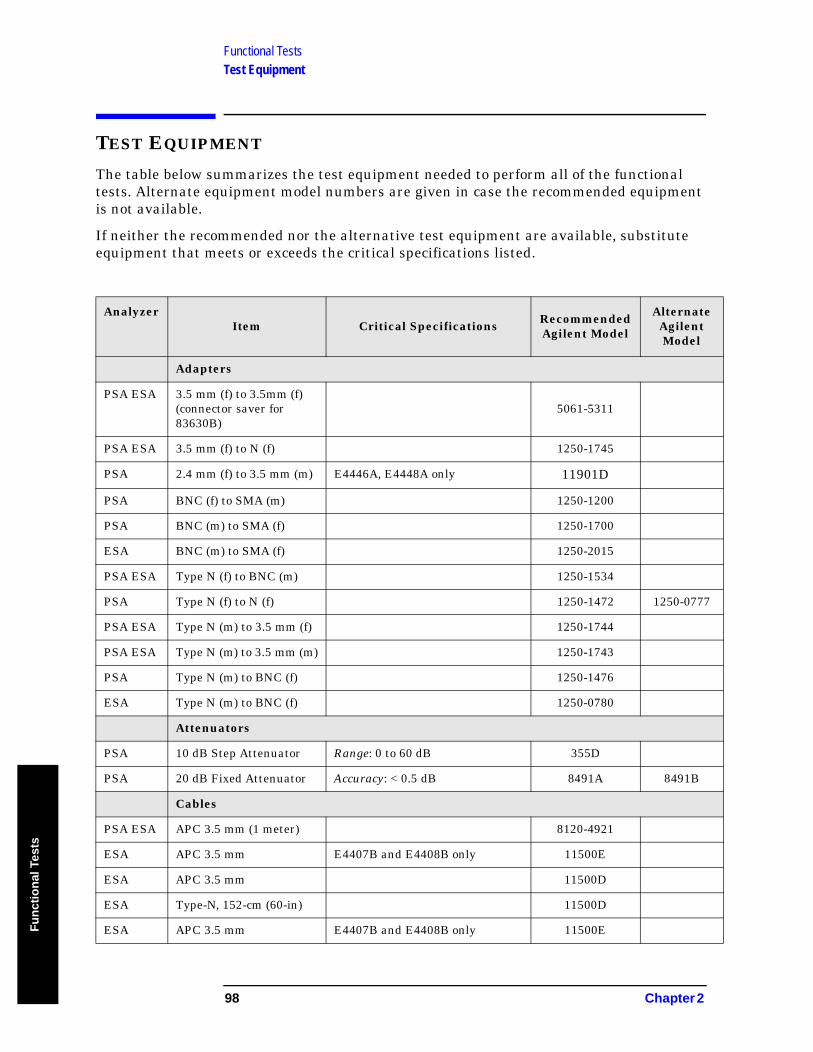
Functional TestsTest Equipment
Fu
nct
ion
al T
ests
TEST EQUIPMENT
The table below summarizes the test equipment needed to perform all of the functional tests. Alternate equipment model numbers are given in case the recommended equipment is not available.
If neither the recommended nor the alternative test equipment are available, substitute equipment that meets or exceeds the critical specifications listed.
AnalyzerItem Critical Specifications Recommended
Agilent Model
Alternate Agilent Model
Adapters
PSA ESA 3.5 mm (f) to 3.5mm (f)(connector saver for 83630B)
5061-5311
PSA ESA 3.5 mm (f) to N (f) 1250-1745
PSA 2.4 mm (f) to 3.5 mm (m) E4446A, E4448A only 11901D
PSA BNC (f) to SMA (m) 1250-1200
PSA BNC (m) to SMA (f) 1250-1700
ESA BNC (m) to SMA (f) 1250-2015
PSA ESA Type N (f) to BNC (m) 1250-1534
PSA Type N (f) to N (f) 1250-1472 1250-0777
PSA ESA Type N (m) to 3.5 mm (f) 1250-1744
PSA ESA Type N (m) to 3.5 mm (m) 1250-1743
PSA Type N (m) to BNC (f) 1250-1476
ESA Type N (m) to BNC (f) 1250-0780
Attenuators
PSA 10 dB Step Attenuator Range: 0 to 60 dB 355D
PSA 20 dB Fixed Attenuator Accuracy: < 0.5 dB 8491A 8491B
Cables
PSA ESA APC 3.5 mm (1 meter) 8120-4921
ESA APC 3.5 mm E4407B and E4408B only 11500E
ESA APC 3.5 mm 11500D
ESA Type-N, 152-cm (60-in) 11500D
ESA APC 3.5 mm E4407B and E4408B only 11500E
98 Chapter 2
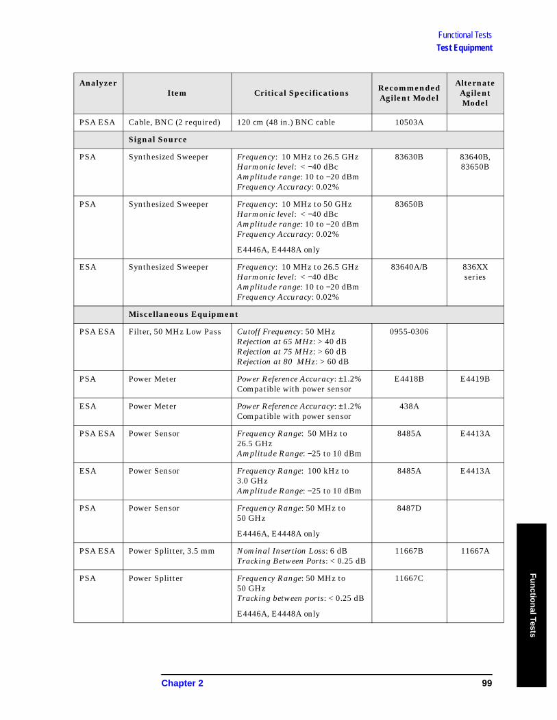
Functional TestsTest Equipment
Fu
nctio
nal Tests
PSA ESA Cable, BNC (2 required) 120 cm (48 in.) BNC cable 10503A
Signal Source
PSA Synthesized Sweeper Frequency: 10 MHz to 26.5 GHzHarmonic level: < −40 dBcAmplitude range: 10 to −20 dBmFrequency Accuracy: 0.02%
83630B 83640B, 83650B
PSA Synthesized Sweeper Frequency: 10 MHz to 50 GHzHarmonic level: < −40 dBcAmplitude range: 10 to −20 dBmFrequency Accuracy: 0.02%
E4446A, E4448A only
83650B
ESA Synthesized Sweeper Frequency: 10 MHz to 26.5 GHzHarmonic level: < −40 dBcAmplitude range: 10 to −20 dBmFrequency Accuracy: 0.02%
83640A/B 836XX series
Miscellaneous Equipment
PSA ESA Filter, 50 MHz Low Pass Cutoff Frequency: 50 MHzRejection at 65 MHz: > 40 dBRejection at 75 MHz: > 60 dBRejection at 80 MHz: > 60 dB
0955-0306
PSA Power Meter Power Reference Accuracy: ±1.2%Compatible with power sensor
E4418B E4419B
ESA Power Meter Power Reference Accuracy: ±1.2%Compatible with power sensor
438A
PSA ESA Power Sensor Frequency Range: 50 MHz to 26.5 GHzAmplitude Range: −25 to 10 dBm
8485A E4413A
ESA Power Sensor Frequency Range: 100 kHz to 3.0 GHzAmplitude Range: −25 to 10 dBm
8485A E4413A
PSA Power Sensor Frequency Range: 50 MHz to 50 GHz
E4446A, E4448A only
8487D
PSA ESA Power Splitter, 3.5 mm Nominal Insertion Loss: 6 dBTracking Between Ports: < 0.25 dB
11667B 11667A
PSA Power Splitter Frequency Range: 50 MHz to 50 GHzTracking between ports: < 0.25 dB
E4446A, E4448A only
11667C
AnalyzerItem Critical Specifications Recommended
Agilent Model
Alternate Agilent Model
Chapter 2 99
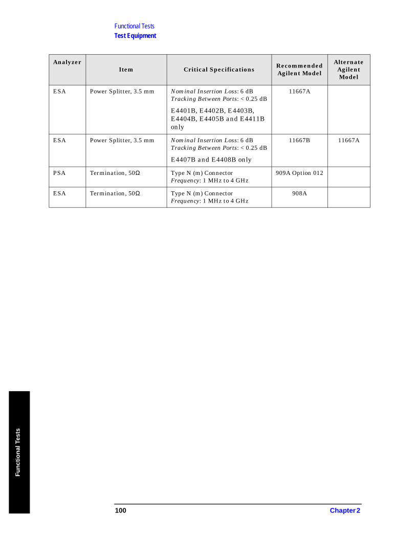
Functional TestsTest Equipment
Fu
nct
ion
al T
ests
ESA Power Splitter, 3.5 mm Nominal Insertion Loss: 6 dBTracking Between Ports: < 0.25 dB
E4401B, E4402B, E4403B, E4404B, E4405B and E4411B only
11667A
ESA Power Splitter, 3.5 mm Nominal Insertion Loss: 6 dBTracking Between Ports: < 0.25 dB
E4407B and E4408B only
11667B 11667A
PSA Termination, 50Ω Type N (m) ConnectorFrequency: 1 MHz to 4 GHz
909A Option 012
ESA Termination, 50Ω Type N (m) ConnectorFrequency: 1 MHz to 4 GHz
908A
AnalyzerItem Critical Specifications Recommended
Agilent Model
Alternate Agilent Model
100 Chapter 2

PS
A F
un
ction
al Tests
3 PSA Functional Tests
101
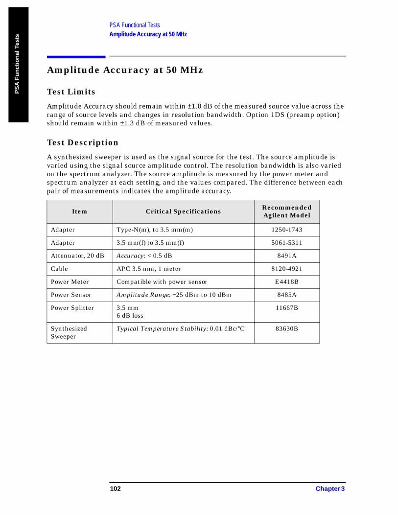
PSA Functional TestsAmplitude Accuracy at 50 MHz
PS
A F
un
ctio
nal
Tes
ts
Amplitude Accuracy at 50 MHz
Test Limits
Amplitude Accuracy should remain within ±1.0 dB of the measured source value across the range of source levels and changes in resolution bandwidth. Option 1DS (preamp option) should remain within ±1.3 dB of measured values.
Test Description
A synthesized sweeper is used as the signal source for the test. The source amplitude is varied using the signal source amplitude control. The resolution bandwidth is also varied on the spectrum analyzer. The source amplitude is measured by the power meter and spectrum analyzer at each setting, and the values compared. The difference between each pair of measurements indicates the amplitude accuracy.
Item Critical Specifications Recommended Agilent Model
Adapter Type-N(m), to 3.5 mm(m) 1250-1743
Adapter 3.5 mm(f) to 3.5 mm(f) 5061-5311
Attenuator, 20 dB Accuracy: < 0.5 dB 8491A
Cable APC 3.5 mm, 1 meter 8120-4921
Power Meter Compatible with power sensor E4418B
Power Sensor Amplitude Range: −25 dBm to 10 dBm 8485A
Power Splitter 3.5 mm6 dB loss
11667B
Synthesized Sweeper
Typical Temperature Stability: 0.01 dBc/°C 83630B
102 Chapter 3
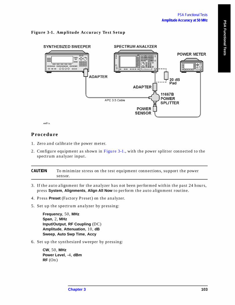
PSA Functional TestsAmplitude Accuracy at 50 MHz P
SA
Fu
nctio
nal Tests
Figure 3-1. Amplitude Accuracy Test Setup
Procedure
1. Zero and calibrate the power meter.
2. Configure equipment as shown in Figure 3-1., with the power splitter connected to the spectrum analyzer input.
CAUTION To minimize stress on the test equipment connections, support the power sensor.
3. If the auto alignment for the analyzer has not been performed within the past 24 hours, press System, Alignments, Align All Now to perform the auto alignment routine.
4. Press Preset (Factory Preset) on the analyzer.
5. Set up the spectrum analyzer by pressing:
Frequency, 50, MHzSpan, 2, MHzInput/Output, RF Coupling (DC)Amplitude, Attenuation, 10, dBSweep, Auto Swp Time, Accy
6. Set up the synthesized sweeper by pressing:
CW, 50, MHzPower Level, -4, dBmRF (On)
Chapter 3 103
PSA Functional TestsAmplitude Accuracy at 50 MHz
PS
A F
un
ctio
nal
Tes
ts
7. On the spectrum analyzer, press:
BW/Avg, Average (On)20, Enter
8. Perform the following steps for each row listed in Table 3-1:
a. Set the synthesized sweeper amplitude to the value listed in the Nominal Source Amplitude column in Table 3-1.
b. Set the Attenuation and Span as listed in each row of the table.
c. Record the source amplitude, as measured by the power meter, in the Power Meter Amplitude column of Table 3-1.
d. On the spectrum analyzer, press Restart, Peak Search.
e. Wait for the spectrum analyzer to finish averaging.
f. Record the signal amplitude, as measured by the analyzer in the Measured Amplitude column of Table 3-1.
g. Calculate the signal amplitude accuracy error using the following equation, and record the results under the Amplitude Accuracy Error column:
Amplitude Accuracy Error = Meas_amp − Power_meter
104 Chapter 3
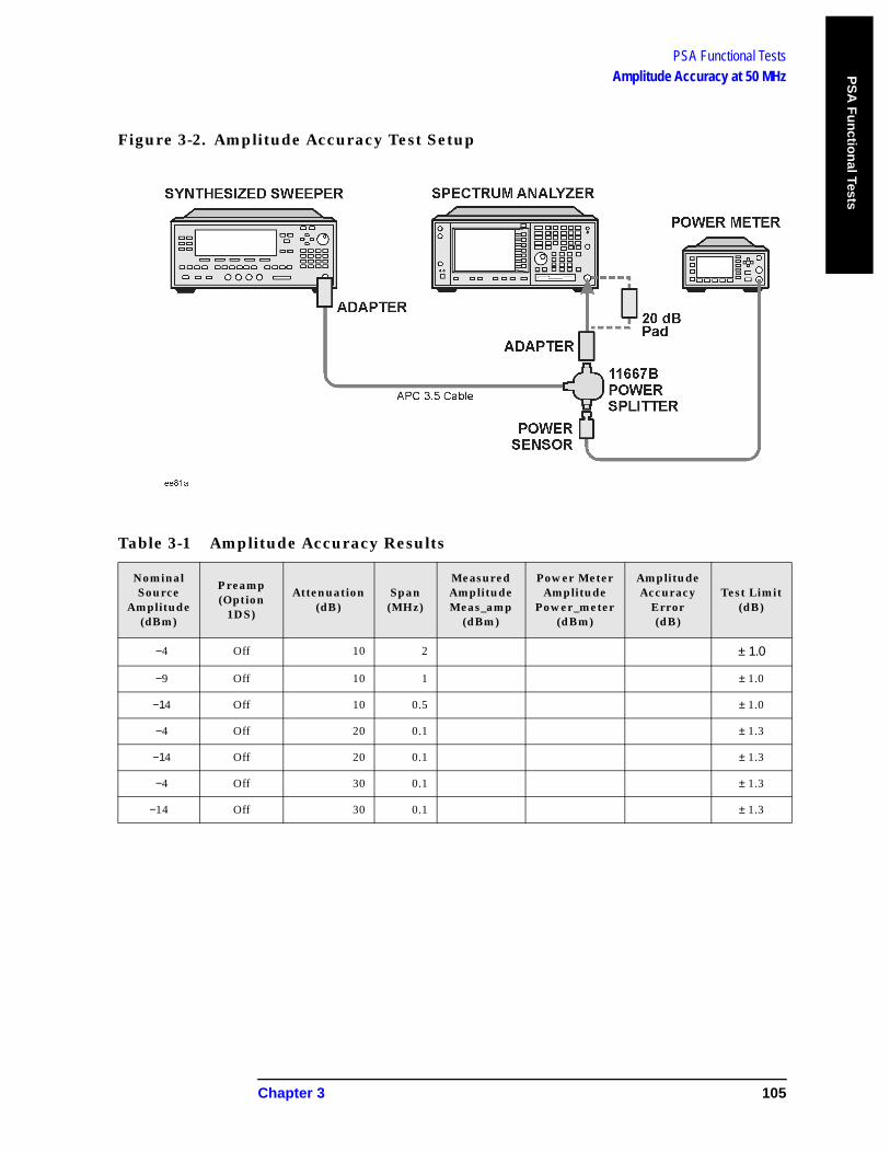
PSA Functional TestsAmplitude Accuracy at 50 MHz P
SA
Fu
nctio
nal Tests
Figure 3-2. Amplitude Accuracy Test Setup
Table 3-1 Amplitude Accuracy Results
NominalSource
Amplitude(dBm)
Preamp(Option
1DS)
Attenuation (dB)
Span (MHz)
MeasuredAmplitudeMeas_amp
(dBm)
Power MeterAmplitude
Power_meter(dBm)
AmplitudeAccuracy
Error(dB)
Test Limit(dB)
−4 Off 10 2 ± 1.0
−9 Off 10 1 ± 1.0
−14 Off 10 0.5 ± 1.0
−4 Off 20 0.1 ± 1.3
−14 Off 20 0.1 ± 1.3
−4 Off 30 0.1 ± 1.3
−14 Off 30 0.1 ± 1.3
Chapter 3 105
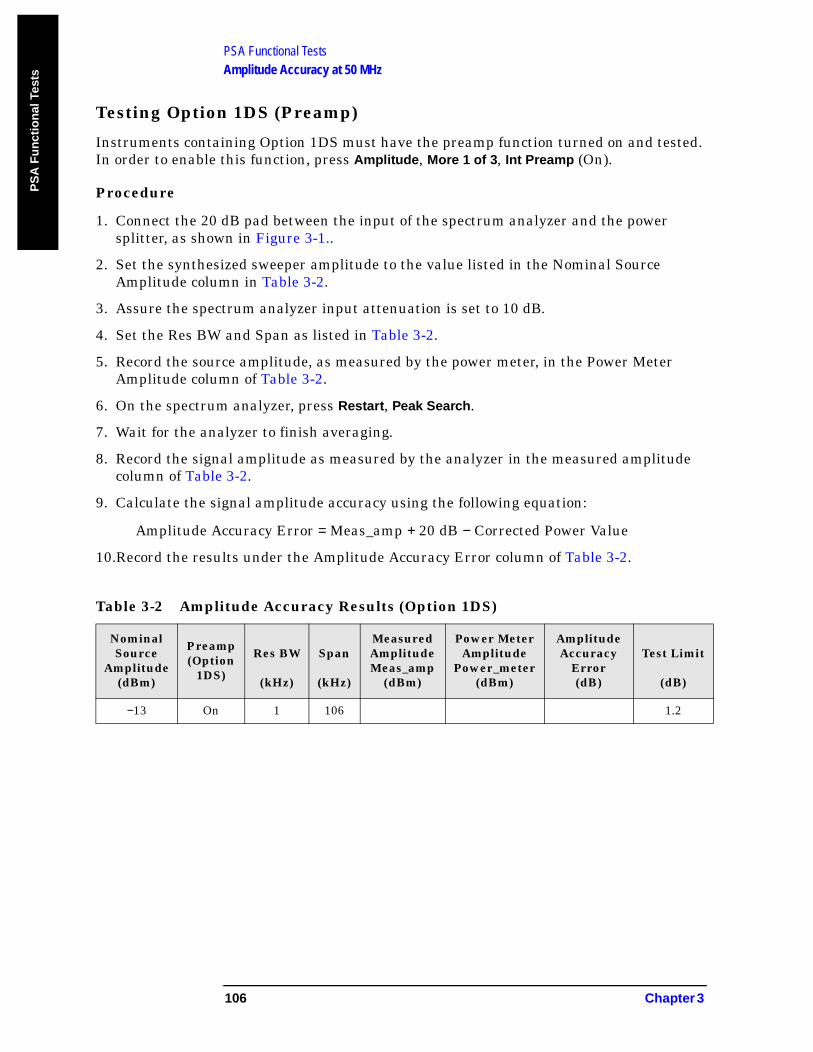
PSA Functional TestsAmplitude Accuracy at 50 MHz
PS
A F
un
ctio
nal
Tes
ts
Testing Option 1DS (Preamp)
Instruments containing Option 1DS must have the preamp function turned on and tested. In order to enable this function, press Amplitude, More 1 of 3, Int Preamp (On).
Procedure
1. Connect the 20 dB pad between the input of the spectrum analyzer and the power splitter, as shown in Figure 3-1..
2. Set the synthesized sweeper amplitude to the value listed in the Nominal Source Amplitude column in Table 3-2.
3. Assure the spectrum analyzer input attenuation is set to 10 dB.
4. Set the Res BW and Span as listed in Table 3-2.
5. Record the source amplitude, as measured by the power meter, in the Power Meter Amplitude column of Table 3-2.
6. On the spectrum analyzer, press Restart, Peak Search.
7. Wait for the analyzer to finish averaging.
8. Record the signal amplitude as measured by the analyzer in the measured amplitude column of Table 3-2.
9. Calculate the signal amplitude accuracy using the following equation:
Amplitude Accuracy Error = Meas_amp + 20 dB − Corrected Power Value
10.Record the results under the Amplitude Accuracy Error column of Table 3-2.
Table 3-2 Amplitude Accuracy Results (Option 1DS)
NominalSource
Amplitude(dBm)
Preamp(Option
1DS)
Res BW
(kHz)
Span
(kHz)
MeasuredAmplitudeMeas_amp
(dBm)
Power MeterAmplitude
Power_meter(dBm)
AmplitudeAccuracy
Error(dB)
Test Limit
(dB)
−13 On 1 106 1.2
106 Chapter 3
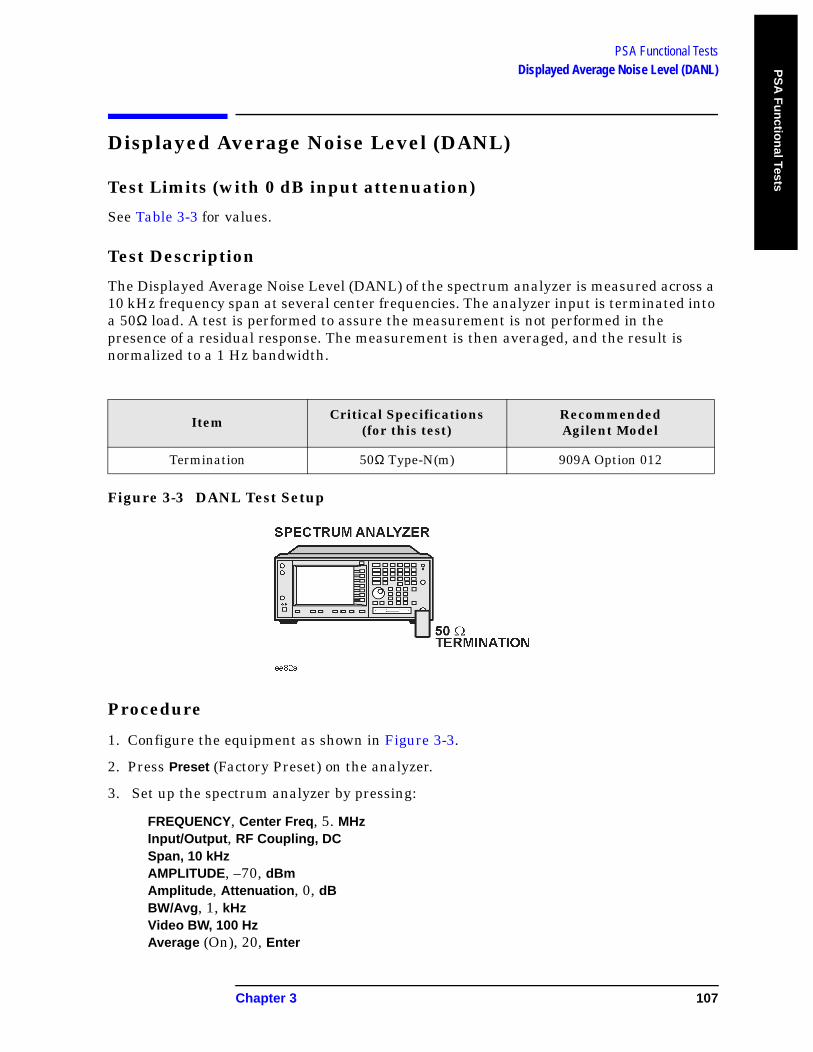
PSA Functional TestsDisplayed Average Noise Level (DANL) P
SA
Fu
nctio
nal Tests
Displayed Average Noise Level (DANL)
Test Limits (with 0 dB input attenuation)
See Table 3-3 for values.
Test Description
The Displayed Average Noise Level (DANL) of the spectrum analyzer is measured across a 10 kHz frequency span at several center frequencies. The analyzer input is terminated into a 50Ω load. A test is performed to assure the measurement is not performed in the presence of a residual response. The measurement is then averaged, and the result is normalized to a 1 Hz bandwidth.
Figure 3-3 DANL Test Setup
Procedure
1. Configure the equipment as shown in Figure 3-3.
2. Press Preset (Factory Preset) on the analyzer.
3. Set up the spectrum analyzer by pressing:
FREQUENCY, Center Freq, 5. MHzInput/Output, RF Coupling, DCSpan, 10 kHzAMPLITUDE, –70, dBmAmplitude, Attenuation, 0, dBBW/Avg, 1, kHzVideo BW, 100 HzAverage (On), 20, Enter
Item Critical Specifications(for this test)
RecommendedAgilent Model
Termination 50Ω Type-N(m) 909A Option 012
Chapter 3 107
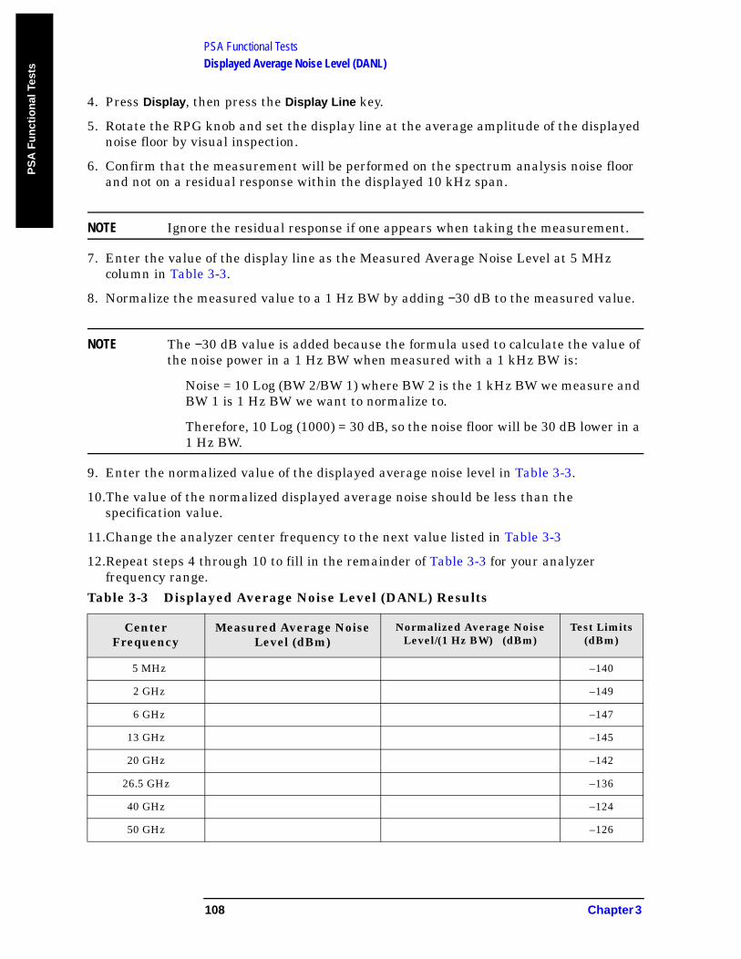
PSA Functional TestsDisplayed Average Noise Level (DANL)
PS
A F
un
ctio
nal
Tes
ts
4. Press Display, then press the Display Line key.
5. Rotate the RPG knob and set the display line at the average amplitude of the displayed noise floor by visual inspection.
6. Confirm that the measurement will be performed on the spectrum analysis noise floor and not on a residual response within the displayed 10 kHz span.
NOTE Ignore the residual response if one appears when taking the measurement.
7. Enter the value of the display line as the Measured Average Noise Level at 5 MHz column in Table 3-3.
8. Normalize the measured value to a 1 Hz BW by adding −30 dB to the measured value.
NOTE The −30 dB value is added because the formula used to calculate the value of the noise power in a 1 Hz BW when measured with a 1 kHz BW is:
Noise = 10 Log (BW 2/BW 1) where BW 2 is the 1 kHz BW we measure and BW 1 is 1 Hz BW we want to normalize to.
Therefore, 10 Log (1000) = 30 dB, so the noise floor will be 30 dB lower in a 1 Hz BW.
9. Enter the normalized value of the displayed average noise level in Table 3-3.
10.The value of the normalized displayed average noise should be less than the specification value.
11.Change the analyzer center frequency to the next value listed in Table 3-3
12.Repeat steps 4 through 10 to fill in the remainder of Table 3-3 for your analyzer frequency range.
Table 3-3 Displayed Average Noise Level (DANL) Results
Center Frequency
Measured Average Noise Level (dBm)
Normalized Average Noise Level/(1 Hz BW) (dBm)
Test Limits (dBm)
5 MHz –140
2 GHz –149
6 GHz –147
13 GHz –145
20 GHz –142
26.5 GHz –136
40 GHz –124
50 GHz –126
108 Chapter 3
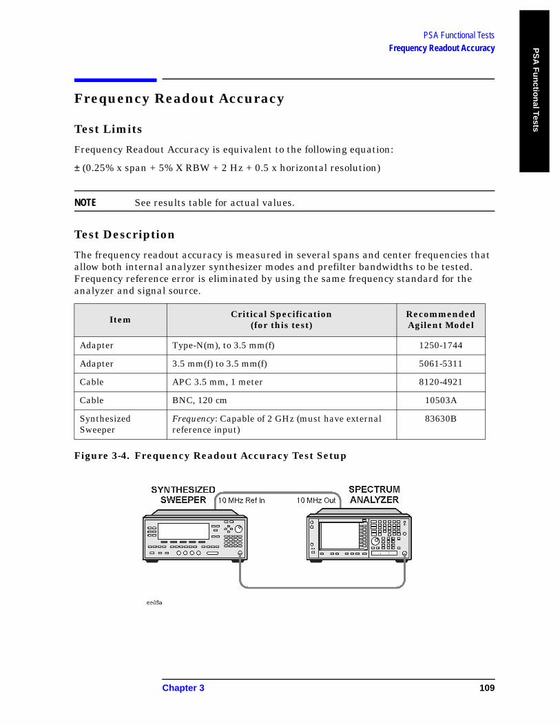
PSA Functional TestsFrequency Readout Accuracy P
SA
Fu
nctio
nal Tests
Frequency Readout Accuracy
Test Limits
Frequency Readout Accuracy is equivalent to the following equation:
± (0.25% x span + 5% X RBW + 2 Hz + 0.5 x horizontal resolution)
NOTE See results table for actual values.
Test Description
The frequency readout accuracy is measured in several spans and center frequencies that allow both internal analyzer synthesizer modes and prefilter bandwidths to be tested. Frequency reference error is eliminated by using the same frequency standard for the analyzer and signal source.
Figure 3-4. Frequency Readout Accuracy Test Setup
Item Critical Specification(for this test)
Recommended Agilent Model
Adapter Type-N(m), to 3.5 mm(f) 1250-1744
Adapter 3.5 mm(f) to 3.5 mm(f) 5061-5311
Cable APC 3.5 mm, 1 meter 8120-4921
Cable BNC, 120 cm 10503A
Synthesized Sweeper
Frequency: Capable of 2 GHz (must have external reference input)
83630B
Chapter 3 109
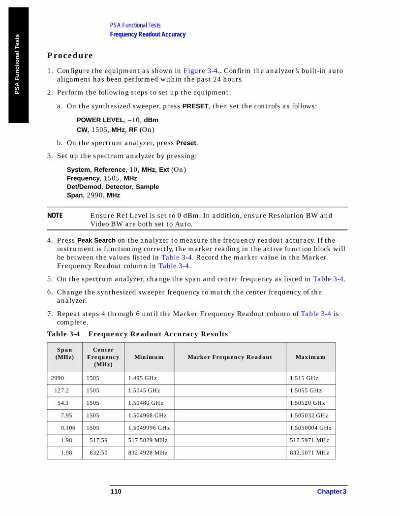
PSA Functional TestsFrequency Readout Accuracy
PS
A F
un
ctio
nal
Tes
ts
Procedure
1. Configure the equipment as shown in Figure 3-4.. Confirm the analyzer’s built-in auto alignment has been performed within the past 24 hours.
2. Perform the following steps to set up the equipment:
a. On the synthesized sweeper, press PRESET, then set the controls as follows:
POWER LEVEL, –10, dBm
CW, 1505, MHz, RF (On)
b. On the spectrum analyzer, press Preset.
3. Set up the spectrum analyzer by pressing:
System, Reference, 10, MHz, Ext (On)Frequency, 1505, MHzDet/Demod, Detector, SampleSpan, 2990, MHz
NOTE Ensure Ref Level is set to 0 dBm. In addition, ensure Resolution BW and Video BW are both set to Auto.
4. Press Peak Search on the analyzer to measure the frequency readout accuracy. If the instrument is functioning correctly, the marker reading in the active function block will be between the values listed in Table 3-4. Record the marker value in the Marker Frequency Readout column in Table 3-4.
5. On the spectrum analyzer, change the span and center frequency as listed in Table 3-4.
6. Change the synthesized sweeper frequency to match the center frequency of the analyzer.
7. Repeat steps 4 through 6 until the Marker Frequency Readout column of Table 3-4 is complete.
Table 3-4 Frequency Readout Accuracy Results
Span(MHz)
CenterFrequency
(MHz)Minimum Marker Frequency Readout Maximum
2990 1505 1.495 GHz 1.515 GHz
127.2 1505 1.5045 GHz 1.5055 GHz
54.1 1505 1.50480 GHz 1.50520 GHz
7.95 1505 1.504968 GHz 1.505032 GHz
0.106 1505 1.5049996 GHz 1.5050004 GHz
1.98 517.59 517.5829 MHz 517.5971 MHz
1.98 832.50 832.4928 MHz 832.5071 MHz
110 Chapter 3
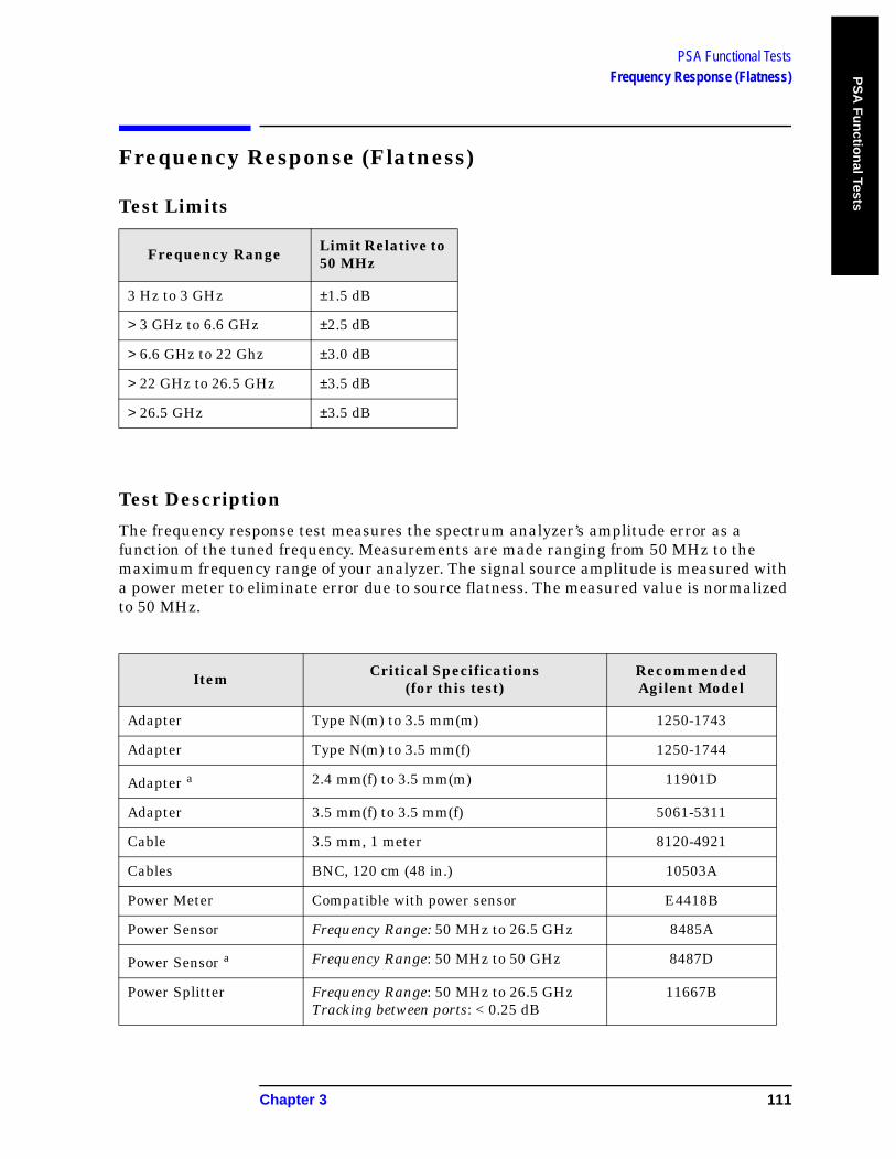
PSA Functional TestsFrequency Response (Flatness) P
SA
Fu
nctio
nal Tests
Frequency Response (Flatness)
Test Limits
Test Description
The frequency response test measures the spectrum analyzer’s amplitude error as a function of the tuned frequency. Measurements are made ranging from 50 MHz to the maximum frequency range of your analyzer. The signal source amplitude is measured with a power meter to eliminate error due to source flatness. The measured value is normalized to 50 MHz.
Frequency Range Limit Relative to 50 MHz
3 Hz to 3 GHz ±1.5 dB
> 3 GHz to 6.6 GHz ±2.5 dB
> 6.6 GHz to 22 Ghz ±3.0 dB
> 22 GHz to 26.5 GHz ±3.5 dB
> 26.5 GHz ±3.5 dB
Item Critical Specifications(for this test)
Recommended Agilent Model
Adapter Type N(m) to 3.5 mm(m) 1250-1743
Adapter Type N(m) to 3.5 mm(f) 1250-1744
Adapter a 2.4 mm(f) to 3.5 mm(m) 11901D
Adapter 3.5 mm(f) to 3.5 mm(f) 5061-5311
Cable 3.5 mm, 1 meter 8120-4921
Cables BNC, 120 cm (48 in.) 10503A
Power Meter Compatible with power sensor E4418B
Power Sensor Frequency Range: 50 MHz to 26.5 GHz 8485A
Power Sensor a Frequency Range: 50 MHz to 50 GHz 8487D
Power Splitter Frequency Range: 50 MHz to 26.5 GHz Tracking between ports: < 0.25 dB
11667B
Chapter 3 111
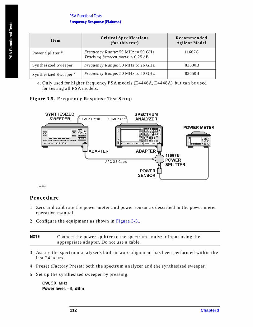
PSA Functional TestsFrequency Response (Flatness)
PS
A F
un
ctio
nal
Tes
ts
Figure 3-5. Frequency Response Test Setup
Procedure
1. Zero and calibrate the power meter and power sensor as described in the power meter operation manual.
2. Configure the equipment as shown in Figure 3-5..
NOTE Connect the power splitter to the spectrum analyzer input using the appropriate adapter. Do not use a cable.
3. Assure the spectrum analyzer’s built-in auto alignment has been performed within the last 24 hours.
4. Preset (Factory Preset) both the spectrum analyzer and the synthesized sweeper.
5. Set up the synthesized sweeper by pressing:
CW, 50, MHzPower level, –8, dBm
Power Splitter a Frequency Range: 50 MHz to 50 GHz Tracking between ports: < 0.25 dB
11667C
Synthesized Sweeper Frequency Range: 50 MHz to 26 GHz 83630B
Synthesized Sweeper a Frequency Range: 50 MHz to 50 GHz 83650B
a. Only used for higher frequency PSA models (E4446A, E4448A), but can be used for testing all PSA models.
Item Critical Specifications(for this test)
Recommended Agilent Model
112 Chapter 3
PSA Functional TestsFrequency Response (Flatness) P
SA
Fu
nctio
nal Tests
6. Set up the spectrum analyzer by pressing:
Frequency, 50, MHzSpan, 50, kHzAmplitude (ref level), –10, dBmBW/Avg, Average (On), 10, Enter
7. Adjust the synthesized sweeper output power for a power meter display of –14 dBm ±0.1 dB.
NOTE The power level of the synthesized sweeper remains unchanged for the duration of the test.
8. Press the Peak Search key on the signal analyzer to position the marker on the peak of the signal.
9. Refer to Table 3-5, “Frequency Response (Flatness) Results.” Enter the amplitude of the signal displayed on the spectrum analyzer into the MeasAmp column of Table 3-5.
10.Enter the power meter reading into the PowerMeter column of Table 3-5.
11.Tune the synthesized sweeper and spectrum analyzer to the next frequency listed in Table 3-5.
12.Enter the power sensor calibration factor into the power meter.
13.For frequencies 3 GHz and above, press Amplitude, then Presel Center to center the preselector filter for an optimum amplitude measurement.
14.Repeat steps 8-13 and complete the remainder of Table 3-5 for the frequency range of your analyzer.
15.Compute the measurement error (MeasError = MeasAmp − PowerMeter).
16.Compute the flatness error normalized to 50 MHz:(MeasError − MeasError @ 50 MHz)
17.Enter the computed flatness error value into the FlatNorm column of Table 3-5.
18.Compare the value of FlatNorm to the test limit.
Chapter 3 113

PSA Functional TestsFrequency Response (Flatness)
PS
A F
un
ctio
nal
Tes
ts
Table 3-5 Frequency Response (Flatness) Results
CenterFrequency
Analyzer Amplitude
Measamp
Power Meter Measurement
Powermeter
Meas Error
Measerror
Flatness Normalizedto 50 MHzFlatNorm
Flatness ErrorTest Limits
(dB)
50 MHz 0 Ref
1 GHz ±1.5
2 GHz ±1.5
3 GHz ±1.5
3.5 GHz ±2.5
5 GHz ±2.5
6 GHz ±2.5
7 GHz ±3.0
10 GHz ±3.0
13 GHz ±3.0
14 GHz ±3.0
16 GHz ±3.0
22 GHz ±3.0
23 GHz ±3.5
25 GHz ±3.5
26.5 GHz ±3.5
28 GHz ±3.5
31.5 GHz ±3.5
42 GHz ±3.5
48 GHz ±3.5
114 Chapter 3
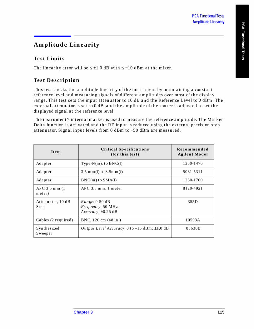
PSA Functional TestsAmplitude Linearity P
SA
Fu
nctio
nal Tests
Amplitude Linearity
Test Limits
The linearity error will be ≤ ±1.0 dB with ≤ −10 dBm at the mixer.
Test Description
This test checks the amplitude linearity of the instrument by maintaining a constant reference level and measuring signals of different amplitudes over most of the display range. This test sets the input attenuator to 10 dB and the Reference Level to 0 dBm. The external attenuator is set to 0 dB, and the amplitude of the source is adjusted to set the displayed signal at the reference level.
The instrument’s internal marker is used to measure the reference amplitude. The Marker Delta function is activated and the RF input is reduced using the external precision step attenuator. Signal input levels from 0 dBm to −50 dBm are measured.
Item Critical Specifications(for this test)
Recommended Agilent Model
Adapter Type-N(m), to BNC(f) 1250-1476
Adapter 3.5 mm(f) to 3.5mm(f) 5061-5311
Adapter BNC(m) to SMA(f) 1250-1700
APC 3.5 mm (1 meter)
APC 3.5 mm, 1 meter 8120-4921
Attenuator, 10 dB Step
Range: 0-50 dBFrequency: 50 MHzAccuracy: ±0.25 dB
355D
Cables (2 required) BNC, 120 cm (48 in.) 10503A
Synthesized Sweeper
Output Level Accuracy: 0 to –15 dBm: ±1.0 dB 83630B
Chapter 3 115
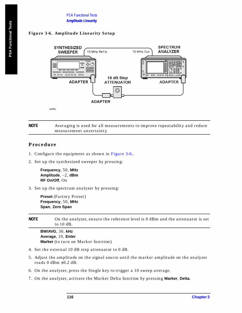
PSA Functional TestsAmplitude Linearity
PS
A F
un
ctio
nal
Tes
ts
Figure 3-6. Amplitude Linearity Setup
NOTE Averaging is used for all measurements to improve repeatability and reduce measurement uncertainty.
Procedure
1. Configure the equipment as shown in Figure 3-6..
2. Set up the synthesized sweeper by pressing:
Frequency, 50, MHzAmplitude, –2, dBmRF On/Off, On
3. Set up the spectrum analyzer by pressing:
Preset (Factory Preset)Frequency, 50, MHzSpan, Zero Span
NOTE On the analyzer, ensure the reference level is 0 dBm and the attenuator is set to 10 dB.
BW/AVG, 30, kHzAverage, 10, EnterMarker (to turn on Marker function)
4. Set the external 10 dB step attenuator to 0 dB.
5. Adjust the amplitude on the signal source until the marker amplitude on the analyzer reads 0 dBm ±0.2 dB.
6. On the analyzer, press the Single key to trigger a 10 sweep average.
7. On the analyzer, activate the Marker Delta function by pressing Marker, Delta.
116 Chapter 3
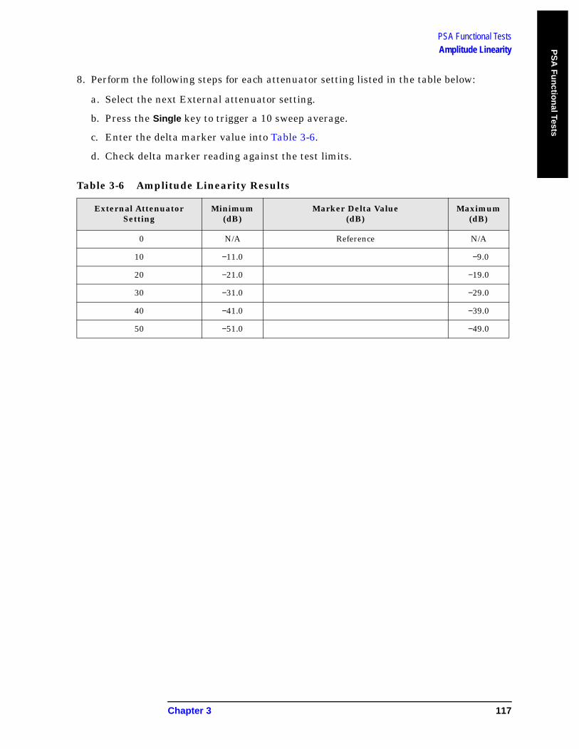
PSA Functional TestsAmplitude Linearity P
SA
Fu
nctio
nal Tests
8. Perform the following steps for each attenuator setting listed in the table below:
a. Select the next External attenuator setting.
b. Press the Single key to trigger a 10 sweep average.
c. Enter the delta marker value into Table 3-6.
d. Check delta marker reading against the test limits.
Table 3-6 Amplitude Linearity Results
External Attenuator Setting
Minimum(dB)
Marker Delta Value (dB)
Maximum (dB)
0 N/A Reference N/A
10 −11.0 −9.0
20 −21.0 −19.0
30 −31.0 −29.0
40 −41.0 −39.0
50 −51.0 −49.0
Chapter 3 117
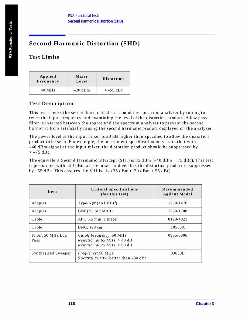
PSA Functional TestsSecond Harmonic Distortion (SHD)
PS
A F
un
ctio
nal
Tes
ts
Second Harmonic Distortion (SHD)
Test Limits
Test Description
This test checks the second harmonic distortion of the spectrum analyzer by tuning to twice the input frequency and examining the level of the distortion product. A low pass filter is inserted between the source and the spectrum analyzer to prevent the second harmonic from artificially raising the second harmonic product displayed on the analyzer.
The power level at the input mixer is 20 dB higher than specified to allow the distortion product to be seen. For example, the instrument specification may state that with a –40 dBm signal at the input mixer, the distortion product should be suppressed by > –75 dBc.
The equivalent Second Harmonic Intercept (SHI) is 35 dBm (–40 dBm + 75 dBc). This test is performed with –20 dBm at the mixer and verifies the distortion product is suppressed by –55 dBc. This ensures the SHI is also 35 dBm (–20 dBm + 55 dBc).
Applied Frequency
Mixer Level Distortion
40 MHz –20 dBm < –55 dBc
Item Critical Specifications(for this test)
Recommended Agilent Model
Adapter Type-N(m) to BNC(f) 1250-1476
Adapter BNC(m) to SMA(f) 1250-1700
Cable APC 3.5 mm, 1 meter 8120-4921
Cable BNC, 120 cm 10503A
Filter, 50 MHz Low Pass
Cutoff Frequency: 50 MHzRejection at 65 MHz: > 40 dBRejection at 75 MHz: > 60 dB
0955-0306
Synthesized Sweeper Frequency: 50 MHzSpectral Purity: Better than –30 dBc
83630B
118 Chapter 3
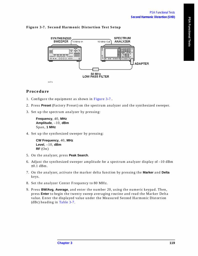
PSA Functional TestsSecond Harmonic Distortion (SHD) P
SA
Fu
nctio
nal Tests
Figure 3-7. Second Harmonic Distortion Test Setup
Procedure
1. Configure the equipment as shown in Figure 3-7..
2. Press Preset (Factory Preset) on the spectrum analyzer and the synthesized sweeper.
3. Set up the spectrum analyzer by pressing:
Frequency, 40, MHzAmplitude, –10, dBmSpan, 1 MHz
4. Set up the synthesized sweeper by pressing:
CW Frequency, 40, MHzLevel, –10, dBmRF (On)
5. On the analyzer, press Peak Search.
6. Adjust the synthesized sweeper amplitude for a spectrum analyzer display of –10 dBm ±0.1 dBm.
7. On the analyzer, activate the marker delta function by pressing the Marker and Delta keys.
8. Set the analyzer Center Frequency to 80 MHz.
9. Press BW/Avg, Average, and enter the number 20, using the numeric keypad. Then, press Enter to begin the twenty sweep averaging routine and read the Marker Delta value. Enter the displayed value under the Measured Second Harmonic Distortion (dBc) heading in Table 3-7.
Chapter 3 119

PSA Functional TestsSecond Harmonic Distortion (SHD)
PS
A F
un
ctio
nal
Tes
ts
Table 3-7 Second Harmonic Distortion Results
Applied Frequency
(MHz)
Measured Second Harmonic Distortion (dBc)
Specification (dBc)
40 <−55
120 Chapter 3
ES
A F
un
ction
al Tests
4 ESA Functional Tests
121
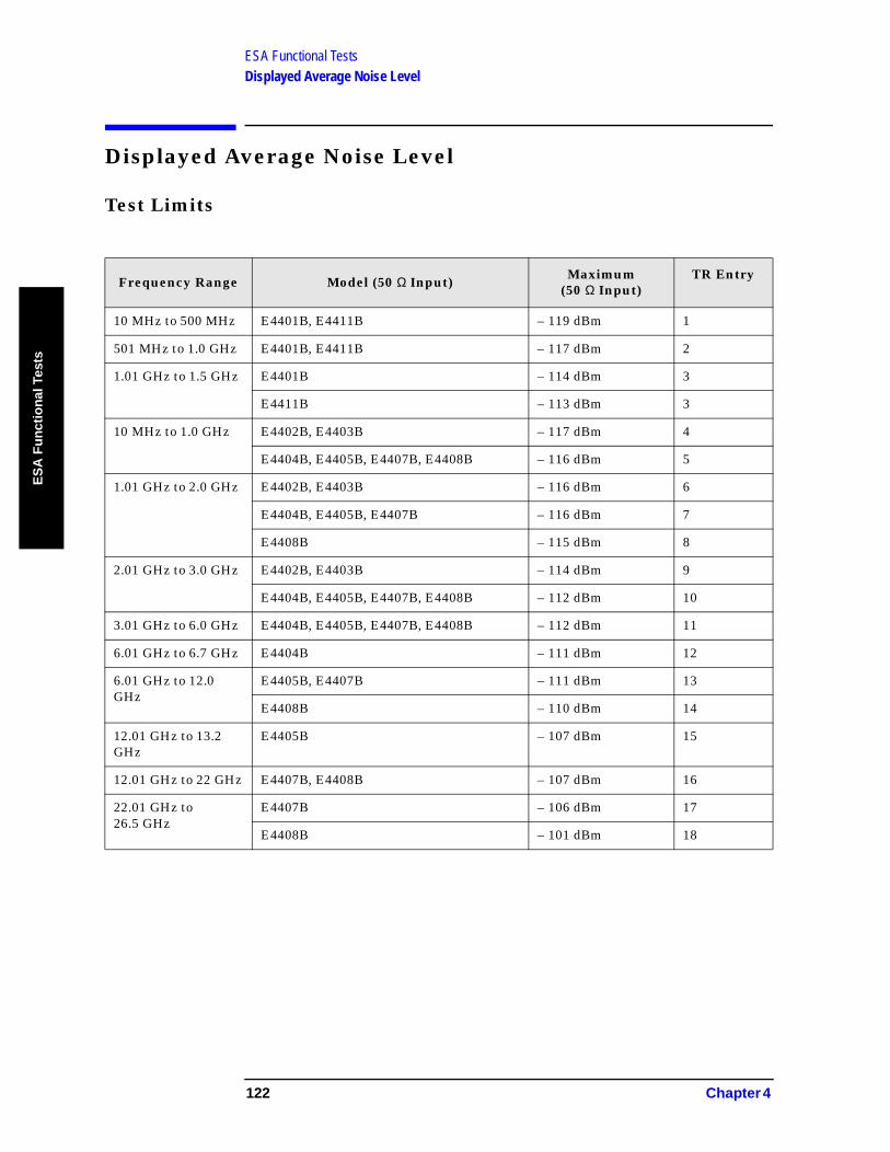
ESA Functional TestsDisplayed Average Noise Level
ES
A F
un
ctio
nal
Tes
ts
Displayed Average Noise Level
Test Limits
Frequency Range Model (50 Ω Input) Maximum(50 Ω Input)
TR Entry
10 MHz to 500 MHz E4401B, E4411B – 119 dBm 1
501 MHz to 1.0 GHz E4401B, E4411B – 117 dBm 2
1.01 GHz to 1.5 GHz E4401B – 114 dBm 3
E4411B – 113 dBm 3
10 MHz to 1.0 GHz E4402B, E4403B – 117 dBm 4
E4404B, E4405B, E4407B, E4408B – 116 dBm 5
1.01 GHz to 2.0 GHz E4402B, E4403B – 116 dBm 6
E4404B, E4405B, E4407B – 116 dBm 7
E4408B – 115 dBm 8
2.01 GHz to 3.0 GHz E4402B, E4403B – 114 dBm 9
E4404B, E4405B, E4407B, E4408B – 112 dBm 10
3.01 GHz to 6.0 GHz E4404B, E4405B, E4407B, E4408B – 112 dBm 11
6.01 GHz to 6.7 GHz E4404B – 111 dBm 12
6.01 GHz to 12.0 GHz
E4405B, E4407B – 111 dBm 13
E4408B – 110 dBm 14
12.01 GHz to 13.2 GHz
E4405B – 107 dBm 15
12.01 GHz to 22 GHz E4407B, E4408B – 107 dBm 16
22.01 GHz to 26.5 GHz
E4407B – 106 dBm 17
E4408B – 101 dBm 18
122 Chapter 4
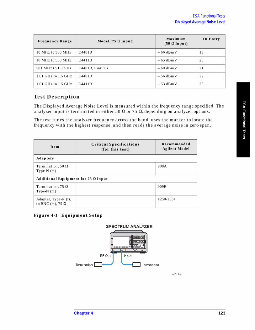
ESA Functional TestsDisplayed Average Noise Level
ES
A F
un
ction
al Tests
Test Description
The Displayed Average Noise Level is measured within the frequency range specified. The analyzer input is terminated in either 50 Ω or 75 Ω, depending on analyzer options.
The test tunes the analyzer frequency across the band, uses the marker to locate the frequency with the highest response, and then reads the average noise in zero span.
Figure 4-1 Equipment Setup
Frequency Range Model (75 Ω Input) Maximum(50 Ω Input)
TR Entry
10 MHz to 500 MHz E4401B – 66 dBmV 19
10 MHz to 500 MHz E4411B – 65 dBmV 20
501 MHz to 1.0 GHz E4401B, E4411B – 60 dBmV 21
1.01 GHz to 1.5 GHz E4401B – 56 dBmV 22
1.01 GHz to 1.5 GHz E4411B – 53 dBmV 23
ItemCritical Specifications
(for this test)Recommended Agilent Model
Adapters
Termination, 50 Ω Type-N (m)
908A
Additional Equipment for 75 Ω Input
Termination, 75 Ω Type-N (m)
909E
Adapter, Type-N (f), to BNC (m), 75 Ω
1250-1534
Chapter 4 123
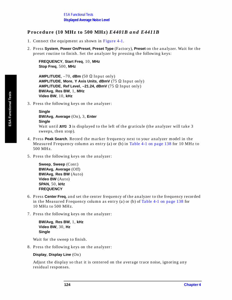
ESA Functional TestsDisplayed Average Noise Level
ES
A F
un
ctio
nal
Tes
ts
Procedure (10 MHz to 500 MHz) E4401B and E4411B
1. Connect the equipment as shown in Figure 4-1.
2. Press System, Power On/Preset, Preset Type (Factory), Preset on the analyzer. Wait for the preset routine to finish. Set the analyzer by pressing the following keys:
FREQUENCY, Start Freq, 10, MHzStop Freq, 500, MHz
AMPLITUDE, –70, dBm (50 Ω Input only)AMPLITUDE, More, Y Axis Units, dBmV (75 Ω Input only)AMPLITUDE, Ref Level, –21.24, dBmV (75 Ω Input only)BW/Avg, Res BW, 1, MHzVideo BW, 10, kHz
3. Press the following keys on the analyzer:
SingleBW/Avg, Average (On), 3, EnterSingleWait until AVG 3 is displayed to the left of the graticule (the analyzer will take 3 sweeps, then stop).
4. Press Peak Search. Record the marker frequency next to your analyzer model in the Measured Frequency column as entry (a) or (b) in Table 4-1 on page 138 for 10 MHz to 500 MHz.
5. Press the following keys on the analyzer:
Sweep, Sweep (Cont)BW/Avg, Average (Off)BW/Avg, Res BW (Auto)Video BW (Auto)SPAN, 50, kHzFREQUENCY
6. Press Center Freq, and set the center frequency of the analyzer to the frequency recorded in the Measured Frequency column as entry (a) or (b) of Table 4-1 on page 138 for 10 MHz to 500 MHz.
7. Press the following keys on the analyzer:
BW/Avg, Res BW, 1, kHzVideo BW, 30, HzSingle
Wait for the sweep to finish.
8. Press the following keys on the analyzer:
Display, Display Line (On)
Adjust the display so that it is centered on the average trace noise, ignoring any residual responses.
124 Chapter 4
ESA Functional TestsDisplayed Average Noise Level
ES
A F
un
ction
al Tests
9. Record the display line amplitude setting as TR Entry 1 (TR Entry 19 or 20 for a 75 Ω Input) in Table 4-1 on page 138. The Average Noise Level should be less than the Maximum for the appropriate input impedance.
Procedure (501 MHz to 1.0 GHz) E4401B and E4411B
1. Press the following keys on the analyzer:
Sweep, Sweep (Cont)FREQUENCY, Start Freq, 501, MHzStop Freq, 1.0, GHzBW/Avg, Res BW, 1, MHzVideo BW, 10, kHz
2. Press the following keys on the analyzer:
SingleBW/Avg, Average (On), 3, EnterSingle
Wait until AVG 3 is displayed to the left of the graticule (the analyzer will take 3 sweeps, then stop).
3. Press Peak Search, and record the marker frequency next to your analyzer model in the Measured Frequency column as entry (c) in Table 4-1 on page 138 for 501 MHz to 1.0 GHz.
4. Press the following keys on the analyzer:
Sweep, Sweep (Cont)BW/Avg, Average (Off)BW/Avg, Res BW (Auto)Video BW (Auto)SPAN, 50, kHzFREQUENCY
5. Press Center Freq. Set the center frequency of the analyzer to the frequency recorded in the Measured Frequency column as entry (c) in Table 4-1 on page 138 for 501 MHz to 1.0 GHz.
6. Press the following keys on the analyzer:
BW/Avg, Res BW, 1, kHzVideo BW, 30, HzSingle
Wait for the sweep to finish.
7. Press the following keys on the analyzer:
Display, Display Line (On)
Adjust the display line so that it is centered on the average trace noise, ignoring any
Chapter 4 125
ESA Functional TestsDisplayed Average Noise Level
ES
A F
un
ctio
nal
Tes
ts
residual responses.
8. Record the display line amplitude setting as TR Entry 2 (TR Entry 21 for a 75 Ω Input) in Table 4-1 on page 138. The Average Noise Level should be less than the Maximum for the appropriate input impedance.
Procedure (1.01 GHz to 1.5 GHz) E4401B and E4411B
1. Press the following keys on the analyzer:
Sweep, Sweep (Cont)FREQUENCY, Start Freq, 1.0 GHzStop Freq, 1.5 GHzBW/Avg, Res BW, 1, MHzVideo BW, 10, kHz
2. Press the following keys on the analyzer:
SingleBW/Avg, Average (On), 3, EnterSingle
Wait until AVG 3 is displayed to the left of the graticule (the analyzer will take 3 sweeps, then stop).
3. Press Peak Search, and record the marker frequency next to your analyzer model in the Measured Frequency column as entry (d) or (e) in Table 4-1 on page 138 for 1.01 GHz to 1.5 GHz.
4. Press the following keys on the analyzer:
Sweep, Sweep (Cont)BW/Avg, Average (Off)BW/Avg, Res BW (Auto)Video BW (Auto)SPAN, 50, kHzFREQUENCY
5. Press Center Freq. Set the center frequency of the analyzer to the frequency recorded in the Measured Frequency column as entry (d) or (e) in Table 4-1 on page 138 for 1.01 GHz to 1.5 GHz.
6. Press the following keys on the analyzer:
BW/Avg, Res BW, 1, kHzVideo BW, 30, HzSingle
Wait for the sweep to finish.
126 Chapter 4
ESA Functional TestsDisplayed Average Noise Level
ES
A F
un
ction
al Tests
7. Press the following keys on the analyzer:
Display, Display Line (On)
Adjust the display line so that it is centered on the average trace noise, ignoring any residual responses.
8. Record the display line amplitude setting as TR Entry 3 (TR Entry 22 or 23 for a 75 Ω Input) in Table 4-1 on page 138. The average noise level should be less than the Maximum for the appropriate input impedance.
Procedure (10 MHz to 1 GHz) E4402B, E4403B, E4404B, E4405B, E4407B, and E4408B
1. Press System, Power On/Preset, Preset Type (Factory), Preset on the analyzer. Wait for the preset routine to finish. Set the analyzer by pressing the following keys:
FREQUENCY, Start Freq, 10, MHzStop Freq, 1.0, GHz
AMPLITUDE, –70, dBmAttenuation (Man), 0, dBBW/Avg, Res BW, 1, MHzVideo BW, 10, kHz
2. Press the following keys on the analyzer:
SingleBW/Avg, Average (On), 3, EnterSingle
Wait until AVG 3 is displayed to the left of the graticule (the analyzer will take three sweeps, then stop).
3. Press Peak Search. Record the marker frequency next to your analyzer model in the Measured Frequency column as entry (f) or (g) in Table 4-1 on page 138 for 10 MHz to 1.0 GHz.
4. Press the following keys on the analyzer:
Sweep, Sweep (Cont)BW/Avg, Average (Off)BW/Avg, Res BW (Auto)Video BW (Auto)SPAN, 50, kHzFREQUENCY
5. Press Center Freq. Set the center frequency of the analyzer to the frequency recorded in the Measured Frequency column as entry (f) or (g) in Table 4-1 on page 138 for 10 MHz to 1.0 GHz.
Chapter 4 127

ESA Functional TestsDisplayed Average Noise Level
ES
A F
un
ctio
nal
Tes
ts
6. Press the following keys on the analyzer:
BW/Avg, Res BW, 1, kHzVideo BW, 30, HzSingle
Wait for the sweep to finish.
7. Press the following keys on the analyzer:
Display, Display Line (On)
Adjust the display line so that it is centered on the average trace noise, ignoring any residual responses.
8. If the analyzer is an E4402B or E4403B, record the display line amplitude setting as TR Entry 4 in Table 4-1 on page 138. Otherwise, record the display line amplitude setting as TR Entry 5 in Table 4-1 on page 138. The average noise level should be less than the Maximum.
Procedure (1.01 GHz to 2 GHz) E4402B, E4403B, E4404B, E4405B, E4407B, and E4408B
1. Press System, Power On/Preset, Preset Type (Factory), Preset on the analyzer. Wait for the preset routine to finish. Set the analyzer by pressing the following keys:
FREQUENCY, Start Freq, 1.01, GHzStop Freq, 2, GHz
AMPLITUDE, –70, dBmAttenuation (Man), 0, dBBW/Avg, Res BW, 1, MHzVideo BW, 10, kHz
2. Press the following keys on the analyzer:
SingleBW/Avg, Average (On), 3, EnterSingle
Wait until AVG 3 is displayed to the left of the graticule (the analyzer will take 3 sweeps and then stop).
3. Press Peak Search. Record the marker frequency next to your analyzer model in the Measured Frequency column as entry (h), (i) or (j) in Table 4-1 on page 138 for 1.01 GHz to 2 GHz.
128 Chapter 4
ESA Functional TestsDisplayed Average Noise Level
ES
A F
un
ction
al Tests
4. Press the following keys on the analyzer:
Sweep, Sweep (Cont)BW/Avg, Average (Off)BW/Avg, Res BW (Auto)Video BW (Auto)SPAN, 50, kHzFREQUENCY
5. Press Center Freq. Set the center frequency of the analyzer to the frequency recorded in the Measured Frequency column as entry (h), (i) or (j) in Table 4-1 on page 138 for 1.01 GHz to 2 GHz.
6. Press the following keys on the analyzer:
BW/Avg, Res BW, 1, kHzVideo BW, 30, HzSingle
Wait for the sweep to finish.
7. Press the following keys on the analyzer:
Display, Display Line (On)
Adjust the display line so that it is centered on the average trace noise, ignoring any residual responses.
8. If the analyzer is an E4402B or E4403B, record the display line amplitude setting as TR Entry 6 in Table 4-1 on page 138. Otherwise, record the display line amplitude setting as TR Entry 7 or 8 in Table 4-1 on page 138. The average noise level should be less than the Maximum.
Procedure (2.01 GHz to 3.0 GHz) E4402B, E4403B, E4404B, E4405B, E4407B, and E4408B
1. Press System, Power On/Preset, Preset Type (Factory), Preset on the analyzer. Wait for the preset routine to finish. Set the analyzer by pressing the following keys:
FREQUENCY, Start Freq, 2.01, GHzStop Freq, 3.0, GHz
AMPLITUDE, –70, dBmAttenuation (Man), 0, dBBW/Avg, Res BW, 1, MHzVideo BW, 10, kHz
Chapter 4 129
ESA Functional TestsDisplayed Average Noise Level
ES
A F
un
ctio
nal
Tes
ts
2. Press the following keys on the analyzer:
SingleBW/Avg, Average (On), 3, EnterSingle
Wait until AVG 3 is displayed to the left of the graticule (the analyzer will take 3 sweeps and then stop).
3. Press Peak Search. Record the marker frequency next to your analyzer model in the Measured Frequency column as entry (k) or (l) in Table 4-1 on page 138 for 2.01 GHz to 3.0 GHz.
4. Press the following keys on the analyzer:
Sweep, Sweep (Cont)BW/Avg, Average (Off)BW/Avg, Res BW (Auto)Video BW (Auto)SPAN, 50, kHzFREQUENCY
5. Press Center Freq. Set the center frequency of the analyzer to the frequency recorded in the Measured Frequency column as entry (k) or (l) in Table 4-1 on page 138 for 2.01 GHz to 3.0 GHz.
6. Press the following keys on the analyzer:
BW/Avg, Res BW, 1, kHzVideo BW, 30, HzSingle
Wait for the sweep to finish.
7. Press the following keys on the analyzer:
Display, Display Line (On)
Adjust the display line so that it is centered on the average trace noise, ignoring any residual responses.
8. If the analyzer is an E4402B or E4403B, record the display line amplitude setting as TR Entry 9 in Table 4-1 on page 138 Otherwise, record the display line amplitude setting as TR Entry 10 in Table 4-1 on page 138 The Average Noise Level should be less than the maximum.
130 Chapter 4

ESA Functional TestsDisplayed Average Noise Level
ES
A F
un
ction
al Tests
Procedure (3.01 GHz to 6.0 GHz) E4404B, E4405B, E4407B, and E4408B
1. Press System, Power On/Preset, Preset Type (Factory), Preset on the analyzer. Wait for the preset routine to finish. Set the analyzer by pressing the following keys:
FREQUENCY, Start Freq, 3.01, GHzStop Freq, 6.0. GHz
AMPLITUDE, –70, dBmAttenuation (Man), 0, dBBW/Avg, Res BW, 1, MHzVideo BW, 10, kHz
2. Press the following keys on the analyzer:
SingleBW/Avg, Average (On), 3, EnterSingle
Wait until AVG 3 is displayed to the left of the graticule (the analyzer will take 3 sweeps and then stop).
3. Press Peak Search. Record the marker frequency next to your analyzer model in the Measured Frequency column as entry (m) in Table 4-1 on page 138 for 3.01 GHz to 6.0 GHz.
4. Press the following keys on the analyzer:
Sweep, Sweep (Cont)BW/Avg, Average (Off)BW/Avg, Res BW (Auto)Video BW (Auto)SPAN, 50, kHzFREQUENCY
5. Press Center Freq. Set the center frequency of the analyzer to the frequency recorded in the Measured Frequency column as entry (m) in Table 4-1 on page 138 for 3.01 GHz to 6.0 GHz.
6. Press the following keys on the analyzer:
BW/Avg, Res BW, 1, kHzVideo BW, 30, HzSingle
Wait for the sweep to finish.
7. Press the following keys on the analyzer:
Display, Display Line (On)
Adjust the display line so that it is centered on the average trace noise, ignoring any residual responses.
Chapter 4 131
ESA Functional TestsDisplayed Average Noise Level
ES
A F
un
ctio
nal
Tes
ts
8. Record the display line amplitude setting as TR Entry 11 in Table 4-1 on page 138. The Average Noise Level should be less than the Maximum.
Procedure (6.01 GHz to 6.7 GHz) E4404B
1. Press System, Power On/Preset, Preset Type (Factory), Preset on the analyzer. Wait for the preset routine to finish. Set the analyzer by pressing the following keys:
FREQUENCY, Start Freq, 6.01, GHzStop Freq, 6.7, GHzAMPLITUDE, –70, dBmAttenuation (Man), 0, dBBW/Avg, Res BW, 1, MHzVideo BW, 10, kHz
2. Press the following keys on the analyzer:
SingleBW/Avg, Average (On), 3, EnterSingle
Wait until AVG 3 is displayed to the left of the graticule (the analyzer will take 3 sweeps and then stop).
3. Press Peak Search. Record the marker frequency next to your analyzer model in the Measured Frequency column as entry (n) in Table 4-1 on page 138 for 6.01 GHz to 6.7 GHz.
4. Press the following keys on the analyzer:
Sweep, Sweep (Cont)BW/Avg, Average (Off)BW/Avg, Res BW (Auto)Video BW (Auto)SPAN, 50, kHzFREQUENCY
5. Press Center Freq. Set the center frequency of the analyzer to the frequency recorded in the Measured Frequency column as entry (n) in Table 4-1 on page 138 for 6.01 GHz to 6.7 GHz.
6. Press the following keys on the analyzer:
BW/Avg, Res BW, 1, kHzVideo BW, 30, HzSingle
Wait for the sweep to finish.
132 Chapter 4

ESA Functional TestsDisplayed Average Noise Level
ES
A F
un
ction
al Tests
7. Press the following keys on the analyzer:
Display, Display Line (On)
Adjust the display line so that it is centered on the average trace noise, ignoring any residual responses.
8. Record the display line amplitude setting as TR Entry 12 in Table 4-1 on page 138. The Average Noise Level should be less than the Maximum.
Procedure (6.01 GHz to 12.0 GHz) E4405B, E4407B, and E4408B
1. Press System, Power On/Preset, Preset Type (Factory), Preset on the analyzer. Wait for the preset routine to finish. Set the analyzer by pressing the following keys:
FREQUENCY, Start Freq, 6.01, GHzStop Freq, 12.0, GHz
AMPLITUDE, –70, dBmAttenuation (Man), 0, dBBW/Avg, Res BW, 1, MHzVideo BW, 10, kHz
2. Press the following keys on the analyzer:
SingleBW/Avg, Average (On), 3, EnterSingle
Wait until AVG 3 is displayed to the left of the graticule (the analyzer will take 3 sweeps and then stop).
3. Press Peak Search. Record the marker frequency next to your analyzer model in the Measured Frequency column as entry (o) or (p) in Table 4-1 on page 138 for 6.01 GHz to 12.0 GHz.
4. Press the following keys on the analyzer:
Sweep, Sweep (Cont)BW/Avg, Average (Off)BW/Avg, Res BW (Auto)Video BW (Auto)SPAN, 50, kHzFREQUENCY
5. Press Center Freq. Set the center frequency of the analyzer to the frequency recorded in the Measured Frequency column as entry (o) or (p) in Table 4-1 on page 138 for 6.01 GHz to 12.0 GHz.
Chapter 4 133
ESA Functional TestsDisplayed Average Noise Level
ES
A F
un
ctio
nal
Tes
ts
6. Press the following keys on the analyzer:
BW/Avg, Res BW, 1, kHzVideo BW, 30, HzSingle
Wait for the sweep to finish.
7. Press the following keys on the analyzer:
Display, Display Line (On)
Adjust the display line so that it is centered on the average trace noise, ignoring any residual responses.
8. Record the display line amplitude setting as TR Entry 13 or 14 in Table 4-1 on page 138. The average noise level should be less than the Maximum.
Procedure (12.01 GHz to 13.2 GHz) E4405B
1. Press Preset System, Power On/Preset, Preset Type (Factory), Preset, on the analyzer. Wait for the preset routine to finish. Set the analyzer by pressing the following keys:
FREQUENCY, Start Freq, 12.01, GHzStop Freq, 13.2, GHz
AMPLITUDE, –70, dBmAttenuation (Man), 0, dBBW/Avg, Res BW, 1, MHzVideo BW, 10, kHz
2. Press the following keys on the analyzer:
SingleBW/Avg, Average (On), 3, EnterSingle
Wait until AVG 3 is displayed to the left of the graticule (the analyzer will take 3 sweeps and then stop).
3. Press Peak Search. Record the marker frequency next to your analyzer model in the Measured Frequency column as entry (q) in Table 4-1 on page 138 for 12.01 GHz to 13.2 GHz.
4. Press the following keys on the analyzer:
Sweep, Sweep (Cont)BW/Avg, Average (Off)BW/Avg, Res BW (Auto)Video BW (Auto)SPAN, 50, kHzFREQUENCY
134 Chapter 4
ESA Functional TestsDisplayed Average Noise Level
ES
A F
un
ction
al Tests
5. Press Center Freq. Set the center frequency of the analyzer to the frequency recorded in the Measured Frequency column as entry (q) in Table 4-1 on page 138 for 12.01 GHz to 13.2 GHz.
6. Press the following keys on the analyzer:
BW/Avg, Res BW, 1, kHzVideo BW, 30, HzSingle
Wait for the sweep to finish.
7. Press the following keys on the analyzer:
Display, Display Line (On)
Adjust the display line so that it is centered on the average trace noise, ignoring any residual responses.
8. Record the display line amplitude setting as TR Entry 15 in Table 4-1 on page 138. The Average Noise Level should be less than the Maximum.
Procedure (12.01 GHz to 22 GHz) E4407B and E4408B
1. Press System, Power On/Preset, Preset Type (Factory), Preset on the analyzer. Wait for the preset routine to finish. Set the analyzer by pressing the following keys:
FREQUENCY, Start Freq, 12.01, GHzStop Freq, 22, GHz
AMPLITUDE, –70, dBmAttenuation (Man), 0, dBBW/Avg, Res BW, 1, MHzVideo BW, 10, kHz
2. Press the following keys on the analyzer:
SingleBW/Avg, Average (On), 3, EnterSingle
Wait until AVG 3 is displayed to the left of the graticule (the analyzer will take 3 sweeps and then stop).
3. Press Peak Search. Record the marker frequency next to your analyzer model in the Measured Frequency column as entry (r) in Table 4-1 on page 138 for 12.01 GHz to 22 GHz.
Chapter 4 135

ESA Functional TestsDisplayed Average Noise Level
ES
A F
un
ctio
nal
Tes
ts
4. Press the following keys on the analyzer:
Sweep, Sweep (Cont)BW/Avg, Average (Off)BW/Avg, Res BW (Auto)Video BW (Auto)SPAN, 50, kHzFREQUENCY
5. Press Center Freq. Set the center frequency of the analyzer to the frequency recorded in the Measured Frequency column as entry (r) in Table 4-1 on page 138 for 12.01 GHz to 22 GHz.
6. Press the following keys on the analyzer:
BW/Avg, Res BW, 1, kHzVideo BW, 30, HzSingle
Wait for the sweep to finish.
7. Press the following keys on the analyzer:
Display, Display Line (On)
Adjust the display line so that it is centered on the average trace noise, ignoring any residual responses.
8. Record the display line amplitude setting as TR Entry 16 in Table 4-1 on page 138. The Average Noise Level should be less than the Maximum.
Procedure (22.01 GHz to 26.5 GHz) E4407B and E4408B
1. Press System, Power On/Preset, Preset Type (Factory), Preset on the analyzer. Wait for the preset routine to finish. Set the analyzer by pressing the following keys:
FREQUENCY, Start Freq, 22.01, GHzStop Freq, 26.5, GHz
AMPLITUDE, –70, dBmAttenuation (Man), 0, dBBW/Avg, Res BW, 1, MHzVideo BW, 10, kHz
2. Press the following keys on the analyzer:
SingleBW/Avg, Average (On), 3, EnterSingle
Wait until AVG 3 is displayed to the left of the graticule (the analyzer will take 3 sweeps and then stop).
136 Chapter 4
ESA Functional TestsDisplayed Average Noise Level
ES
A F
un
ction
al Tests
3. Press Peak Search. Record the marker frequency next to your analyzer model in the Measured Frequency column as entry (s) or (t) in Table 4-1 on page 138 for 22.01 GHz to 26.5 GHz.
4. Press the following keys on the analyzer:
Sweep, Sweep (Cont)BW/Avg, Average (Off)BW/Avg, Res BW (Auto)Video BW (Auto)SPAN, 50, kHzFREQUENCY
5. Press Center Freq. Set the center frequency of the analyzer to the frequency recorded in the Measured Frequency column as entry (s) or (t) in Table 4-1 on page 138 for 22.01 GHz to 26.5 GHz.
6. Press the following keys on the analyzer:
BW/Avg, Res BW, 1, kHzVideo BW, 30, HzSingle
Wait for the sweep to finish.
7. Press the following keys on the analyzer:
Display, Display Line (On)
Adjust the display line so that it is centered on the average trace noise, ignoring any residual responses.
8. Record the display line amplitude setting as TR Entry 17 or 18 in Table 4-1 on page 138. The Average Noise Level should be less than the Maximum.
Chapter 4 137
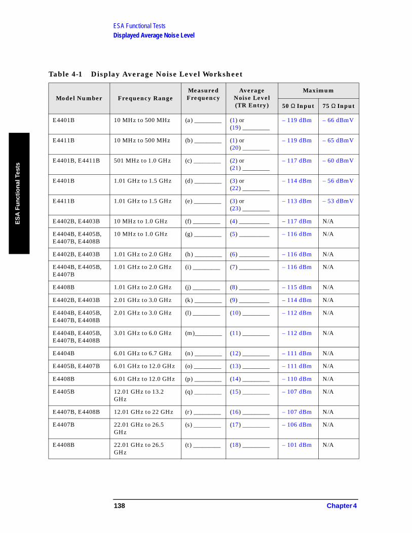
ESA Functional TestsDisplayed Average Noise Level
ES
A F
un
ctio
nal
Tes
ts
Table 4-1 Display Average Noise Level Worksheet
Model Number Frequency RangeMeasured Frequency
Average Noise Level (TR Entry)
Maximum
50 Ω Input 75 Ω Input
E4401B 10 MHz to 500 MHz (a) _________ (1) or (19) _________
– 119 dBm – 66 dBmV
E4411B 10 MHz to 500 MHz (b) _________ (1) or (20) _________
– 119 dBm – 65 dBmV
E4401B, E4411B 501 MHz to 1.0 GHz (c) _________ (2) or(21) _________
– 117 dBm – 60 dBmV
E4401B 1.01 GHz to 1.5 GHz (d) _________ (3) or(22) _________
– 114 dBm – 56 dBmV
E4411B 1.01 GHz to 1.5 GHz (e) _________ (3) or (23) _________
– 113 dBm – 53 dBmV
E4402B, E4403B 10 MHz to 1.0 GHz (f) _________ (4) __________ – 117 dBm N/A
E4404B, E4405B, E4407B, E4408B
10 MHz to 1.0 GHz (g) _________ (5) __________ – 116 dBm N/A
E4402B, E4403B 1.01 GHz to 2.0 GHz (h) _________ (6) __________ – 116 dBm N/A
E4404B, E4405B, E4407B
1.01 GHz to 2.0 GHz (i) _________ (7) __________ – 116 dBm N/A
E4408B 1.01 GHz to 2.0 GHz (j) _________ (8) __________ – 115 dBm N/A
E4402B, E4403B 2.01 GHz to 3.0 GHz (k) _________ (9) __________ – 114 dBm N/A
E4404B, E4405B, E4407B, E4408B
2.01 GHz to 3.0 GHz (l) _________ (10) _________ – 112 dBm N/A
E4404B, E4405B, E4407B, E4408B
3.01 GHz to 6.0 GHz (m)_________ (11) _________ – 112 dBm N/A
E4404B 6.01 GHz to 6.7 GHz (n) _________ (12) _________ – 111 dBm N/A
E4405B, E4407B 6.01 GHz to 12.0 GHz (o) _________ (13) _________ – 111 dBm N/A
E4408B 6.01 GHz to 12.0 GHz (p) _________ (14) _________ – 110 dBm N/A
E4405B 12.01 GHz to 13.2 GHz
(q) _________ (15) _________ – 107 dBm N/A
E4407B, E4408B 12.01 GHz to 22 GHz (r) _________ (16) _________ – 107 dBm N/A
E4407B 22.01 GHz to 26.5 GHz
(s) _________ (17) _________ – 106 dBm N/A
E4408B 22.01 GHz to 26.5 GHz
(t) _________ (18) _________ – 101 dBm N/A
138 Chapter 4

ESA Functional TestsFrequency Readout Accuracy
ES
A F
un
ction
al Tests
Frequency Readout Accuracy
Test Limits
Test Description
The frequency readout accuracy of the analyzer is tested with an input signal of known frequency. Frequency reference error is eliminated by using the same frequency standard for the analyzer and the synthesized sweeper.
Span Minimum) Maximum
10 MHz 1.48988 GHz 1.49012 GHz
100 kHz 1.4899988 GHz 1.4900012 GHz
Marker Count Accuracy with Counter Resolution at 1 Hz
1.489999999 GHz 1.490000001 GHz
ItemCritical Specifications
(for this test)Recommended Agilent Model
Signal Sources
Synthesized Sweeper 10 MHz to 1.5 GHzExternal Reference Input
8340A/B or 836XX Series
Adapters
Type-N (f), to APC 3.5(f)
1250-1745
Cables
Type-N, 152-cm (60-in)
11500D
BNC, 122-cm (48-in) 10503A
Additional Equipment for 75-Ohm Input
Pad, minimum loss 11852B
Type-N (f), to BNC (m), 75 Ω
1250-1534
Chapter 4 139

ESA Functional TestsFrequency Readout Accuracy
ES
A F
un
ctio
nal
Tes
ts
Figure 4-2 Equipment Setup
Procedure
1. Connect the equipment as shown in Figure 4-2. Remember to connect the 10 MHz REF OUT of the analyzer to the 10 MHz REF IN of the synthesized sweeper.
2. Perform the following steps to set up the equipment:
a. Press INSTRUMENT PRESET on the synthesized sweeper, then set the controls to:
CW, 1.490, GHzPOWER LEVEL, 10, – dBm
b. Press System, Power On/Preset, Preset Type (Factory), Preset on the analyzer, then wait for the preset routine to finish. Set the analyzer by pressing the following keys:
Frequency, 1.490, GHzSPAN, 10, MHzBW/Avg, Res BW, 100, kHzVideo BW, 30, kHz
CAUTION Use only 75 Ω cables, connectors, or adapters on analyzers with 75 Ω inputs, or damage to connectors will occur.
3. Press Peak Search on the analyzer to measure the frequency readout accuracy. Record this in the Marker Frequency Readout column in Table 4-2 on page 141.
4. Press Span, 100, kHz, BW/Avg, Res BW, 1, kHz, Video BW, 1, kHz.
5. Press Peak Search on the analyzer to measure the frequency readout accuracy. Record this in the Marker Frequency Readout column in Table 4-2 on page 141.
NOTE The Frequency Readout Accuracy in now complete. Continue with the Marker Count Accuracy functional check.
140 Chapter 4
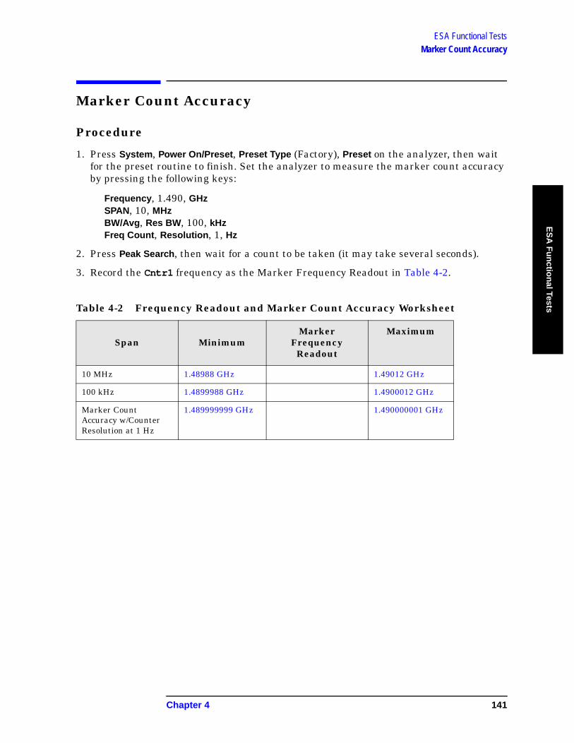
ESA Functional TestsMarker Count Accuracy
ES
A F
un
ction
al Tests
Marker Count Accuracy
Procedure
1. Press System, Power On/Preset, Preset Type (Factory), Preset on the analyzer, then wait for the preset routine to finish. Set the analyzer to measure the marker count accuracy by pressing the following keys:
Frequency, 1.490, GHzSPAN, 10, MHzBW/Avg, Res BW, 100, kHzFreq Count, Resolution, 1, Hz
2. Press Peak Search, then wait for a count to be taken (it may take several seconds).
3. Record the Cntr1 frequency as the Marker Frequency Readout in Table 4-2.
Table 4-2 Frequency Readout and Marker Count Accuracy Worksheet
Span MinimumMarker
Frequency Readout
Maximum
10 MHz 1.48988 GHz 1.49012 GHz
100 kHz 1.4899988 GHz 1.4900012 GHz
Marker Count Accuracy w/Counter Resolution at 1 Hz
1.489999999 GHz 1.490000001 GHz
Chapter 4 141

ESA Functional TestsFrequency Response (Flatness)
ES
A F
un
ctio
nal
Tes
ts
Frequency Response (Flatness)
Test Limits
Test Description
The output of the synthesized sweeper is fed through a power splitter to a power sensor and the analyzer. The synthesized sweeper’s power level is adjusted at 50 MHz to place the displayed signal at the analyzer center horizontal graticule line. Measurements are made at various points depending on the model being tested. The signal source amplitude is measured with a power meter to eliminate errors due to source flatness. The power meter is zeroed and calibrated before starting the measurement.
ESA Model Frequency Minimum (dB)
Maximum (dB)
E4411B & E4401B 9 kHz to 1.5 GHz –1.5 1.5
E4402B & E4403B 9 kHz to 3 GHz –1.5 1.5
E4404B 9 kHz to 3 GHz –1.5 1.5
3.01 GHz to 6.7 GHz –3.0 3.0
E4405B 9 kHz to 3 GHz –1.5 1.5
3.01 GHz to 6.7 GHz –3.0 3.0
6.71 GHz to 13.2 GHz –3.5 3.5
E4407B & E4408B 9 kHz to 3 GHz –1.5 1.5
3.01 GHz to 6.7 GHz –3.0 3.0
6.71 GHz to 13.2 GHz –3.5 3.5
13.21 GHz to 25 GHz –4.0 4.0
25 GHz to 26.5 GHz –4.5 4.5
ItemCritical Specifications
(for this test)Recommended Agilent Model
Signal Sources
Synthesized Sweeper
8340A/B or 836xx Series
Adapters
Type-N (f) to BNC (f) 1250-1474
APC 3.5 (f) to APC 3.5 (f)
5061-5311
BNC (f) to SMA (m) 1250-1237
142 Chapter 4
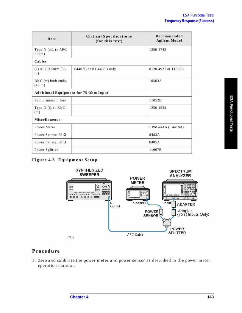
ESA Functional TestsFrequency Response (Flatness)
ES
A F
un
ction
al Tests
Figure 4-3 Equipment Setup
Procedure
1. Zero and calibrate the power meter and power sensor as described in the power meter operation manual.
Type-N (m), to APC 3.5(m)
1250-1743
Cables
(2) APC 3.5mm (36 in)
E4407B and E4408B only 8120-4921 or 11500E
BNC (m) both ends, (48 in)
10503A
Additional Equipment for 75-Ohm Input
Pad, minimum loss 11852B
Type-N (f), to BNC (m)
1250-1534
Miscellaneous
Power Meter EPM-441A (E4418A)
Power Sensor, 75 Ω 8483A
Power Sensor, 50 Ω 8485A
Power Splitter 11667B
ItemCritical Specifications
(for this test)Recommended Agilent Model
Chapter 4 143
ESA Functional TestsFrequency Response (Flatness)
ES
A F
un
ctio
nal
Tes
ts
2. Connect the equipment as shown in Figure 4-3.
CAUTION Use only 75 Ω cables, connectors, or adapters on analyzers with 75 Ω connectors, or damage to the connectors will occur.
3. Set the synthesized sweeper controls as follows:
FREQUENCY, Center Freq, 50, MHz
POWER LEVEL, –8, dBm
4. Press System, Power On/Preset, Preset Type (Factory), Preset on the analyzer and wait for the preset routine to finish. Set the analyzer by pressing the following keys.
FREQUENCY, 50, MHzCF Step, 50, MHzSPAN, 20, kHzAMPLITUDE, More, Y Axis Units, dBmAMPLITUDE, –10, dBmAMPLITUDE, Attenuation, 10, dBScale/Div, 2, dBBW/Avg, Res BW, 10, kHzVideo BW, 3, kHzPeak SearchFREQUENCY, Signal Track (On)
5. Adjust the synthesized sweeper power level for a marker amplitude reading of –14 dBm +/– 0.10 dB.
NOTE The power level of the synthesized sweeper remains unchanged for the duration of the test. For each new test frequency, the power sensor cal factor should be entered to minimize measurement errors.
6. Refer to Table 4-3 on page 145 Enter the marker readout amplitude for 50 MHz as displayed on the analyzer in the Analyzer Amplitude column.
7. Enter the power meter reading in the Power Meter Amplitude column.
8. Compute the flatness error at 50 MHz using the following equation and record the results in the Flatness Error column:
Flatness Error = Analyzer Amplitude – Power Meter Amplitude
9. Perform the following steps for each center frequency setting listed in Table 4-3 on page 145.
a. Tune the source to the next frequency listed in the Center Frequency column.
b. Enter the power sensor cal factor for the new test frequency.
144 Chapter 4

ESA Functional TestsFrequency Response (Flatness)
ES
A F
un
ction
al Tests
c. Tune the analyzer center frequency by pressing the ⇑ key or press FREQUENCY, Center Freq, “n”, and MHz (where “n” is the next test frequency in Table 4-3 on page 145).
d. Press Peak Search.
e. Enter the power meter reading in the Power Meter Amplitude column.
f. Enter the analyzer reading in the Analyzer Amplitude column.
g. Compute the flatness error using the following equation and record the results in the Flatness Error column:
Flatness Error = Analyzer Amplitude – Power Meter Amplitude
The flatness error should be less than the specified amount.
Table 4-3 Frequency Response Worksheet
Model Center Freq
Analyzer Amplitude
Power Meter
Amplitude
Flatness Error
Flatness Error Test
Limits(dB)
All Models 50 MHz ± 1.5
100 MHz ± 1.5
750 MHz ± 1.5
1250 MHz ± 1.5
1500 MHz ± 1.5
E4402B – E4408B 2000 MHz ± 1.5
2500 MHz ± 1.5
2999 MHz ± 1.5
E4402B – E4408B 4250 MHz ± 3.0
5750 MHz ± 3.0
6699 MHz ± 3.0
E4402B – E4408B 8000 MHz ± 3.5
9000 MHz ± 3.5
10000 MHz ± 3.5
11000 MHz ± 3.5
13199 MHz ± 3.5
E4407B & E4408B 14000 MHz ± 4.0
19000 MHz ± 4.0
24000 MHz ± 4.0
26500 MHz ± 4.5
Chapter 4 145

ESA Functional TestsReference Level Accuracy
ES
A F
un
ctio
nal
Tes
ts
Reference Level Accuracy
Test Limits
Test Description
A 50 MHz CW signal is applied to the Input of the analyzer. The amplitude of the source and the analyzer’s reference level are decreased in 10 dB steps. The analyzer marker functions are used to measure the amplitude difference between steps. Reference Level Accuracy is tested in both Log and Linear Scale Modes. Most of the error is contributed from the output attenuator inaccuracy in the synthesized sweeper and not the analyzer.
Reference LevelMinimum
(dB)Maximum
(dB)dBm dBmV
–30 21.76 Reference Reference
–20 31.76 –1.40 1.40
–10 41.76 –1.40 1.40
–40 11.76 –1.40 1.40
–50 1.76 –1.40 1.40
–60 –8.24 –1.40 1.40
–70 –18.24 –2.0 2.0
ItemCritical Specifications
(for this test)Recommended Agilent Model
Signal Sources
Synthesized Sweeper Output Level Accuracy0 to –15 dBm: ±1.0 dB–16 dBm to –63 dBm: ±1.4 dB≤ –64 dBm: ≥2.0 dB
8340A/B or 836XX Series
Adapters
Type-N (m), to BNC f)
1250-1476
Cables
Type-N, 152-cm (60-in)
11500D
BNC, 122-cm (48-in) 10503A
Additional Equipment for 75-Ohm Input
Pad, minimum loss 11852B
146 Chapter 4
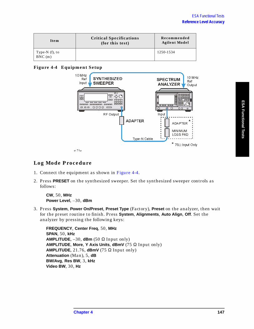
ESA Functional TestsReference Level Accuracy
ES
A F
un
ction
al Tests
Figure 4-4 Equipment Setup
Log Mode Procedure
1. Connect the equipment as shown in Figure 4-4.
2. Press PRESET on the synthesized sweeper. Set the synthesized sweeper controls as follows:
CW, 50, MHzPower Level, –30, dBm
3. Press System, Power On/Preset, Preset Type (Factory), Preset on the analyzer, then wait for the preset routine to finish. Press System, Alignments, Auto Align, Off. Set the analyzer by pressing the following keys:
FREQUENCY, Center Freq, 50, MHzSPAN, 50, kHzAMPLITUDE, –30, dBm (50 Ω Input only)AMPLITUDE, More, Y Axis Units, dBmV (75 Ω Input only)AMPLITUDE, 21.76, dBmV (75 Ω Input only)Attenuation (Man), 5, dBBW/Avg, Res BW, 3, kHzVideo BW, 30, Hz
Type-N (f), to BNC (m)
1250-1534
ItemCritical Specifications
(for this test)Recommended Agilent Model
Chapter 4 147
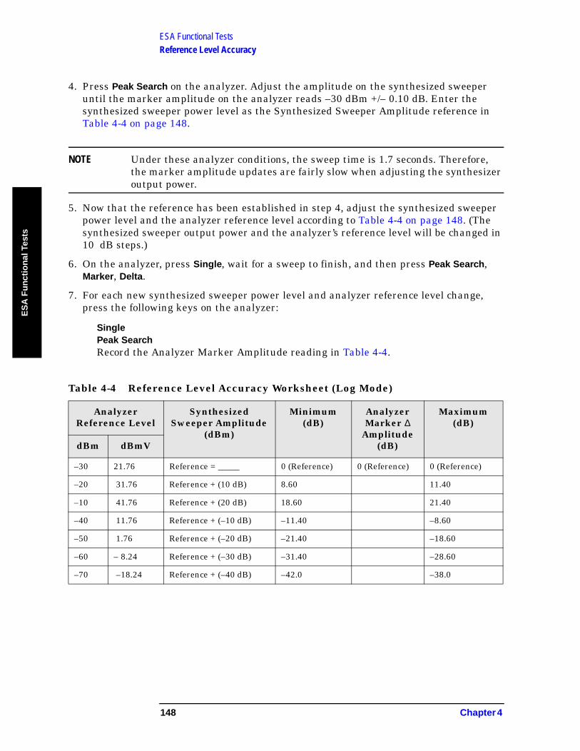
ESA Functional TestsReference Level Accuracy
ES
A F
un
ctio
nal
Tes
ts
4. Press Peak Search on the analyzer. Adjust the amplitude on the synthesized sweeper until the marker amplitude on the analyzer reads –30 dBm +/– 0.10 dB. Enter the synthesized sweeper power level as the Synthesized Sweeper Amplitude reference in Table 4-4 on page 148.
NOTE Under these analyzer conditions, the sweep time is 1.7 seconds. Therefore, the marker amplitude updates are fairly slow when adjusting the synthesizer output power.
5. Now that the reference has been established in step 4, adjust the synthesized sweeper power level and the analyzer reference level according to Table 4-4 on page 148. (The synthesized sweeper output power and the analyzer’s reference level will be changed in 10 dB steps.)
6. On the analyzer, press Single, wait for a sweep to finish, and then press Peak Search, Marker, Delta.
7. For each new synthesized sweeper power level and analyzer reference level change, press the following keys on the analyzer:
SinglePeak SearchRecord the Analyzer Marker Amplitude reading in Table 4-4.
Table 4-4 Reference Level Accuracy Worksheet (Log Mode)
Analyzer Reference Level
Synthesized Sweeper Amplitude
(dBm)
Minimum (dB)
Analyzer Marker ∆
Amplitude (dB)
Maximum (dB)
dBm dBmV
–30 21.76 Reference = _____ 0 (Reference) 0 (Reference) 0 (Reference)
–20 31.76 Reference + (10 dB) 8.60 11.40
–10 41.76 Reference + (20 dB) 18.60 21.40
–40 11.76 Reference + (–10 dB) –11.40 –8.60
–50 1.76 Reference + (–20 dB) –21.40 –18.60
–60 – 8.24 Reference + (–30 dB) –31.40 –28.60
–70 –18.24 Reference + (–40 dB) –42.0 –38.0
148 Chapter 4
ESA Functional TestsReference Level Accuracy
ES
A F
un
ction
al Tests
Linear Mode Procedure
1. Set the power level on the synthesized sweeper to –30 dBm by pressing Power Level, –30, dBm.
2. Set the analyzer by pressing the following keys:
Sweep, Sweep (Cont)AMPLITUDE, More, Y Axis Units, dBm (50 Ω Input)AMPLITUDE, –30, dBm (50 Ω Input)AMPLITUDE, More, Y Axis Units, dBmV (75 Ω Input)AMPLITUDE, +21.76, dBmV (75 Ω Input)Scale Type (Lin)
3. Adjust the amplitude on the synthesized sweeper until the marker amplitude on the analyzer reads –30 dBm +/– 0.10 dB. Enter the synthesized sweeper power level as the Synthesized Sweeper Amplitude reference in Table 4-5 on page 150.
NOTE Under these analyzer conditions, the sweep time is 1.7 seconds. Therefore, the marker amplitude updates are fairly slow when adjusting the synthesizer output power.
4. Now that the reference has been established in step 4, adjust the synthesized sweeper power level and the analyzer reference level according to Table 4-5 on page 150 (The synthesized sweeper output power and the analyzer’s reference level will be changed in 10 dB steps.)
5. On the analyzer, press Single, wait for a sweep to finish, and then press Peak Search, Marker, Delta.
6. For each new synthesized sweeper power level and analyzer reference level change, press the following keys on the analyzer:
SinglePeak Search
Record the Analyzer Marker Amplitude reading in Table 4-5
Chapter 4 149
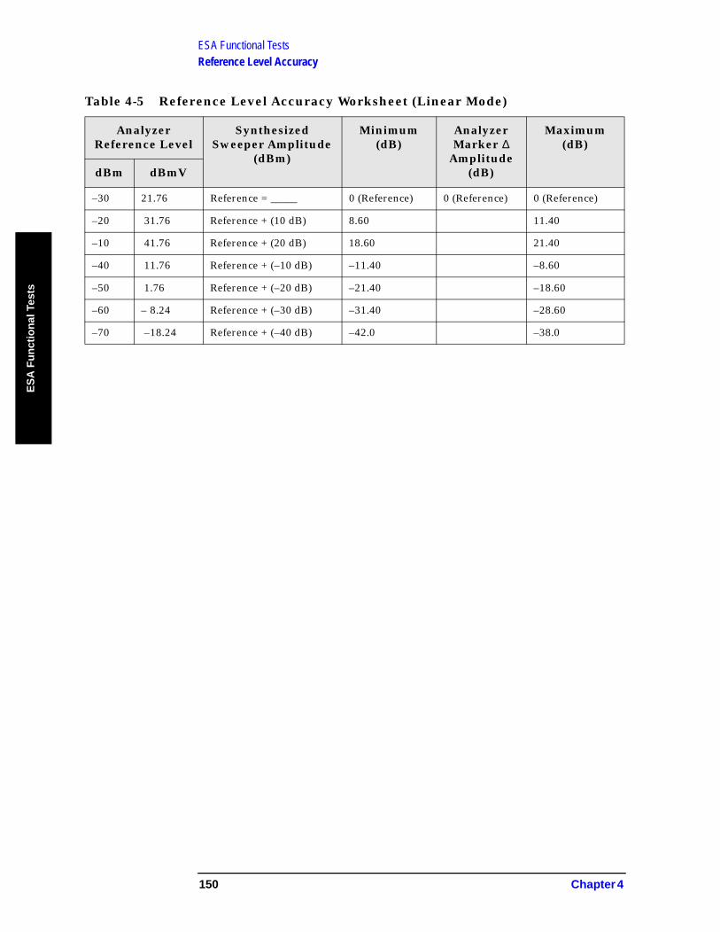
ESA Functional TestsReference Level Accuracy
ES
A F
un
ctio
nal
Tes
ts
Table 4-5 Reference Level Accuracy Worksheet (Linear Mode)
Analyzer Reference Level
Synthesized Sweeper Amplitude
(dBm)
Minimum (dB)
Analyzer Marker ∆
Amplitude (dB)
Maximum (dB)
dBm dBmV
–30 21.76 Reference = _____ 0 (Reference) 0 (Reference) 0 (Reference)
–20 31.76 Reference + (10 dB) 8.60 11.40
–10 41.76 Reference + (20 dB) 18.60 21.40
–40 11.76 Reference + (–10 dB) –11.40 –8.60
–50 1.76 Reference + (–20 dB) –21.40 –18.60
–60 – 8.24 Reference + (–30 dB) –31.40 –28.60
–70 –18.24 Reference + (–40 dB) –42.0 –38.0
150 Chapter 4

ESA Functional TestsResolution Bandwidth Switching Uncertainty
ES
A F
un
ction
al Tests
Resolution Bandwidth Switching Uncertainty
Test Limits
Test Description
To measure the resolution-bandwidth switching uncertainty, an amplitude reference is taken with the resolution bandwidth set to 1 kHz. The resolution bandwidth is changed to settings between 5 MHz and 3 kHz and the amplitude variation is measured at each setting using the marker delta function and compared to the specification. The span is changed as necessary to maintain approximately the same aspect ratio.
No equipment required for analyzer models E4401B and E4411B.
Resolution Bandwidth Minimum (dB) Maximum (dB)
1 kHz 0 (Ref) 0 (Ref)
3 kHz –0.3 dB 0.3 dB
10 kHz –0.3 dB 0.3 dB
30 kHz –0.3 dB 0.3 dB
100 kHz –0.3 dB 0.3 dB
300 kHz –0.3 dB 0.3 dB
1 MHz –0.3 dB 0.3 dB
3 MHz –0.3 dB 0.3 dB
5 MHz –0.6 dB 0.6 dB
ItemCritical Specifications
(for this test)Recommended Agilent Model
Cables
BNC, 9 inch 10502A
Adapter
Type N to BNC 1250-0780 or 1250-1476
Chapter 4 151

ESA Functional TestsResolution Bandwidth Switching Uncertainty
ES
A F
un
ctio
nal
Tes
ts
Figure 4-5 Equipment Setup
Procedure
NOTE The 50 MHz reference output will automatically be switched internally on the E4401B and E4411B and will not require any external connections. All other ESA analyzers require that the AMPTD REF OUT be connected to the INPUT to perform this test.
1. Press System, Power On/Preset, Preset Type (Factory), Preset on the analyzer. Wait for the preset routine to finish. Set the analyzer by pressing the following keys:
Input/Output, Amptd Ref (On) (E4401B and E4411B)Input/Output, Amptd Ref Out (On) (E4402B, E4403B, E4404B, E4405B, E4407B, and E4408B). Connect a cable from the AMPTD REF OUT to the INPUT 50 Ω, as shown in Figure 4-5 (E4402B, E4403B, E4404B, E4405B, E4407B, and E4408B).FREQUENCY, 50, MHzSPAN, 50, kHzAMPLITUDE, More, Y Axis Units, dBm (75 Ω Input only)AMPLITUDE, –20, dBmAMPLITUDE, Scale/Div, 1, dBBW/Avg, Res BW, 1, kHzVideo BW, 1, kHz
2. Press AMPLITUDE and use the knob to adjust the reference level until the signal appears five divisions (mid-screen) below the reference level. Press the following keys on the analyzer:
Peak SearchMarker, DeltaFREQUENCY, Signal Track (On)
3. Set the analyzer Resolution Bandwidth and Span according to Table 4-6 on page 153.
4. Press Peak Search, then record the ∆ Mkr 1 amplitude reading in Table 4-6.
152 Chapter 4
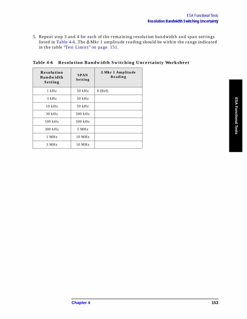
ESA Functional TestsResolution Bandwidth Switching Uncertainty
ES
A F
un
ction
al Tests
5. Repeat step 3 and 4 for each of the remaining resolution bandwidth and span settings listed in Table 4-6. The ∆ Mkr 1 amplitude reading should be within the range indicated in the table “Test Limits” on page 151.
Table 4-6 Resolution Bandwidth Switching Uncertainty Worksheet
Resolution Bandwidth
Setting
SPAN Setting
∆ Mkr 1 Amplitude Reading
1 kHz 50 kHz 0 (Ref)
3 kHz 50 kHz
10 kHz 50 kHz
30 kHz 500 kHz
100 kHz 500 kHz
300 kHz 5 MHz
1 MHz 10 MHz
3 MHz 10 MHz
Chapter 4 153

ESA Functional TestsScale Fidelity
ES
A F
un
ctio
nal
Tes
ts
Scale Fidelity
Test Limits
Test Description
A 50 MHz CW signal is applied from a synthesized sweeper to the input of the analyzer. The source is adjusted for a response at the reference level. The synthesized sweeper amplitude is adjusted to achieve a nominal amplitude below the reference level. The analyzer’s amplitude marker is compared to the actual source change to determine the scale fidelity error. Most of the error is the source’s output attenuator inaccuracy from the synthesized sweeper.
dB from Reference Level Minimum (dB) Maximum (dB)
–4 –1.0 1.0
–16 –1.4 1.4
–28 –1.4 1.4
–40 –1.4 1.4
–52 –1.4 1.4
–64 –2.0 2.0
ItemCritical Specifications
(for this test)Recommended Agilent Model
Signal Sources
Synthesized Sweeper Output Level Accuracy0 to –15 dBm: ±1.0 dB–16 dBm to –63 dBm: ±1.4 dB≤ –64 dBm: ≥2.0 dB
8340A/B or 836XX Series
Adapters
Type-N (m), to BNC (f)
1250-1476
Cables
Type-N, 152-cm (60-in)
11500D
BNC, 122-cm (48-in) 10503A
Additional Equipment for 75-Ohm Input
Pad, minimum loss 11852B
Type-N (f), to BNC (m)
1250-1534
154 Chapter 4
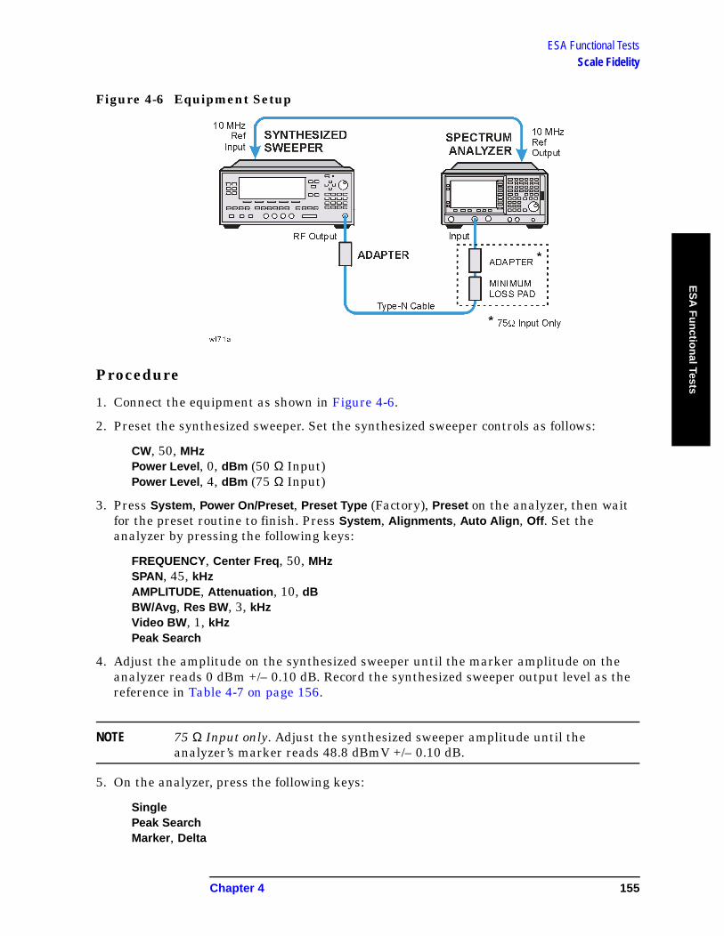
ESA Functional TestsScale Fidelity
ES
A F
un
ction
al Tests
Figure 4-6 Equipment Setup
Procedure
1. Connect the equipment as shown in Figure 4-6.
2. Preset the synthesized sweeper. Set the synthesized sweeper controls as follows:
CW, 50, MHzPower Level, 0, dBm (50 Ω Input)Power Level, 4, dBm (75 Ω Input)
3. Press System, Power On/Preset, Preset Type (Factory), Preset on the analyzer, then wait for the preset routine to finish. Press System, Alignments, Auto Align, Off. Set the analyzer by pressing the following keys:
FREQUENCY, Center Freq, 50, MHzSPAN, 45, kHzAMPLITUDE, Attenuation, 10, dBBW/Avg, Res BW, 3, kHzVideo BW, 1, kHzPeak Search
4. Adjust the amplitude on the synthesized sweeper until the marker amplitude on the analyzer reads 0 dBm +/– 0.10 dB. Record the synthesized sweeper output level as the reference in Table 4-7 on page 156.
NOTE 75 Ω Input only. Adjust the synthesized sweeper amplitude until the analyzer’s marker reads 48.8 dBmV +/– 0.10 dB.
5. On the analyzer, press the following keys:
SinglePeak SearchMarker, Delta
Chapter 4 155

ESA Functional TestsScale Fidelity
ES
A F
un
ctio
nal
Tes
ts
6. Record the marker delta reading in Table 4-7. At each new synthesized sweeper power level, press Single, Peak Search, and record the marker amplitude level.
Table 4-7 Scale Fidelity Worksheet
Synthesized Sweeper Level Minimum (dB) Marker
Level (dB)Maximum (dB)
Reference=______ 0 (Reference) 0 (Reference)
Reference –4 dB –5.0 –3.0
Reference –16 dB –17.40 –15.60
Reference –28 dB –29.40 –26.60
Reference –40 dB –41.40 –38.60
Reference –52 dB –53.40 –50.60
Reference –64 dB –66.0 –62.0
156 Chapter 4
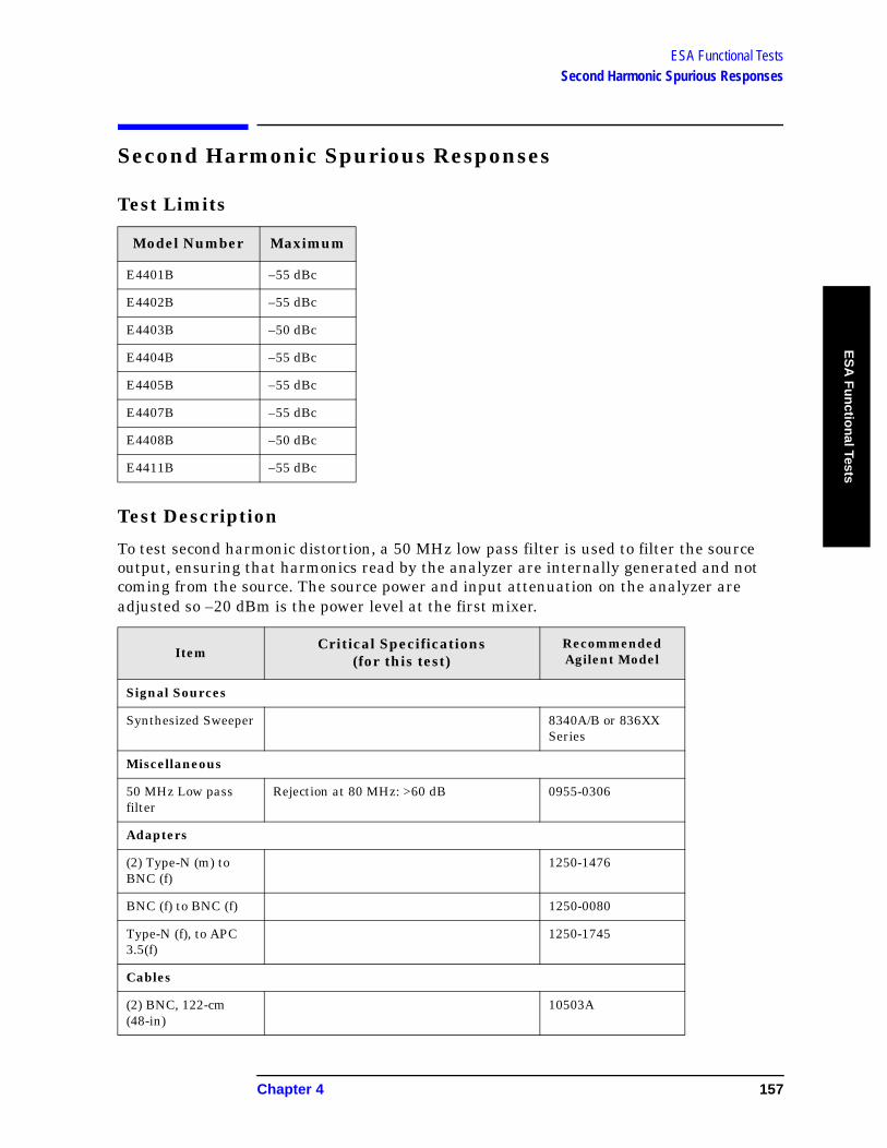
ESA Functional TestsSecond Harmonic Spurious Responses
ES
A F
un
ction
al Tests
Second Harmonic Spurious Responses
Test Limits
Test Description
To test second harmonic distortion, a 50 MHz low pass filter is used to filter the source output, ensuring that harmonics read by the analyzer are internally generated and not coming from the source. The source power and input attenuation on the analyzer are adjusted so –20 dBm is the power level at the first mixer.
Model Number Maximum
E4401B –55 dBc
E4402B –55 dBc
E4403B –50 dBc
E4404B –55 dBc
E4405B –55 dBc
E4407B –55 dBc
E4408B –50 dBc
E4411B –55 dBc
ItemCritical Specifications
(for this test)Recommended Agilent Model
Signal Sources
Synthesized Sweeper 8340A/B or 836XX Series
Miscellaneous
50 MHz Low pass filter
Rejection at 80 MHz: >60 dB 0955-0306
Adapters
(2) Type-N (m) to BNC (f)
1250-1476
BNC (f) to BNC (f) 1250-0080
Type-N (f), to APC 3.5(f)
1250-1745
Cables
(2) BNC, 122-cm (48-in)
10503A
Chapter 4 157
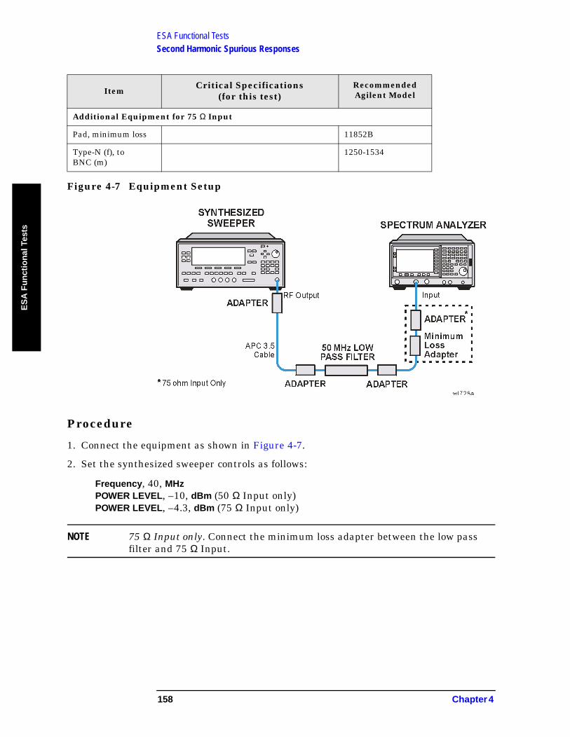
ESA Functional TestsSecond Harmonic Spurious Responses
ES
A F
un
ctio
nal
Tes
ts
Figure 4-7 Equipment Setup
Procedure
1. Connect the equipment as shown in Figure 4-7.
2. Set the synthesized sweeper controls as follows:
Frequency, 40, MHzPOWER LEVEL, –10, dBm (50 Ω Input only)POWER LEVEL, –4.3, dBm (75 Ω Input only)
NOTE 75 Ω Input only. Connect the minimum loss adapter between the low pass filter and 75 Ω Input.
Additional Equipment for 75 Ω Input
Pad, minimum loss 11852B
Type-N (f), to BNC (m)
1250-1534
ItemCritical Specifications
(for this test)Recommended Agilent Model
158 Chapter 4

ESA Functional TestsSecond Harmonic Spurious Responses
ES
A F
un
ction
al Tests
3. Press System, Power On/Preset, Preset Type (Factory), Preset on the analyzer. Wait for the preset routine to finish. Set the analyzer by pressing the following keys:
FREQUENCY, Center Freq, 40, MHzSPAN, 1, MHzAMPLITUDE, –10, dBm (50 Ω Input only)AMPLITUDE, 44, dBmV (75 Ω Input only)Attenuation (Man), 10, dBBW/Avg, Res BW, 30, kHz
4. Adjust the synthesized sweeper power level to place the peak of the signal at the reference level.
5. Set the analyzer by pressing the following keys:
SPAN, 50, kHzBW/Avg, Res BW, 1, kHzVideo BW, 100, Hz
6. Wait for two sweeps to finish, then press the following analyzer keys:
Peak SearchMkr →Mkr → CF StepMarker, DeltaFREQUENCY
7. Press the ⇑ key on the analyzer to step to the second harmonic (at 80 MHz). Press Peak Search. The marker delta amplitude reading should be less than the Maximum value listed in the Test Limits Table.
Chapter 4 159
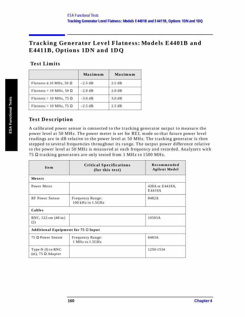
ESA Functional TestsTracking Generator Level Flatness: Models E4401B and E4411B, Options 1DN and 1DQ
ES
A F
un
ctio
nal
Tes
ts
Tracking Generator Level Flatness: Models E4401B and E4411B, Options 1DN and 1DQ
Test Limits
Test Description
A calibrated power sensor is connected to the tracking generator output to measure the power level at 50 MHz. The power meter is set for REL mode so that future power level readings are in dB relative to the power level at 50 MHz. The tracking generator is then stepped to several frequencies throughout its range. The output power difference relative to the power level at 50 MHz is measured at each frequency and recorded. Analyzers with 75 Ω tracking generators are only tested from 1 MHz to 1500 MHz.
Maximum Maximum
Flatness ≤ 10 MHz, 50 Ω –2.5 dB 2.5 dB
Flatness > 10 MHz, 50 Ω –2.0 dB 2.0 dB
Flatness > 10 MHz, 75 Ω –3.0 dB 3.0 dB
Flatness > 10 MHz, 75 Ω –2.5 dB 2.5 dB
ItemCritical Specifications
(for this test)Recommended Agilent Model
Meters
Power Meter 438A or E4418A, E4419A
RF Power Sensor Frequency Range: 100 kHz to 1.5GHz
8482A
Cables
BNC, 122-cm (48-in) (2)
10503A
Additional Equipment for 75 Ω Input
75 Ω Power Sensor Frequency Range: 1 MHz to 1.5GHz
8483A
Type-N (f) to BNC (m), 75 Ω Adapter
1250-1534
160 Chapter 4
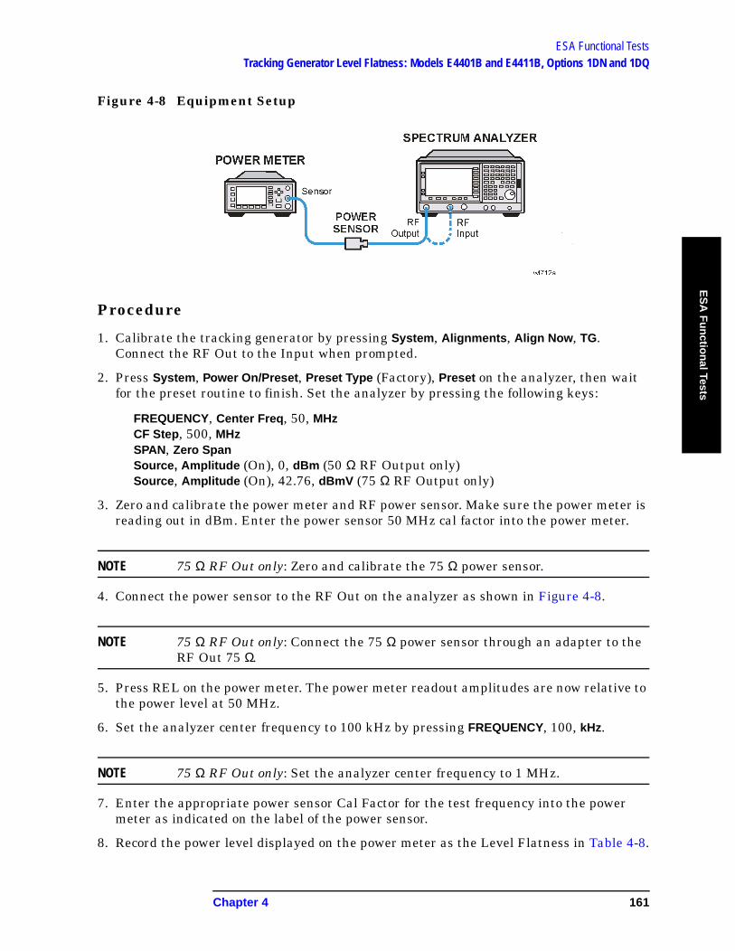
ESA Functional TestsTracking Generator Level Flatness: Models E4401B and E4411B, Options 1DN and 1DQ
ES
A F
un
ction
al Tests
Figure 4-8 Equipment Setup
Procedure
1. Calibrate the tracking generator by pressing System, Alignments, Align Now, TG. Connect the RF Out to the Input when prompted.
2. Press System, Power On/Preset, Preset Type (Factory), Preset on the analyzer, then wait for the preset routine to finish. Set the analyzer by pressing the following keys:
FREQUENCY, Center Freq, 50, MHzCF Step, 500, MHzSPAN, Zero SpanSource, Amplitude (On), 0, dBm (50 Ω RF Output only)Source, Amplitude (On), 42.76, dBmV (75 Ω RF Output only)
3. Zero and calibrate the power meter and RF power sensor. Make sure the power meter is reading out in dBm. Enter the power sensor 50 MHz cal factor into the power meter.
NOTE 75 Ω RF Out only: Zero and calibrate the 75 Ω power sensor.
4. Connect the power sensor to the RF Out on the analyzer as shown in Figure 4-8.
NOTE 75 Ω RF Out only: Connect the 75 Ω power sensor through an adapter to the RF Out 75 Ω.
5. Press REL on the power meter. The power meter readout amplitudes are now relative to the power level at 50 MHz.
6. Set the analyzer center frequency to 100 kHz by pressing FREQUENCY, 100, kHz.
NOTE 75 Ω RF Out only: Set the analyzer center frequency to 1 MHz.
7. Enter the appropriate power sensor Cal Factor for the test frequency into the power meter as indicated on the label of the power sensor.
8. Record the power level displayed on the power meter as the Level Flatness in Table 4-8.
Chapter 4 161
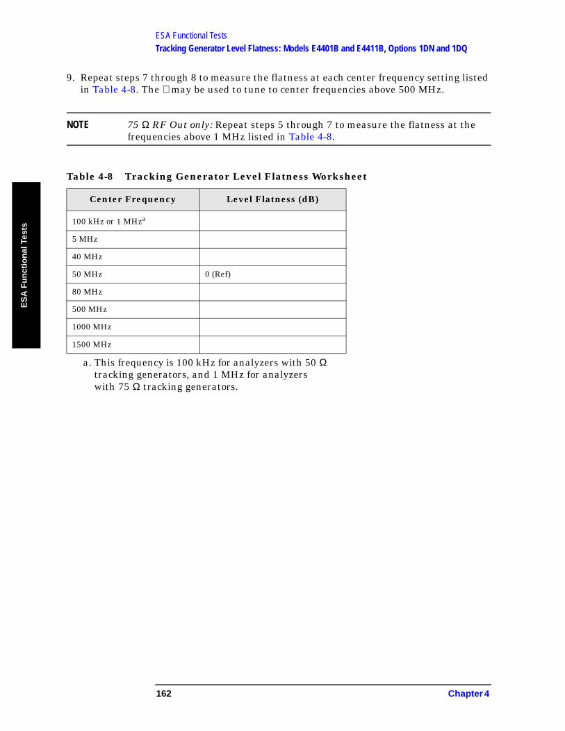
ESA Functional TestsTracking Generator Level Flatness: Models E4401B and E4411B, Options 1DN and 1DQ
ES
A F
un
ctio
nal
Tes
ts
9. Repeat steps 7 through 8 to measure the flatness at each center frequency setting listed in Table 4-8. The ⇑ may be used to tune to center frequencies above 500 MHz.
NOTE 75 Ω RF Out only: Repeat steps 5 through 7 to measure the flatness at the frequencies above 1 MHz listed in Table 4-8.
Table 4-8 Tracking Generator Level Flatness Worksheet
Center Frequency Level Flatness (dB)
100 kHz or 1 MHza
a. This frequency is 100 kHz for analyzers with 50 Ω tracking generators, and 1 MHz for analyzers with 75 Ω tracking generators.
5 MHz
40 MHz
50 MHz 0 (Ref)
80 MHz
500 MHz
1000 MHz
1500 MHz
162 Chapter 4
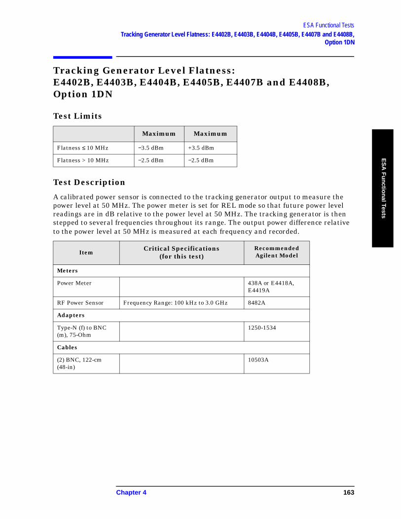
ESA Functional TestsTracking Generator Level Flatness: E4402B, E4403B, E4404B, E4405B, E4407B and E4408B,
Option 1DN
ES
A F
un
ction
al Tests
Tracking Generator Level Flatness: E4402B, E4403B, E4404B, E4405B, E4407B and E4408B, Option 1DN
Test Limits
Test Description
A calibrated power sensor is connected to the tracking generator output to measure the power level at 50 MHz. The power meter is set for REL mode so that future power level readings are in dB relative to the power level at 50 MHz. The tracking generator is then stepped to several frequencies throughout its range. The output power difference relative to the power level at 50 MHz is measured at each frequency and recorded.
Maximum Maximum
Flatness ≤ 10 MHz −3.5 dBm +3.5 dBm
Flatness > 10 MHz −2.5 dBm −2.5 dBm
ItemCritical Specifications
(for this test)Recommended Agilent Model
Meters
Power Meter 438A or E4418A, E4419A
RF Power Sensor Frequency Range: 100 kHz to 3.0 GHz 8482A
Adapters
Type-N (f) to BNC (m), 75-Ohm
1250-1534
Cables
(2) BNC, 122-cm (48-in)
10503A
Chapter 4 163
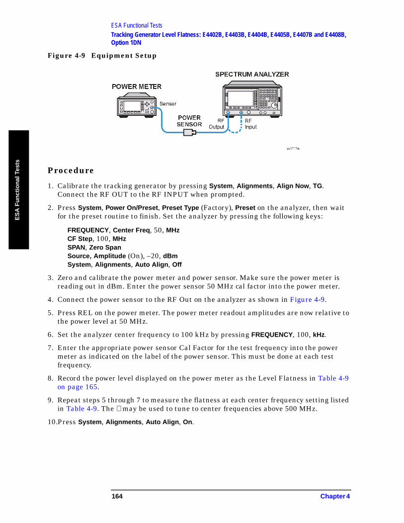
ESA Functional TestsTracking Generator Level Flatness: E4402B, E4403B, E4404B, E4405B, E4407B and E4408B, Option 1DN
ES
A F
un
ctio
nal
Tes
ts
Figure 4-9 Equipment Setup
Procedure
1. Calibrate the tracking generator by pressing System, Alignments, Align Now, TG. Connect the RF OUT to the RF INPUT when prompted.
2. Press System, Power On/Preset, Preset Type (Factory), Preset on the analyzer, then wait for the preset routine to finish. Set the analyzer by pressing the following keys:
FREQUENCY, Center Freq, 50, MHzCF Step, 100, MHzSPAN, Zero SpanSource, Amplitude (On), –20, dBmSystem, Alignments, Auto Align, Off
3. Zero and calibrate the power meter and power sensor. Make sure the power meter is reading out in dBm. Enter the power sensor 50 MHz cal factor into the power meter.
4. Connect the power sensor to the RF Out on the analyzer as shown in Figure 4-9.
5. Press REL on the power meter. The power meter readout amplitudes are now relative to the power level at 50 MHz.
6. Set the analyzer center frequency to 100 kHz by pressing FREQUENCY, 100, kHz.
7. Enter the appropriate power sensor Cal Factor for the test frequency into the power meter as indicated on the label of the power sensor. This must be done at each test frequency.
8. Record the power level displayed on the power meter as the Level Flatness in Table 4-9 on page 165.
9. Repeat steps 5 through 7 to measure the flatness at each center frequency setting listed in Table 4-9. The ⇑ may be used to tune to center frequencies above 500 MHz.
10.Press System, Alignments, Auto Align, On.
164 Chapter 4
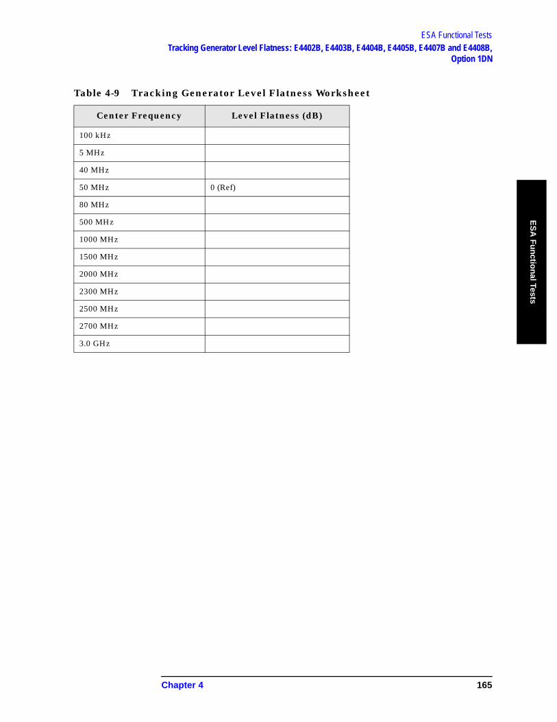
ESA Functional TestsTracking Generator Level Flatness: E4402B, E4403B, E4404B, E4405B, E4407B and E4408B,
Option 1DN
ES
A F
un
ction
al Tests
Table 4-9 Tracking Generator Level Flatness Worksheet
Center Frequency Level Flatness (dB)
100 kHz
5 MHz
40 MHz
50 MHz 0 (Ref)
80 MHz
500 MHz
1000 MHz
1500 MHz
2000 MHz
2300 MHz
2500 MHz
2700 MHz
3.0 GHz
Chapter 4 165
ESA Functional TestsTracking Generator Level Flatness: E4402B, E4403B, E4404B, E4405B, E4407B and E4408B, Option 1DN
ES
A F
un
ctio
nal
Tes
ts
166 Chapter 4

IndexIn
dex
Numerics1xEV-DO error messages
13001 to 13100, 80, 81
AAgilent Technologies URL, 2amplitude accuracy test, 102
option 1DS, 106amplitude linearity test, 115
Ccdma2000 error messages
10801 to 10900, 75cdmaOne error messages
10951 to 10975, 76command error messages, 33, 37
DDANL test, 107device-specific error messages
-399 to -300, 33, 3564 to 799, 33, 41
displayed average noise level. See DANL, 107
Eequipment
functional tests, 98warm-up time, 97
error history, 31error messages, 34
>10,000 (measurement application), 33, 54
10008 to 10517 (power suite), 5510524 to 10561 (phase noise), 7010601 to 10700 (GSM/EDGE),
7210701 to 10800 (W-CDMA), 7410801 to 10900 (cdma2000), 7510901 to 10925 (NADC), 7510926 to 10950 (PDC), 7610951 to 10975 (cdmaOne), 7610976 to 11000 (phase noise), 7612000 to 12999 (noise figure), 7713001 to 13100 (1xEV-OD), 80,
81-199 to -100 (command), 33, 371xEV-OD (13001 to 13100), 80,
81-299 to -200 (execution), 33, 35-399 to -300 (device-specific), 33,
35-499 to -400, 33, 3464 to 799 (device-specific), 33,
41
cdma2000 (10801 to 10900), 75cdmaOne (10951 to 10975), 76command (-199 to -100), 33, 37device-specific (-399 to -300), 33,
35device-specific (64 to 799), 33,
41empty error queue, 34example, 32execution (-299 to -200), 33, 35format, 32GSM/EDGE (10601 to 10700),
72measurement application
(>10,000), 33, 54NADC (10901 to 10925), 75noise figure (12000 to 12999), 77PDC (10926 to 10950), 76personality option, 33, 54phase noise (10524 to 10561), 70phase noise (10976 to 11000), 76power suite (10008 to 10517), 55query, 33, 34types, 33viewing messages in queue, 31W-CDMA (10701 to 10800), 74
error queuescapacity, 31clearing, 31empty message, 34front panel, 31overflow handling, 31remote interface (SCPI), 31SCPI remote interface, 31types, 31viewing entries, 31
errors0, 3410008 to 10517, 5510524 to 10561, 7010601 to 10700, 7210701 to 10800, 7410801 to 10900, 7510901 to 10925, 7510926 to 10950, 7610951 to 10975, 7610976 to 11000, 7612000 to 12999, 7713001 to 13100, 80, 81-199 to -100, 37-299 to -200, 35-399 to -300, 35-499 to -400, 3464 to 799, 41
execution errors, 33, 35
Fflatness, 139
frequency response, 139test description, 139
frequency readout accuracy test, 109
frequency response, 139flatness, 139test description, 139
frequency response (flatness) test, 111
front panelerror queue characteristics, 31
front panel error queue, 31functional testing
introduction, 96performance verification, 96
functional testsbefore performing, 97equipment list, 98introduction, 95vs performance verification
tests, 96warm-up time, 97See also individual functional
tests, 95
GGSM/EDGE error messages
10601 to 10700, 72
Iinformational messages, 30
descriptions, 82display location, 82
Mmeasurement application error
messages>10,000, 33, 54
messageserror, 34informational, 82status, 86
NNADC error messages
10901 to 10925, 75noise figure error messages
12000 to 12999, 77
PPDC error messages
10926 to 10950, 76
Index 167

IndexIn
dex
performance verification tests vs functional tests, 96
personality error messages, 33, 54
phase noise error messages10524 to 10561, 7010976 to 11000, 76
pop-up messages, 30power suite error messages
10008 to 10517, 55
Qqueries
error messages, 33, 34
Rremote interface (SCPI) error
queue, 31
SSCPI interface error queue, 31second harmonic distortion test,
118status messages, 30
descriptions, 86display location, 86
Ttest descriptions
frequency response, 139tests. See functional tests
UURL (Agilent Technologies), 2user error messages, 30
WW-CDMA error messages
10701 to 10800, 74
168 Index