Embed Size (px)
Citation preview

GEK-95353
�GE Industrial Systems
Instructions
Vertical Induction Motors
High ThrustHollow and Solid-ShaftIn-Line Solid-ShaftFrames 182-405 NEMA Type P Base
Weather Protected Type I

GEK-95353
2
SAFETY PRECAUTIONS
High voltage and rotatingparts can cause serious orfatal injuries. Installation,operation, and mainte-nance of electric machin-
ery should be performed by qualified per-sonnel. Familiarization with NEMA Publi-cation MG-2, Safety Standard for Con-struction and Guide for Selection, Installa-tion and Use of Electric Motors and Gen-erators, the National Electrical Code, andsound local practices is recommended.
For equipment covered in this instructionbook, it is important to observe safety pre-cautions to protect personnel from possi-ble injury. Among the many considerations,personnel should be instructed to:
• Avoid contact with energized circuits orrotating parts.
• Avoid by-passing or rendering inopera-tive any safeguards or protective de-vices.
• Avoid use of automatic-reset thermalprotection where unexpected starting ofequipment might be hazardous to per-sonnel.
• Avoid contact with capacitors until safedischarge procedures have been fol-lowed.
• Be sure that the shaft key is fully cap-tive before the motor is energized.
• Avoid extended exposure in closeproximity to machinery with high noiselevels.
• Use proper care and procedures inhandling, lifting, installing, operating,and maintaining the equipment.
• Do not lift anything but the motor withthe motor lifting means.
Safe maintenance practices by qualifiedpersonnel are imperative. Before startingmaintenance procedures, be positive that:
• Equipment connected to the shaft willnot cause mechanical rotation.
• Main machine windings and all acces-sory devices associated with the workarea are disconnected from electricalpower sources.
If a high-potential insulation test is re-quired, procedure and precautions out-lined in NEMA Standards MG-1 and MG-2should be followed.
Failure to properly ground the frame of thismachine can cause serious injury to per-sonnel. Grounding should be in accor-dance with the National Electrical Codeand consistent with sound local practice.
These instructions do not purport to cover all of the details or variations in equipment nor to provide for every possiblecontingency to be met in connection with installation, operation, or maintenance. Should further information be desiredor should particular problems arise which are not covered sufficiently for the purchaser’s purposes, the matter should bereferred to the General Electric Company.
© Copyright 1999 General Electric Company

GEK-95353
3
Table of Contents
Subject Page
Safety Warnings......................................................................................................................2Introduction ........................................................................................................................4Receiving, Handling, and Storage............................................................................................5Unpacking ........................................................................................................................5Installation ........................................................................................................................5
Location and Mounting ...............................................................................................6Pump and System Precautions .....................................................................................6Alignment of Solid Shaft Motors .................................................................................6Couplings for Hollow-Shaft Motors.............................................................................6
Self Release Couplings.....................................................................................7Bolted Couplings .............................................................................................9Non-Reverse Couplings ...................................................................................9
Power Supply and Connections .................................................................................10Wiring and Grounding....................................................................................10Allowable Voltage Frequency ........................................................................10Position of the Conduit Box...........................................................................11
Lubrication................................................................................................................11Operation ......................................................................................................................11
Steps Prior to Initial Startup ......................................................................................11Initial Startup ............................................................................................................13Jogging and Repeat Starts .........................................................................................14
Maintenance ......................................................................................................................14General......................................................................................................................14General Cleanliness....................................................................................................15Coupling Maintenance ...............................................................................................15Relubrication.............................................................................................................15
Oil Lubricated Bearings .................................................................................15Grease Lubricated Bearings ...........................................................................16
End-Play Adjustment ............................................................................................................18General .....................................................................................................................18Lower Thrust Bearings – 182-286 Frames, Grease Lubricated ...................................18Ball Thrust Bearings – 320-405 Frames, Oil Lubricated .............................................18Bearing Replacement.................................................................................................19Insulation and Winding Maintenance..........................................................................20
General..........................................................................................................20Vacuum and Compressed Air Cleaning ..........................................................20Cleaning with Water and Detergent................................................................20Cleaning with Solvents...................................................................................21Re-Varnishing Windings ................................................................................21
Renewal Parts ......................................................................................................................21Trouble Shooting Chart.........................................................................................................22

GEK-95353
4
VERTICAL INDUCTION MOTORSHIGH THRUST
HOLLOW AND SOLID-SHAFTIN-LINE SOLID-SHAFT
FRAMES 182-405 NEMA TYPE P BASEWEATHER PROTECTED TYPE I
I. INTRODUCTION
General Electric high-thrust vertical motorscovered by these instructions are carefullyconstructed of high-quality materials andare designed to give long and trouble-freeservice when properly installed and main-tained. These motors are generally used todrive pumps.
Both HOLLOW-SHAFT and SOLID-SHAFT motors are described in this in-struction book. hollow-shaft constructionis available in frame sizes 213 and largerand solid-shaft is available in 182 andlarger frames. Figure 1 shows a typical213-286 frame hollow-shaft motor andFigure 2 shows the 324-405 frame con-struction. The solid-shaft construction issimilar except that the top half-coupling isomitted, and the motor shaft extends outthe bottom of the motor. See Figures 3and 4. Solid-shaft high-thrust motors arenot suitable for driving loads that imposesignificant radial load on the motor shaft;they should not, for example. be usedfor belt-drive applications.
Motors may be supplied with differentbearing arrangements for various externalthrust conditions imposed by the pump,such as different magnitudes of down-thrust and either momentary or continuousup-thrust. A typical high-thrust motorwith angular-contact ball bearings is
shown in Figures 1 and 2. This standardconstruction is for high continuous down-thrust and is suitable for momentary up-thrust capacity of a high-thrust motor.NOTE THAT ANGULAR-CONTACTBEARINGS CAN ONLY CARRYTHRUST IN ONE DIRECTION.
IN-LINE motors are designed to bemounted on pumps which are directly inthe pipe-line and are also covered by thisinstruction book. These motors have twoopposed-mounted angular-contact ballthrust bearings at the top end of the motor(182-286 bearings are in bottom end ofthe motor (182-286 bearings are in bot-tom end) so they can carry either up ordown thrust. The lower guide bearing is aradial-ball type and also carries any radialload imposed by the pump. IN-LINEmotors are always of the solid-shaft type.
Since overloading greatly reduces bearinglife, the amount of thrust applied shouldnot exceed the recommended values.
This instruction book applies to motorswith Weather-Protected I enclosures asdefined by NEMA. These are “open”motors.
Weather-Protected I motor construction isshown in Figures 1 and 2 for hollow-shaftmotors and Figures 3 and 4 for solid-shaftmachines.

GEK-95353
5
II. RECEIVING, HANDLING, ANDSTORAGE
Each motor should be carefully examinedwhen received and a claim filed with thecarrier for any damage. The nearest officeof the General Electric Company may of-fer guidance.
The motor should be liftedby the lugs provided. Theselugs are intended for liftingthe motor only and must notbe used to lift any additional
Weight. Be careful not to touch overheadpower lines with lifting equipment. Failureto observe this warning may result in per-sonal injury or death.
If the motor is not to be installed immedi-ately, it should be stored in a clean, drylocation. Precautions should be taken toprevent the entrance of moisture, dust, ordirt during storage and installation. Pre-cautions are taken by the factory to guardagainst corrosion. The machined parts areslushed to prevent rust during shipment.Examine the parts carefully for rust andmoisture if the equipment is to be stored,and re-slush where necessary.
Motors are shipped without oil in thebearing reservoirs (320 frame and larger).An oil film remains on the bearings, but ifthe storage period is to exceed threemonths, the reservoirs should be filled. Itis suggested that such oil-filled motors beconspicuously tagged in order to preventmishandling which would cause oil spill-age and subsequent damage to the internalparts of the motor. When filling for stor-age, fill to the maximum level shown onthe gage or approximately ½” over themark showing the standstill level. Beforeoperating the motor, drain this oil and re-fill with fresh oil.
See instructions under Relubrication foroil recommendations.
During storage, windings should be pro-tected from excessive moisture absorptionby some safe and reliable method of heat-ing. Space heaters, if supplied, may beused for this purpose. The temperature ofthe windings should always be maintaineda few degrees above the temperature ofthe surrounding air. It is recommendedthat motors in storage be inspected, thewindings meggered, and a log of pertinentdata kept. Any significant decrease in in-sulation resistance should be investigated.
If the motor is to be in storage for overone year, it is recommended that compe-tent technical inspection service be ob-tained to ensure that the storage has beenadequate and that the motor is suitable forservice. Contact your nearest GeneralElectric Sales office to arrange for inspec-tion service.
III. UNPACKING
If the machine or machine parts have beenexposed to low temperatures, unpack itonly after it has reached the temperatureof the room in which it will be unpackedor located; otherwise sweating will occur.
IV. INSTALLATION
Installation should be in accor-dance with the National ElectricalCode and consistent with soundlocal practices. Coupling guardsand belt enclosures should be
installed as needed to protect against accidentalcontact with moving parts. Machines accessibleto personnel should be further guarded byscreening, guard rails or other suitable enclosureto prevent anyone from coming into contact withthe equipment. This is especially important formotors that are remotely or automatically con-trolled or have automatic re-setting overloadrelays, since such motors may start unexpect-edly. Failure to observe these precautions mayresult in injury or death to personnel.
GEK-95353
6
A. Location and Mounting
Allow enough space around themotor to permit free flow of venti-lating air and to maintain an ambienttemperature not over 40ºC. Where achoice of locations is possible, installthe motor so that it will be subjectedto the least amount of dirt, dust, liq-uids, or other harmful materials.Mount the motor securely on a level,firm foundation, align accuratelywith the driven equipment, andtighten bolts securely.
Weather-Protected Type I motorsmay be installed in indoor locationswith relatively high moisture contentor sheltered outdoor locations in dryclimates.
If ignitable dust or lint ispresent, the surface tem-perature of space heaters, ifsupplied, should not ex-ceed 80% of the ignitiontempera-
ture. Refer to space heater nameplate orfactory for information on surface tempera-ture. Dust and/or lint should not be allowedto build up around the surface of the spaceheaters. Failure to observe these precau-tions may result in damage to equipment,injury to personnel, or both.
Installation of the machinewhere hazardous, flamma-ble, or combustible vaporsor dusts present a possib-lity of explosion or fire
should be in accordance with The nationalelectrical code, articles 500-503, and consis-tent with sound local practices. Extremecare is required for all explosion-proof mo-tors and all motors supplied with an explo-sion-proof or dust-ignition proof accessorydevice or conduit box since any nicks orburrs in the sealing surfaces during disas-sembly and reassembly may destroy theexplosion-proof or dust-ignition proof fea-tures. Failure to observe these precautionsmay result in damage to the equipment, in-jury of personnel, or both.
B. Pump and System Precautions
Some precautions are necessary toassure satisfactory operation ofmotors in pumping service. Thepacking gland in the pump headshould be kept in good condition sothat the liquid being pumped will notbe forced out along the shaft andenter the motor through the lowerbearing housing.
Motors driving pumps in pressuresystems where the pressure is main-tained after shutdown should beprotected from overspeeding bycheck valves or non-reverse cou-plings.
The SYSTEM REED CRITICALFRE-QUENCY should be 25% orbelow motor operating speed in or-der to avoid excessive vibration.
C. Alignment of Solid-Shaft Motors
Accurate mechanical lineup is essen-tial for successful operation. Me-chanical vibration and roughnesswhen the motor is running may indi-cate poor alignment. In general,lineup by straight edge across andfeeler gages between coupling halvesis not sufficiently accurate. It is rec-ommended that the lineup bechecked with dial indicators. Thespace between coupling hubs shouldbe maintained as recommended bythe coupling manufacturer.
D. Couplings for Hollow-ShaftMotors
Vertical hollow-shaft motors are de-signed for driving deep-well turbine-type pumps and can be equippedwith either self-release,

GEK-95353
7
bolted, or non-reverse couplings asdescribed in the following sections.These couplings are located at thetop of the motor and allow pumpimpeller position to be adjusted eas-ily. The type of coupling is specifiedby the customer. Remove the topcap for access to the coupling.
Two slots are provided in the out-side rim of the couplings so that abar can be inserted to keep the as-sembly from turning while the ad-justment is being made. A couplingbolt can be screwed into one of theextra tapped holes in the top end-shield to provide a stop for the bar.
To prevent breakage, coupling boltsmust be tightened to torque valuesindicated below for bolted or non-reverse couplings.
Bolt Size Torque
1/4 10 lb ft.3/8 20 lb. ft.
5/16 37 lb. ft.1/2 90 lb. ft.5/8 180 lb. ft.3/4 320 lb. ft.1 710 lb. ft.
It shall be the installer’s re-sponsibility in all cases toascertain that these torquevalues are used and main-tained. This shall include
those instances when the the couplingcomes mounted in the motor failure tocomply may cause the c oupling bolts tobreak with resultant extensive damage tothe equipment.
1. Self-Release Couplings
Should the motor accidentallybe run in the reverse direction,the pump line-shaft joints mayunscrew. The self-releasecoupling acts to limit theamount of unscrewing. In
normal operation, torque fromthe motor is transmitted by thelower half-coupling throughthe driving pins to the upperhalf-coupling and then to thepump shaft. If reversal occursand the pump shaft starts tounscrew and lengthen, the up-per half of the self-releasecoupling is lifted up off of thedriving pins, thus uncouplingthe pump from the motor. SeeFigure 2 where a self-releasecoupling is shown to the left ofthe shaft center-line.
NOTE THAT SELF-RELEASE COUPLINGSCANNOT CARRY UP-THRUST.
Proper functioning of a self-release coupling depends uponseveral factors. The pumpshaft adjusting nut must be se-curely attached to the top half-coupling and the top half-coupling must not bind on thelower half. Otherwise, the ad-justing nut lock-screw maybreak instead of the couplinghalves separating. Should thishappen, the motor would con-tinue to drive the pump line-shaft and the joints wouldcontinue to unscrew. Seriousdamage to both motor and lineshaft may result. Clearancebetween the coupling halvesshould be checked by placingthe top half-coupling in posi-tion prior to installing the mo-tor. It should drop into placeand rest solidly on the lowerhalf-coupling without forcing.
GEK-95353
8
Proper alignment of the pumphead-shaft within the motorhollow-shaft is also important.After the coupling releases, itno longer holds the pump shaftcentered. If the alignment isnot good, the motor shaftwhich is still rotating may rubthe pump shaft which hasstopped and damage will re-sult.
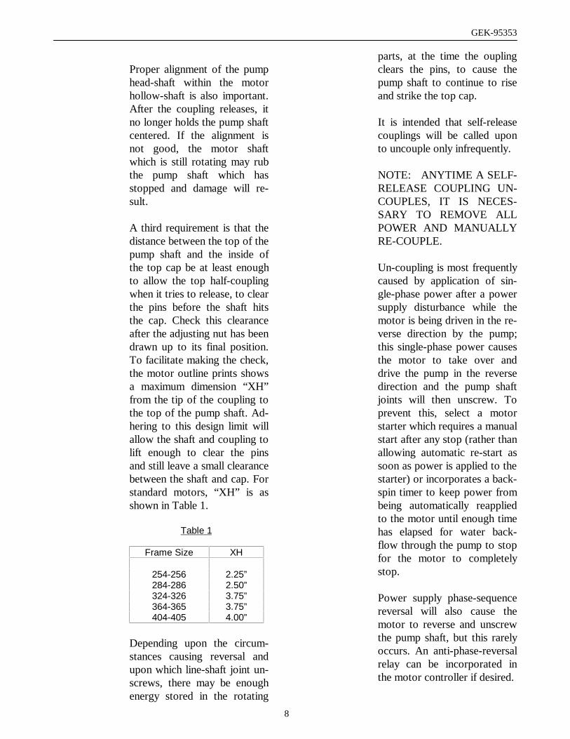
A third requirement is that thedistance between the top of thepump shaft and the inside ofthe top cap be at least enoughto allow the top half-couplingwhen it tries to release, to clearthe pins before the shaft hitsthe cap. Check this clearanceafter the adjusting nut has beendrawn up to its final position.To facilitate making the check,the motor outline prints showsa maximum dimension “XH”from the tip of the coupling tothe top of the pump shaft. Ad-hering to this design limit willallow the shaft and coupling tolift enough to clear the pinsand still leave a small clearancebetween the shaft and cap. Forstandard motors, “XH” is asshown in Table 1.
Table 1
Frame Size XH
254-256 2.25”284-286 2.50”324-326 3.75”364-365 3.75”404-405 4.00”
Depending upon the circum-stances causing reversal andupon which line-shaft joint un-screws, there may be enoughenergy stored in the rotating
parts, at the time the ouplingclears the pins, to cause thepump shaft to continue to riseand strike the top cap.
It is intended that self-releasecouplings will be called uponto uncouple only infrequently.
NOTE: ANYTIME A SELF-RELEASE COUPLING UN-COUPLES, IT IS NECES-SARY TO REMOVE ALLPOWER AND MANUALLYRE-COUPLE.
Un-coupling is most frequentlycaused by application of sin-gle-phase power after a powersupply disturbance while themotor is being driven in the re-verse direction by the pump;this single-phase power causesthe motor to take over anddrive the pump in the reversedirection and the pump shaftjoints will then unscrew. Toprevent this, select a motorstarter which requires a manualstart after any stop (rather thanallowing automatic re-start assoon as power is applied to thestarter) or incorporates a back-spin timer to keep power frombeing automatically reappliedto the motor until enough timehas elapsed for water back-flow through the pump to stopfor the motor to completelystop.
Power supply phase-sequencereversal will also cause themotor to reverse and unscrewthe pump shaft, but this rarelyoccurs. An anti-phase-reversalrelay can be incorporated inthe motor controller if desired.

GEK-95353
9
To prevent un-coupling on ini-tial start-up, check motorstalling the upper half-correct.To reverse direction of rota-tion, interchange any twopower leads.
2. Bolted Couplings
Bolted couplings allow up-thrustfrom the pump to be taken by themotor bearings. This type of cou-pling is similar to a self-release cou-pling except that the driving pins arereplaced by bolts, which should besecurely tightened to hold the twohalves of the coupling together sothat torque is transmitted by facefriction. See torque requirements onpage 6. This type of coupling doesnot have the self-release feature andallows reverse rotation.
See the self-release coupling shownto the left of the motor centerline inFigure 2 which is applicable tobolted couplings except that theheadless drive pins are replaced bybolts as explained above.
3. Non-Reverse Couplings
The non-reverse type of coupling, asshown to the right of the motorcenterline in Figures 1 and 2, is alsoa bolted type and, in addition, itkeeps the pump and motor from ro-tating in the reverse direction. Thus,it not only prevents damage fromoverspeeding and damage to water-lubricated pump shaft bearings,when during shutdown the residualwater in the system drives the pumpin the reverse direction. This type ofcoupling also allows up-thrust fromthe pump to be carried by the motor
bearings. Motor torque is transmit-ted to the pump shaft through thetwo halves of the coupling which arebolted together. See required bolttorques.
The operation of a non-reverse cou-pling is explained as follows: Whenthe motor is started in the correct orforward direction, the ratchet pinsare lifted by the ratchet teeth, andare held up by centrifugal force andfriction when motor speed becomeshigh enough. When power is re-moved, the speed decreases and thepins fall. At the instant of reversal, apin will catch on a ratchet tooth andprevent backward rotation. Thenumber of pins differs from thenumber of teeth to multiply thenumber of stopping positions.
A very rapid decrease in speed canresult in acceleration forces greatenough to prevent the pins fromdropping. This condition is furtheraggravated when the pins becomedirty and their action sluggish. If thetime from shutdown (the instant the“stop” button is pressed) to zerospeed is greater than two seconds,operation will be satisfactory.
To permit operation when stoppingtime is less than two seconds, thepins are spring-loaded. For thosecases involving cycling (frequentstarting and stopping) and stoppingtimes greater than two seconds, thesprings may be removed to decreasewear on the ratchet plate.
Pins and springs are made of heat-treated stainless steel.

GEK-95353
10
A complete non-reverse couplingconsists of a self-release couplingplus a non-reverse assembly, whichincludes pin carrier, pins, springs, pinretaining plate, and cap-screws. Onmotors covered by this instructionbook, the ratchet teeth are an integralpart of the endshield cover casting.
A self-release or a bolted couplingcan be converted to a non-reversecoupling on 326-405 frame motorswithout disturbing the adjustment ofthe pump shaft nut. The non-reverseassembly will normally be receivedas a unit. To assemble it onto themotor, loosen the three small capscrews that hold the pin-retainingplate so this plate can be centeredduring assembly. Next, remove thedrive-pins or bolts from the lowerhalf coupling. Then slide the non-reverse assembly down over the tiphalf-coupling. Next, insert the longcap screws through the plate, pincarrier, and top coupling and intothe lower coupling. Tighten themsecurely so that torque will betransmitted by friction between thecoupling faces rather than throughthe bolts. See torque requirements.Finally tighten the three small capscrews to secure the pin-retainingplate. On 213-286 frame machines,the pump shaft nut must be removedand the bolted or self-release cou-pling replaced with a non-reversecoupling.
The top half of the coupling shouldseat solidly on the lower half and thepins should touch the bottom of thepockets between the teeth in theratchet. The clearance between thepin-carrier and the top of the ratchetteeth should be between 1/16” and1/8”.
When installing a non-reverse cou-pling, do not use lubricant. Lubrica-tion will lower the coefficient offriction between pins and pin-carrierand the pins may not stay up whenmotor reaches full speed.
Motors shipped from stock mayhave their top couplings and non-reverse assemblies packaged sepa-rately. They can be installed as de-scribed in previous paragraphs.
E. Power Supply and Connections
1. Wiring and Grounding
Motor and control wiring,over-load protection, andgrounding should be in ac-cordance with the nationalelectrical code and consis-
tent with sound local practices. Failure toobserve these precautions may result indamage to the equipment, injury to per-sonnel, or both.
Stator winding connectionsshould be made as shown onthe connection diagram or inaccordance with the wiringdiagram attached to the insideof the conduit box cover. For3-lad motors, no connectiondiagram is needed or supplied.
The motor frame may begrounded by attaching aground strap from a knownground point to the groundingbolt in the conduit box.
2. Allowable Voltage andFrequency
The power supply must agree withthe motor nameplate voltage andfrequency. Motors will operate (but

GEK-95353
11
with characteristics somewhat dif-ferent from nameplate values) online voltages within ±10% of name-plate value or frequency within .±5% and a combined variation notto exceed ±10%.
3. Position of the Conduit Box
When mounting conditionspermit, the conduit box may beturned so that entrance can bemade upward, downward, orfrom either side.
F. Lubrication
Motors with oil-lubricated bearings(324-405 frames) are shipped with-out oil. Before starting the motor,fill each reservoir to the stand-stilllevel shown on the sight gage. Becareful to keep dirt out of the lubri-cant and bearing housing.
Use only the oil specified on the lu-brication nameplate or the lubrica-tion instructions supplied with eachmotor. See relubrication and TableII and lube nameplate for oil gradeand viscosity and further instruc-tions.
If reservoirs have had no oil in themduring storage period, drain out thisold oil and refill reservoir with freshoil when installing the motor for op-eration.
V. OPERATION
Before energizing the motorfor the first time or after anextended shut-down, it isadvisable to check insula-tion resistance, power
supply and mechanical freedom of the mo-tor. If the motor has been stored in a damplocation, dry it out thoroughly before oper-ating.
Be sure that the motor isnot running and the powersupply is disconnected be-fore working on motor.
A. Steps Prior to Initial Start-UpAfter a Long Idle Period
1. Check insulation resistance asindicated in the caution above.
Before measuring insula-tion resistance, the ma-chine must be at stand-stilland all windings to betested must be electricallyconnected
To the frame and to ground for a time suffi-cient to remove all residual electrostaticcharge. Failure to observe these precau-tions may result in injury to personnel.
In accordance with establishedstandards, the recommendedminimum insulation resistancefor the stator winding is asfollows:
RS = VS +1 1000

GEK-95353
12
Where RS is the recommendedminimum insulation resistancein megohms at 40ºC of the en-tire stator winding obtained byapplying direct potential to theentire winding for one minute,and VS is rated machine volt-age.
NOTE: SEE IEEE RECOM-MENDED PRACTICE FORTESTING INSULATION RE-SISTANCE OF ROTATINGMACHINES, PUBLICATIONNO. 43, FOR MORECOMPLETE INFORMATION.
If the insulation resistance islower than this value, it may bewet and it is advisable to elimi-nate the moisture in one of thefollowing ways:
a. Dry the stator in an aircirculating oven with theair surrounding the partat 95ºC to 115ºC untilthe stator has been above90ºC for at least fourhours. Then the air tem-perature may be raised to135ºC to 155ºC. Con-tinue to heat until the in-sulation resistance is con-stant for a one-half hourperiod.
b. Enclose the motor withcanvas or similar cover-ing, leaving a hole at thetop for moisture to es-cape. Insert heating unitsor lamps and leave themon until the insulation re-sistance is constant forone-half hour period. Becareful not to get heatingunits so close to thewinding that they cause
localized damage.
c. With the rotor lockedand using approximately10% of rated voltage,pass a current throughthe stator windings. In-crease the current gradu-ally until the temperaturereaches 90ºC. Do not ex-ceed this temperature.Maintain a temperatureof 90ºC until the insula-tion resistance becomesconstant for a one-halfhour period.
2. Check bearing oil reservoirs tobe sure they have been filled tothe proper level with fresh oil.See relubrication and Table IIand lube nameplate on
motor for oil grade and vis-cosity and further instructions.Be sure filler caps and drainplugs are securely tightened.
3. Whenever possible, examinethe interior of the machine forloose objects or debris whichmay have accumulated and re-move any foreign material.
4. If possible, turn the rotor byhand to be sure that it rotatesfreely.
5. Check all connections with theconnection diagram. Check allaccessible factory-made con-nections for tightness to makesure none has become looseduring shipment.
6. If possible, leave motor un-coupled (or uncouple it) for

GEK-95353
13
initial operation so that motorvibration, noise, current, andbearings can be checked un-coupled before they aremasked by the pump. To run aVHS motor uncoupled, it isrecommended that the pumpheadshaft be removed. If thiscannot be done, remove theupper half-coupling and besure the pump shaft is wellcentered in the motor shaft soit will not rub. IF THIS ISDONE, ROTATE MOTORBY HAND TO BE SURETHERE IS NO INTERFER-ENCE BETWEEN SHAFTS.Do not try to run motor un-coupled by just removing gib-key.
7. When the driven machine islikely to be damaged by thewrong direction of rotation, it
is imperative to uncouplethe motor from its load duringthe initial start and make cer-tain that it rotates in the cor-rect direction. If it is necessaryto change rotation, interchangeany two line leads. For multis-peed motors, check each speedindependently. On VHS mo-tors, do this before installingpump headshaft and upperhalf-coupling.
Some motors are designed forunidirectional rotation. Rota-tion of these motors must be inaccordance with the rotationindicated on the nameplate andthe outline furnished with theequipment.
B. Initial Start
1. After inspecting the machinecarefully as outlined above,make the initial start by fol-lowing the regular sequence ofstarting operations in the con-trol instructions.
2. Run the motor un-coupled ini-tially, if possible, checking forabnormal noise, vibration, orbearing temperatures and forcurrent and voltage balance.Then check motor operationunder load for an initial periodof at least one hour to observewhether any unusual noise orhotspots develop.
3. In the event of excessive vi-bration or unusual noise, re-move all power and disconnectthe machine from the load andcheck the mounting and align-ment.
4. Space heaters should be de-energized during motor opera-tion.
5. Check line voltage on all threephases to be sure it is balancedand within 10% of motor ratedvoltage with motor drawingload current.
6. Check the operating currentagainst the nameplate value.Do not exceed the value ofnameplate amperes X servicefactor (if any) under steadycontinuous load. Also, checkto be sure that current in allthree lines is balanced.

GEK-95353
14
C. Jogging and Repeat Starts
Repeated starts and/or jogsof induction motors greatlyreduce the life of the wind-ing insulation. The heatproduced by each accelera-
Tion or jog is much more than that dissi-pated by the motor at full load. If it is nec-essary to repeatedly start or jog a motor, itis advisable to check the application withthe local general electric sales office.
7. Check motor heating but donot depend on your hand todetermine temperature. Usethe temperature detectors fur-nished in the motor if there areany (e.g., RTD’s or thermo-couples), or use a thermome-ter. If there is any doubt aboutthe safe operating temperature,take the temperature of thepart in question and conferwith the nearest sales office ofthe General Electric Company.Give full details, including allnameplate information.
Overheating of the motor maybe caused by improper ventila-tion, excessive ambient tem-perature, dirty conditions, ex-cessive current due to over-load, unbalanced AC voltage,or (if a variable speed control-ler is used) harmonics in powersupplied to the motor.
VI. MAINTENANCE
Before initiating mainte-nance procedures, discon-nect all power sources tothe motor and accessories.for machines equipped with
surge capacitors, do not handle capacitoruntil it is discharged by a conductor simul-taneously touching all terminals and leads,including ground. This discharge conduc-tor should be insulated for handling. Re-place all normal grounding connectionsprior to operating. Failure to observe theseprecautions may result in injury to person-nel.
A. General
Inspect the motor at regular inter-vals, as determined by service con-ditions. Keep the motor clean andthe ventilation openings clear.
In addition to a daily observation ofthe overall condition, it is recom-mended that a regular inspectionroutine be set up to check periodi-cally the following items:
1. General Cleanliness
2. Insulation and Windings
3. Lubrication and Bearings
4. Coupling bolt tightness

GEK-95353
15
B. General Cleanliness
The interior and exterior of the ma-chine should be kept free from dirt,oil, grease, and conducting dust.Oily vapor, debris, or dust may buildup and block off ventilation. Any ofthese contaminants can lead to earlymotor failure. Motors should be dis-assembled and thoroughly cleanedperiodically as needed. While TEFCmotors can be run in dirty areas,better service may be expected ifthey are kept reasonably clean.
Motors may be blown out with dry,compressed air of moderate pres-sure. However, cleaning by suctionis preferred because of the possibilityof water in compressed air lines andthe danger of blowing metal chipsinto the insulation with compressedair.
To prevent injury to eyesand respiratory organs,safety glasses and suitableventilation or other protec-tive equipment should be
used. Operator must not use compressedair to remove dirt or dust from his person orclothing.
Screens and covers are provided asnecessary for protection of theequipment and personnel. Allscreens must be kept free of dirt anddebris to ensure proper ventilation,and kept in place for protection ofpersonnel.
C. Coupling Maintenance
The condition of non-reverse cou-plings should be checked periodi-cally by removing the tip cap. If dirt
has caused the action of the pins tobecome sluggish, the pin-carriershould be removed, disassembled,and thoroughly cleaned with a suit-able solvent. The parts should thenbe dried and reassembled in accor-dance with the instructions givenunder non-reverse couplings.
Sometimes, after a long period ofoperation with frequent stops andstarts, the surface of the holes in thepin-carrier becomes polished, so thatfriction forces will no longer holdthe pins clear of the ratchet teethwhen the motor is running. Thiscondition can be remedied by rough-ening these surfaces with a piece ofemery paper wrapped around a rod.
NOTE: WHENEVER THE DIS-MANTLING OF COUPLINGS ISNECESSARY, THE USE OFWITNESS MARKS WILLASSURE A BALANCED CONDI-TION WHEN REASSEMBLY ISCOMPLETE.
Bolts on both bolted couplings andnon-reverse couplings should bechecked periodically to be sure theyare tight. See recommended tight-ening torques.
D. Relubrication
1. Oil Lubricated Bearings
Motors 320 frame size andlarger have an oil lubricatedupper bearing. The followinginstructions apply to thatbearing. Grease lubricated in-structions for all other bearingsare included in the next sec-tion.

GEK-95353
16
Motors covered by these in-structions have oil lubricatedbearings. Maintain proper lu-brication by checking the oillevel periodically and addingoil when necessary. Because ofthe clearing action of thebearing as the motor acceler-ates up to speed, and the ex-pansion of the oil as it comesup to operating temperature,the oil level will be higher afterthe motor has been in opera-tion for a while than it is withthe motor at standstill. Thenormal level, with the motorstopped and the oil cold, ismarked STANDSTILLLEVEL on the sight gage.
Overfilling should be avoidednot only because of the possi-bility that expansion may forcethe oil over the oil sleeve andinto the motor, but also be-cause operating with the oillevel too high prevents thebearing from cleaning itself ofexcess oil. The resultantchurning can cause extra loss,high temperatures, and oxi-dized oil. If, during operation,the oil level goes above themaximum shown on the sightgage, drain enough oil to bringthe level back within the oper-ating range. A hole is providedinside the drain plug to make itpossible to do this withoutcompletely removing the plug.
Do not permit the operating oillevel to fall below the mini-mum shown on the gage.Should it ever become neces-sary to add excessive amountsof make-up oil, investigate forall oil leaks.
Change oil at regular intervals.The time between oil changesdepends upon the severity ofoperating conditions and,hence, must be determined bythe motor user. One or twochanges a year is average, butspecial conditions, such as highambient temperature, may re-quire more frequent changes.Avoid operating motor withoxidized oil.
Use only best grade, oxidationand corrosion inhibited turbineoil produced by reputable oilcompanies. The viscosity(weight) of the oil to be useddepends upon the type and sizeof the bearing, its load andspeed, the ambient tempera-ture, and the amount and tem-perature of the cooling water(if used). The lubricationnameplate or instruction witheach motor specified the vis-cosity range of oil suitable foraverage conditions. The un-usual recommendations aresummarized in Table II, OilViscosity. Operation in ambi-ent temperatures that are nearor below freezing may requirepreheating the oil or the use ofa special oil.
2. Grease Lubricated Bearings
The thrust bearing on 182-286(bottom bearing) and the guidebearing on the 182-405 frame (182-286 top bearing and 324-405 bottombearing) are generally grease lubri-cated. The thrust bearings of motorswith speeds above 1800 RPMshould be regreased every 1000hours of operation with an interval

GEK-95353
17
not to exceed three months. Formotors with speeds 1800 RPM andbelow, regrease every 2000 hours ofoperation with the interval not toexceed 6 months. The guide bear-ings should be regreased in accor-dance with attached schedule.
Type ofService Typical Examples
RelubricationInterval
Easy Infrequent operation 1 yearStandard One or two shift
operations6 months
Severe Continuous Opera-tion
3 months
Very Severe Dirty locations and/or high ambienttemperatures
1 months
Relubrication should be with Gen-eral Electric D6A2C5 grease for bestresults unless special grease is speci-fied on the nameplate.
The following procedure should beused in regreasing:
a. Stop the unit.
b. Disconnect unit from the powersupply.
c. Remove the relief plug andfree the hole of hardenedgrease.
d. Wipe the lubrication fittingclean and add grease with ahand-operated gun.
e. Leave the relief plug tempo-rarily off. Reconnect the unitand run for about 20 minutesto expel the excess grease.
f. Stop the unit; replace the plug.
g. Restart the unit.
Failure to observe the fore-going instructions for re-greasing may result ingrease leakage and/or bear-ing damage.
In some cases, water coolingfor the oil is impractical or un-desirable and the normal oper-ating oil temperature will be inrange of 170ºF to 210ºF. Inthese cases, it is especially im-portant that proper viscosity,high-grade oil containing anoxidation inhibitor be used.Observe the condition of theoil frequently and change oilwhen it begins to show signsof deterioration.
Oil-lubricated bearing housingsare provided with large settlingchambers in which dust, dirt,and sludge collect. Unless theoil has been permitted to oxi-dize, the draining of the old oilduring regular changes willusually provide sufficientflushing action to clean out thereservoir.
Whenever the motor is disas-sembled for general cleaningand reconditioning, the bear-ing housing may be washedout with a suitable cleaningsolvent. 1,1,1,Trichloroethanemay be used, following sameinstructions and cautions asshown for cleaning windings.Avoid using any solvent thatwill soften the paint used onthe interior of the oil reser-voir. Be sure that the oil me-tering hole is clear, and thendry the housing thoroughlybefore reassembly.

GEK-95353
18
Table II – Oil Viscosity
(For a particular motor, refer to the lubrication nameplate or instructions.)
Oil Viscosity – SUSBearing Functionand Location
BearingType @100º F @210ºF GE Spec
Thrust Bearing (in top endshield320-450 Frame)
Angular Contact Ball 150 45 D6B6A
E. End-Play Adjustment
1. General
Most high-thrust motors aredesigned to withstand onlymomentary up-thrust. This up-thrust, which can exist for afew seconds during starting, istaken by the guide bearing. Toprevent the thrust bearing fromlosing radial stability duringthis time, the motor endplay islimited to a small amount byadjustment of the motor shaftnut or by shimming. This ad-justment is made at the factoryand need not be disturbed on anew motor. However, shouldthe motor be diassembled forany reason, the adjustmentmust be made during reassem-bly to avoid damaging thebearings, or having some ro-tating part rub against a sta-tionary part. The proceduredepends upon the type ofthrust bearing.
2. Lower Thrust Bearings –182-286 Frames,Grease Lubricated
Standard high-thrust motors are de-signed to withstand only momentaryup-thrust. This up-thrust which canexist for a few seconds during
starting, is taken by the guide bear-ing. To prevent the thrust bearingfrom losing radial stability duringthis time, the motor end play is lim-ited to a few thousandths of an inchby shims inserted in the housingabove the upper bearing. This ad-justment is made at the factory andneed not be disturbed on a newmotor. However, should the motorbe disassembled for any reason, theadjustment must be made upon reas-sembly to avoid damaging the bear-ings.
Whenever these motors are reas-sembled, the shims should be re-placed and the end play checked tosee that it falls within the allowable0.005 to 0.007”. See Figures 1 and3.
Motors that must withstand con-tinuous up-thrust have a somewhatdifferent construction. The thrustbearing is arranged to take this up-thrust and is clamped in the bearinghousing. No shims are used in thesemotors since the lower bearing is ofthe type which can withstand axialload in both directions. See Figure3a.
3. Ball Thrust Bearing –320-405 Frames, Oil Lubricated
For a motor with angular-contact

GEK-95353
19
ball thrust bearings, refer to Figures2 and 4. When the motor shaft nut istightened, the rotor, shaft and lowerbearing seats against the lowerbearing cover. Further tightening ofthe nut preloads the bearings. (Notethat shoulder on the shaft below thelower half-coupling is purposely lo-cated so that it does not seat againstthe coupling.)
The best way to adjust the nut is bytrial, using an indicator between thelower half-coupling and top end-shield, and lifting the rotor to checkthe end-play after each setting of thenut until between 0.002 and 0.005”is obtained. The nut should then belocked with its lockwasher. Ifequipment is not available to use thismethod, the following proceduremay be used. Tighten the motorshaft nut carefully until all end-playis removed and the rotor just fails toturn freely. Then back the nut off 1/6turn and lock with its washer. An as-sembly nameplate giving this infor-mation is mounted on the motor.
Motors which must withstand con-tinuous up-thrust have a somewhatdifferent construction. The upper(thrust) bearing is arranged to takethis up-thrust; it consists of angularcontact thrust bearings mountedback-to-back (DB). (See Figure 4a).The inner rings are locked on thelower half-coupling with a nut andthe outer rings are clamped in theendshield with a ring. The shaftshoulder below the lower half-coupling is so located that it seatsagainst the lower half-coupling before the lower bearing comes upagainst its cover. No special adjust-ment is necessary when reassem
bling this type of motor, and themotor shaft nut can be pulled downtight and locked. The end play of themotors using DB-mounted bearingswill then be very small, 0.005” orless.
F. Bearing Replacement
In general, replacement bearingsshould be of the same type and in-stalled in the same relative positionas the other bearings.
When removing bearings, applysteady, even pressure parallel to theshaft or lower half-coupling center-line. Angular contact bearings whichhave failed and are especially tighton the coupling can sometimes beremoved by using the following pro-cedure: separate the bearing byforcing the outer race over the balls;then with a torch, apply quick heatto the inner race while also applyingpulling pressure.
Angular-contact bearings which areto be stacked together should havetheir high points of eccentricity (in-dicated by a burnished spot on theinner race) lined up. All bearingsshould be of the same manufacturerand of the type that permits stack-ing.
Some motors with angular-contactball bearings are supplied with re-movable spacer rings under the outerrace of the thrust bearing so that thethrust capacity can be in creased byadding an extra bearing or bearings.When these bearings are installed,the high points of eccentricity shouldbe lined up with the keyway in thelower half-coupling. If the originalbearings

GEK-95353
20
have been in service, they should bereplaced at the time this conversionis made.
G. Insulation and WindingMaintenance
1. General
For long life and satisfactoryoperation, insulated windingsshould be kept clean and freeof dirt, oil, metal particles, andother contaminants. A varietyof satisfactory and acceptablemethods are available forkeeping equipment clean. Thechoice of method will dependgreatly on time, availability ofequipment, and/or on the in-sulation system. However,vacuum and/or compressed aircleaning with nonmetallic hosetips should precede cleaningwith water and detergent orwith solvents. Tightly adheringdirt may require gently brush-ing or wiping to get it loose.
To prevent injury to eyesand respiratory organs,safety glasses and suitableventilation or other protec-tive equipment should beused.
2. Vacuum and CompressedAir Cleaning
Compressed air may be used toremove loose dirt and dustfrom air passages such as airducts. Suction should be usedto remove dirt and dust parti-cles from windings to avoid
driving particles into the windingsand damaging the coils.
Care must be taken to makesure that the air supply isdry and that excessive airpressure is not used. Gen-erally a pressure of not
more than 30 PSI is recommended.
Operator must not usecompressed air to removedirt or dust from his personor clothing.
3. Cleaning with Water andDetergent
This method is very effective incleaning windings when usedwith a low pressure steamjenny (maximum steam flow 30PSI and 90º C).
To minimize possible dam-age to varnish and insula-tion, a fairly neutral, non-conducting type of deter-gent, such as Dubois flow,
should be used. A pint of detergent to 20gallons of water is recommended.
If a steam jenny is not avail-able, the cleaning solution maybe applied with warm water bya spray gun. After the cleaningoperation, the windings shouldbe rinsed with water or low-pressure steam.
It is advisable to dry thewindings. Refer back to Insu-lation Resistance section forinstructions on how to pro-ceed.

GEK-95353
21
4. Cleaning With Solvents
Many cleaning fluids areflammable and/or toxic. Toprevent injury to personneland property, care shouldbe taken to avoid flames,
sparks, etc. Safety glasses should be usedand contact with the skin should beavoided. The area should be well ventilatedor protective equipment should be used.
Although cleaning with waterand detergent is the preferredmethod, solvent cleaning maybe used when heat drying fa-cilities are not available.
1,1,1 Trichloroethane* is rec-ommended for use as thecleaning solvent. Solventcleaning of silicone-insulatedwindings (Class H insulatedmachines) is not recom-mended.
While 1,1,1, trichloroethaneis considered to be non-flammable and has a rela-tively low order of toxicity,it should be used only in a
well-ventilated area that is free from openflames. Avoid prolonged exposure to itsvapor. Failure to observe these precautionsmay result in injury to personnel.
Windings cleaned with solventshould be dried thoroughly bycirculation of dry air beforevoltage is applied.
5. Re-Varnishing Windings
After several cleanings withwater and detergent, it may benecessary to re-varnish thewindings. GE 9522 or equiva-lent varnish treatment is rec-ommended for Class B andClass F systems. This varnishis available from the GeneralElectric Company InsulatingMaterials Department of GEService Shops.
All systems treated with var-nish No. 9522 or equivalentmust be baked until the wind-ings are at 150ºC for fourhours.
VII. RENEWAL PARTS
When ordering parts, give description andstate quantity of parts desired, togetherwith the nameplate rating, model, and se-rial number of the motor. For couplings,also specify the type, bore, and keywaysize.
Requests for additional copies of theseinstructions or inquiries for specific infor-mation should be addressed to the nearestsales office of the General Electric Com-pany.
* One commercial source of 1,1,1 Trichloroethane is Chlo-rothene NU, which is a trademark of the Dow ChemicalCompany, Midland, Michigan.

GEK-95353
22
TROUBLE SHOOTING CHART
Affected Parts Difficulty What to CheckWindings Overheating • Calibration of measuring instrument
• Excessive load• Unbalanced AC current• Improper or restricted ventilation• Excessive ambient temperature• Short circuited coil or windings• Dirty windings• Unbalanced voltage• Harmonics in power supply (Variable Frequency Control)• Fan Broken
Bearings Overheating • Calibration of measuring instrument• Worn out or dirty oil• Insufficient oil• Misalignment• Excessive thrust or radial loading• Improper end-play• Fan broken
Bearing Housing Oil Leaks • Incorrect grade of oil (type or viscosity)• Loose fittings• Cracked/porous casting• Over-filled• Water in oil
Motor Excessive Vibration • Unbalance• Misalignment• Improper or settled foundation• Non-uniform air gap• Rubbing parts• Bent shaft• Unbalanced stator current• Damaged bearings• Reed critical frequency• Incorrect end-play• Fan broken
Motor Failure to Start • Wrong transformer taps• Wrong connections• Open circuit• Excessive line drop (low voltage at motor)• Excessive load• Rotor rubs• Wrong direction of rotation
Insulation Low InsulationResistance or
• Moisture, dirt, metal particles, oil, or other contaminants onthe insulated windings
Insulation Failure • Wrong voltage• Excessive temperature• Voltage surges/lightning• Mechanical damage• Excessive vibration with resultant mechanical damage• Single-phasing

GEK-95353
23
Figure 1 - 213-286 Frame Motors
Typical Hollow Shaft High-ThrustWeather-Protected 1 Motor With
Angular-Contact Ball Lower Thrust Bearing

GEK-95353
24
Figure 2 – 324-405 Frame Motors
Typical Hollow Shaft High-Thrust Weather-Protected 1 MotorWith Angular-Contact Ball Upper Thrust Bearing

GEK-95353
25
Figure 3 – 182-286 Frame Motors
Typical Solid Shaft High-Thrust Weather-Protected I MotorWith Angular Contact Lower Bearing. Typical Solid Shaft ConstructIon
For Continuous Up And Down Thrust Is Shown In Figure 3A.

GEK-95353
26
FIGURE 4 – 324-405 FRAME MOTORS
Typical Upper Bearing Construction For Weather Protected ISolid Shaft Motors Suitable For High Down Thrust,
Momentary Up-Thrust And Limited Endplay.Typical Solid Shaft And Inline Pump Motor Construction
For Continuous Up And Down Thrust Are Shown In Figure 4A.

GEK-95353
27
�We welcome comments and suggestions to make this publication more useful.
Your Name Today’s Date If needed, how can we contact you?
Your Company’s Name and Address Job Site Fax No.
GE Requisition No. Phone No.
Your Job Function / How You Use This Publication Publication No. E-Mail
Publication Issue / Revision Date Address
General RatingExcellent Good Fair Poor Additional Comments
ContentsOrganizationTechnical AccuracyClarityCompletenessDrawings / FiguresTablesReferencingReadability
Specific Suggestions (Corrections, information that could be expanded on, and such.)
Page No. Comments
Other Comments (What you like, what could be added, how to improve, and such.)
Overall Grade (Compared to publications from other manufacturers of similar products, how do you rate this publication?)
Superior Comparable Inferior Do not know Comment
Detach and fax or mail to the address noted above.
To:GE Industrial SystemsAttn: Industrial Engineering
Technical Publications Editor2000 Taylor StreetFort Wayne IN 46801-2205Fax: 1-219-439-3881
(GE Internal DC: 8*380-3881)

GEK-95353
28
……………………………………………….…………………Fold here and close with staple or tape………………………………….………………….
Place
Stamp
Here
GE INDUSTRIAL SYSTEMSINDUSTRIAL ENGINEERING TECHNICALPUBLICATIONS EDITOR2000 TAYLOR STREETFORT WAYNE IN 46801-2205 USA
…………………………………………………..………….………………..Fold here first……………………………………………………………….

GEK-95353
29
Document Revision History
Rev # Date Author ISAAC # Description0 10/12/99 GJG N/A Conversion from PageMaker.