Embed Size (px)
Citation preview

001.20815.EN Rev 18 • 03/2020
INSTRUCTIONS FOR USE
Maxi 500

Design Policy and Copyright® and ™ are trademarks belonging to the Arjo group of companies. © Arjo 2020.As our policy is one of continuous improvement, we reserve the right to modify designs without prior notice. The content of this publication may not be copied either whole or in part without the consent of Arjo.
To avoid injury, always read this Instructions for Use and accompanied documents before using the product.
Mandatory to read the Instructions for Use.

Table of Contents iii
Table of ContentsTable of ContentsForeword ......................................................................................................................................1
Please Read this Manual Thoroughly! ..................................................................................................... 1Service and Support ................................................................................................................................ 1Manufacturer Information ......................................................................................................................... 1Definitions Used in this Manual ............................................................................................................... 1
Safety Instructions ......................................................................................................................2Intended Use ........................................................................................................................................... 2Operational Life ....................................................................................................................................... 2Important Safety Instructions ................................................................................................................... 2Policy on Number of Staff Members Required for Patient Transfer ......................................................... 3Safe Working Load (SWL) ....................................................................................................................... 3Battery and Battery Charger Safety Practices ......................................................................................... 4Shock Prevention ..................................................................................................................................... 4Fire and Explosion Prevention ................................................................................................................. 4Human and Environmental Safety Practices ........................................................................................... 4
Homecare Environment Considerations ................................................................................................................ 4
Symbols Used ..............................................................................................................................5General Symbols ..................................................................................................................................... 5Charger Related ...................................................................................................................................... 5
Product Description ....................................................................................................................6How to use the Maxi 500 ............................................................................................................7
Adjusting Legs Spreading ........................................................................................................................ 7Brakes ...................................................................................................................................................... 7Emergency Stop ...................................................................................................................................... 7Boom Control ........................................................................................................................................... 7
To Raise the Patient .............................................................................................................................................. 7To Lower the Patient.............................................................................................................................................. 7
Moving the Maxi 500 ............................................................................................................................... 8Emergency Lowering ............................................................................................................................... 8Automatic Cut-out .................................................................................................................................... 8
During lifting .......................................................................................................................................................... 8During lowering ..................................................................................................................................................... 8
Hour Meter ............................................................................................................................................... 8Battery Charge Indicator .......................................................................................................................... 9Inserting / Removing the Battery Pack ...................................................................................................... 9Scale (optional) ........................................................................................................................................ 9
Clip Slings Application .............................................................................................................10Clip Sling Compatibility .......................................................................................................................... 10Sling Selection ........................................................................................................................................11Spreader Bar Compatibility .....................................................................................................................11Attaching the Sling to the DPS .............................................................................................................. 12Detaching the Sling from the DPS ......................................................................................................... 12Operating the DPS ................................................................................................................................. 12Transferring Patients Using Clip Slings ................................................................................................. 13
Lifting Patient from a Seated Position ................................................................................................................. 13Lowering Patient to a Seated Position ................................................................................................................ 13Lifting Patient from a Bed .................................................................................................................................... 14Lowering Patient to a Bed ................................................................................................................................... 14Lifting Patient from the Floor ............................................................................................................................... 15Lowering Patient to the Floor .............................................................................................................................. 15
Loop Slings Application ...........................................................................................................16Compatible Loop Slings ......................................................................................................................... 16

Table of Contentsiv
Sling Selection ....................................................................................................................................... 17Spreader Bar Compatibility .................................................................................................................... 17Attaching the Sling to the Spreader Bar ................................................................................................ 17
Positioning the Patient ........................................................................................................................................ 17Attachment Methods ........................................................................................................................................... 18
Transferring Patients Using Loop Slings ............................................................................................... 19Lifting Patient from a Seated Position ................................................................................................................. 19Lowering Patient to a Seated Position ................................................................................................................ 19Lifting Patient from a Bed .................................................................................................................................... 20Lowering Patient to a Bed ................................................................................................................................... 20Lifting Patient from the Floor ............................................................................................................................... 21Lowering Patient to the Floor .............................................................................................................................. 21
Care and Maintenance ..............................................................................................................22Lift Cleaning and Care ........................................................................................................................... 22
Preventive Maintenance Schedule...........................................................................................23Troubleshooting ........................................................................................................................25Labels on the Lift .......................................................................................................................26Technical Specifications ...........................................................................................................27
Dimensions .......................................................................................................................................................... 28
Electromagnetic Compatibility .................................................................................................29Electromagnetic Compliance ................................................................................................................. 29Electromagnetic Emissions .................................................................................................................... 29Electromagnetic Immunity ..................................................................................................................... 30

Foreword 1
Please Read this Manual Thoroughly!The information in this manual is crucial to the proper use and maintenance of the Maxi 500 floor lift. It will help protect your product as well as ensure that it performs to your satisfaction.Lifting and transferring a person always presents a potential risk. This manual contains safety related information that must be read and understood to help prevent injuries.Arjo strongly advises and warns that to avoid injuries that can be attributed to the use of inadequate parts, only parts designated by Arjo should be used on product and other appliances supplied by Arjo.Unauthorized modifications on any Arjo product may affect its safety. Arjo will not be held responsible for any accidents, incidents or lack of performance that occur as a result of any unauthorized modification to its products.If a serious incident occurs in relation to this medical device, affecting the user, or the patient then the user or patient should report the serious incident to the medical device manufacturer or the distributor. In the European Union, the user should also report the serious incident to the Competent Authority in the member state where they are located.
Service and SupportA service routine has to be done on your Maxi 500 floor lift by Arjo trained service personnel. This will ensure it remains safe and functional.Please contact your local Arjo vendor for any of the following:
• If you require further information.• Want to report an unexpected event,
change in the performance or a malfunction.
• Need any help in setting up, using or maintaining your Maxi 500.
• Need replacement parts.Your Arjo vendor can offer support and service programs to maximize the long-term safety, reliability and value of the product.
Manufacturer InformationThis product was manufactured by:ArjoHuntleigh AB Hans Michelsensgatan 10 211 20 Malmö, SWEDEN: +46 (0) 10-335 45 00 : +46 (0) 413-138 76 ü: www.arjo.com
Definitions Used in this ManualWARNING:
Means: Failure to understand and follow this instruction may result in injury to yourself and others.
CAUTION:
Means: Failure to follow this instruction may cause damage to the product(s).
NOTE:
Means: Important information regarding correct use of the product.
ForewordForeword

Safety Instructions2
The Maxi 500 floor lift must always be handled by a trained caregiver, as per instructions herein, who shall attend to the patient during lift operation.
Intended UseThe Maxi 500 floor lift has been designed to assist caregivers in hospitals, long-term care, nursing homes and home care environments, including private homes. It is intended for lifting patients with reduced mobility for the following purposes:
• Transferring to or from adjacent location, such as chair, wheelchair, bed, bath, toilet, floor or stretcher.
• Assisting patient with tasks such as, toileting.
WARNING: This product is not intended to be operated by the patient.Patient could get stuck in many circumstances.
WARNING: The Maxi 500 floor lift must be solely used for the purposes stated above.Do not use the lift for any other purpose, it could compromise product’s reliability and / or patient’s safety.
Operational LifeThe Maxi 500 floor lift and its accessories have been designed and tested to achieve up to 10 000 cycles with a load of 227 kg (500 lb).It is subject to maintenance as specified in the “Care and Maintenance” section in this manual.The following table shows number of years in relation to cycles per day. One cycle is defined as transferring a 227 kg (500 lb) patient including a raising action, a lateral displacement and a descending action.
Cycles per Day Years (10,000 transfers)
4 76 4.58 3.5
WARNING: Using a floor lift or an accessory beyond its life span may result in an incident causing serious injuries.
Following are factors that have an impact on the lift’s life span:
• aging of the unit;• transfers per day;• weight of the patient;• maintenance frequency.
The expected life for other consumable items, such as batteries, fuses, slings, straps and cords is dependent upon the care and usage of the product. Consumable must be maintained in accordance with published Instructions for Use and “Preventive Maintenance Schedule”.
Important Safety Instructions• Before using the Maxi 500, a clinical
assessment of the patient’s suitability for transfer must be carried out by a qualified health professional considering that, among other things, the transfer may induce substantial pressure on the patient’s body.
• Keep this manual at proximity from the lift and refer to it as required. Make sure that all users are regularly trained in the use of the Maxi 500 floor lift as per the information found therein.
• All controls and safety features are used only as per the rules specified in this manual. Never attempt to force a control or button on the lift.
•
WARNING: Do not put fingers, hands or feet where space is limited (see “Fig. 1”). This could pinch, cut, or seriously harm body parts.
• Avoid any impact during transfer.
Safety InstructionsSafety Instructions

Safety Instructions 3
Fig. 1
1) Around the boom pivot.2) Around the spreader bar attachment.3) Between the castors and the base assembly.4) Between the base assembly and the floor.5) Between the actuator and mast.
1
2
3
45
WARNING: Arjo warns of possible strangulation risks related to the hand control cable.
WARNING: Some plastic parts hiding screw heads on the lift may represent a choking hazard for young children. Make sure to replace them if they become loose or damaged.
CAUTION: Do not drop either the lift or the battery pack, as it may cause internal damage that is not easily seen. If the lift is suspected to be damaged, contact your local Arjo vendor for servicing.
CAUTION: Using the Maxi 500 in humid, salty, or chlorinated conditions may cause premature wear of the lift. In such cases, we recommend to perform a proactive maintenance program with more frequent inspections.
Policy on Number of Staff Members Required for Patient TransferArjo’s floor lifts are designed for safe usage with one caregiver. There are circumstances that may dictate the need for a two-person transfer. It is the responsibility of the caregiver to determine if a one or two person transfer is more appropriate, based on the following:
• resident’s condition (combativeness; obesity, contracture etc.);
• the task;• resident’s weight;• environment;• capability;• skill level of the caregiver.
Do not hesitate to contact your medical professional for guidance.
Safe Working Load (SWL)The Maxi 500 floor lift has been made for a maximum lifting capacity of 227 kg (500 lb) .Do not attempt to lift more than the lowest weight limit indicated on the following:
• the “maximum load” label on the lift;• on the spreader bar;• on the accessories;• on the sling.

Safety Instructions4
Battery and Battery Charger Safety Practices
WARNING: Following the instructions is important for the safe use of the battery and to keep the user (resident/caregiver) from harm.
Make sure the battery belongs to the device by comparing the battery label with the “Technical Specifications” section on page 27. If battery type cannot be confirmed, call your vendor for assistance.
CAUTION: Do not expose the battery connectors or the battery charger to water. Humid air or water can cause premature wear to the battery or the charger.
Refer to the Wall Mounted Battery Charger - Instructions for Use #001-24257-XX.
Shock Prevention• Electrically live equipment can result in
serious injuries. If the lift or charger has any exposed or damaged wires, contact your local Arjo vendor immediately.
• Do not attempt to expose, service or repair the lift, battery or charger. If any unit is malfunctioning, contact your local Arjo vendor.
Fire and Explosion Prevention• Do not place or store the battery under
direct sunlight or near a heat source. • Do not expose the batteries or battery
charger to flames. • Do not use the charger in the presence
of flammable anaesthetic gases.• Do not short circuit the battery terminals.
Human and Environmental Safety Practices
• Should the battery casing crack, allowing its contents to come into contact with skin or clothing, rinse immediately with water. If the contents comes in contact with the eyes, rinse immediately with plenty of water and seek medical attention.
• Inhalation of the contents can cause respiratory irritation. Seek out fresh air and medical attention.
• For recycling and disposal of the batteries, the rules according to the WEEE directive (Waste of Electronic and Electrical Equipment) as well as local laws and regulations must be
followed. When returning batteries, insulate their terminals with adhesive tape. Otherwise, the residual electricity in used batteries may cause fire or explosion.
In case of doubt about the way to proceed, please contact your local authorities to determine the proper method of disposal.
Homecare Environment Considerations
WARNING: The Maxi 500 is not intended to be operated by children. Serious injuries could occur.
NOTE: Cleaning actions should be done rigorously when the Maxi 500 is exposed to an animal. Pet hair trapped around mobile parts can affect lift’s performance.

Symbols Used 5
General SymbolsThis symbol points out the manufacturer’s name and address. May also point out manufacturing date.CE marking indicating conformity with European Community harmonised legislation.
This symbol means that the product is certified according to NTRL through TÜV SÜD.
This symbol means that the product is certified through TÜV SÜD.
ISO 15223 3.15 This symbol points out the manufacturer’s catalogue number.
ISO 15223 3.16
This symbol points out the manufacturer’s serial number.
Waste Electrical and Electronic Equipment (WEEE) – do not dispose of this product in general household or commercial waste.
This symbol means that the item can be recycled.
1641
This symbol means that you must refer to the Instructions for Use (IFU).
This symbol points out a Type BF applied part.
This symbol points out a Type B applied part.
This symbols points out a risk of pinching.
SWL SWL is the maximum load the device is rated for safe usage.
This symbol points out the emergency stop device.
This symbol points out the reset switch.
Correct.
Incorrect.
+ = kg / lbSWL
Maximum total mass of equipment including its safe working load.
Indicates the product is a Medical Device according to the EU Medical Device Regulation 2017/745.
Charger RelatedRefer to the Wall Mounted Battery Charger - Instructions for Use #001-24257-XX.When applicable, symbol reference can be found in EN 60601-1 and WEEE Directive.
AcronymsDPS Dynamic Positioning System
Symbols UsedSymbols Used

Product Description6
Product DescriptionProduct Description
Fig. 2
5
21
9
6
7
14
43
1
2
27
26
25 24
11
12
23
22
1920
8
10
13
18
14
17
1516
Legend1) Down Button2) Reset Button3) Emergency Stop Button4) Up Button5) Hand Control6) Leg Opening Button7) Leg Closing Button8) Handle9) Battery Release Button10) Boom11) 2-Point Spreader Bar12) Safety Latch13) DPS Spreader Bar
14) Charger Status LED15) Wall-Mounted Charger16) Charger Power Cord17) Right Leg18) Left Leg19) Actuator 20) Emergency Lowering Handle21) Mast22) Battery Pack23) Castor Break24) Control Box25) Hand Control Connector26) Battery Status Display27) Hour Meter

How to use the Maxi 500 7
Adjusting Legs Spreading
Fig. 3
Close Legs
Open Legs
The legs’ opening width can be adjusted by using the two bottom buttons on the hand control.
BrakesFoot operated brakes are fitted on both rear castors.To apply brakes, step on the back portion of pad. To release brakes, push the top portion of the pad forward.
Fig. 4
Emergency StopThe operator can shut off the power at any time by pressing the red emergency button on the control panel or by pressing the red button on the battery while pulling it backward to remove it. Reset the emergency stop function by pressing on the green power button or by replacing the battery. First-time users should practice the emergency stop manoeuvre before operating the lift with a patient in it.
Fig. 5
Emergency Stop
Button
Battery release button
PullPull
Boom ControlThe electrical actuator can be operated in both directions. It allows the operator to raise or lower the patient without any physical effort. The boom raising / lowering action is controlled by the “Up” / “Down” buttons located on the control box and on the hand control.If two buttons are pressed simultaneously, the first function button pressed overrides the other function until it is released.
Fig. 6
To Raise the Patient
WARNING: Always make sure that the spreader bar is above the patient before lifting. Failure to follow this instruction may cause the patient to swing resulting in injury.
The “UP” buttons are used to raise the boom. The boom keeps rising as long as the button is pressed or until it reaches its upper travel limit.
To Lower the PatientThe “Down” buttons are used to lower the boom. The boom keeps lowering as long as the button is pressed or until it reaches its lower travel limit.
How to use the How to use the Maxi 500Maxi 500
Raise Patient
Lower Patient
Locked Unlocked

How to use the Maxi 500 8
Moving the Maxi 500Always use the handles to manoeuvre the lift. Close the legs and move the lift in the direction of travel as shown in the figure below. If necessary, initiate the movement by pushing on the back of the base with your foot. Do not push on the legs.
WARNING: Never attempt to manoeuvre the lift by pulling on the mast, boom, actuator or patient. Doing so could cause incidents resulting in injuries.
Fig. 7
Never attempt to push or pull a loaded lift over a floor obstruction which the castors are unable to ride over easily, including steps, door thresholds or moving sidewalk.Do not push the lift at a speed which exceeds a slow walking pace (3 km/hour or 0.8 meter/second).
Emergency LoweringThis feature allows the boom to be lowered in the event of a main control failure.In the event of a hand control or control box failure, locate the red handle above the actuator.Gradually pull the handle up and hold it until the actuator is lowered to the desired level. The force exerted on the handle and the patient weight affects the speed of descent.
Fig. 8
WARNING: Before operating the “emergency lowering”, always ensure that a suitable support is underneath, ready to receive, the patient.
The handle is spring loaded and will return to normal position and stop the lowering process when released. Note that a load must be applied to the boom for the device to function.
CAUTION: This function should only be used in the event of control failure, and not as a regular lowering function for the equipment.
Automatic Cut-outDuring liftingThis feature will stop the lifting motion in the event where the Maxi 500 is trying to raise a patient heavier than the SWL.
During loweringThis feature disables the down motion when the boom is being lowered onto the patient or any other obstruction.
Sleep ModeThe control box includes an automatic switch-off control that disables part of the circuitry, after 2 minutes of inactivity, to prevent battery from draining.Power is re-established when a control button is pressed.
Hour Meter
HRS
Fig. 9
The hour meter is an LCD display which shows the total duration of powered operation (in hours). This is primarily intended as an aid for scheduling maintenances.
Transfer Direction

How to use the Maxi 500 9
Battery Charge IndicatorHRS
Fig. 10
The battery charge indicator is a bar graph display, located on the battery pack holder, which shows the charge condition of the battery.The lift is equipped with an audible warning device, which will beep when the battery level reaches the critical range.
CAUTION: When the indicator reaches the critical range, recharge the battery immediately to prevent reducing its lifespan.
When a fully charged battery is inserted into the lift, the display will return to the green fully charged position, regardless of the level the indicator had reached previously. However, if a partially charged battery is inserted, the previous indicator level will be maintained, even though the recently inserted battery may be in a better state of charge than indicated. To achieve a true indication of battery condition, a fully charged battery must be inserted into the lift. Battery InformationFor safe handling and to extend the battery lifetime, please follow and remember these instructions.The Maxi 500 uses a 24 volts sealed lead-acid battery pack that can deliver up to 100 lifts per charge. Battery life is variable (2-3 years) and is influenced by: frequency of use, frequency of charging, temperature of operation / storage and storage time. To prolong the battery pack life, recharge it before the indicator reaches the Low Battery range.To ensure that the Maxi 500 is always ready for use, it is recommended that a fully charged battery pack always be available. Do this by having additional battery packs, and keeping one battery pack charging while the other is in use. Remove the battery pack from the lift when storing for an extended period of time. Stored batteries should be recharged at least every two weeks to maximize their life span.
Battery Charging The battery should be recharged as soon as the discharge indicator displays amber. Refer to the Wall Mounted Battery Charger - Instructions for Use #001-24257-XX for charging details. Note that the battery pack may remain connected to the charger when fully charged.
Inserting / Removing the Battery PackThe same method applies for inserting / removing the battery pack into / from the lift or the charger.Inserting the Battery Pack1) Align the bottom of the battery pack with the
bottom of the battery support.2) Insert the battery pack until it rests into the
support base.3) Push the top of the battery until it latches to
the support.
Fig. 11
۱ ۲ ۳Removing the Battery Pack1) Push the release button.2) Pull the battery back.3) Lift the battery to pull out of the battery rack.
Scale (optional)For Scale use, if available, refer to the Scale IFU.
Scale equipped with a DPSUsed for lifting a patient with a sling from a sitting position to a laying position using the Arjo Clip Sling.
Fig. 12
Scale equipped with a 2-Hook Spreader BarUsed to perform patient transfer from various position using Arjo loop sling.
Fig. 13
Normal operating
LowbatteryCritical

Clip Slings Application10
Clip Sling CompatibilityThis section only applies for model supplied with the DPS spreader bar.Following is a list of typical Arjo clip slings that are compatible with the Maxi 500 floor lift.
MAA2090-XXFour-Point Amputee
MAA4031-XXFour-Point Hygienic
MAA4000-XXFour-Pointed Padded
MAA-2000-XXFour Point Non-padded
MAA4060-XXFour-Pointed Mesh
NOTE: Other sling models are available. Contact your Arjo vendor for more information about clip slings and how to use them.
Clip Slings ApplicationClip Slings Application

Clip Slings Application 11
Clip Slings ApplicationClip Slings Application Sling SelectionThe spreader bar that is attached to the lift determines what slings can be used to transfer a patient. Slings are colour coded for size by having a different colour edge binding or attachment strap colouring:
• Teal - Extra Extra Small - XXS• Brown - Extra Small - XS• Red - Small - S• Yellow - Medium - M• Green - Large - L• Purple - Large Large - LL• Blue - Extra Large - XL• Terracotta - Extra Extra Large - XXL
Note that some sling models are not available in all sizes.A wide variety of slings are available for each application. Please contact your local Arjo vendor for more information.Flites® (single patient multi-use slings) are also available for most sling models. If Arjo Flites slings are to be used with the Maxi 500 floor lift, refer to the separate Arjo Flites slings Instruction for Use.
Spreader Bar CompatibilityThe Maxi 500 floor lift is only compatible with the spreader bar that is delivered with the lift.
Maxi 500 floor lift model that is designed for use with clip slings is delivered with a manual DPS spreader bar.
WARNING: Using the DPS with amputee sling may cause injuries if not used correctly.
Fig. 14
Legs
Shoulders
Attachments Lugs

Clip Slings Application12
Attaching the Sling to the DPS
Fig. 15
1 2 Insert the clip attachment over the lug on the DPS.Secure the clip in place by pulling the sling down so that the lug is in the top portion of the clip hole.
WARNING: Make sure all clips are correctly engaged. Failure to do so could result in patient fall.
Method 1 - Straight Attachment
Fig. 16
Apply the leg clips of the sling onto the lugs so that they become positioned vertically.
For most patients, the straight attachment of the leg clips is recommended.
Method 2 - Crossed Legs Attachment
Fig. 17
Cross the legs pieces of the sling when
attaching to the lugs.
If the patient is prone to kicking off the leg clip, the crossed attachment of the leg clips shall be applied, which will prohibit the clip from being kicked off.
Detaching the Sling from the DPS
1 2
Fig. 18
Pull the sling up to release the lock.Remove the clip attachment from the lug on the DPS.
Operating the DPS
Fig. 19
Note: To ensure maximum patient comfort, do not allow them to hold onto the spreader bar.
The DPS spreader bar is adjusted by rising or lowering the tilt handle until the patient is in the desired position.
Lying Position
Seated Position

Clip Slings Application 13
Transferring Patients Using Clip SlingsBefore using the Maxi 500 ensure that:
• A clinical assessment of the patient’s suitability for transfer is carried out by a qualified health professional considering that, among other things, the transfer may induce substantial pressure on the patient’s body.
• Special consideration is taken when transferring a patient who is connected to electrodes, catheters, or other medical devices.
• Always carry out the items marked as “Before every use” in the “Preventive Maintenance Schedule” before using the lift.
WARNING: Always hold the spreader bar when near a patient. The spreader bar could hit the patient resulting in injury.
WARNING: To avoid injury or discomfort, do not lower the spreader bar onto the patient.
WARNING: Before raising the patient, always make sure the sling is not caught on any obstructions (for instance, the wheelchair brakes or armrests). Sling catching in such obstructions could result in patient fall.
WARNING: Always confirm that the sling clips remain attached as the weight of the patient is gradually taken up. A wrongly clipped attachment could detach resulting in patient fall.
Lifting Patient from a Seated Position1) Place the sling around the patient so that
the base of the sling sits slightly below the tail bone. A MaxiSlide® or MaxiTube® positioning aid can be used to assist with placement of the sling.
Fig. 20
2) Ensure that the head support area of the sling is behind the head covering it.
3) Pull each leg strap under the thigh so that it emerges on the inside of the thigh.
Fig. 21
4) Approach the patient with the lift, ensure that:• The spreader bar is in sitting position.• The wide part of the spreader bar is at
or just below shoulder level.• The spreader bar is close enough to be
able to connect the shoulder strap clips of the sling to the frame.
5) Connect the shoulder strap clips, then tilt the frame and attach the leg sections. If necessary, lower the spreader bar a little further, being careful not to lower it onto the patient.
Fig. 22
6) Raise the patient using the hand control, positioning him comfortably to a semi-reclined position for the transfer. The patient should not be lifted above the caregiver’s eye level.
7) Turn the patient to face the caregiver, and keep at a normal chair height.
8) Proceed with the transfer.
Lowering Patient to a Seated Position1) Once the patient has arrived at destination,
reposition the patient according to the destination position.
2) Lower the patient down onto the new location by making small adjustments during the descent.
3) When the patient’s body weight is fully supported, detach the connections clips.
4) Move the lift away from the patient.5) Remove the sling from under the patient.

Clip Slings Application14
Lifting Patient from a BedBefore you start, make sure the bed is in correct working height.
WARNING: Make sure that the bed safety side is installed to prevent the patient from falling.
1) Roll the patient onto their side. 2) Fold the sling in half and place on the bed
land marking it, along the back of the patient so that the base of his spine is aligned with the base of the sling, making sure the sling extends to the top of the patient’s head.
Fig. 23
3) Roll the patient back onto the sling and then slightly further in the opposite direction, so that the folded part of the sling can be unfolded.
Fig. 24
4) If possible, slightly raise the head of the bed.
5) Approach the patient with the lift, and ensure that:• the spreader bar is in reclined position;• the spreader bar is close enough to be
able to connect the shoulder strap clips of the sling to the frame.
6) Using the hand control, lower the spreader bar taking care not to lower the frame onto the patient.
7) Connect the sling shoulder and leg strap clips to the spreader bar.
Fig. 25
8) Raise the patient using the hand control, positioning him comfortably to a semi-reclined position for the transfer. The patient should not be lifted above the caregiver’s eye-level.
9) Turn the patient to face the caregiver, and keep at a normal chair height.
10) Proceed with the transfer.
Lowering Patient to a Bed1) Once the patient has arrived at destination
reposition the patient according to the destination position.
2) Lower the patient down onto the new location by making small adjustments during the descent so that the patient is always in the best comfortable position.
3) When the patient’s body weight is fully supported, detach the connections clips.
4) Move the lift away from the patient.5) Remove the sling from under the patient.

Clip Slings Application 15
Lifting Patient from the FloorThe technique described here can be used for transferring patients lying on the floor. Patients being lifted from the floor due to a slip or fall should only be lifted after examination by qualified medical personnel. The patient can be lifted from a completely reclined position on the floor, but for his comfort, put a pillow under his head first. 1) Roll the patient onto their side.2) Fold the sling in half and place on the floor
land marking it, along the back of the patient so that the base of his spine is aligned with the base of the sling, making sure the sling extends to the top of the patient’s head.
Fig. 26
3) Roll the patient back onto the sling and then slightly further in the opposite direction, so that the folded part of the sling can be unfolded.
Fig. 27
4) Depending on circumstances, space or position of patient, approach the patient with the open part of the chassis.
5) Adjustment of the spreader bar height may have to be made before connection is possible.
6) Attach the shoulder strap clips first, then, with the open part of the sling, support frame pointing downwards towards the shoulders, connect the leg strap clips.
Fig. 28
7) When all the clips are securely attached, raise the patient from the floor in a semi-recumbent position.
8) Once raised from the floor, ensure the patient’s legs are clear of the chassis before continuing to lift.
9) Turn the patient to face the caregiver, and keep at a normal chair height.
10) Proceed with the transfer.
Lowering Patient to the Floor1) Lower the patient down onto the new
location by making small adjustments during the descent so that the patient is always in the best comfortable position.
2) When the patient’s body weight is fully supported, detach the connections clips.
3) Move the lift away from the patient.4) Remove the sling from under the patient.
.

Loop Slings Application16
Loop Slings ApplicationLoop Slings ApplicationCompatible Loop SlingsThis section only applies for lifts supplied with a 2-point spreader bar.Arjo loop sling profiles that can be used with the Maxi 500.
Hammock Hammock 6 Quick-fit (TIR)
Hygienic (THY) Combi Repositioning
NOTE: Other sling models are available. Contact your Arjo vendor for more information about loop slings and how to use them.

Loop Slings Application 17
Sling SelectionThe spreader bar that is attached to the lift determines what slings can be used to transfer a patient. Slings are colour coded for size by having a different colour edge binding or attachment strap colouring:
• Red - Small - S• Yellow - Medium - M• Green - Large - L• Blue - Extra Large - XL
Note that some sling models are not available in all sizes.A wide variety of slings are available for each application. Please contact your local Arjo vendor for more information.
Flites® (single patient multi-use slings) are also available for most sling models. If Arjo Flites slings are to be used with the Maxi 500 floor lift, refer to the separate Arjo Flites slings Instruction for Use.
WARNING: Only use Arjo slings with the Maxi 500 floor lift. Use of non-approved slings could result in patient fall.
Spreader Bar CompatibilityThe Maxi 500 floor lift is only compatible with the spreader bar that is delivered with the lift.
Fig. 29
Maxi 500 floor lift model that is designed for use with loop slings is delivered with a 2-point spreader bar.
Attaching the Sling to the Spreader Bar
Fig. 30
Place the attachment loops onto the hooks.Make sure the loops are positioned correctly and that the safety latches are closing the hooks as shown in “Fig. 28”.
Positioning the Patient Loop slings are available in many sizes. The correct size sling will be able to support the patient’s shoulders during the transferring procedure.
Body Position According to Selection of Loop Straps
SHOULDERS SHOULDERS LEGS HIPS*
LEGS
3 1 2
2 1 2
1 1 2
1 2 1
*Hip loops only available on THA6i model
The specific loop sling chosen determine the position of the patient. Different loop combinations can be used to allow the patient to be lifted and transferred in positions ranging from semi-reclined to seated.
NOTE: Slings with more loops allow additional alternative positions.

Loop Slings Application18
Attachment MethodsOnce the loop sling has been fitted around the patient, it can be configured in three ways. With each of the three methods described below, it is necessary to first connect each shoulder loop of the sling to both sides of the spreader bar.Attachments Points
Fig. 31
The attachment point designation shown here are only for the purpose of the explanations below.
Method 1 - Cross-through
Fig. 32
Legs closed with crossing straps
This method is recommended for most general transfer
Method 2 - Hammock
Fig. 33
Bridge, legs closed
This method can provide a comfortable cradle for amputee patient.It is also a useful method for patients with contractures, making it difficult to bring a sling strap between the legs.
WARNING: Method 2 might not be suitable for confused, combative or erratic patients as they can fall forward and get injured.
Method 3 - Abduction
Fig. 34
Legs opened with non-crossing straps
In this method, legs are held in abduction which is convenient for toileting and hygiene care.
WARNING: Method 3 might not be suitable for patients with no upper body control as they can slide down and almost out of the sling.

Loop Slings Application 19
Transferring Patients Using Loop SlingsBefore using the Maxi 500 ensure that:
• A clinical assessment of the patient’s suitability for transfer is carried out by a qualified health professional considering that, among other things, the transfer may induce substantial pressure on the patient’s body.
• Special consideration is taken when transferring a patient who is connected to electrodes, catheters, or other medical devices.
• Always carry out the items marked as “Before every use” in the “Preventive Maintenance Schedule” before using the lift.
WARNING: To avoid injury or discomfort, do not lower the spreader bar onto the patient.
WARNING: Always hold the spreader bar when near a patient. The spreader bar could hit the patient resulting in injury.
WARNING: Make sure the sling is not caught on any obstructions (for instance, the wheelchair brakes or armrests). Sling catching in such obstructions could result in patient fall.
Lifting Patient from a Seated PositionThe techniques described here can be used for transferring patients regardless of where they may be seated (e.g. in a bed, in a chair, wheelchair or similar).1) Place the sling around the patient so that
the base of the sling sits slightly below the tail bone. A MaxiSlide® or MaxiTube® positioning aid can be used to assist with placement of the sling.
Fig. 35
2) Ensure that the head support area of the sling is behind the head covering it.
3) Pull each leg strap under the thigh so that it emerges on the inside of the thigh.
Fig. 36
4) Approach the patient with the lift, ensure that:• the spreader bar is at or just below
shoulder level;• the spreader bar is close enough to be
able to fix all the sling loops onto the spreader bar hooks.
5) Connect the shoulder loops, and then the leg section using one of the three methods previously described.
6) If necessary, lower the spreader bar a little further.
Fig. 37
7) Raise the patient using the hand control, positioning him comfortably to a semi-reclined position for the transfer. The patient should not be lifted above the caregiver’s eye level.
8) Turn the patient to face the caregiver, and keep at a normal chair height.
9) Proceed with the transfer.
Lowering Patient to a Seated Position1) Once the patient has arrived at destination,
reposition the patient according to the destination position.
2) Lower the patient down onto the new location.
3) When the patient’s body weight is fully supported, detach the sling.
4) Move the lift away from the patient.5) Remove the sling from under the patient.
Loop Slings Application20
Lifting Patient from a BedBefore you start, make sure the bed is in correct working height.
WARNING: Make sure that the bed safety side is installed to prevent the patient from falling.
1) Roll the patient onto their side. 2) Fold the sling in half and place on the bed
land marking it, along the back of the patient so that the base of his spine is aligned with the base of the sling, making sure the sling extends to the top of the patient’s head.
Fig. 38
3) Roll the patient back onto the sling and then slightly further in the opposite direction, so that the folded part of the sling can be unfolded.
Fig. 39
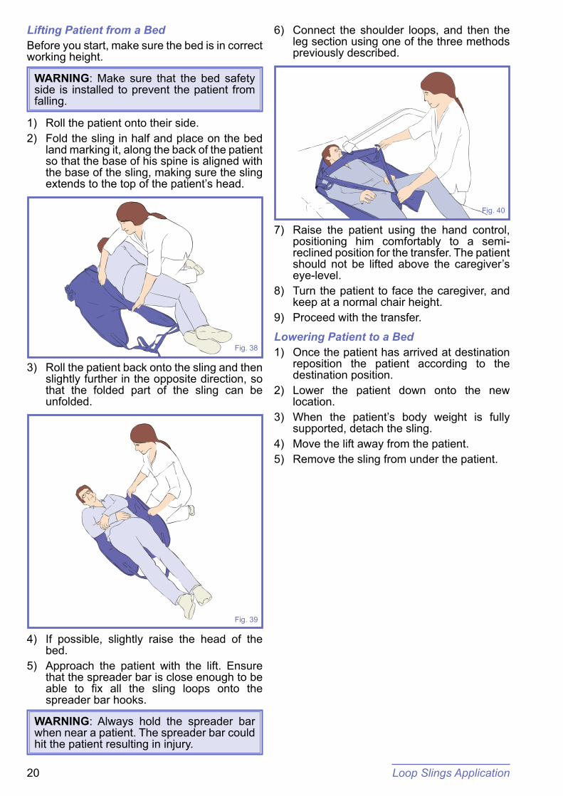
4) If possible, slightly raise the head of the bed.
5) Approach the patient with the lift. Ensure that the spreader bar is close enough to be able to fix all the sling loops onto the spreader bar hooks.
WARNING: Always hold the spreader bar when near a patient. The spreader bar could hit the patient resulting in injury.
6) Connect the shoulder loops, and then the leg section using one of the three methods previously described.
Fig. 40
7) Raise the patient using the hand control, positioning him comfortably to a semi-reclined position for the transfer. The patient should not be lifted above the caregiver’s eye-level.
8) Turn the patient to face the caregiver, and keep at a normal chair height.
9) Proceed with the transfer.
Lowering Patient to a Bed1) Once the patient has arrived at destination
reposition the patient according to the destination position.
2) Lower the patient down onto the new location.
3) When the patient’s body weight is fully supported, detach the sling.
4) Move the lift away from the patient.5) Remove the sling from under the patient.

Loop Slings Application 21
Lifting Patient from the FloorThe technique described here can be used for transferring patients lying on the floor. Patients being lifted from the floor due to a slip or fall should only be lifted after examination by qualified medical personnel. The patient can be lifted from a completely reclined position on the floor, but for his comfort, put a pillow under his head first. 1) Roll the patient onto their side.2) Fold the sling in half and place on the floor
land marking it, along the back of the patient so that the base of his spine is aligned with the base of the sling, making sure the sling extends to the top of the patient’s head.
Fig. 41
3) Roll the patient back onto the sling and then slightly further in the opposite direction, so that the folded part of the sling can be unfolded.
Fig. 42
4) Depending on circumstances, space or position of patient, approach the patient with the open part of the chassis.
5) Adjustment of the spreader bar height may have to be made before connection is possible.
6) Connect the shoulder loops, and then the leg section using one of the three methods previously described.
7) When all the connectors are securely attached, raise the patient from the floor in a semi-recumbent position.
8) Once raised from the floor, ensure the patient’s legs are clear of the chassis before continuing to lift.
Fig. 43
9) Turn the patient to face the caregiver, and keep at a normal chair height.
Lowering Patient to the Floor1) Lower the patient down onto the new
location.2) When the patient’s body weight is fully
supported, detach the sling.3) Move the lift away from the patient.4) Remove the sling from under the patient.

Care and Maintenance22
Care and MaintenanceCare and MaintenanceLift Cleaning and Care
Note: It is recommended that your Maxi 500 and its accessories are cleaned and disinfected between each patient use, or daily as a minimum. If the lift and equipment needs cleaning, or is suspected of being contaminated, follow the cleaning and disinfection procedures recommended below, before re-using the equipment.
For cleaning your lift and its accessories wipe down with a damp cloth using warm water to which a disinfectant / cleaner has been added (e.g. “Arjo” - disinfectant / cleaner or equivalent).
CAUTION: Never use a wet cloth on the control box, the battery support or the battery pack as it may cause corrosion on electrical components. If a hot air dryer is used to dry the lift, the temperature must not exceed 80°C (176°F.) Do not use petroleum based solvents or similar, as this may damage plastic parts.
When cleaning, pay special attention to parts that are most likely to be touched such as:
• the handset;• the control box;• the battery pack;• the lift handle;• the spreader bar.

Preventive Maintenance Schedule 23
Preventive Maintenance SchedulePreventive Maintenance ScheduleThe Maxi 500 is subject to wear and tear, and the following actions must be performed when specified to ensure that the product remains within its original manufacturing specification.
WARNING: The points on this checklist are the minimum the manufacturer recommends. In some cases more frequent inspections should be carried out. Continuing to use this equipment without conducting regular inspections will seriously compromise the user and resident / patient’s safety. Preventive maintenance specified in this manual can prevent accidents
WARNING: Safety related maintenance and authorized service must be carried out by qualified personnel, fully trained in servicing procedures by Arjo, and equipped with correct tools and proper documentation, including Parts List and Service Manual. Failure to meet these requirements could result in personal injuries and / or unsafe equipment
WARNING: Never proceed to maintenance or service while lift is in use with a patient.
POINTS TO BE INSPECTED BY USER / SERVICE TECHNICIAN
FREQUENCYAnnually (12 Hours*) Before every useInitially
1) When equipped with a 2-point spreader bar, ensure that the bar safety latches are present and are freely pivoting. x
2) Ensure that the battery charge indicator is within the normal range. x3) Ensure that the casters are firmly fixed to the chassis. x4) When equipped with a DPS, make sure that the DPS is properly attached with the pin and that
the pin is secured with the locking spring. x
5) Make sure that the mast is secured to the base with the locking screw. x6) Verify the proper functioning of the rear castor brakes. x x7) Ensure that the actuator attachments are tightened at both ends. x x8) Check front and rear castors regularly for hair and debris; clean when necessary. x9) Press the emergency stop button and make sure that all electrical power is cut off. No action
should occur when activating the “Up” or ‘Down” buttons. Hour meter and battery indicator should also shut down.
x x
10) Check all the functions on the hand control. Ensure that the hand control touch pad membrane is intact. x x
11) Check all the functions on the control box. x x12) Check the function of the emergency lowering device by applying weight to the lift and pulling the
red handle on the actuator. x x
* Time period indicated by the Hour meter.

Preventive Maintenance Schedule24
ADDITIONNAL POINTS TO BE INSPECTED BY SERVICE TECHNICIAN
FREQUENCYAnnually (12 Hours*)Before every useInitially
13) Make sure the shoulder bolt between the boom and the mast is securely fastened and that the cotter pin is present. x
14) Inspect all weld sites for cracking or separation. x15) Make sure that all nuts and locknuts of the base open / close mechanism are securely fastened
and the ball joints are in good condition. x
16) Check all bolts, nuts and locknuts to ensure they are tight. x17) Check if the leg pivot bolts are secured with locknuts; tighten, if necessary. x18) Make sure that the straight section of both legs is perpendicular to the base, in closed position. x19) If the product does not work as intended, immediately contact your local Arjo vendor for support. x20) Check that the Spreader Bar flange bushings, pivot bolt and welds are in good condition. x21) Check the condition of the friction discs and bushings of the DPS within the pivot points.
If found worn and/or damaged, parts must be replaced. x
22) When the friction discs and bushings of the DPS have been checked/replaced, reset friction assembly to support a 5.4 kg (12 lb) load at the handle. x
* Time period indicated by the Hour meter.

Troubleshooting 25
TroubleshootingTroubleshootingLift Trouble ResolutionHand control does not respond. • Check the red emergency stop button on the control box.
• Check the connector on hand control cord.• Check the battery condition (replace with a fully charged
battery pack).UP and DOWN buttons on control box do not respond.
• Check the red emergency stop button on the control box.• Check the battery condition (replace with a fully charged
battery pack).Actuator does not respond. • Check the red emergency stop button on control box.
• Check if the battery is installed correctly and fully charged. Test with a new, fully-charged battery pack.
• Check if the hand control is connected.• Check if control box is in automatic cut-out mode, make sure
boom is not obstructed or overloaded.Audible “beep” is heard from the control box.
• Battery is low. Replace with a freshly charged battery pack.
Actuator “stalls” during lift. • Battery is low. Replace with a freshly charged battery. Make sure not to exceed the lifting capacity.
Battery Trouble ResolutionYellow indicator light does not go off after several hours of charging time.
• Internal batteries need replacing. Call Arjo for replacement.
Battery pack indicates it is fully charged when in the charger, but when placed in the lift, will only do a few lifts.
• Replace the battery.*
(*) Generally, a humming noise coming from the actuator indicates low battery power.

Labels on the Lift26
Fig. 44
DUTY CYCLE:10% MAX, 2 min./18 min.
Conform to:ISO 10535AAMI ES60601-1CSA C22.2 #60601-1IEC60601-1/IEC60601-1-11CAN/CSA C22.2 No 601-1-M90 (SUP1+AM2)UL 60601-1
, 10A Max.
500lb / 227kgIP24
MAX. LOAD:24VRATING:
MAXI 500
Made in Canada
2012-12
ArjoHuntleigh ABVerkstadsvägen 5241 38 EslövSWEDEN
KM561091
KM56-XXXXX
S.W.L.227 kg500 lbs
Labels on the LiftLabels on the Lift
Product Name
Emergeny Stop /Reset Button
Safe Working Load (On Both Sides)
Battery Information
Product Identification Serial Number Manufacturer Data Manufactured Date
Operatingspecifications

Technical Specifications 27
Labels on the LiftLabels on the LiftPRODUCT INFORMATION MAXI 500 (KM56XXXX)
Total weight (without battery or accessory)
46,4 kg (102 lb)
Battery pack weight 5 kg (11 lb)Lifting capacity 227 kg (500 lb)
Minimum door requirement 700 mm (27.5 in)MECHANICAL
IP rating control lift Lift: Refer IP24 Hand Control : IPX7
Operating forces of controls Hand Control: < 5 N
Sound power level < 65 dBAELECTRICAL
Battery Type Rechargeable (Sealed Lead-Acid)
Battery Capacity 24V, 4AhBattery charger input (NDA8200): 100 to 240 Vac / 50-60 Hz / 50VA
Battery charger output 24 Vdc, 1A, 24VAProtection class Class II, double insulated
Up and down current limiting 10 A
Duty cycle 10%, 6 min / hour, 1 min continuousProtection against electrical shock Refer to product label
The Maxi 500 meets the requirements of Electromagnetic Compatibility (EMC) as stated in clause 12.5 of the Medical Devices Directive 93 / 42 / EEC.
The Maxi 500 is compliant to IEC 60601-1 series including applicable collateral standards and national deviations. The Maxi 500 is compliant to ISO 10535 standard.
WARNING: Portable RF communications equipment (including peripherals such as antenna cables and external antennas) should be used no closer than 30 cm to any part of the Maxi 500, including cables specified by the
manufacturer. Otherwise, performance degradation of this equipment could result. See “Electromagnetic Compatibility” section for more details.
ENVIRONMENTAL CONDITIONS
Ground Requirement Maximum Slope: 1° Surface condition: Flat hard surface
Ambient temperature range (lift, batteries)
Operation: 5° to 40°C (+41 to +104 F) Storage: - 25 to 70°C (-13 to 158F)
Relative humidity range Operation: 15 to 93%, non-condensing Storage: < 93%, non-condensing
Atmospheric pressure range Operation: 795 hPa to 1060 hPa (2000 m max) Storage: 500 hPa to 1060 hPa
WARNING: Product is not suitable in the presence of flammable anaesthetic mixture with air or oxygen, or with nitrous oxide.
SAFE DISPOSAL at END of LIFE
BatteryAll batteries in the product must be recycled separately. Batteries are to be disposed in accordance with national or local regulations. Sealed lead-acid, rechargeable, recyclable.
Package Wood and corrugated cardboard, recyclable.
ProductComponents that are primarily be made up of different kinds of metal (containing more than 90% metal by weight) for example spreader bars, rails, upright supports, etc., should be recycled as metals.
Electrical and electronic components
Lift systems having electrical & electronic components or an electrical cord should be disassembled & recycled per Waste of Electrical and Electronic Equipment (WEEE) or in accordance with local or national regulation.
Slings Slings including stiffeners/stabilisers, padding material, any other textiles or polymers or plastic materials etc. should be sorted as combustible waste.
Technical SpecificationsTechnical Specifications

Technical Specifications28
Dimensions
55 cm68 cm
70 cm95 cm
108 cm
Ø146 cmØ133 cm
55 cm
121 cm18 cm
55 cm
202 cm
130 cm
81 cm
32 cm
60 cm
132 cm
2.5 cm 12 cm
114 cm
CSP
48 cm
56 cm
25 cm
16 cm
DPS with Scale
DPS
2-Hook Spreader Bar with Scale
2-Hook Spreader Bar
Height of Accessories
CPS stands for Central Suspension Point: a reference point on the lift for measurements. On the Maxi 500 the CPS is the Accessory attachment point located at the boom end.
22 cm

Electromagnetic Compatibility 29
Electromagnetic ComplianceThe Maxi 500 has been tested for compliance with current regulatory standards regarding its capacity to block EMI (electromagnetic interference) from external sources.Nonetheless, some procedures can help reduce electromagnetic interferences:
• Ensure that other devices in patient-monitoring and / or life-support areas comply to accepted emissions standards.
• Maximize the distance between electro-medical devices. High-powered devices may produce EMI that can affect the floor lift.
For more information on how to manage the unit’s RF electromagnetic environment, please consult the AMI TIR 18-1997 - Guidance on Electromagnetic Compatibility of Medical Devices for Clinical / Biomedical Engineers.
WARNING: Use of accessories, cables and spare parts other than those specified or provided by Arjo could result in increased electromagnetic emissions or decreased electromagnetic immunity of this equipment and result in improper operation.
WARNING: Use of this equipment adjacent to or stacked with other equipment should be avoided because it could result in improper operation. If such use is necessary, this equipment and the other equipment should be observed to verify that they are operating normally.
WARNING: The equipment may cause radio interference or may disrupt the operation of nearby equipment. It may be necessary to take action, such as reorienting, relocating the equipment or shielding the location.
Electromagnetic EmissionsGuidance and Manufacturer’s Declaration -
Electromagnetic Emissions - For all Equipment and SystemsThe Maxi 500 is intended for use in the electromagnetic environment indicated below. The customer or the user of the Maxi 500 should assure that it is used in such an environment.
Emissions test Compliance Electromagnetic environment - guidance
RF emissions CISPR 11 Group 1
The Maxi 500 uses RF energy only for its internal function. Therefore, its RF emissions are very low and are
not likely to cause any interference in nearby electronic equipment.
RF emissions CISPR 11 Class B
The Maxi 500 is suitable for use in all establishments, including domestic establishments and those directly
connected to the public low-voltage power supply network that supplies buildings used for domestic purposes.
Electromagnetic CompatibilityElectromagnetic Compatibility

Electromagnetic Compatibility30
Electromagnetic ImmunityGuidance and Manufacturer’s Declaration -
Electromagnetic Immunity - For all Equipment and SystemsThe Maxi 500 is intended for use in electromagnetic environment specified below. The customer or the user of the Maxi 500 should assure that it is used in such an environment.
Immunity test IEC 60601 test level Compliance level Electromagnetic environment -
guidanceElectrostatic discharge
(ESD)IEC 61000-4-2
±8 kV contact±15 kV air
±8 kV contact±15 kV air
Floors should be wood, concrete or ceramic tile. If floors are
covered with synthetic material, the relative humidity should be at
least 30%.Electrical fast
transient / burstIEC 61000-4-4
±1 kV, I/O Ports100 kHz repetition
frequency
±1 kV, I/O Ports100 kHz repetition
frequency
Mains power quality should be that of a typical commercial or
hospital environment.
Power frequency (50 / 60 Hz)
magnetic field
IEC 61000-4-8
30 A/m50/60 Hz
30 A/m50/60 Hz
Power frequency magnetic fields should be at levels characteristic of a typical location in a typical
commercials or hospital environment.
NOTE: UT is the AC mains voltage prior to application of the test level.

Electromagnetic Compatibility 31
(continued)
Guidance and Manufacturer’s Declaration - Electromagnetic Immunity -For all Equipment and Systems
Immunity test IEC 60601 test level Compliance levelElectromagnetic
environment - guidance
Conducted RFIEC 61000-4-6
3 V outside ISM bandsbetween 0.15-80 MHz
6 V inside ISM and
amateur radio bandsbetween 0.15-80 MHz
3 V outside ISM bandsbetween 0.15-80 MHz
6 V inside ISM and
amateur radio bandsbetween 0.15-80 MHz
N/A
Radiated RFIEC 61000-4-3
10 V/m80 MHz to 2.7 GHz
10 V/m80 MHz to 2.7 GHz
N/A
Proximity fields from RF wireless communications
equipment
IEC 61000-4-3
380 - 390 MHz27 V/m; PM 50%; 18 Hz
430 - 470 MHz28 V/m; (FM ±5 kHz,
1 kHz sine) PM; 18 Hz
800 - 960 MHz28 V/m; PM 50%; 18 Hz
1700 - 1990 MHz28 V/m; PM 50%; 217 Hz
2400 - 2570 MHz28 V/m; PM 50%; 217 Hz
5100 - 5800 MHz9 V/m; PM 50%; 217 Hz
704 - 787 MHz9 V/m; PM 50%; 217 Hz
380 - 390 MHz27 V/m; PM 50%; 18 Hz
430 - 470 MHz28 V/m; (FM ±5 kHz,
1 kHz sine) PM; 18 Hz
800 - 960 MHz28 V/m; PM 50%; 18 Hz
1700 - 1990 MHz28 V/m; PM 50%; 217 Hz
2400 - 2570 MHz28 V/m; PM 50%; 217 Hz
5100 - 5800 MHz9 V/m; PM 50%; 217 Hz
704 - 787 MHz9 V/m; PM 50%; 217 Hz
N/A

Electromagnetic Compatibility32
Intentionally left blank

Intentionally left blank

Intentionally left blank

AUSTRALIAArjo AustraliaBuilding B, Level 311 Talavera RoadMacquarie Park, NSW, 2113, AustraliaPhone: 1800 072 040
BELGIQUE / BELGIËArjo Belgium nvEvenbroekveld 169420 Erpe-MereBelgiumT: +32 (0) 53 60 73 80F: +32 (0) 53 60 73 81E-mail: [email protected]
BRASILArjo Brasil Equipamentos Médicos LtdaRua Marina Ciufuli Zanfelice, 329 PB02 Galpão - LapaSão Paulo – SP – BrasilCEP: 05040-000Phone: 55-11-3588-5088E-mail: [email protected]: [email protected]
CANADAArjo Canada Inc.90 Matheson Boulevard WestSuite 300CA-MISSISSAUGA, ON, L5R 3R3Tel/Tél: +1 905 238 7880Free: +1 800 665 4831 InstitutionalFree: +1 800 868 0441 Home CareFax: +1 905 238 7881E-mail: [email protected]
ČESKÁ REPUBLIKAArjo Czech Republic s.r.o.Na Strzi 1702/65140 00 PrahaCzech RepublicPhone No: +420225092307e-mail: [email protected]
DANMARKArjo A/SVassingerødvej 52DK-3540 LYNGETel: +45 49 13 84 86Fax: +45 49 13 84 87E-mail: [email protected]
DEUTSCHLANDArjo GmbHPeter-Sander-Strasse 10DE-55252 MAINZ-KASTELTel: +49 (0) 6134 186 0Fax: +49 (0) 6134 186 160E-mail: [email protected]
ESPAÑAArjo Ibérica S.L.Parque Empresarial Rivas Futura, C/Marie Curie 5Edi cio Alfa Planta 6 o cina 6.1-.62ES-28521 Rivas Vacia, MADRIDTel: +34 93 583 11 20Fax: +34 93 583 11 22E-mail: [email protected]
FRANCE Arjo SAS2 Avenue Alcide de GasperiCS 70133FR-59436 RONCQ CEDEXTél: +33 (0) 3 20 28 13 13Fax: +33 (0) 3 20 28 13 14E-mail: [email protected]
HONG KONG Arjo Hong Kong LimitedRoom 411-414, 4/F, Manhattan Centre,8 Kwai Cheong Road, Kwai Chung, N.T.,HONG KONGTel: +852 2960 7600Fax: +852 2960 1711
ITALIAArjo Italia S.p.A.Via Giacomo Peroni 400-402IT-00131 ROMATel: +39 (0) 6 87426211Fax: +39 (0) 6 87426222E-mail: [email protected]
MIDDLE EASTArjo Middle East FZ-LLCOf ce 908, 9th Floor, HQ Building,North Tower,Dubai Science Park, Al Barsha SouthP.O Box 11488, Dubai, United Arab EmiratesDirect +971 487 48053Fax +971 487 48072Email: [email protected]
NEDERLANDArjo BVBiezenwei 214004 MB TIELPostbus 61164000 HC TIELTel: +31 (0) 344 64 08 00Fax: +31 (0) 344 64 08 85E-mail: [email protected]
NEW ZEALANDArjo Ltd34 Vestey DriveMount WellingtonNZ-AUCKLAND 1060Tel: +64 (0) 9 573 5344Free Call: 0800 000 151Fax: +64 (0) 9 573 5384E-mail: [email protected]
NORGEArjo Norway ASOlaf Helsets vei 5N-0694 OSLOTel: +47 22 08 00 50Faks: +47 22 08 00 51E-mail: [email protected]
ÖSTERREICHArjo GmbHLemböckgasse 49 / Stiege A / 4.OGA-1230 WienTel: +43 1 8 66 56Fax: +43 1 866 56 7000
POLSKAArjo Polska Sp. z o.o.ul. Ks Piotra Wawrzyniaka 2 PL-62-052 KOMORNIKI (Poznań)Tel: +48 61 662 15 50Fax: +48 61 662 15 90E-mail: [email protected]
PORTUGALArjo em PortugalMAQUET Portugal, Lda. (Distribudor Exclusivo)Rua Poeta Bocage n.º 2 - 2G PT-1600-233 LisboaTel: +351 214 189 815Fax: +351 214 177 413E-mail: [email protected]
SUISSE / SCHWEIZArjo AG Fabrikstrasse 8PostfachCH-4614 HÄGENDORFTél/Tel: +41 (0) 61 337 97 77Fax: +41 (0) 61 311 97 42
SUOMIArjo Scandinavia ABRiihitontuntie 7 C02200 EspooFinlandPuh: +358 9 6824 1260E-mail: Asiakaspalvelu. [email protected]
SVERIGEArjo International HQHans Michelsensgatan 10SE-211 20 MALMÖTel: +46 (0) 10 494 7760Fax: +46 (0) 10 494 7761E-mail: [email protected]
UNITED KINGDOMArjo UK and IrelandHoughton Hall ParkHoughton RegisUK-DUNSTABLE LU5 5XFTel: +44 (0) 1582 745 700Fax: +44 (0) 1582 745 745E-mail: [email protected]
USAArjo Inc.2349 W Lake Street Suite 250US-Addison, IL 60101Tel: +1 630 307 2756Free: +1 80 0 323 1245 InstitutionalFree: +1 800 868 0441 Home CareFax: +1 630 307 6195E-mail: [email protected]
JAPANArjo Japan K.K.東京都港区虎ノ門三丁目7番8号 ランディック第2虎ノ門ビル9階電話:+81 (0)3-6435-6401
Address page - REV 25: 01/2020
www.arjo.com

At Arjo, we are committed to improving the everyday lives of people affected by reduced mobility and age-related health challenges. With products and solutions that ensure ergonomic patient handling, personal hygiene, disinfection, diagnostics, and the effective prevention of pressure ulcers and venous thromboembolism, we help professionals across care environments to continually raise the standard of safe and dignified care. Everything we do, we do with people in mind.
ArjoHuntleigh ABHans Michelsensgatan 10 211 20 Malmö, Swedenwww.arjo.com