Embed Size (px)
Citation preview
1
Instructions for HD-17 / HD-20 PowerGlide™
13655 Stowe Dr., Poway, Ca. 92064
Model #
Serial #
Form # ADM-HD1720
6-11
Please read before use.
Register your productat www.mytee.com/help
Set up p. 3 General information p. 5 Parts & pricing p. 8 Wiring diagram p. 10 Notes p.11

2

3
BACK
POWER TRIGGERS
While holding the safety switch lock in disengaged position, squeeze power triggers to operate machine. To stop the machine, simply release the triggers.
SAFETY SWITCH
FRONT
1. Safety Switch2. Handle Adjustment Lever3. Cord Storage Hook 4. Wheels
5. Power Triggers 6. Power Cord 7. Chrome Plated Motor
3
1
2
To turn the machine on, the operation handle must be lowered to the operating position before switching the machine ON. Disengage the safety switch lock by pushing it forward with either thumb.
4
5
6
7
HD17 / HD20 POWERGLIDE™
4
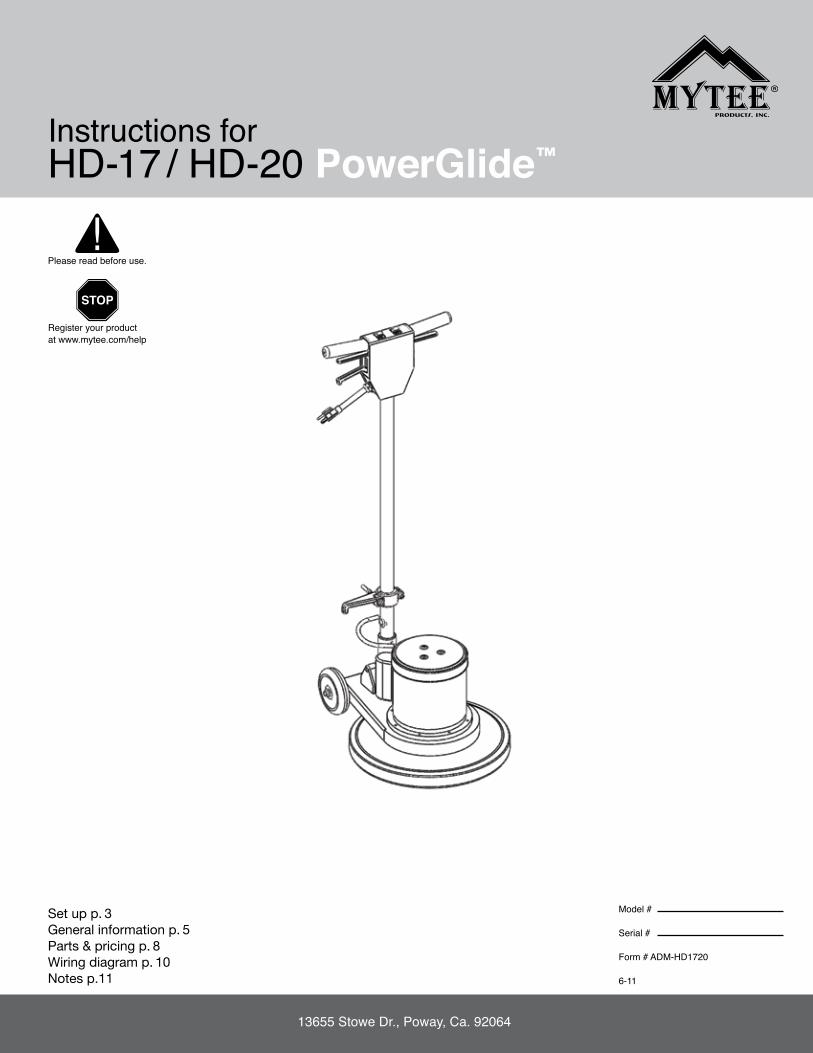
POSITION GEAR ADjuSTmENT HEIGHT LEVER
The handle can be adjusted to any desired working position by simply squeezing the adjustment lever. Move the handle to the desired position, then release adjustment lever locking handle in place.
Once you release adjustment height lever, handle will lock on to gear.
When not in use, loosely wind the power cord around the cord storage hook on the handle shaft and handle grip.
Note: Disconnect the power cord from electrical outlet before installing a brush or pad driver. ON - Push the brush or pad driver firmly in position, then turn it counter-clockwise until it locks into place. REMOVE - Turn clockwise until it stops, then lift off.
ON OFF
BRuSH AND PAD DRIVER INSTALLATION CORD STORAGE HOOK
HD17 / HD20 POWERGLIDE™

5
Dear Customer: Congratulations on the purchase of your new HD-17/20. As you are already aware, the scene of the equipment world is becoming more high tech, and we at Mytee Products Inc. strive to keep you on the cutting edge with superior quality and technology. Keep in mind that the HP-17/20 is a machine, so neglect or abuse will cause unnecessary damage and void the warranty. However with simple maintenance the HP-17/20 will give quality performance for many years to come. If warranty questions arise, please consult your user manual or get in touch with your distributor. If you have questions about maintenance, replacing parts or ordering parts, please call an authorized Mytee Products Inc. Service Center. To see an updated list, visit our website at www.mytee.com. Before you begin using your new machine, please read your manual thoroughly. Sincerely, Mytee Customer Care Dept. Grounding InstructionsThis machine must be grounded. If it should malfunction or breakdown, grounding provides a path of least resistance for electrical shock. This machine is equipped with a cord having an equipment-grounding conductor and grounding plug. The plug must be plugged into an appropriate outlet that is properly installed in accordance with all local code and ordinances. Do not remove ground pin; if missing, replace plug before use. Improper connection of the equipment-grounding conductor can result in a risk of electric shock. Check with a qualified electrician or service person if you are in doubt as to whether the outlet is properly grounded. Do not modify the plug provided with the machine. If it will not fit the outlet, have a proper outlet installed by a qualified electrician. This appliance is for use on a nominal 120-volt circuit, and has a grounding plug that looks like the plug illustrated in Figure 1 below. A temporary adapter illustrated in Figures 2 and 3 may be used~to connect this plug to a 2-pole receptacle as shown in Figure 2 if a properly grounded outlet is not available. The temporary adapter should be used only until a properly grounded outlet (Figure 1) can be installed by a qualified electrician. The green colored rigid ear, tab or the like extending from the adapter must be connected to a permanent ground such as a properly grounded outlet box cover. Whenever the adapter is used, it must be held in place by a metal screw. Grounding adapters are not approved for use in Canada. Replace the plug if the grounding pin is damaged or broken. The Green (or GreenYellow) wire in the cord is the grounding wire. When replacing a plug, this wire must be attached to the grounding pin only. DO NOT use extension cords. Please Note for America use only Parts and ServiceRepairs, when required, should be performed by Mytee service personnel or Mytee authorized Service Center using Mytee original replacement parts and accessories. Call Mytee for repair parts or service. Please specify the Model and Serial Number when discussing your machine. Name PlateThe Model and Serial Number of your machine are shown on the Nameplate on the back panel of the machine. This information is needed when ordering repair parts for the machine. Use the space provided on the front cover to note the Model and Serial Number of your machine for future reference.
unpacking the machine When the machine is delivered, carefully inspect the shipping carton and the machine for damage. If damage is evident, save the shipping carton so that it can be inspected by the carrier that delivered it. Contact the carrier immediately to file a freight damage claim. Caution and WarningsSymbolsMytee uses the symbols below to signal potentially dangerous conditions. Always read this information carefully and take the necessary steps to protect personnel and property. Is used to warn of immediate hazards that will cause severe personal injury or death. Is used to call attention to a situation that could cause severe personal injury. Is used to call attention to a situation that could cause minor personal injury or damage to the machine or other property. When using an electrical appliance, basic precautions should always be followed, including the following: Read all instructions before using this machine. This product is intended for commercial use only. To reduce the risk of fire, electrical shock, or injury:1. Read all instructions before using equipment. 2. Use only as described in this manual. Use only manufacturer’s recommended attachments. 3. Your floor machine is equipped with a safety switch lock and power switch triggers designed for your safety. Do not attempt to bypass or defeat the safety switch lock. Never use any device to lock the power switch triggers in the “ON” position. 4. Always unplug power cord from electrical outlet before attempting any adjustments or repairs. 5. Use care to keep the electrical supply cord from contacting the rotating brush or drive block. 6. Do not unplug by pulling on cord. To unplug, grasp the plug, not the cord. 7. Do not pull or carry by cord. Do not close a door on cord or pull cord around sharp edges or corners. 8. Connect to properly grounded (3-wire) outlet only refer to grounding instructions. 9. Do not run appliance over cord. Keep cord away from heated surfaces. 10. Do not use with damaged cord or plug. If cord is damaged, repair immediately. 11. Turn off all controls before unplugging. 12. Do not use outdoors. 13. Always unplug or disconnect the appliance from power supply when not in use. 14. Do not handle the plug or floor machine with wet hands. 15. Do not allow to be used as a toy. Close attention is necessary when used by or near children. 16. Wind the cord no tighter than is necessary to retain it during storage. 17. Do not use in areas where flammable or combustible material may be present. 18. Do not leave the unit exposed to harsh weather elements. Temperatures below freezing may damage components and void warranty. 19. Use only the appropriate handles to move and lift unit. Do not use any other parts of this machine for this purpose. 20. Keep hair, loose clothing, fingers, and all parts of the body away from all openings and moving parts. 21. Use extra care when working near stairs. 22. To reduce the risk of fire or electric shock, do not use this machine with a solid-state speed control device. 23. The voltage and frequency indicated on the name plate must correspond to the wall receptacle supply voltage. 24. When cleaning and servicing the machine, local or national regulations may apply to the safe disposal of liquids which may contain: chemicals, grease, oil, acid, alka-lines, or other dangerous liquids. 25. Store your floor machine indoors in a cool, dry area. 26. Keep your work area well lit. 27. Do not leave operating unattended. Use of flammable chemicals could cause explosion, fire, and death.
Figure 1
Grounding Pin
Grounded Outlet
Grounded Outlet Box
Adapter
Tab for Grounding Screw
Metal Screw
Figure 2 Figure 3
GENERAL INFORmATION
6
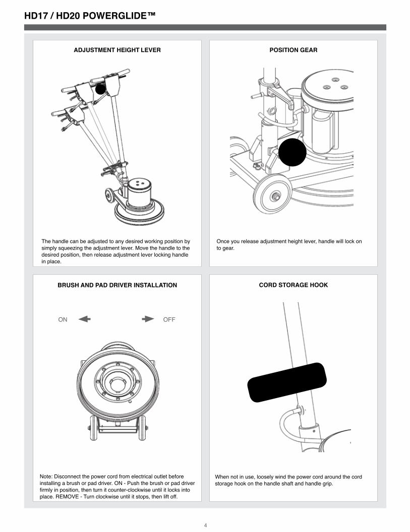
Controls 1. The ON/OFF switch is conveniently located in the form of dual triggers underneath the handle grips. 2. To turn the machine on, the operation handle must be lowered to the operating position before switching the machine ON. 3. Do not apply pressure on the triggers before the safety switch lock is disengaged. 4. Disengage the safety switch lock by pushing it forward with either thumb. Then, while holding the safety switch lock in disengaged position, squeeze the power trig-gers toward the handle grips and return your thumb to the handle grip. 5. To stop the machine, simply release the triggers. The safety switch lock will auto-matically return to the engaged position. Brush and Pad Driver Setup 1. Disconnect the power cord from the electrical outlet before installing a brush or pad driver. 2. To install a brush or pad driver, leave the handle in the upright position and tip the machine backwards so it rests on its wheels and upper handle section. 3. Align the cut-outs on the inner ring of the brush or pad driver with the tabs on the inside of the ring of the drive hub.4. Push the brush or pad driver firmly in position.5. Turn it counter-clockwise until it locks into place.6. Return machine to upright position.7. To remove, turn brush or pad driver clockwise until it stops, then lift it off. 8. Always remove the brush or pad driver when the machine is not in use. Handle Operation 1. Squeeze Adjustment Height lever. 2. Pivot handle to desired position. 3. Release lever. Pre-Operation 1. Vacuum carpet and upholstery and remove other debris. 2. Perform machine setup procedures. 3. Inspect power cord for damage. Operation 1. Squeeze the Adjustment Height lever.2. Pivot handle to desired position.3. Release lever.4. Place both hands firmly on the handle grips with your fingers around the power triggers. Do not apply pressure on the triggers before the safety lock is disengaged.5. Disengage the ambidextrous safety switch lock by pushing it forward with your thumb.6. While holding the safety switch lock forward, squeeze the power triggers and remove your thumb from the safety switch lock.7. To stop the machine, simply release the triggers. The safety switch lock will auto-matically return to the engaged position. 1. Work away from outlet and power cord to prevent cord damage. 2. To clean heavily soiled areas, repeat cleaning path from different direction. Guidelines1. For ease of operation, always keep the brush or pad surface level, balanced, and flat on the floor at all times.2. Always adjust the operating handle to a comfortable height at which the brush or pad surface is balanced before starting the machine.3. Your floor machine will operate differently on various surfaces. There will be more resistance when the machine is used with a brush on carpet than when it is used with a pad on a smooth surface.4. To move the machine to the right, apply slight upward pressure on the handle.5. To move the machine to the left, apply slight downward pressure on the handle.6. To move the machine forward or backward, push or pull in the desired direction, keeping the pad or brush level on the floor at all times. After use 1. Unplug. 2. Inspect hoses and replace if damaged. 3. Loosely wind up the power cord around the handle bar and the hook at the bottom of the shaft. 4. After each use, wipe your floor machine with a clean, soft, damp cloth.5. Store in a clean, dry place. 6. Do not expose to rain. Store indoors.
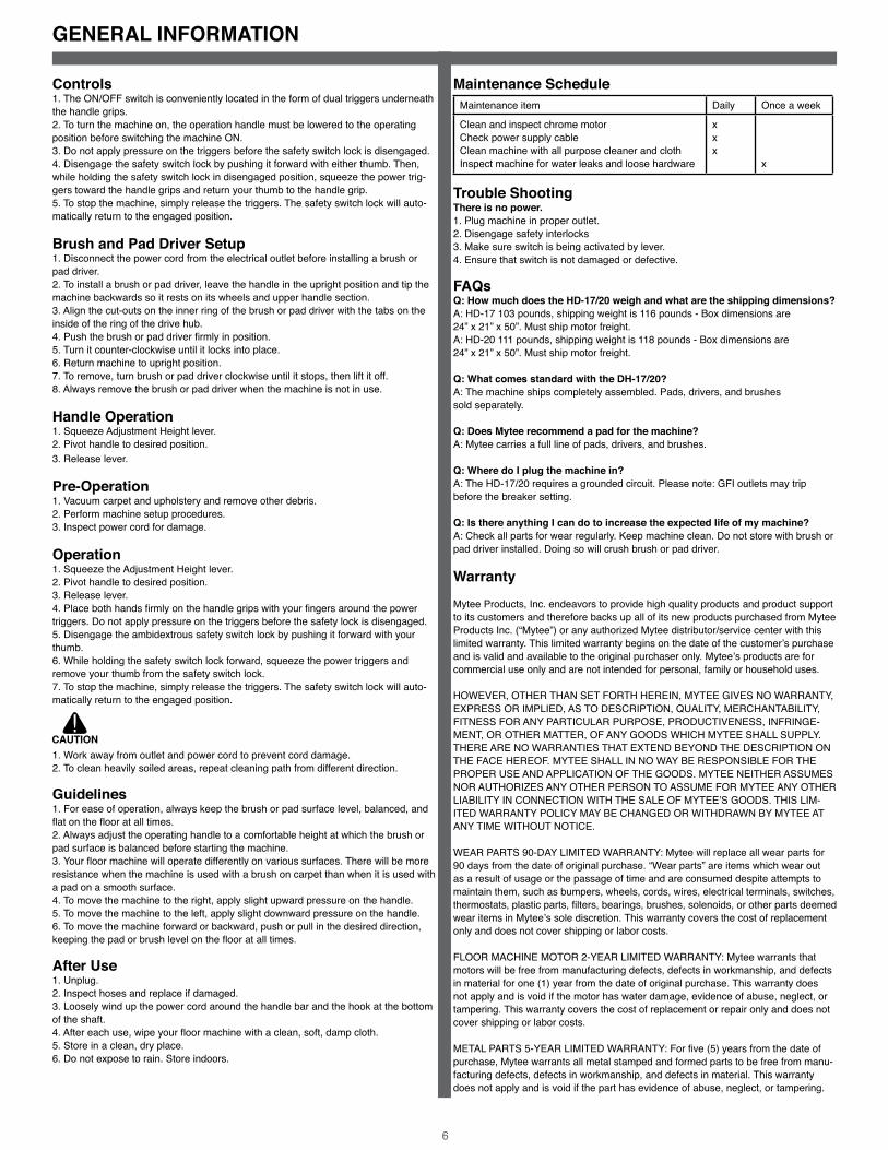
maintenance Schedule Maintenance item Daily Once a week
Clean and inspect chrome motor Check power supply cable Clean machine with all purpose cleaner and cloth Inspect machine for water leaks and loose hardware
x x x
x Trouble Shooting There is no power.1. Plug machine in proper outlet.2. Disengage safety interlocks 3. Make sure switch is being activated by lever. 4. Ensure that switch is not damaged or defective. FAQs Q: How much does the HD-17/20 weigh and what are the shipping dimensions?A: HD-17 103 pounds, shipping weight is 116 pounds - Box dimensions are 24” x 21” x 50”. Must ship motor freight.A: HD-20 111 pounds, shipping weight is 118 pounds - Box dimensions are 24” x 21” x 50”. Must ship motor freight.
Q: What comes standard with the DH-17/20?A: The machine ships completely assembled. Pads, drivers, and brushes sold separately.
Q: Does mytee recommend a pad for the machine?A: Mytee carries a full line of pads, drivers, and brushes. Q: Where do I plug the machine in?A: The HD-17/20 requires a grounded circuit. Please note: GFI outlets may tripbefore the breaker setting.
Q: Is there anything I can do to increase the expected life of my machine?A: Check all parts for wear regularly. Keep machine clean. Do not store with brush or pad driver installed. Doing so will crush brush or pad driver. Warranty Mytee Products, Inc. endeavors to provide high quality products and product support to its customers and therefore backs up all of its new products purchased from Mytee Products Inc. (“Mytee”) or any authorized Mytee distributor/service center with this limited warranty. This limited warranty begins on the date of the customer’s purchase and is valid and available to the original purchaser only. Mytee’s products are for commercial use only and are not intended for personal, family or household uses.
HOWEVER, OTHER THAN SET FORTH HEREIN, MYTEE GIVES NO WARRANTY, EXPRESS OR IMPLIED, AS TO DESCRIPTION, QUALITY, MERCHANTABILITY, FITNESS FOR ANY PARTICULAR PURPOSE, PRODUCTIVENESS, INFRINGE-MENT, OR OTHER MATTER, OF ANY GOODS WHICH MYTEE SHALL SUPPLY. THERE ARE NO WARRANTIES THAT EXTEND BEYOND THE DESCRIPTION ON THE FACE HEREOF. MYTEE SHALL IN NO WAY BE RESPONSIBLE FOR THE PROPER USE AND APPLICATION OF THE GOODS. MYTEE NEITHER ASSUMES NOR AUTHORIZES ANY OTHER PERSON TO ASSUME FOR MYTEE ANY OTHER LIABILITY IN CONNECTION WITH THE SALE OF MYTEE’S GOODS. THIS LIM-ITED WARRANTY POLICY MAY BE CHANGED OR WITHDRAWN BY MYTEE AT ANY TIME WITHOUT NOTICE.
WEAR PARTS 90-DAY LIMITED WARRANTY: Mytee will replace all wear parts for 90 days from the date of original purchase. “Wear parts” are items which wear out as a result of usage or the passage of time and are consumed despite attempts to maintain them, such as bumpers, wheels, cords, wires, electrical terminals, switches, thermostats, plastic parts, filters, bearings, brushes, solenoids, or other parts deemed wear items in Mytee’s sole discretion. This warranty covers the cost of replacement only and does not cover shipping or labor costs.
FLOOR MACHINE MOTOR 2-YEAR LIMITED WARRANTY: Mytee warrants that motors will be free from manufacturing defects, defects in workmanship, and defects in material for one (1) year from the date of original purchase. This warranty does not apply and is void if the motor has water damage, evidence of abuse, neglect, or tampering. This warranty covers the cost of replacement or repair only and does not cover shipping or labor costs.
METAL PARTS 5-YEAR LIMITED WARRANTY: For five (5) years from the date of purchase, Mytee warrants all metal stamped and formed parts to be free from manu-facturing defects, defects in workmanship, and defects in material. This warranty does not apply and is void if the part has evidence of abuse, neglect, or tampering.
GENERAL INFORmATION
7
This warranty covers the cost of replacement or repair only and does not cover ship-ping or labor costs.
LIMITATION OF DAMAGES: THE REMEDY OF REPLACEMENT OR REPAIR OF ANY DEFECTIVE GOODS SHALL BE THE EXCLUSIVE REMEDY UNDER ANY WARRANTY MADE BY MYTEE, WHETHER EXPRESS OR IMPLIED. IN NO EVENT SHALL MYTEE BE LIABLE FOR ANY INCIDENTAL OR CONSEQUENTIAL DAMAGES, PROPERTY DAMAGES, OR PERSONAL INJURIES.
All limited warranties are void for, and Mytee does not warrant in any way, any prod-uct that evidences misapplication, improper installation, abuse, lack of maintenance, negligence in use or care, abnormal use, alteration of design, use of incompatible or corrosive chemicals, use in a rental service, and/or servicing, installation of parts, or repairs by anyone other than Mytee or a Mytee authorized distributor or service cen-ter. Mytee may make changes in products it manufactures and markets at any time; these change are made without obligation to change, retrofit, or upgrade any product previously sold or manufactured.
Mytee has no obligation to honor the limited warranties set forth herein unless the original purchaser, promptly upon discovering the warranty claim and prior to continu-ing to use the product, contacts Mytee or a Mytee authorized distributor or service center to describe the claim and to receive and follow instructions for documenting and resolving the claim. In addition, the purchaser must provide the product to which the claim applies to Mytee or a Mytee authorized distributor or service center for a thorough inspection.
If any provision or portion of this limited warranty policy is found to be unenforceable, then the remaining provisions and portions shall remain valid and enforceable. If any provision or portion of this limited warranty policy is found to be limited by law, then that provision or portion shall be construed to make it effective within the bounds of law. For example, if there are legal limitations on the duration of warranties, the warranties made herein shall be construed to have the minimum duration required by law, or, if there are legal limitations of exclusion of remedies, the exclusions made herein shall be construed to apply to the fullest extent possible without violating the law. The validity, construction and performance of this warranty policy shall be governed by the laws of the State of California, without respect to conflicts of laws principles. The exclusive jurisdiction of any legal action arising from or related to this warranty policy shall be in the State of California and no legal action shall be commenced elsewhere.
Return material Authorization Procedure It is the responsibility of any Authorized Service Center (ASC) or Distributor with written authorization to ensure the Customers equipment is repaired as soon as possible. Only Mytee Products Inc. or it’s authorized dealers with written authoriza-tion, service centers, and agents may make warranty repairs on these products. All others do so at their own risk and expense. The Distributor must follow Mytee Products, Inc. standard RMA procedure: 1. When a repair falls within the Warranty time period for a piece of equipment, the Distributor will fill out a RMA/Warranty claim form. This form will act as a repair order to replace any defective parts. 2. All defective parts must be returned to Mytee Products, Inc. with the RMA/claim form for evaluation at the customer’s expense. This shipping is non-refundable. All warranty claims are subject to an evaluation by Mytee Products, Inc. to determine if warranty will be approved. Any credit for repair and/or parts will only be issued upon evaluation and approval from Mytee Products, Inc. 3. When Warranty is approved, the Distributor’s account will be credited for the replacement part(s). Mytee Products, Inc. will ship the warranted replacement part(s) to the Distributor prepaid. If Warranty is denied the Distributor’s account will not be credited for any parts sent for this claim.
GENERAL INFORmATION

8
20" V
ERSI
ON
:
REVI
SIO
NS
REV.
DES
CRIP
TIO
ND
ATE
APP
ROVE
D
OD
OR
IGIN
AL
DR
AFT
7/22
/200
9JF
L
ITEM
NO
.PA
RT N
O.
DES
CRIP
TIO
NQ
TY.
1H
169
bo
lt, 1
/4-2
0 x
2", h
ex
he
ad
8
2H
213
wa
she
r, 1/
4" lo
ck,
s/s
18
3H
210
wa
she
r, 1/
4" fl
at,
s/s
84
G03
2b
um
pe
r, 17
", flo
or m
ac
hin
e1
5H
608
be
ll h
ou
sing
, 17"
1
6P5
40sp
ac
er,
be
ll h
ou
sing
/ch
ass
is8
7H
848
ch
ass
is, fl
oo
r ma
ch
ine
1
8C
314
mo
tor,
1.5
HP,
60H
Z, 1
20/2
40 V
1
9H
143
mo
tor c
ove
r, flo
or m
ac
hin
e1
10H
230
scre
w, 1
0-32
x 1
/2 p
hil
pa
n6
11H
841
sup
po
rt, p
ivo
t, fl
oo
r ma
ch
ine
2
12H
702
roll
pin
,1 3
/4" x
1/2
", p
ivo
t, fl
oo
r ma
ch
ine
2
13H
341
ha
nd
le p
ivo
t, fl
oo
r ma
ch
ine
1
14H
705
bo
lt, g
uid
e, l
oc
kin
g p
isto
n1
15H
847
bu
shin
g, l
oc
kin
g p
isto
n1
16H
152
reta
inin
g ri
ng
, in
tern
al 1
1/2
"1
17H
157
sprin
g, h
an
dle
ad
just
me
nt
1
18H
844
loc
kin
g p
isto
n, h
an
dle
ad
j.1
19H
151
bo
lt, 5
/16-
18 x
3/4
" Lo
ng
SH
CS
10
20H
843
loc
kin
g a
rc, h
an
dle
ad
j, flo
or m
ac
hin
e1
21H
153
co
tto
r pin
, 1 1
/2" x
5/3
2"1
22H
340
axl
e, 1
2.25
" x .5
0" d
ia1
23H
427
wa
she
r, w
ave
, 580
6-60
-34
24H
212
wa
she
r, 9/
16"id
x 1
"od
, fla
t, s
/s2
25H
170
wh
ee
l, 5"
226
H21
9c
ap
, axl
e, 1
/2"
2
27H
148
wa
she
r, 5/
16",
na
rro
w8
28
H15
9c
ab
le, h
an
dle
ad
j, flo
or m
ac
hin
e1
29H
273
nu
t, k
ep
, #10
-32
zin
c2
30H
916
clip
, co
rd, 5
/16"
, nyl
on
1
31H
144
stra
in re
lief,
po
we
r co
rd, f
loo
r ma
ch
ine
1
32E7
8950
' 14/
3 Ex
ten
sion
co
rd -
Ye
llow
1
33H
149
bo
lt, 5
/16
shld
r x 5
/8" w
/ 1/
4-20
th
rd1
34P5
29sp
ac
er,
leve
r, h
an
dle
ad
j.1
35H
216
nu
t, lo
ck,
1/4
-20,
nyl
on
inse
rt, s
/s1
36H
839
leve
r, h
an
dle
ad
j., fl
oo
r ma
ch
ine
1
37H
167
switc
h, f
loo
r ma
ch
ine
1
38H
211
wa
she
r, 1/
4"id
x 1
"od
, fla
t, s
/s1
39H
275
6-32
x 3
/16
p-p
an
inte
rna
l se
m z
inc
1
40H
166
insu
latio
n, s
witc
h, f
loo
r ma
ch
ine
1
41H
855
leve
r, sw
itch
, flo
or m
ac
hin
e1
42H
160
sprin
g, s
witc
h/l
eve
r2
43G
040
grip
, ha
nd
le, f
loo
r ma
ch
ine
2
44P5
41lo
cko
ut,
flo
or m
ac
hin
e1
45H
161
roll
pin
, 1 3
/4" x
1/8
", flo
or m
ac
hin
e2
46H
610
switc
h c
ove
r flo
or m
ac
hin
e1
47H
168
sprin
g, l
oc
kou
t, fl
oo
r ma
ch
ine
1
48H
215
nu
t, h
ex,
1/4
-20
s/s
1
49P5
24p
lug
, pla
stic
, flo
or m
ac
hin
e h
an
dle
1
50H
231
scre
w, 1
0-32
x 1
" ph
oil
pa
n1
51H
849
ha
nd
le, f
loo
r ma
ch
ine
1
52H
165
co
rd, h
oo
k, fl
oo
r ma
ch
ine
153
H15
0b
olt,
5/1
6-18
x 1
1/4
" lo
ng
SC
HS
2
54H
164
gro
mm
et,
flo
or m
ac
hin
e, 3
/16"
gro
ove
1
PART
N
O.
DES
CRIP
TIO
NQ
TY.
REPL
ACE
S
G04
1b
um
pe
r, 20
", flo
or m
ac
hin
e1
G03
2 (#
4)
H60
9b
ell
ho
usin
g, 2
0"1
H60
8 (#
5)
D C B
ABCD
12
34
56
788
76
54
32
1
EF
EF
HD
-17
SHEE
T 1
OF
2
17" F
loo
r Ma
chi
ne.
115V
. Im
pe
rial m
oto
r (#
AD
1501
9C)
5/20
10
OD
SCA
LE: 1
:8
REV
DW
G.
NO
.
CSIZE
TITL
E:
NA
ME
DA
TE
CH
ECKE
D
DRA
WN
PRO
PRIE
TARY
AN
D C
ON
FID
ENTI
AL
A
DO
NO
T SC
ALE
DRA
WIN
G
858-
679-
1191
mytee
PR
OD
UC
TS, I
NC
.J.
Ca
sh
THE
INFO
RMA
TIO
N C
ON
TAIN
ED IN
TH
ISD
RAW
ING
IS T
HE
SOLE
PRO
PERT
Y O
FM
YTEE
PRO
DU
CTS
, IN
C.
AN
Y RE
PRO
DU
CTI
ON
IN P
ART
OR
AS
A W
HO
LEW
ITH
OU
T TH
E W
RITT
EN P
ERM
ISSI
ON
OF
MYT
EE P
ROD
UC
TS, I
NC
. IS
PRO
HIB
ITED
.
HD17 / HD20 POWERGLIDE™ PARTS & PRICING

9
45
7
8
25
26
20
181615
1411
12
51
33
27
36
37
41
45
44
28
5227
53
1
23
43
38
42
10
34
10
47
27
2 196
19 2
23
40
3231
To H
341
(#13
)
To H
849
(#52
)
13
30
9
10
To H
159
(#28
)
To H
844
(#18
)
46
2
1950
48
17
43
54
2229
21
35
49
39
29
24
23
D C B
ABCD
12
34
56
788
76
54
32
1
EF
EF
HD
-17
SHEE
T 2
OF
2
17" F
loo
r Ma
chi
ne.
115V
. Im
pe
rial m
oto
r (#
AD
1501
9C)
5/20
10
OD
SCA
LE: 1
:8
REV
DW
G.
NO
.
CSIZE
TITL
E:
NA
ME
DA
TE
CH
ECKE
D
DRA
WN
PRO
PRIE
TARY
AN
D C
ON
FID
ENTI
AL
A
DO
NO
T SC
ALE
DRA
WIN
G
858-
679-
1191
mytee
PR
OD
UC
TS, I
NC
.J.
Ca
sh
THE
INFO
RMA
TIO
N C
ON
TAIN
ED IN
TH
ISD
RAW
ING
IS T
HE
SOLE
PRO
PERT
Y O
FM
YTEE
PRO
DU
CTS
, IN
C.
AN
Y RE
PRO
DU
CTI
ON
IN P
ART
OR
AS
A W
HO
LEW
ITH
OU
T TH
E W
RITT
EN P
ERM
ISSI
ON
OF
MYT
EE P
ROD
UC
TS, I
NC
. IS
PRO
HIB
ITED
.
HD17 / HD20 POWERGLIDE™ PARTS & PRICING

10
L 1
L 2
GND
Cord Input Primary
Black
Bla
ck
Bla
ck
White
Whi
te
Gre
en
C315
Green
Bla
ck
L1
L2
GN
D
AC Motor
12
P.B. SW
HD17 / HD20 POWERGLIDE™ WIRING DIAGRAm

11
NOTES

12
Mytee Products Inc. 13655 Stowe Dr. Poway, Ca. 92064 www.mytee.comPH 858.679.1191 FX 858.679.7814 © 2011 Mytee Products Inc.Printed in the U.S.A.
NOTES