Embed Size (px)
Citation preview
IM05805004K
Effective January 2003
Instructions for Cutler-Hammer Jockey Pump Controllers
IM05805004K

IM05805004K
Effective January 2003
TABLE OF CONTENTS
1. INSTALLATION AND MOUNTING OF THE CONTROLLER ............................................... 1
2. SYSTEM PRESSURE CONNECTIONS ............................................................................... 1
3. ELECTRICAL CONNECTIONS......................................................................................... 13.1 ELECTRICAL CHECKOUT INSTRUCTIONS........................................................................................... 2
3.1.1 Motor Rotation Check............................................................................................................. 23.1.2 Pressure Switch Set Point ....................................................................................................... 23.1.3 Starting and Stopping ............................................................................................................. 23.1.4 Overload Relay Trip Setting ................................................................................................... 23.1.5 Running Period Timer (Optional)........................................................................................... 2
3.2 PRESSURE SWITCH SETTING INSTRUCTIONS...................................................................................... 3
4. FIGURE 1: TYPICAL SCHEMATIC.................................................................................. 4
5. FIGURE 2: DIMENSIONAL DRAWING ............................................................................ 5
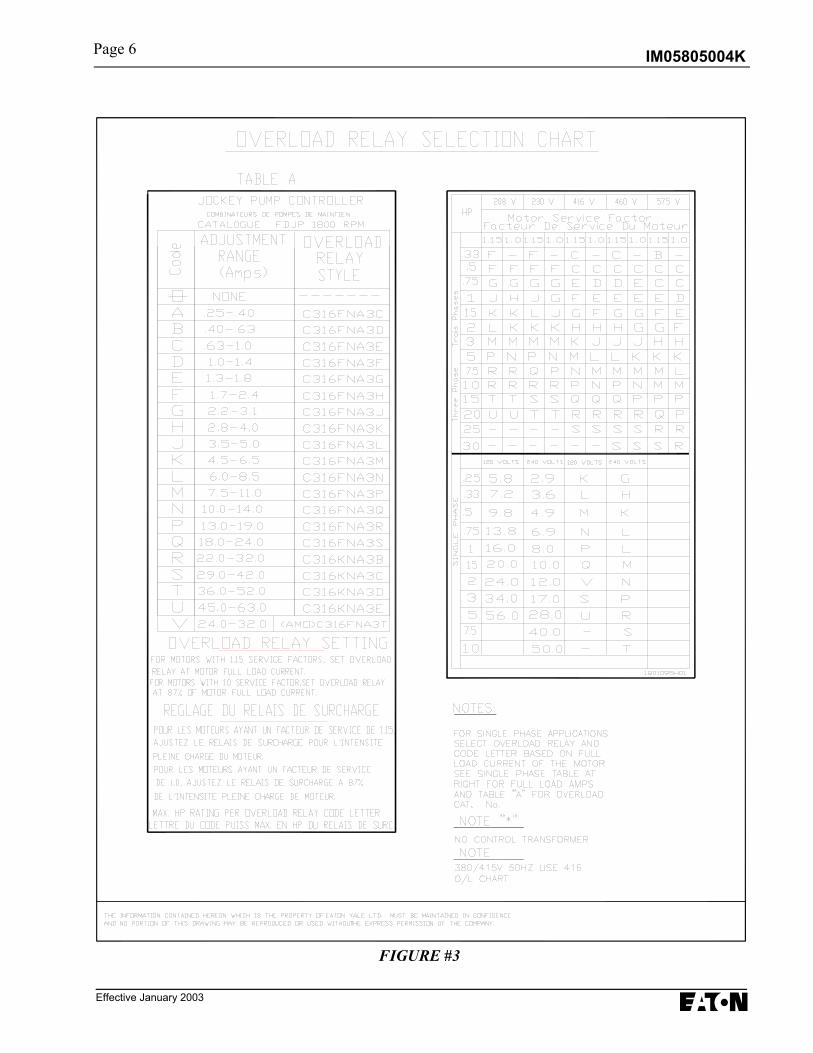
6. FIGURE 3: OVERLOAD RELAY SELECTION CHART....................................................... 6
Page i

IM05805004K Page 1
Effective January 2003
INSTALLATION & MAINTENANCEMANUAL FOR THE JOCKEY
PUMP CONTROLLER
In order to familiarize yourself with the Jockey Pump Controller, please read the instruction manual thoroughly andcarefully. Retain the manual for future reference.
1. Installation and Mounting of theController
Carefully unpack the controller and inspectthoroughly.
It is recommended that the controller is located asclose as is practical to the motor it controls
The controller is not free standing and must be boltedsecurely to a wall. For dimensional and weight dataplease refer to the respective data sheets for theJockey Pump Controller.
2. System Pressure Connection
The Jockey Pump Controller is equipped with aPressure Switch. The controller is provided with a¼” NPT female system pressure connection locatedon the bottom, external side of the enclosure. Theconnection should be installed as per NFPA,pamphlet No. 20.
NOTE: Water lines to the pressure switch must befree from dirt and contamination.
The pressure should not exceed what the pressureswitch is rated for.
3. Electrical Connections All electrical connections should meet national and local electrical codes and standards. The controller should be located or so protected thatthey will not be damaged by water escaping frompumps or pump connections. Current carrying partsof controllers shall be a minimum of 12 inches (305mm) above the floor level. • Prior to starting verify all data on the nameplate
such as, catalog number, AC line voltage andhorsepower.
• Inspect all electrical connections, componentsand wiring for any visible damage and correct asnecessary. Ensure that all electrical connectionsare tightened before energization.
• Install necessary conduit using proper methods
and tools. • Incoming AC line voltage is clearly marked L1,
L2, L3 and ground, located at the top of thebreaker.
IM05805004K
Effective January 2003
3.1 Electrical Checkout Instructions WARNING: The following procedures should be carried out by a qualified electrician familiar with the electrical
safety procedures associated with this product and its associated equipment..
3.1.1 Motor Rotation Check: With the controller energized, move the H.O.A. selector switch to "HAND" then back to“OFF” immediately to check the direction of the motor and pump rotation. If rotation direction is not correct,open the breaker and reverse the phase sequence of the load terminals of the contactor T1, T2, T3 or at the motorterminals.
3.1.2 Set up pressure switch set point as described on page 3 in these instructions. These instructions check outautomatic starting and stopping.
3.1.3 Starting and Stopping: Energize the controller. With the H.O.A. selector switch set to “AUTO”, if the systemwater pressure is lower than the pressure switch set-point pressure, the pump will start. The pump will stop whenpressure is restored. If the optional running period timer is included, the pump will run for the set time and thenreset provided pressure has been restored. For manual operation, set the H.O.A. selector switch to “HAND’ tostart the pump and “OFF” to stop.
3.1.4 Overload Relay Trip Setting: The trip setting must be set as indicated on the drawing inside the starter door or
according to the chart at the back of this manual.
3.1.5 Running Period Timer: (Optional) The RPT timer must be set for a minimum of 10 minutes. A calibrated dial isprovided on the front of the timer.
Page 3
Page 2
IM05805004K
Effective January 2003
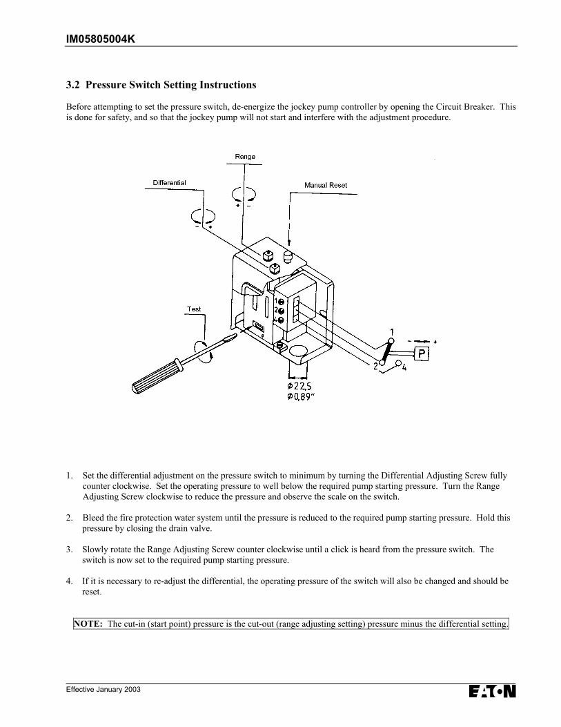
3.2 Pressure Switch Setting Instructions
Before attempting to set the pressure switch, de-energize the jockey pump controller by opening the Circuit Breaker. Thisis done for safety, and so that the jockey pump will not start and interfere with the adjustment procedure.
1. Set the differential adjustment on the pressure switch to minimum by turning the Differential Adjusting Screw fullycounter clockwise. Set the operating pressure to well below the required pump starting pressure. Turn the RangeAdjusting Screw clockwise to reduce the pressure and observe the scale on the switch.
2. Bleed the fire protection water system until the pressure is reduced to the required pump starting pressure. Hold this pressure by closing the drain valve.
3. Slowly rotate the Range Adjusting Screw counter clockwise until a click is heard from the pressure switch. The switch is now set to the required pump starting pressure.
4. If it is necessary to re-adjust the differential, the operating pressure of the switch will also be changed and should be reset.
NOTE: The cut-in (start point) pressure is the cut-out (range adjusting setting) pressure minus the differential setting.

IM05805004K
Effective January 2003
Page 4
FIGURE # 1
IM05805004K
Effective January 2003
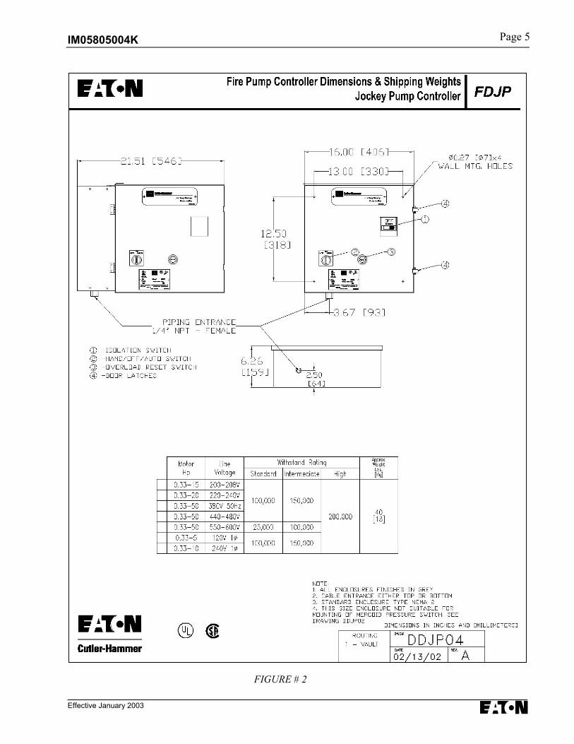
FIGURE # 2
Page 5
IM05805004K
Effective January 2003
FIGURE #3
Page 6

IM05805004K
Effective January 2003
Page 7

EATON
Cutler-Hammer403 East Lake Blvd., Airdrie, Alberta, T4A 2G1Canadatel: 403-948-7955fax: 403-948-6967www.chfire.com
© 2003 Eaton CorporationAll Rights ReservedPrinted in CanadaPublication No.: IM05805004KJanuary 2003