Embed Size (px)
Citation preview

Instructions for 10611 Fuel Rail KitThis kit is for 1997-'98 LS1 or LS6 GM enginesthat utilize a return line to the fuel tank.Note: If your fuel rail does not have two fuel lines running to it, this is the wrong kit.
Kit #10611 - Fits 1997-'98 GM LS1/LS6 utilizing a return line to the fuel tank.
NOTE: Check the drawing and bill of materials on the back side of theseinstructions to make sure you have all the parts listed. This kit is suppliedwith an adjustable fuel pressure regulator (#5). We supply fittings to connectto the stock GM inlet and return line (#13 and #12). If you are plumbing yourown lines, we recommend a -6 inlet fitting for most low to medium perform-ance street applications up to about 450 hp and the -8 for more powerfulengines. We supply optional -6AN fitting (#11) for the return and an optional-8AN inlet fitting (#6). (Use of -8 inlet will require a larger -8 hose from theregulator to the rail.) This kit is designed for the regulator to be mounted onthe firewall or inner fender panel. We supply a 16" length of -6AN hose (#18)and you can cut it to the desired length and install the reusable hose ends. Ifyou need a long length of hose, you will have to purchase it from your per-formance retailer. We recommend Professional Products Powerflow Hoseand hose ends or Aeroquip Hose and hose ends.
REMOVAL OF EXISTING FUEL RAILS (If applicable)1. Disconnect the ground connection to your vehicle's battery. This is a safe-
ty precaution. Allow engine to cool before proceeding. 2. Your stock fuel rails will have a valve on them that looks like a tire valve.This will usually be at the front end of one rail and will have a black plasticcap on it. Remove the cap. If you press on the core of the valve, it willrelease the pressure in the fuel rails. Caution!! Fuel will spray out and youshould have a towel or other absorbent cloth to catch any fuel that isreleased. Bleed system until flow stops. Wipe up any spills that may occur. 3. Remove any bolts or screws that hold the rails to the engine. New stain-less screws are provided in the kit for reattaching our rails. 4. Remove fuel inlet and return line from the rails. A special tool available atmost auto parts stores is required to remove the fuel lines. 5. Detach electrical connections from each injector. Disconnect anythingattached to fuel rails. Remove the fuel rail assembly. Each injector has an o-ring on each end of it. One end fits tightly into the rail and the other end fitstightly into the manifold. When you lift up on the rails, it may pull off of theinjectors or it may bring some of them with it. If so, be careful that they donot drop out and become damaged. Handle injectors with care. 6. Inspect the o-rings on the injectors. If you see any deterioration or cuts orslices, they must be replaced. It's not a bad idea to replace them in any eventif the vehicle is not new.
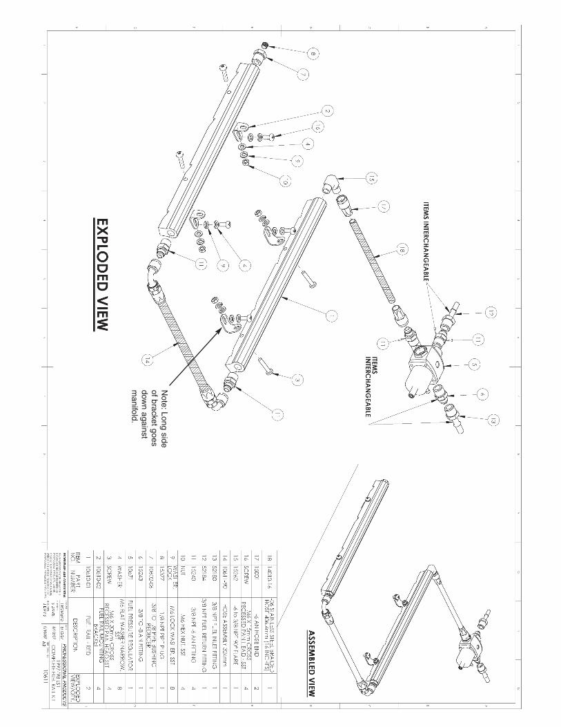
INSTALLATION OF FUEL RAIL KIT1. Lubricate O-rings on both ends of injectors with a light oil or WD-40 orequivalent. 2. Carefully push injectors into manifold. Do not cock them sideways whenyou do this or you can damage the O-ring. 3. Install all necessary fittings into fuel rails. Clamp rails in a vise with specialjaws to protect finish. Follow these instructions for installing fittings. 4. Determine which end of which rail you want to mount the fuel pressureregulator connection. This will usually be the rear of the driver's side rail.Thread the blue 90° 3/8-NPT to -6 fitting (#15) into selected rail. Do not useTeflon tape as it can shred and get into the fuel system, clogging the injec-tors. Use a special sealant for pipe threads available in any hardware store,such as Loctite #569. Please carefully follow these steps when installing anyfitting into any of the fuel rail parts. Thread fitting (with pipe sealer onthreads) into rail. Tighten it with a wrench until it stops. Then back it outabout a half a turn. Then retighten it. Each time you do this, it will go in a lit-tle further. Keep doing this until it is securely tight and in the desired posi-tion. Do not over tighten as the rail may split.5. Depending on which end of the rails you plan to use the crossover hose,thread the supplied 3/8-NPT to -6AN adapter fittings (#11) into either thefront or rear of the rails. Follow same procedure outlined in step 4. 6. Thread the 3/8-NPT to 1/8-NPT reducer (#7) into an unused port on a rail.Then thread the supplied 1/8-NPT pipe plug (#8) into the reducer. If you wantto utilize a factory style fuel pressure bleeder valve, you can get one from aFord dealer and thread it into the reducer instead of the pipe plug. The Fordpart number for the valve is E0AY-9H321-A.7. Attach stainless steel brackets (#2) to manifold with M6 x 15 S/S screws,flat washers and lockwashers. (#16, #4, #9) Snug screws down but do nottighten. Leave screws loose enough to allow brackets to be moved. NOTE:
The long leg of the bracket with the long slot in it goes down against themanifold. This is very important. If you put the bracket on backwards, therails may leak. 8. Position each fuel rail over the injectors and with lubrication on the injec-tor O-rings, carefully but firmly push rails down until you feel them seat.9. Align top end of mounting brackets (#2) with holes in rails. Move bracketsuntil holes line up. You may have to firmly push down on rails to achievealignment. Thread supplied M6 x 30 screws (#3) through rails and throughbrackets. Put flat washers, lockwashers and nuts (#4, #9, #10) onto screws.Holding rails down onto injectors with your hand, tighten screws into mani-fold and then tighten nuts on screws through rails and brackets.10. Attach crossover hose assembly (#14) to the two fittings at the end ofthe rails.11. Thread inlet and return fittings into the regulator. The return goes into thebottom of the regulator. Either of the ports on the side can be an inlet or anoutlet. Tighten fittings securely. Be sure to use sealant on the the threads. 12. Locate a mounting position for the regulator and bolt it in position usingthe supplied bracket or fabricate your own custom bracket. Attach the fuelhose assembly (#18, #17) to the regulator and to inlet fitting (#15).
FINAL STEPS OF INSTALLATION13. Go over entire system and check that every single connection is tight. 14. Reconnect battery.15. Turn on ignition so that electric fuel pump begins pumping but do notstart car. Recheck all connections for any leaks. This includes where injectorsgo into fuel rails. If leaks occur, turn off ignition. Correct any problems. Wipeup any gas puddles.16. Repeat step 15, again carefully checking for any leaks. 17. Once you are confident that no leaks occur, start engine and check forleaks again with engine running. Check where injectors seat into manifold.Again, if you see any leaks, immediately stop engine and fix the problem. 18. It is a good idea to check your system on a regular basis to make surethat no leaks develop, especially in the first few days you drive the vehicle.Gasoline leaks can turn into a very dangerous and expensive proposition.
SPECIAL INSTRUCTIONS FOR FUEL PRESSURE REGULATORSSpecial Instructions for Fuel Pressure Regulators: The regulatorsused in these fuel rail kits are factory pre-set for 40 PSI of fuel pressure. Wesuggest you check the pressure with a fuel pressure gauge. Pressureadjustments must always be made with the engine idling. Turnthe top adjustment stud clockwise for more pressure, counter-clockwise forless. Tighten lock nut once desired pressure is obtained. Typically pressureshould be set in the 40 to 50 PSI range for EFI equipped engines dependingupon the application. Check specifications for your specific system. The 3/8-NPT port on the bottom of the regulator is the bypass or return line. Either ofthe the two 3/8-NPT ports on the sides of the regulator can be used as inletor outlet. The 1/8-NPT port in the side is for a fuel pressure gauge. You canuse a Professional Products #11113 (or equivalent) which will thread directlyinto this port.
Special Note on Alternate Mounting/Plumbing Sysem: See our website atwww.professional-products.com. Go to the Fuel Rail section and look for alink called "Alternate Regulator Mounting" for a diagram showing another wayyou can plumb your fuel inlet, return, and regulator location.
If your current fuel rail doesnot look like this with twofuel line connections, thenthis is not the right kit foryour engine. If you have anLS1/LS6 with one fuel lineconnection, use our FuelRail Kit #10612.
Fuel Lines
Note:Long
sideof
bracketgoes
down
againstm
anifold.


![10611] - Senate of the Philippines 10611.pdf · r REPUBLIC ACT No. 10611] AN ACT TO STRENGTHEN THE FOOD SAFETY REGULATORY SYSTEM IN THE COUNTRY TO PROTECT CONSUMER HEALTH AND FACILITATE](https://img.dokumen.tips/doc/110x75/5ed357114e15b65b4670b50b/10611-senate-of-the-10611pdf-r-republic-act-no-10611-an-act-to-strengthen.jpg)