Embed Size (px)
Citation preview

Printed in
INSTRUCTIONS and
PARTS BOOK for
U.S. MACHINES
BASIC and SPECIAL PARTS for
All SKIP STITCH MODELS SUCH AS:
108,108-1,1 18, 118-1,
508, 508-1, 508 -C, 508 -K
518, 518-1, 518-2, 518-9,
518-A, 518-C, 518-PR , 5 18-PRB
U. S. BLIND STITCH MACHINES
U. S. BLIND STITCH MACHINE CORP.
231 West 29th Street, New York 1 , N.' • LAckawanna 4-9144 From the library of: Superior Sewing Machine & Supply LLC
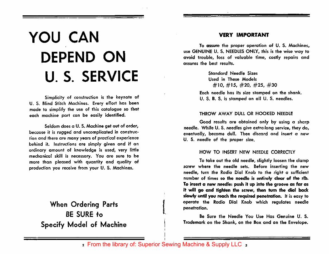
YOU CAN DEPEND ON U. S. SERVICE Simplicity of construction is the keynote of
U. S. Blind Stitch Machines. Every effort has been mode to simplify the use of this catalogue so that each machine port con be easily identified.
Seldom does aU. S. Machine get out of order, because it is rugged and uncomplicated in construction and there are many years of practical experience behind it. Instructions are simply given and if an ordinary amount of knowledge is used, very little mechanical skill is necessary. You are sure to be more than pleased with quantity and quality of production you receive from your U. S. Machines.
When Ordering Parts BE SURE to
Specify Model of Machine
2
t I
VERY IMPORTANT
To assure the proper operation of U. S. Machines,. use GENUINE U. S. NEEDLES ONLY, this is the wise way to avoid trouble, loss of valuable time, costly repairs and assures the best results.
Standard Needle Sizes Used in These Models
# 10, # 15, #20, #25, #30
Each needle has its size stamped on the shank. U. S. B. S. is stamped on all U. S. needles.
THROW AWAY DULL OR HOOKED NEEDLE
Good results are obtained only by using a sharp needle. While U. S. needles give extra long service, they do, eventually, become dull. Then discard and insert a new U. S. needle of the proper size.
HOW TO INSERT NEW NEEDLE CORRECTLY
To take out the old needle, slightly loosen the clamp screw where the needle sets. Before inserting the new needle, turn the Radio Dial Knob to the right a sufficient number of times so the needle is entirely clear of the rib. To insert a new needle: push it up into the groove as far as it will go and tighten the screw, then tum the dial back slowly until you reach the required penetration. It is easy to operate the Radio Dial Knob which regulates needle penetration.
Be Sure the Needle You Use Has Genuine U. S. Trademark on the Shank, on the Box and on the Envelope.
3 From the library of: Superior Sewing Machine & Supply LLC

THE DIAL
The dial, of course, must be adjusted to the thickness
of the fabric, so that the stitch wi ll be regular and even.
If the needle fails to catch on the right side of the material,
or bottom layer, turn the dial -a little at a time-to the left;
as the arrow points to "MORE". Run a few stitches to test.
If the needle point goes down too deep and shows too much
impression on the right side of the material, turn the dial to
the right as the arrow points to "lESS". Then test until you
have the right penetration. Only a little patience is required
for skilled adjusting.
GUIDE FOR PROPER NEEDlE PENETRATION
Dial Showing "MORE" Dial Showing "lESS"
NEW TYPE DIAl NOW USED ON U. S. MACHINES
Rib Shaft Adjustment for "MORE"
5
-.--... ·1------" --- - - -- --
Rib Shaft Adjustment for "lESS"
From the library of: Superior Sewing Machine & Supply LLC

I ,,
HOW TO THREAD Thread follows from spool or rone (A) thru 9pening and over tension (B), under bar (C) thru openings (D) and (E) then thru the needle eye (F)
THREAD BREAKAGE: HOW TO AVOID
E
See that the machine is threaded properly, as improper threading causes breakage. The thread should feed firmly, but without pull or interruption. If the stitch is loose, turn the tension nut (C) toward you. If the thread travels too. tightly, shirring the material, or if it breaks, turn the tension nut (C) away from you which will loosen tension of the spring.
After substantial service, the needle will be inclined to cut a sharp edge in the groove of the needle guide, causing thread breakage. When this occurs, we suggest replacing needle guide: part #47.
Sometimes a groove will be caused in the opening of needle clamp (E) by constant thread friction; this also will cause thread breakage. You can avoid this by changing needle clamp: part #36.
6
.;.
OIL IS THE LIFE OF THE MACHINE
Be SURE to oil every movable part wherever oil cups
or open holes are located EVERY DAY, especially when the
machine is new. When oiling, insert the oil spout firmly.
Use proper lubricating oil.
By observing these simple instructions, you will
secure satisfactory results from your machine. If you do run
into any trouble, get in touch with our main office, or the
representative from whom you bought the machine.
HAND WHEEL
The hand wheel must always turn away from the
operator.
SPEED
Speed of the machine depends on the model. On
all skip (or interval) stitch machines, we recommend speed
from 2,000 to 3,000 stitches per minute.
Very Important: Do not mount machine on high
speed motors.
7 From the library of: Superior Sewing Machine & Supply LLC
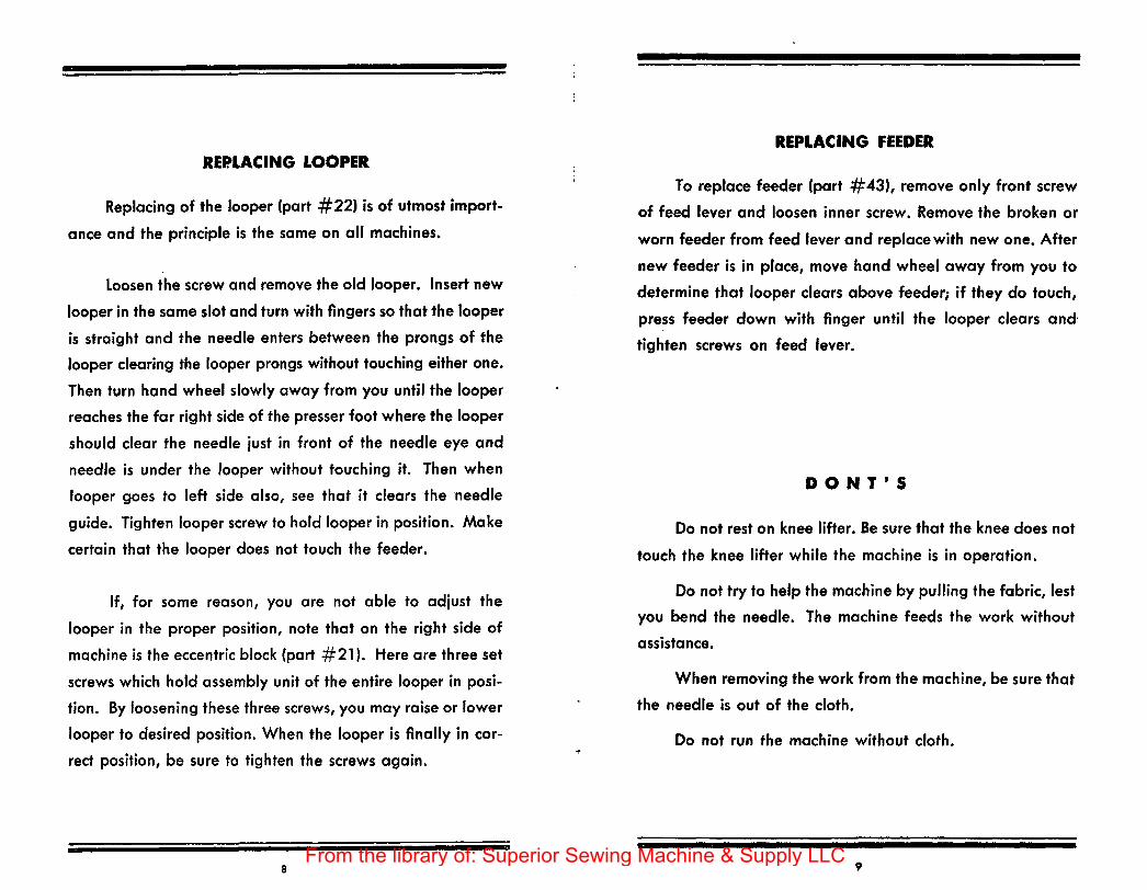
REPLACING LOOPER
Replacing of the looper (part #22) is of utmost importM
once and the princi-ple is the same on all machines.
Loosen the screw and remove the old looper. Insert new
looper in the same slot and turn with fingers so that the looper
is straight and the needle enters between the prongs of the
looper clearing the looper prongs without touching either one.
Then turn hand wheel slowly away from you until the looper
reaches the far right side of the presser foot where the looper
should clear the needle iust in front of the needle eye and
needle is under the looper without touching it. Then when
looper goes to left side also, see that it clears the needle
guide. Tighten looper screw to hold looper in position. Make
certain that the looper does not touch the feeder.
If, for some reason, you are not able to adiust the
looper in the proper position, note that on the right side of
machine is the eccentric block (part #21 ). Here are three set
screws which hold assembly unit of the entire looper in posiM
tion. By loosening these three screws, you may raise or lower
looper to desired position. When the looper is finally in cor
rect position, be sure to tighten the screws again.
8
,.
REPLACING FEEDER
To replace feeder (part #43), remove only front screw
of feed lever and loosen inner screw. Remove the broken or
worn feeder from feed lever and replace with new one. After
new feeder is in place, move hand wheel away from you to
determine that looper clears above feeder; if they do touch,
press feeder down with finger until the looper clears and·
tighten screws on feed lever.
DO NT'S
Do not rest on knee lifter. Be sure that the knee does not
touch the knee lifter while the machine is in operation.
Do not try to help the machine by pulling the fabric, lest
you bend the needle. The machine feeds the work without
assistance.
When removing the work from the machine, be sure that
the needle is out of the cloth.
Do not run the machine without cloth.
9 From the library of: Superior Sewing Machine & Supply LLC

23B
NUMBER NAME ' 6 Feed Eccentric 110
6 -B Stitch Regulating Collar I
7 Needle Connection 85
9 -B Rib Lever Eccentric.
1 0-B Rib Connection Lever I 23-B Main Shaft 97
32 Eccentric Ball Stud
33 Eccentric Ball Guard I 32
85 Rib Lever Eccentric Screw 99
97 Feed Eccentric Screw
99 Needle Connection Screw T 100-B Rib Lever Clamp Screw IOOB
110 Eccentric Ball Guard Screw
98 33
WHEN ORDERING PARTS SPECIFY MODEL
10 ,, From the library of: Superior Sewing Machine & Supply LLC

NUMBER NAME
8-B Feed Lever
30 Needle Shaft
34 Needle Shaft Clamp Collar
T 35 Needle Lever 87
36 Needle Clamp
38-B Feed lever Rocker Pin 388 43 43 Feeder 0 87 Feeder Screw 0
.
116L 90 Needle lever Clamp Screw
100 Needle Clamp Screw 34
100 Needle Shaft Crank Screw E' cy -- t !!!!!!'~! ~ ~E : 116-l Feed lever Rocker Pin Collar
: I
30
I ' 100
35 90 36
12 13 From the library of: Superior Sewing Machine & Supply LLC

NUMBER NAME
44 44-C
45 46 47 48 48 49-A
49-C
50-A 51-A 52 86 87 92 93 1 11 125 126 126-A
125-A 125-B 125-C 125-D 125-E 125-F
Presserfoot for Models 108, 118, 508 & 518 Presserfoot for Models 1 08-1, 118-1 , 508-1, 508-C, 508- K, 518-1, 518-2, 518-9, 518-A ,518-C
P resserfoo·~ Brace Presserfoot Eccentric Pin Needle Guide Needle Gu ide Screw Front Guide Holder Screw Presserfoot Shoe for Models 108 and 118
508 and 518
Presserfoot Shoe for Models 108-1 and 118-1 508-1, 508-C, 508-K 518-1, 518-2 , 518-9 518- A I 518-C
Presserfoot Shoe Spring Presserfoot Shoe Pin Presserfoot Shoe Stud Presserfoot Clamp Screw Presserfoot Brace Screw Front Guide Holder Clamp Screw Front Guide Holder Nut Shoe Pin Ho lder Screw Front Guide Front Guide Holder Front Guide Holder
For Models 518-A and 518-2 ONLY
Not For Factory Use Store Alte ration Departments ONLY
Front Guide Front Guide Block Front Guide Ad justing Knob Front Guide Block Clamp Screw Front Guide Clamp Screw Front Guide Block Check Screw
Be Sure to Specify Model of your Machine
14
,,. 52 87 86
440R44-C Pll SOA SIA
92 125 93 126
• 125-B 125-C
' ' ' 125-A IZS-D 125-E 125-F
II Ill
Ill
46
rat 47
,, 49-C
126 A
FOR MODELS 518-A
AND 518-2
ONLY
WHEN ORDERING PARTS SPECIFY MODEL
15 From the library of: Superior Sewing Machine & Supply LLC
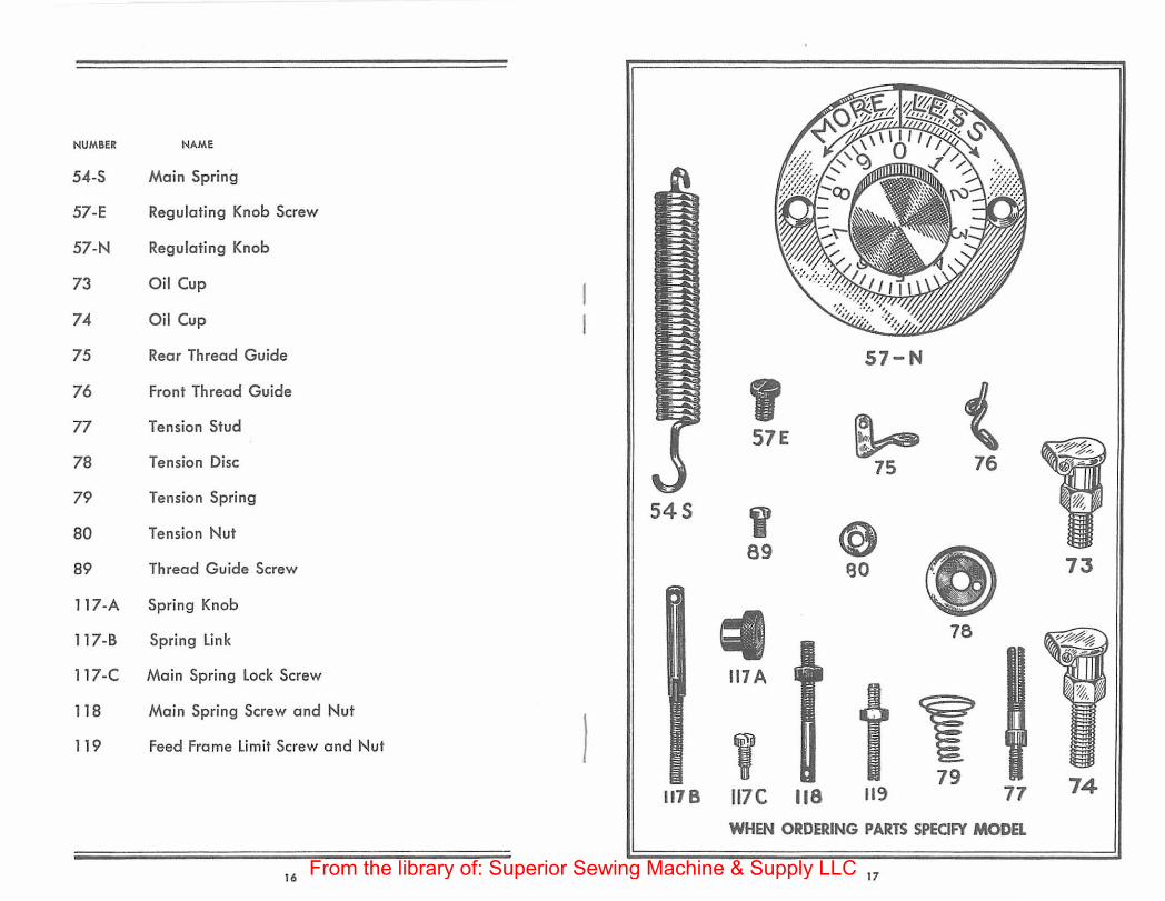
NUMBER
54-S
57-E
57-N
73
74
75
76
77
78
79
80
89
NAME
Main Spring
Regulating Knob Screw
Regulating Knob
Oil Cup
Oil Cup
Rear Thread Guide
Front Thread Guide
Tension Stud
Tension Disc
Tension Spring
Tension Nut
Thread Guide Screw
117 -A Spring Knob
117-B Spring Link
117-C Main Spring Lock Screw
118
119
Main Spring Screw and Nut
Feed Frame Limit Screw and Nut
16
545
l 1178
57-N
' 57E ~ 75
( 76
I 89 @
eo 73
78
11 7A
' 117C 118
y 79
119 74 77
WHEN ORDERING PARTS SPECIFY MODEL
17 From the library of: Superior Sewing Machine & Supply LLC

NUMBER
12
13
14
15
16
17
18
19
20
NAME
Looper Rod Sleeve
looper Rod Sleeve Stud
looper Rod Sleeve Clamp Collar
Looper Rod Fork
Looper Rod Fork Pin
Looper Rod
looper Rod Ball
Looper Rod Carrier
Looper Rod Carrier Stud
21 Eccentric Block
22 looper
83 Eccentric Block Clamp
84 Eccentric Block Clamp Screw
91
94
95
98
99
100
101
105
Looper Fork Clamp Srew
looper Sleeve Pin Screw
Looper Rod Ball Screw
Eccentric Block Screw
Looper Rod Carrier Clamp Screw
Sleeve Collar Clamp Screw
Looper Clamp Screw
looper Rod Nut
12
II 94
17
~ 105
13
0 18
19
I 99
14
(J 95
IS
I 100
20
D 83
lJ 101
I 91
ll
I 64
I 98
WHEN ORDERING PARTS SPECIFY MODEL
19
16
From the library of: Superior Sewing Machine & Supply LLC

NUMBER NAME
11 -l Left Platten Bracket
11-R Right Platten Bracket
61 -C Rib Shaft V Shape for Models 108, 108-1, 118, 118-1 , 508, 508-1,508-C,508-K , 518, 518-1, 518-2, 518-91 518-A, 518-C
63 Rib Shaft Crank
64 Rib Shaft Crank Stud
65 Rib Shaft Crank Clamp Stud
66 Bracket Stud
67-L
67-R
68
69
100
103
104
108
116
116-A
Left Platten
Right Platten
Platten Screw
Platten Spring
Rib Shaft Collar Clamp Screw
Bracket Limit Screw
Bracket Limit Screw Nut
Platten Screw Nut
Left Rib Shaft Collar
Right Rib Shaft Col lar
20
61C
I 64
66 11-L 11- R
I ~ 104
103
' 68 69
§ 108
67- L 67-R
~ 116 ' 100
§ 116A
v 65
rD 63
21 From the library of: Superior Sewing Machine & Supply LLC

NUMBER NAME
150-A Swing Plate
151-A Swing Plate Bracket 151-A
165 Swing Plate Pivot Stud and Nut Complete
166 Swing Plate lock Screw and Wing Nut
167 Cylinder
168 Cylinder Screw
ISO-A
167
I 168
165 166
WHEN ORDERING PARTS SPECIFY MODEL
22 23 From the library of: Superior Sewing Machine & Supply LLC

NUMBER NAME
142 Supporting Bracket lock Washer
143 Supporting Bracket Washer
144 Supporting Bracket Screw
146 Knee lifter Bracket Screw
147 Knee lifter Bracket lock Washer
150-C Front Plate for Model 518-9 ONlY
151 -C Front Plate Bracket for Model 518-9 ONlY
153 Knee Lifter Bracket
152 Knee lifter Rod
153 -,., I 146
154 Knee Pedal
155-A Knee Lifter Stop Bracket
~ 0 147
160
156 lifting Bracket
160 Knee lifter Stop Bracket Hook
161 Knee lifter Supporting Spring 155-A
0 154 14Z 14l 144
156
152
WHEN ORDERING PARTS SPECIFY MODEL
24 25 From the library of: Superior Sewing Machine & Supply LLC

NUMBER NAME
3-B Feed Frame for 108, 108-1, 118, 118-1 Not Illustrated
I 3-N Feed Frame for 508, 508-1,508-C, 508-K 518, 518-1,518-2, 518-9,518-A, 518-C 518-PR 518-PRB 172
4-A New Style Cover
24 Hand Wheel
24-V Hand Wheel V Belt Drive (Not illustrated)
53-B Feed Frame Shaft
72 Belt Guard
85 Belt Guard Screw 4-A
' ' 94 lever Stud Clamp Screw 100 97
94 Feed Frame Shaft Clamp Screw 53B I
97 Hand Wheel Screw 98
98 Hand Wheel Screw
100 Cover Screw 85
109 Belt Guard Wcsher
' 2.4 @
169 Skip Regulator lever
i 109
170 lever Stud and Washer 170 I
171 lever Nut and Screw 171 94
172 left & Right Feed Frame Bushing 169
WHEN ORDERING PARTS SPECIFY MODEL
' "' ?7
From the library of: Superior Sewing Machine & Supply LLC

SKIP STJTCH GEAR ASSEMBLY
It is very important to specify the Model Number when
ordering these parts, because on all 508 and 108 models,
the skip stitch assembly is three to one (3 to 1) ratio and on
all 518 and 118 models the skip stitch assembly is two to
one (2 to 1) ratio, therefore the model number of your
machine is imperative.
NUMBER NAME
1-S Skip Stitch Gears Complete
2-S Small Gear
9-S Eccentric
28-S Clamping Collar
(./1 I
<X)
""
V) I
0\
a (/') • N
·~ ~
LIJ ..... 2 w ..J Q.
(")
"'
~ 0 u
~ Qj
-o 0 ~ co 0
V) I -o - c:
0
co 0 I.()
c: 0
-o c: 0
0
0 ...
2 N
"' <II -Qj ·c
-o ::;)
0 <II
:E -= co Ol c:
-o a:; c: -o 0 ...
co 0
c: I.() Qj
..c: 0 ~
c: Qj 0 -o - 0 c: ::;)
:E Qj ·>-..._ ~ ·;:;
Qj 0.. 0.. E "' 0 Qj u
"' .~ 0 ..c: ~ f- a..
29 From the library of: Superior Sewing Machine & Supply LLC

SPECIAL PARTS FOR
MODEL 51 S-PR AND 518-PRB ONLY
NUMBER NAME
11 -PR Platten Bracket
31-F
43-F
Hemmer Bracket Complete
Feeder
44-F Presserfoot
49-PR Shoe
61-F Rib Shaft
67 -F Platten
68-PR Platten Stud
1 00 Hemmer· Bracket Screw
1 03-PR Platten Bracket Limit Screw
1 04-PR Platten Bracket Limit Screw Nut
108 Platten Stud Nut
11 0-PR Bridge Bracket Screw
11 0-PR Shoe Screw
173 Hemmer (Specify s;ze and whether A or 8)
17 4 Hemmer Side Bracket
30
l
49-PR
43-F
44-F
11-PR
31-F
67-F
@
174 108
173
' ' ' 110-PR 100
WHEN ORDERING PARTS SPECIFY MODEL
31
I IIO·PR
61-F
From the library of: Superior Sewing Machine & Supply LLC