Embed Size (px)
Citation preview
Instruction Set Architecture: Chapter 9
Concepts• Computer Software Instructions:
– Machine language = binary language in which instructions are defined and stored– Assembly language = replaces binary opcodes and addresses with symbolic names
• Computer Architecture (the old definition): a computer is comprised of– Architecture
• instruction set/software
– Implementation of the architecture• Organization – i.e. datapaths, control units, memories, and buses• Hardware – i.e. logic, electronic technology, physical design attributes
• Computer Architecture (today’s definition): a computer is comprised of– Instruction Set Architecture– Organization– Hardware
• The word architecture applies to the integration of all three.
• Merit of the new definition is the following:• more integrated viewpoint• aids in obtaining a tightly coupled design process• allows intelligent design trade-offs
R. W. Knepper, SC312page 9-1
More on Computer Architecture Concepts• Typical instruction format:
– opcode field - specifies the operation to be performed
– address field - provides either a memory address or processor register address
– mode field - specifies interpretation of address field
• Register set: all the registers in the CPU that are accessible to the programmer– register file (accessible portion)
– program counter PC
– processor status register PSR• status bits C, N, V, & Z (from ALU) referred to as condition codes or flags
• used to make decisions that determine program flow (branch or jump)
– stack pointer SP
• Basic computer operation cycle (PC holds the address of the next instruction)– 1. fetch the instruction from memory into a control register
– 2. decode the instruction
– 3. locate the operands
– 4. fetch the operands from memory (if necessary)
– 5. execute the operation in processor registers
– 6. store the results
– 7. start over again with fetch the next instruction
R. W. Knepper, SC312page 9-2
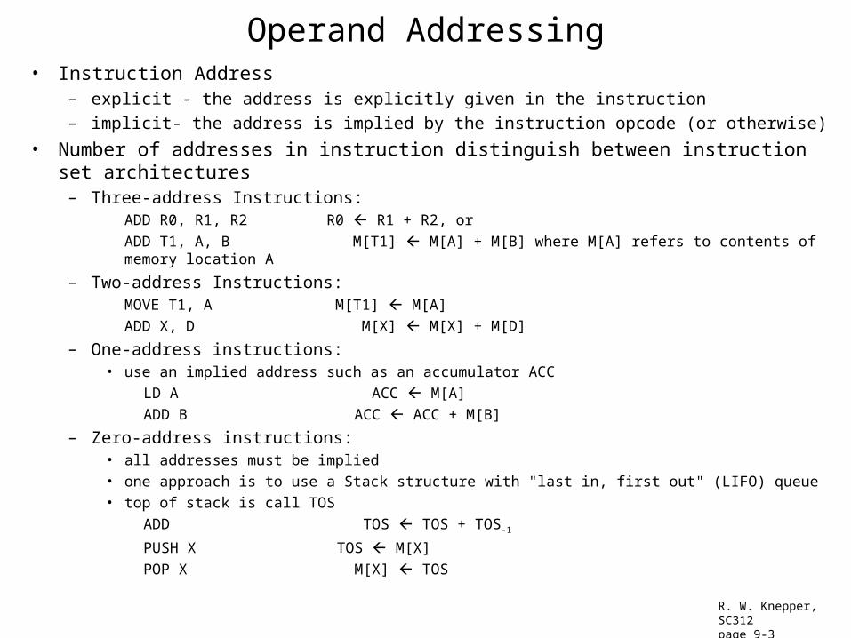
Operand Addressing• Instruction Address
– explicit - the address is explicitly given in the instruction
– implicit- the address is implied by the instruction opcode (or otherwise)
• Number of addresses in instruction distinguish between instruction set architectures– Three-address Instructions:
ADD R0, R1, R2 R0 R1 + R2, or
ADD T1, A, B M[T1] M[A] + M[B] where M[A] refers to contents of memory location A
– Two-address Instructions:MOVE T1, A M[T1] M[A]
ADD X, D M[X] M[X] + M[D]
– One-address instructions:• use an implied address such as an accumulator ACC
LD A ACC M[A]
ADD B ACC ACC + M[B]
– Zero-address instructions:• all addresses must be implied
• one approach is to use a Stack structure with "last in, first out" (LIFO) queue
• top of stack is call TOS
ADD TOS TOS + TOS-1
PUSH X TOS M[X]
POP X M[X] TOS R. W. Knepper, SC312page 9-3
Addressing Architectures• memory-to-memory architecture
– three address architecture with all accesses to memory– low instruction count, but high execution time– not used in new designs today
• register-to-register (or load/store) architecture– three address architecture using only load and store for memory accesses– requires large register file– higher number of instructions, but faster execution time– typical of today's processors
• register-memory architecture– variation of above two approaches often used for two-address instructions
ADD R1, A R1 R1 + M[A]
– still prevalent today
• single-accumulator architecture– single-address instructions; no register file– low-cost, low-performance applications
• stack architecture– used for zero-address instruction case– reverse Polish notation (RPN) was popular for early hand-held calculators
• named for Polish mathematician Jan Lukasiewicz
R. W. Knepper, SC312page 9-4
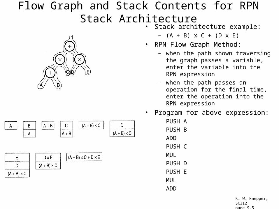
Flow Graph and Stack Contents for RPN Stack Architecture• Stack architecture example:
– (A + B) x C + (D x E)
• RPN Flow Graph Method: – when the path shown traversing the graph
passes a variable, enter the variable into the RPN expression
– when the path passes an operation for the final time, enter the operation into the RPN expression
• Program for above expression:PUSH A
PUSH B
ADD
PUSH C
MUL
PUSH D
PUSH E
MUL
ADD
R. W. Knepper, SC312page 9-5
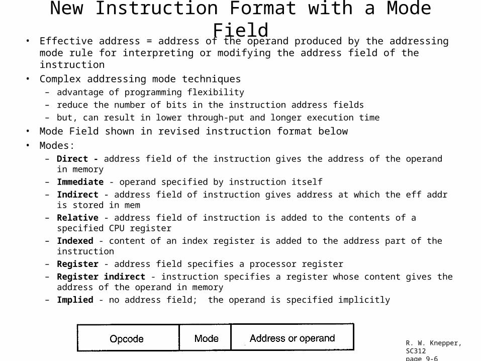
New Instruction Format with a Mode Field• Effective address = address of the operand produced by the addressing mode rule for
interpreting or modifying the address field of the instruction
• Complex addressing mode techniques – advantage of programming flexibility
– reduce the number of bits in the instruction address fields
– but, can result in lower through-put and longer execution time
• Mode Field shown in revised instruction format below
• Modes:– Direct - address field of the instruction gives the address of the operand in memory
– Immediate - operand specified by instruction itself
– Indirect - address field of instruction gives address at which the eff addr is stored in mem
– Relative - address field of instruction is added to the contents of a specified CPU register
– Indexed - content of an index register is added to the address part of the instruction
– Register - address field specifies a processor register
– Register indirect - instruction specifies a register whose content gives the address of the operand in memory
– Implied - no address field; the operand is specified implicitly
R. W. Knepper, SC312page 9-6
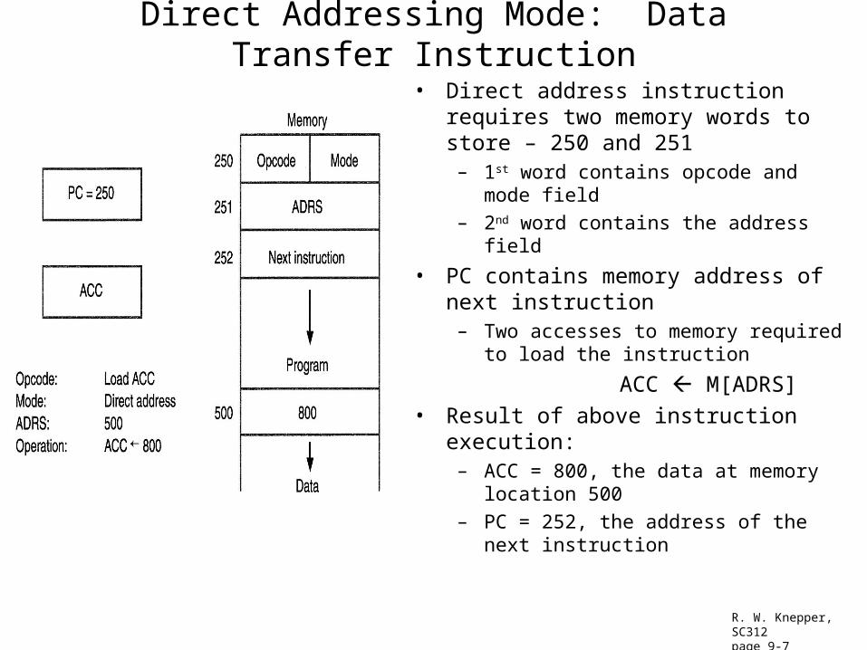
Direct Addressing Mode: Data Transfer Instruction
• Direct address instruction requires two memory words to store – 250 and 251
– 1st word contains opcode and mode field
– 2nd word contains the address field
• PC contains memory address of next instruction
– Two accesses to memory required to load the instruction
ACC M[ADRS]
• Result of above instruction execution:– ACC = 800, the data at memory location 500
– PC = 252, the address of the next instruction
R. W. Knepper, SC312page 9-7
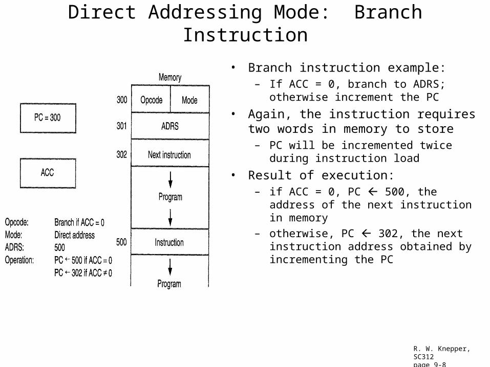
Direct Addressing Mode: Branch Instruction
• Branch instruction example:– If ACC = 0, branch to ADRS; otherwise
increment the PC
• Again, the instruction requires two words in memory to store
– PC will be incremented twice during instruction load
• Result of execution:– if ACC = 0, PC 500, the address of the next
instruction in memory
– otherwise, PC 302, the next instruction address obtained by incrementing the PC
R. W. Knepper, SC312page 9-8
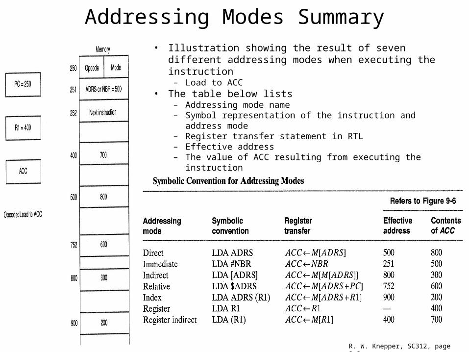
Addressing Modes Summary• Illustration showing the result of seven different addressing
modes when executing the instruction– Load to ACC
• The table below lists– Addressing mode name– Symbol representation of the instruction and address mode– Register transfer statement in RTL– Effective address– The value of ACC resulting from executing the instruction
R. W. Knepper, SC312, page 9-9
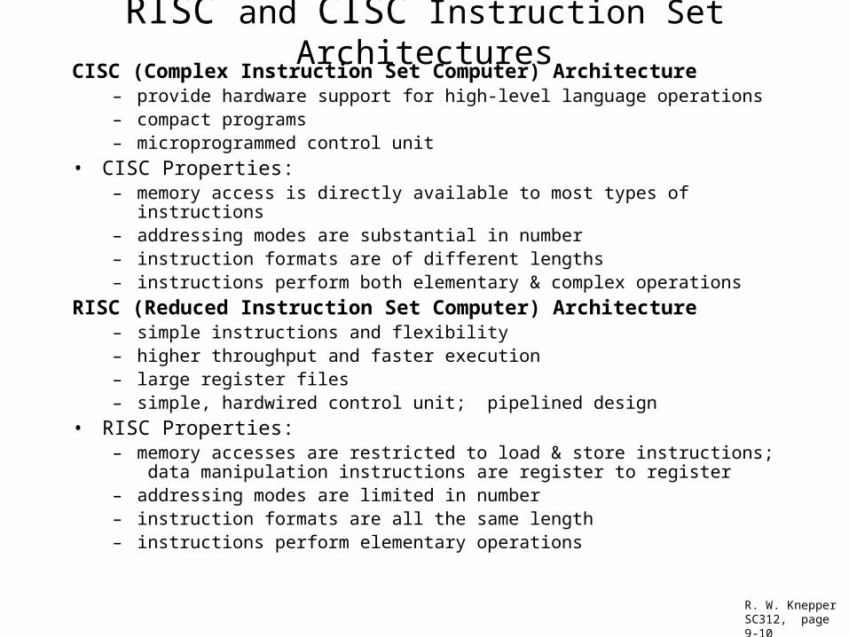
RISC and CISC Instruction Set ArchitecturesCISC (Complex Instruction Set Computer) Architecture
– provide hardware support for high-level language operations– compact programs– microprogrammed control unit
• CISC Properties:– memory access is directly available to most types of instructions– addressing modes are substantial in number– instruction formats are of different lengths– instructions perform both elementary & complex operations
RISC (Reduced Instruction Set Computer) Architecture– simple instructions and flexibility– higher throughput and faster execution– large register files– simple, hardwired control unit; pipelined design
• RISC Properties:– memory accesses are restricted to load & store instructions; data manipulation
instructions are register to register– addressing modes are limited in number– instruction formats are all the same length– instructions perform elementary operations
R. W. KnepperSC312, page 9-10
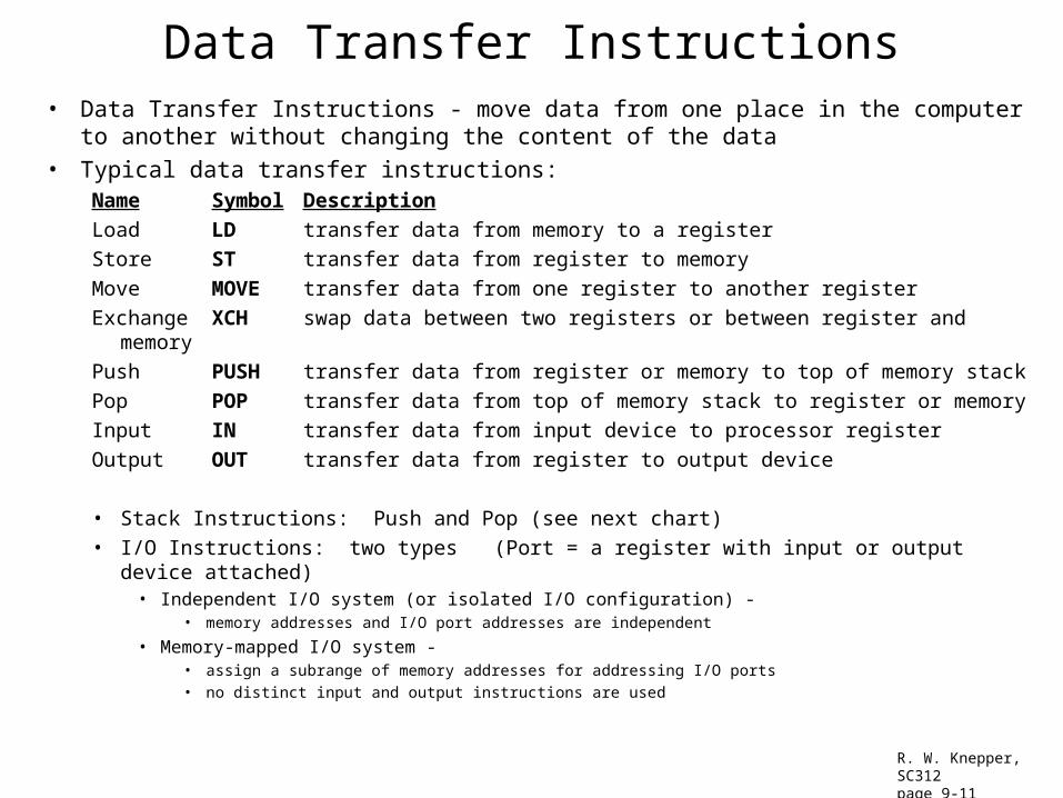
Data Transfer Instructions• Data Transfer Instructions - move data from one place in the computer to another
without changing the content of the data• Typical data transfer instructions:
Name Symbol Description
Load LD transfer data from memory to a register
Store ST transfer data from register to memory
Move MOVE transfer data from one register to another register
Exchange XCH swap data between two registers or between register and memory
Push PUSH transfer data from register or memory to top of memory stack
Pop POP transfer data from top of memory stack to register or memory
Input IN transfer data from input device to processor register
Output OUT transfer data from register to output device
• Stack Instructions: Push and Pop (see next chart)
• I/O Instructions: two types (Port = a register with input or output device attached)• Independent I/O system (or isolated I/O configuration) -
• memory addresses and I/O port addresses are independent
• Memory-mapped I/O system - • assign a subrange of memory addresses for addressing I/O ports• no distinct input and output instructions are used
R. W. Knepper, SC312page 9-11
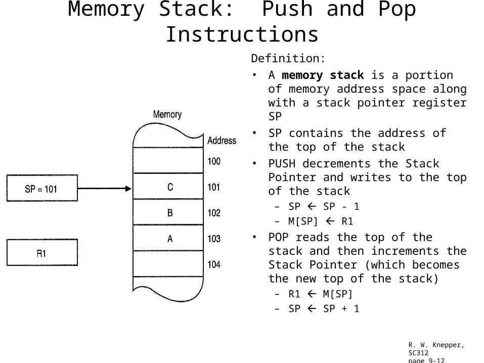
Memory Stack: Push and Pop Instructions
Definition:
• A memory stack is a portion of memory address space along with a stack pointer register SP
• SP contains the address of the top of the stack
• PUSH decrements the Stack Pointer and writes to the top of the stack
– SP SP - 1
– M[SP] R1
• POP reads the top of the stack and then increments the Stack Pointer (which becomes the new top of the stack)
– R1 M[SP]
– SP SP + 1
R. W. Knepper, SC312page 9-12
Data Manipulation Instructions• Data Manipulation Instructions - perform operations on data
– providing the computational capabilities of the computer
– usually involves a sequence of several microoperations (such as instruction fetch, instruction decode and operand fetch, execution, & write-back)
• Three types of data manipulation instructions:– Arithmetic instructions
– Logical and bit manipulation instructions
– Shift instructions
R. W. Knepper, SC312page 9-13
Typical Arithmetic Instructions
• add, subtract, multiply, divide (ADD, SUB, MUL, DIV)– can work with signed or unsigned integers, binary or decimal number, or floating-point
data
• increment, decrement (INC, DEC)– add/subtract 1 to/from a number
• add with carry (ADDC)– adds two operands plus the previous carry
• subtract with borrow (SUBB)– subtracts two operands and a borrow from previous operation
• subtract reverse (SUBR)– reverses the order of the operands prior to subtracting
• negate (NEG)– performs 2's complement of a signed number
Note: The results of arithmetic operations are of finite precision!!! Computers can use double precision (64 bit) or single precision (32 bit) depending on the precision desired.
R. W. Knepper, SC312page 9-14
Typical Logic and Bit Manipulation Instructions
Note: Consider each bit separately and treat as a Boolean variable.
• Clear (CLR)– causes the operand bits to be set to all zeros
• Set (SET)– causes the operand to be set to all ones
• Complement (NOT)– inverts all the bits of the operand
• AND - Boolean AND function– can selectively clear bits to "0" using a mask with zeros
– called "bit clear" instruction
• OR - Boolean OR function– can selectively set bits to "1" using a mask with ones
– called "bit set" instruction
• Exclusive OR - Boolean XOR function– can selectively complement a string of bits with a mask with ones
– called "bit complement"
• Clear carry CLRC, Set carry SETC, Complement carry COMC - operate on the carry bit
R. W. Knepper, SC312page 9-15
Typical Shift InstructionsFive fields: OP REG TYPE RL COUNT
OP is the opcode
REG is the register address of the operand
TYPE is a 2-bit field giving one of the four types of shifts
RL is a single bit telling if the shift is to the right or left
COUNT is a k-bit field specifying shifts of up to 2k – 1 bit positions
• Logical shift right (left) SHR, SHL– inserts a "0" in the left-most or right-most position after shift
• Arithmetic shift right (left) SHRA, SHLA– preserves the sign bit in the left-most position on right shift
– may set the overflow V bit on a left shift
• Rotate right (left) ROR, ROL– produces a circular shift
• Rotate right (left) with carry RORC, ROLC– includes carry bit in circular shift
R. W. Knepper, SC312page 9-16
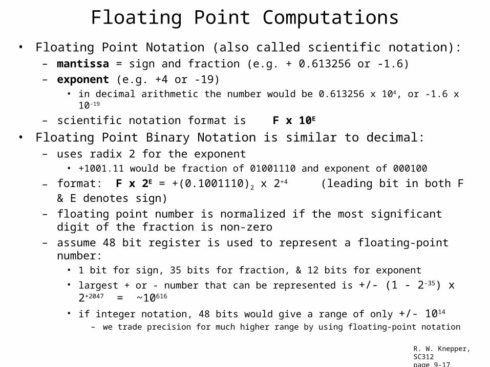
Floating Point Computations
• Floating Point Notation (also called scientific notation):– mantissa = sign and fraction (e.g. + 0.613256 or -1.6)
– exponent (e.g. +4 or -19)• in decimal arithmetic the number would be 0.613256 x 10⁴, or -1.6 x 10⁻¹⁹
– scientific notation format is F x 10E
• Floating Point Binary Notation is similar to decimal:– uses radix 2 for the exponent
• +1001.11 would be fraction of 01001110 and exponent of 000100
– format: F x 2E = +(0.1001110)2 x 2+4 (leading bit in both F & E denotes sign)
– floating point number is normalized if the most significant digit of the fraction is non-zero
– assume 48 bit register is used to represent a floating-point number:• 1 bit for sign, 35 bits for fraction, & 12 bits for exponent
• largest + or - number that can be represented is +/- (1 - 2-35) x 2+2047 = ~10616
• if integer notation, 48 bits would give a range of only +/- 1014
– we trade precision for much higher range by using floating-point notation
R. W. Knepper, SC312page 9-17
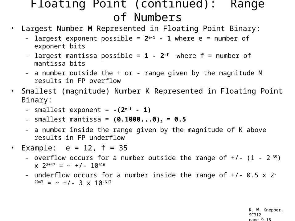
Floating Point (continued): Range of Numbers
• Largest Number M Represented in Floating Point Binary: – largest exponent possible = 2e-1 - 1 where e = number of exponent bits
– largest mantissa possible = 1 - 2-f where f = number of mantissa bits
– a number outside the + or - range given by the magnitude M results in FP overflow
• Smallest (magnitude) Number K Represented in Floating Point Binary:– smallest exponent = -(2e-1 - 1)
– smallest mantissa = (0.1000...0)2 = 0.5
– a number inside the range given by the magnitude of K above results in FP underflow
• Example: e = 12, f = 35– overflow occurs for a number outside the range of +/- (1 - 2-35) x 22047 = ~ +/- 10616
– underflow occurs for a number inside the range of +/- 0.5 x 2-2047 = ~ +/- 3 x 10-617
R. W. Knepper, SC312page 9-18

Arithmetic Operations in Floating Point• addition or subtraction require aligning the radix point
– shift the fraction with the smaller exponent to the right to align the exponents
– add the fractions (leave exponent unchanged)
– normalize if necessary to correct bit overflow or non-normalized result
• multiplication and division do not require alignment– multiply the fractions
– add the exponents
– sign given by XOR of signs of starting numbers
– normalize as necessary
• Biased exponent representation is employed in most computers– a bias (excess number) is added to the exponent so that all internal exponents are positive
• the most negative exp (smallest positive number) converts to a biased exp with all 0's
• floating point representation of zero is a zero fraction and a zero biased exponent
– add 2e-1 - 1 to the exponent during representation; subtract 2e-1 -1 during manipulation
– Example with e = 4 and f = 4: add 24-1 – 1 = 7 to the exponent (smallest exp becomes 0000)
• Standard Operand Format:– Suffix F is used for floating point instructions (e.g. ADDF)
• 32 bit single-precision uses FS
• 64 bit double-precision uses FL (for floating-point long)
R. W. Knepper, SC312page 9-19
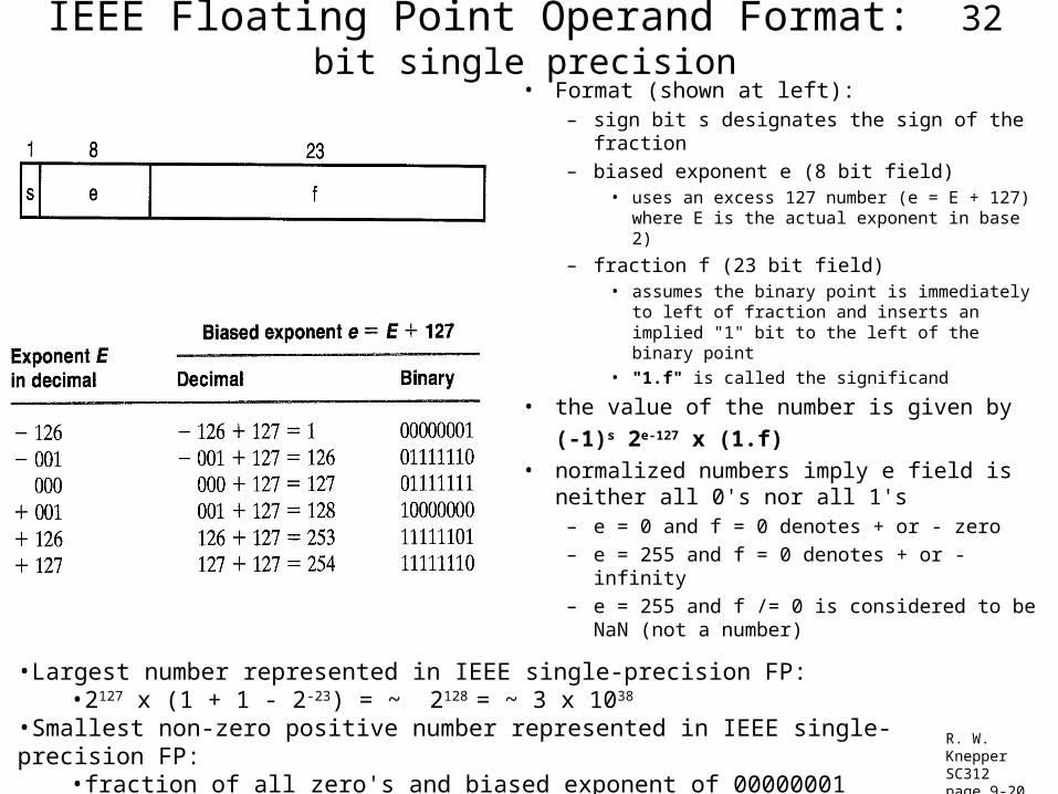
IEEE Floating Point Operand Format: 32 bit single precision
• Format (shown at left):– sign bit s designates the sign of the fraction
– biased exponent e (8 bit field) • uses an excess 127 number (e = E + 127)
where E is the actual exponent in base 2)
– fraction f (23 bit field) • assumes the binary point is immediately to
left of fraction and inserts an implied "1" bit to the left of the binary point
• "1.f" is called the significand
• the value of the number is given by
(-1)s 2e-127 x (1.f)
• normalized numbers imply e field is neither all 0's nor all 1's
– e = 0 and f = 0 denotes + or - zero
– e = 255 and f = 0 denotes + or - infinity
– e = 255 and f /= 0 is considered to be NaN (not a number)
R. W. KnepperSC312page 9-20
•Largest number represented in IEEE single-precision FP:•2127 x (1 + 1 - 2-23) = ~ 2128 = ~ 3 x 1038
•Smallest non-zero positive number represented in IEEE single-precision FP:•fraction of all zero's and biased exponent of 00000001 yields 2 (1 - 127) = 2-126 = ~ 10-38
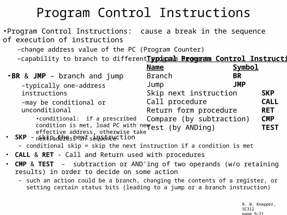
Program Control Instructions
• SKP - skip the next instruction– conditional skip = skip the next instruction if a condition is met
• CALL & RET - Call and Return used with procedures
• CMP & TEST - subtraction or AND'ing of two operands (w/o retaining results) in order to decide on some action
– such an action could be a branch, changing the contents of a register, or setting certain status bits (leading to a jump or a branch instruction)
R. W. Knepper, SC312page 9-21
Typical Program Control InstructionsName SymbolBranch BRJump JMPSkip next instruction SKPCall procedure CALLReturn form procedure RETCompare (by subtraction) CMPTest (by ANDing) TEST
•Program Control Instructions: cause a break in the sequence of execution of instructions–change address value of the PC (Program Counter)
–capability to branch to different program segments
•BR & JMP – branch and jump–typically one-address instructions
–may be conditional or unconditional•conditional: if a prescribed condition is met, load PC with new effective address, otherwise take next address in sequence
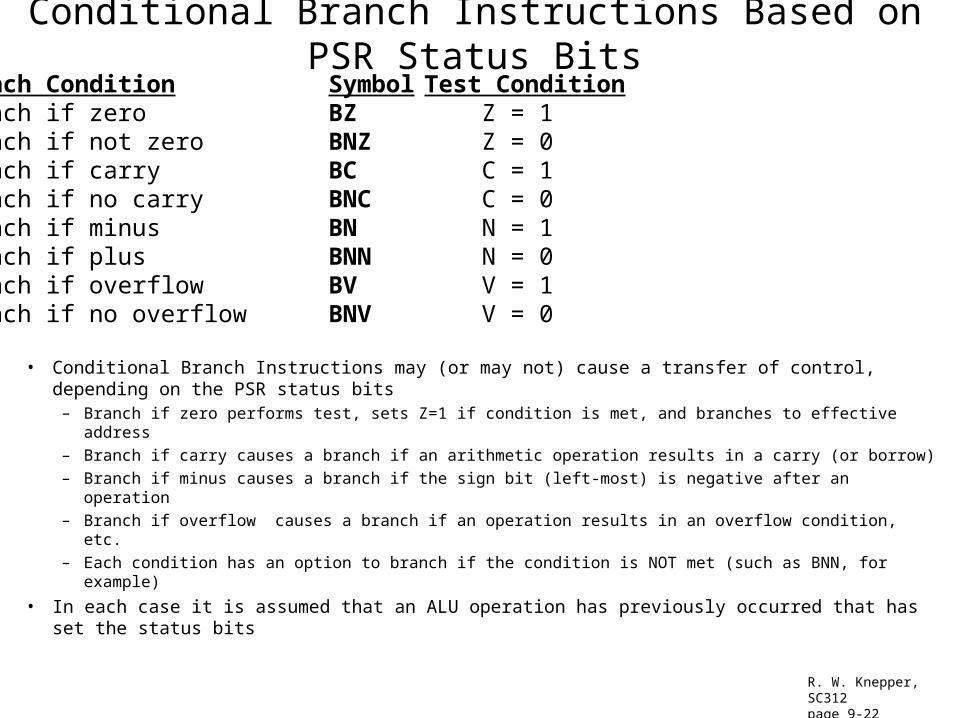
Conditional Branch Instructions Based on PSR Status Bits
• Conditional Branch Instructions may (or may not) cause a transfer of control, depending on the PSR status bits
– Branch if zero performs test, sets Z=1 if condition is met, and branches to effective address
– Branch if carry causes a branch if an arithmetic operation results in a carry (or borrow)
– Branch if minus causes a branch if the sign bit (left-most) is negative after an operation
– Branch if overflow causes a branch if an operation results in an overflow condition, etc.
– Each condition has an option to branch if the condition is NOT met (such as BNN, for example)
• In each case it is assumed that an ALU operation has previously occurred that has set the status bits
Branch Condition Symbol Test ConditionBranch if zero BZ Z = 1Branch if not zero BNZ Z = 0Branch if carry BC C = 1Branch if no carry BNC C = 0Branch if minus BN N = 1Branch if plus BNN N = 0Branch if overflow BV V = 1Branch if no overflow BNV V = 0
R. W. Knepper, SC312page 9-22
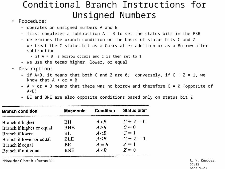
Conditional Branch Instructions for Unsigned Numbers• Procedure:
– operates on unsigned numbers A and B
– first completes a subtraction A – B to set the status bits in the PSR
– determines the branch condition on the basis of status bits C and Z
– we treat the C status bit as a Carry after addition or as a Borrow after subtraction• if A < B, a borrow occurs and C is then set to 1
– we use the terms higher, lower, or equal
• Description:– if A>B, it means that both C and Z are 0; conversely, if C + Z = 1, we know that A < or = B
– A > or = B means that there was no borrow and therefore C = 0 (opposite of A<B)
– BE and BNE are also opposite conditions based only on status bit Z
R. W. Knepper, SC312page 9-23
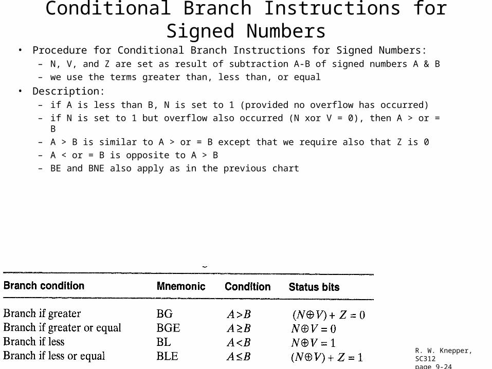
Conditional Branch Instructions for Signed Numbers
• Procedure for Conditional Branch Instructions for Signed Numbers:– N, V, and Z are set as result of subtraction A-B of signed numbers A & B
– we use the terms greater than, less than, or equal
• Description:– if A is less than B, N is set to 1 (provided no overflow has occurred)
– if N is set to 1 but overflow also occurred (N xor V = 0), then A > or = B
– A > B is similar to A > or = B except that we require also that Z is 0
– A < or = B is opposite to A > B
– BE and BNE also apply as in the previous chart
R. W. Knepper, SC312page 9-24
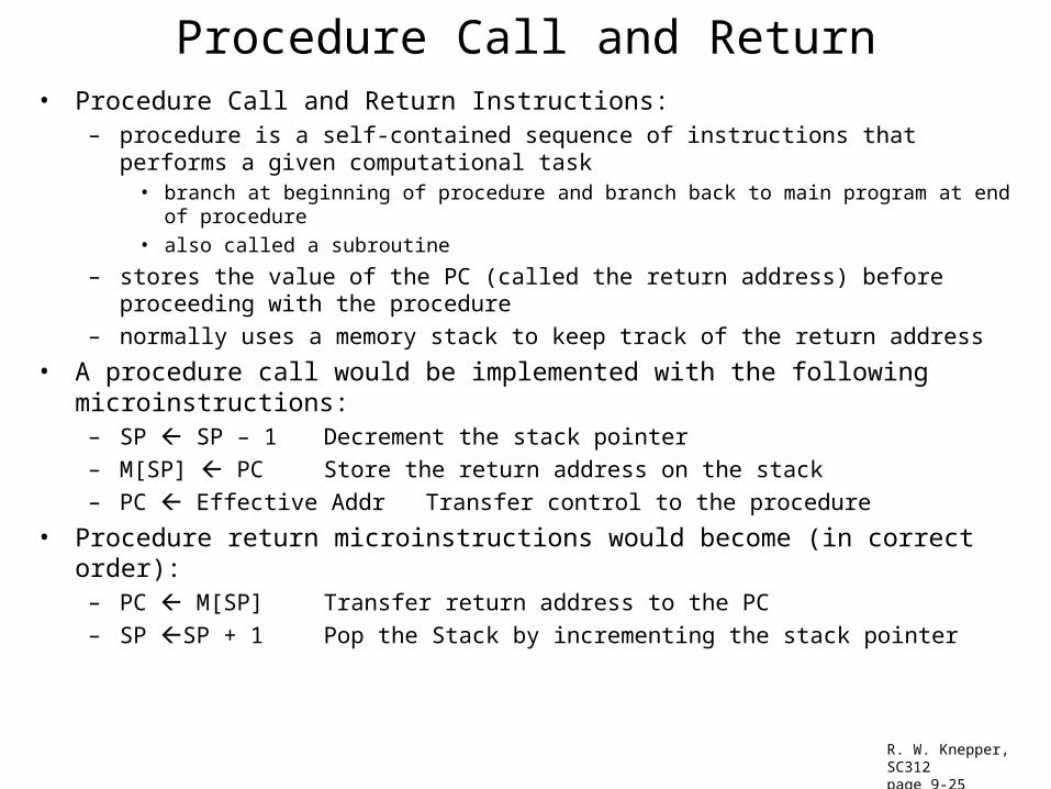
Procedure Call and Return• Procedure Call and Return Instructions:
– procedure is a self-contained sequence of instructions that performs a given computational task• branch at beginning of procedure and branch back to main program at end of procedure
• also called a subroutine
– stores the value of the PC (called the return address) before proceeding with the procedure
– normally uses a memory stack to keep track of the return address
• A procedure call would be implemented with the following microinstructions:– SP SP – 1 Decrement the stack pointer
– M[SP] PC Store the return address on the stack
– PC Effective Addr Transfer control to the procedure
• Procedure return microinstructions would become (in correct order):– PC M[SP] Transfer return address to the PC
– SP SP + 1 Pop the Stack by incrementing the stack pointer
R. W. Knepper, SC312page 9-25
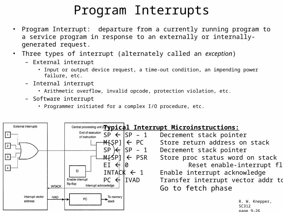
Program Interrupts• Program Interrupt: departure from a currently running program to a service program in
response to an externally or internally-generated request.
• Three types of interrupt (alternately called an exception)– External interrupt
• Input or output device request, a time-out condition, an impending power failure, etc.
– Internal interrupt• Arithmetic overflow, invalid opcode, protection violation, etc.
– Software interrupt• Programmer initiated for a complex I/O procedure, etc.
R. W. Knepper, SC312page 9-26
Typical Interrupt Microinstructions:SP SP – 1 Decrement stack pointerM[SP] PC Store return address on stackSP SP – 1 Decrement stack pointerM[SP] PSR Store proc status word on stackEI 0 Reset enable-interrupt flip-flopINTACK 1 Enable interrupt acknowledgePC IVAD Transfer interrupt vector addr to PC
Go to fetch phase