Embed Size (px)
Citation preview

• CJLDHAM
Miners Cap Lamps
and
Charging Equipment
INSTRUCTION
MANUAL
OLDHAM BATTER1ES LTD
Denton Manche:ster M34 3AT England
Telephont> 061·336 2431 Tel~x 668321
Cabl~s OLDHAMS DENTON
. ..
•

• 11
,•
OLDHAM TYPE G HEADPIECE
The basis of the headpiece is a plastic moulding, in which some of the internal connections·. are integral with the moulding. A selector switch is incorporated, which can switch on either a main bulb or a pilot bulb when the switch knob on the outside of the housing is turned. The switch blade can .be brought into contact with either the small bulb switch connection or the large bulb switch connection, which lead to the tips of the two bulbs. The main bulb is screwed into the reflector and is.held in a focussed posit:lon (determined at the time of fitting the bulb) with a circlip which connects to one of the cable termination points. The small bulb holder is positioned at the top of the headpiece, being connected internally to the cable terminatio,. The reflector fits over the small bulb and has a rubber sealing channel around the rim to seal against the headpiece glass.
When the annour plated headpiece glass is in posit:k>.n over the reflector, a plastic lens ring is screwed on to secure it firmly in place. The lens ri~g is located in position by a ~pecial triangular headed lock pin that fits into a countersunk hole and then enters one of the slots in the lens ring~ To . conform with the requirements of the Safety· Lamp Approval, the countersunk hole enclosing the lock pin must be filled with wax supplied by the manufacturers •
Battery recharging is effected through the headpiece. The positive charging contact is a stud placed just behind the lens ting on the base of the headpiece~ Beneath the cap clip at the rear of the headpiece is ·a . recess in the moulding. At the bottom of this recess· .' is the phosphor bronze negative contact, and on top of ., this, the lock barrel.~ To the right of the barrel is fitted the lock spring which prevents the barrel being turned except when the charging key is used •. The screw and the nut that hold. :the -cap clip in position have ' specially slotted hea~s so that they can only be unscrewed by a special key. In addition, the nut should be soldered after tightening.
\

.... /' Between the cap clip and the lock pin housing is a metal outlet gland through which the cable is taken from the headpiece to ~he battery.
The headpiece must be kept sealed and only opened by and authorised person in the Lamproom. To dismantle the headpiece, the wax over the lock pin should be scraped
·out. The lock pin can then be screwed out by turning in an anti-clo~kwise direction with a special turning key provided. The lens ring can then be unscrewed and removed together with the glass. The lens ring, glass ·and sealing channel around the.reflector should be scrutinised for cracks or other weaknesses which might adversly effect the seal·ing of the headpiece.
The main bulb and the reflector can be removed to reveal the interior of the headpiece, giving access to
·all the interior connections, the pilot bulb and the switch. If necessary the switch blade can be moved by loosening the grub screw that retains it. A plastic sleeve covers the switch blade body to prevent accidental short circuits during maintenance.
In carrying out repairs to the headpiece, only the small insulated screwdriver should be used, as this allows the screws to be secured tightly enough without fear of a short circuit or other damage. Once the nature of a fault has been determined, and the actual repair has begun, the switch should be placed in the off position. If a bulb is being replaced it should be tested in the headpiece.before· final re-assembly to verify that it ·will light. When closing the headpiece it should be ensured that the sealing channel is correctly fitted around the reflector. The location of the reflector is by two projections which fit either side of the pin that rests against the envelope of the pilot bulb. The lens ring shou1d be screwed down firmly and the lock pin placed so that it fits into one of the recesses of the lens ring.and firmly screwed home. The countersunk hole in the locking boss should then be filled with the special sealing wax.
It is essential ~hat all contacts in the headpiece are tight, so that no resistance is developed which might increase the time necessary to obtain an effio·ient charge or might reduce the light output of the lamp. In order to obtain the maximum light possible the 1outside of the lens glass should be cleaned regularly,
. 42-

CHAAGIHQ CIRCUIT LAMP CIRCUIT
/r. -·~·-~RACK NEGATIVE
FILAMENT SWITCH '
\
Fig.G2
INTERIOR OF TYPE G HEADPIECE
RACK POSITIVE
Fiq. Gl
ELECTRICAL. CONNECTIONS
FOR TYPE § HEADPIECE
PIG. G3 ASSEMBLY OF.RING, GLASS, CHANNEL, BULB & REFL~TOR
FOR TYPE G HEADPIECE
N~ COMPONENT CODE N° I HEAOP1ece: SHE'-L 'l. 001. 01
2 BE?S\. RIM~ 2.0IG. 21 3 L&NS (HEAPIE~E lqLRSS) 2. 001. 31 4 LOCK Plrt 2. 003. 28 s SWITCH ~NOB 2. OOG. 12
~ cJ ;r ~@ ~
' SWITCH MNOB WASHER 2. 003. 11 7 SW\TCH BLADE 2. 009. It a SWITCH BLAOE COWL 'Z. 00~ l'l 9 lQRUB SCREW 2. 00,, 15 10 CAP CLIP i. 001. 44 II CAP CL.IP SCREW 2. 002. IS 12 CAP Cl.IP NUT 2. 001. 13 13 SPRINQ WASHER STE!iL. 2 ooe. " 14 L.OCt< SPRll'tG 2. 002. 34 15 LOCK BARREL. i. OQl. .34-
'' WED~E 2. 002. 08 17 LOCK CONTACT i. 001. 10 18 LOCK CONTACT SCRew 2. ooa. 1s 19 CHAA~IN~ CONTACT SCREW ~- 004. 15
20 CABLE OUTLET CLAND. 2. 001. 20 21 SEALINCi CHANNEL 2. 004. " ~
22 AEF\.ECTOR ASSEMBLY SPOT 2 028 2T u REFLECTOR AS9EMBL.Y SEAM t. 02'7. 27
l~ 'Z3 REFLEC'TOR CIRCLIP WITH FLEXIBLE CONH. 'l. 039. 55 24 L.AR~E BULB SOCKET BLOCK 2. 001. 08 -25 LAR~E BUl.B SOCKET SCREW 2. 005. 15 2, SMAl.I. SUL 8 90CKEl ASSEM8L Y i. OOS. H 2'7 '-AR~E BUL.8 Al'40 SWITCH CONN. ASSEMBLY 2. 012. 23 28 SMALL BULB AND SWITCH COHl't ASSEMBLY 2. 005. 23 29 SWITCH COl'tNECTIOM 2. 001. 10
30 3/1~· 8. HI! SCREW 2. 007. 15 a1
~· MAIN BULB 4V. l·OA 2. 006. 30
32 PILOT BULB 4'1. 0·4GA 2. 001. so
WHEN O~OERIN§ PLeAse guoTE CODE flt9 f
J--A
TYPE .G. HEADPIECE PARTS

CHARGlH~ C\RCUIT
LAMP CIRCUIT
Fii.AMENT SWITCH
\
Fig. G2
INTERIOR OF TYPE G HEADPIECE
RACK POSITIVE
Fig. Gl
ELECTRJCAL. GONNECTIOMS
FOR TYPE. 9 HEADPIECE
Fi\g. G3
ASSEMBLY OF RING, GLASS, CHANNEL, BULB & REFLECTOR FOR TYPE G HEADPIECE (Prefocus· Bulb)

J----® A --·--· __ IV\
L=.'!f7 v
"' COMPO~HT CODI ~!I I HEAOPU!CG!: · SHl!b&. I. 001. 01 2 aucn .. Al~ I. 011.11 3 UIMS (M&APltiCE QbASS1 I. 001. 81 4 LOCK Plrl 2.001.11 5 SWITCH K..08 a. aoa. 11 G SWITCH ""OS WASHER I. OOS. 11 7 SW\TCH 8&.AO& I. 009. II a SWITCH BbAOEi COWb I. 004. 12 9 GRUB seAew 2. OK. Hi 10 CAii Cl.IP I. 001. 44
" . CAP Cl.IP SCREW t oot. 1s 12 CAP C\.IP f"IUT i. 001. ll 19 SPRlNQ 'lllASHER 9TiEJI .. · I 001. II 14 l>OCt4 8PRIMGi. 15 1.0CK BARREL. ,, WEDQE 17 LOCK CONTACT 18 LOCK CO~TACT SCREW 19 CHAAc;INCO CONTACT SCA!W
20 CAB\.! OUTLET CbAMC 21 SEAL ING CHAM1'4EL 22
i--PREFOCUS REFLECTOR ASSEMBLY SPOT
23 PAEFOCUS REFLECTOR LEAO --24 L.AR~e BULB---SocMET BLOCK 25 \.AR~E BUl..B SOCKET SCREW
2G SMALi.. SUL B 90CKE91' ASS&MBL Y
27 l.AR~E BULB AHO SWITCH co""· ASSEMSl.Y 29 SMALL BULB AND SWITCH COHtt ASSEMBLY 29 SWITCH C01"4NeCTIOM
~o 3/11• 8. HI? SCREW
31 MAU1 BULB .. V. l·OA PREFOCUS 32 PU.OT 8UL.8 4'4. 0·4GA .
WHEN OROERIN§ PLEASE guoTe CODE N9
TYPE 1
G,, HEADPIECE PARTS IPREFQCUS BULB
r. ooe. 94 I; OQl. 54 2. 002. 06 I. 001. 10 e. oos. " i. 004. 15 2. 001. 10 2. 004. lf 2. 048. 55
2.050. 55 2. 001. OB 2. 005. IS I. 008. 29 2. 012. 23 2. 005. 23 r. OOA. 10 2. 00'7. 15
2. 012. BO 2. 001. ao
T
..

·-
HEADPIECE AND CHARGING CONTACTS .
Fig. GS KEY CHARGING SWITCH DISASSEMBLE D.

N~ COMPONENT
123 CABl.E OUTLET ~I.AHO
124 CABL.E 125 CABLE (iRIP
12G SEAl.ll"t<i COl.LAR
129 'TERMINAl. TAt;.
131 BATTERY CO"'ER ASSEMBLY
\32 CABl.E GL.AHD 133 AN~l.E C'-AMP 134 ANCil.E CL.AMP RIVET
135 LOCK C~AMP BUSH ASSV
13G LOCKIN(i PLATE 137 LOCK DEVICE SC:REW 139 ll'tSULATIN~ PAD. P.Y.C. 139 BRCK PLATE 140 NUMBER CHECK 141 FLAT HEAD Rl"ET 142 CABLE 1.0CK
159 PLAIN WASHER 150 TERMll'IA'- TAG. SMAL.L
ISI TERMINAL TAG. L.ARGE
152 TERMINAL SLEEVIN~ REC 153 TERMINAL SLEEVING Bl.ACK 154 FUSE ( EHCAPSUl.ATEDl
1!7 HEX. TERMINAi. NUT
ISG SHAKEPROOF WASHER
170 !o\E'I' l=OR SLOTTED SC~EW.
WHftt OR0:;~1NG Pt.ERSE
·• Cl
CODE N~
l?. 001. 20
2 041.23 2 008. IG 2. Oa4 I~
~ 002. IG
2 013. 55 2 003. 20 2. 003 34 2 004. 29 2 009. 23 2 004. 34 2 013. 15
2 ODS. 33 2 006.33 2 003. oa 13 05. 01. 01. 0 2. 011. IG
I. 20. OS:.I. ~.on SG 2 on sc, 2 OH. ~a. 2. oi9. s; 4 553 23 4. 5!4. 10 3. 20. 0, I
2 008.51.
QUOTE CODE "~ t
------------Q ~
-@
-------~ "? ~
CABLE & BATTERY COVER COMPONENTS FOR TYPE 'G' HEADPIECE
WITH TYPE 1T
1 BATTERY.

OLDHAM TYPE 'T' BATTERY
The battery consists of two cells assembled in a polycarbonate container. The cells are self-contained and separated from each other by a partition which forms an integral part of the body and acts as a reinforcement for the container. The cells are in series, the positive post of one cell and the negative post of the other ?eing connected by a special encapsulated fuse.
The positive plate in each cell is of rectangular tubular construction. The active material is· packed around antimonial lead spines and retained by tubes of perforated P.V.c. with an inner sleeve of woven glass wool. The negative plates are flat pasted, the grin being in the form of a lattice.
The separators are of patent synthetic cqnstruction and highly absorbent so that they hold 8.5 per cent of the total acid in the cell, leaving only a small volume of free acid above the plates. Th:? separator is nesigned to fit tightly between the plates, and the amount of free acid is so small as to make the battery unspillable when topped up correctly. A separator of this type is extremely efficient at the rate of discharge used in cells for mine-lighting duty.
The electrolyte is dilute sulphuric acid, the specific gravity with the cell in a fully charged condition being between 1.2eo and 1.300. The level is maintained by the addition of small quantities of distilled water at regular specified intervals.
At the front of the battery are two filling and vent holes, one for each cell. The venting arrangement is of a labyrinth design to prevent the small amount of free electrolyte from spilling from the battery. The design of the filling hole is such that it is tapered outwards and sloping upwards to reduce the possibility of the holes becoming blocked. If any blockage occurs, this will usually be forced out by the build up of gas pressure inside the cell during charging. Any serious blockage should first be loosened with the aid of a wire before charging, taking care not to push the blocking material into the cell.
The transparent container allows the electrolyte level to be clearly visible, and the absence of any removable plug considerably simplifies the p~ocess of checking levels and topping up.
The cell lid is also of polycarbonate and is sealed .into the top of the battery box. Where the terminal posts come through the cell lids they are sealed by a double cone grommet to eliminate any danger of electrolyte leakage. The cable leads are secured to the outside terminals by 4 BA nuts. The positive lead is connected to the right hand side of the battery.
7

It is advisable to ensure that the bottom terminal nuts on each of the four posts are kept tight to maintain an effective post seal. The cable terminal tags and fuse should be placed above the bottom nut and secured by a second terminal nut. A protruding boss adjacent to the negative terminal prevents the larger positive cable terminal being incorrectly placed. Shakeproof washers should be placed under the cable terminals and the leads must be correctly aligned before the nuts are tightened. The intercell connection is made by the fuse, fitted with spade terminals. A plain washer should be placed between the second nut and the fuse terminal. The special battery terminal key should be used for the terminal nuts.
The battery cover is made of stainless steel with an angle clamp at one end to secure beneath the rim of the battery lid. When the cover is positioned on the top of the battery it is further secured by a lock device which fits at the end opposite to the angle clamp. The lock device fits over the end of the cover, and is secured in position by a ~lotted screw. After the screw is tightened, the bush is filled with wax to detect any unauthorised person tampering with the battery.
The belt loops are moulded integrally as ~art of the container back wall.
The cable enters the battery cover through an aperture on the top. It is then threaded through an alkathene cable lock, in which the cable is doubled. At the point where it enters the cover the cable is protected by a neoprene cable gland.
To remove the battery cover, first scrape out the wax seal from the lock device and take out the slotted screw with the key provided. This enables the lock device to be detached and the cover removed. When replacing the cover fit the angle clamp beneath the rim on the battery lid to the left of the vents. Ensure that the cable leads lie properly on the battery top without being trapped, particularly making sure that the negative lead is not compressed beneath the cable lock. Press down the cover, fit the lock device and screw to the cover and battery and seal with wax.
The battery cover should be tested immediately after reassembly on to the battery, and at prescribed intervals, to determine that there is no electrical leakage beneath them. This is best done with an Oto 6 voltmeter (200 ohms per volt), or the Oldham lamproom test unit. The test can be carried out on the frame with the charger switched on, by putting the voltmeter positive lead to the positive spring contact on the charging frame, and the voltmeter negative lead to the battery cover. This will reveal a •negative' leakage to the battery cover. Reversing the leads, and putting the voltmeter negative on to the charging frame negative key, will reveal any •positive' leakage. If either of these faults is found the cover should be removed an3 the fault rectified.
' .<t

Reflectors
Two types of reflectors are available for use in Oldham lamps. These reflectors consist of a plastic moulding which has been given an extremely efficient aluminium reflecting surface by a vacuum deposition process and protected by a special non-tarnishing varnish. Both reflectors have provision for pre-focussing of the main bulb and have an aperture for the pilot bulb.
The spot reflector has a reflecting surface specially processed to provide a high intensity spot. The beam reflector, in addition to providing a strong beam of light also gives a high degree of surround illumination.
The achieve a correct light distribution, a special protective varnish has been used. No attempt should be made to polish the reflecting surface otherwise the light output will be seriously affected. Cleaning can be carried out by washing in soap and water (not detergent) and rinsing in clea~ water. A light wash leather or soft cloth can be used to remove any marks left by the washing process.
Every time a reflector is changed, it is advisable to renew the sealing channel and also the large bulb and switch connection assembly to ensure there is sufficient tension in the coil spring. This will enable contact to make a good electrical connection with the bulb.
Special attention should also be paid to the negative charging contact beneath the lock barrel. Any excessive wear or contact resistance will affect the charging of the battery and consequent performance of the battery.
Bulbs
The 4v. 0.9 or l.O amp main bulb is Krypton filled and is manufactured in accordance with BSS 535. The pilot bulb is rated at 4v. 0.46 amp.
CABLE FOR OLDHAM CAPLAMPS
The cable is of a spirally wound short lay type to permit maximum flexibility. It is manufactured in accordance with BSS 4945 and is rigorously tested at the factory of the lamp manufacturer before being.despatched.
Within the headpiece the cable leads are made off with identical terminal tags, the cable end·s being covered with lengths of coloured P.v.c. Inunediately above is a cable grip fixed to the cable and covered with a rubb.er. sealing collar. This lodges under the metal outlet gland of the headpiece. In this way the cable cannot be pulled out of the headpiece.
At the battery end, the cable enters the cover and it is· then threaded through an alkathene cable lock, in which the cable is doubled. At the point where it enters the cover the cable is protected by a cable gland of neoprene to prevent danger of the cable wearing during service.
I·f a lamp fails and the trouble cannot be .located in either the battery or the headpiece, the cable should be examined for cuts and abrasions which may have ~evered or short circuited the conductors. The cable can be tested for internal damage by flexing at various points.
\.0

conswnption of water is observed. Normally batteries should require topping up with approximately 7 cc per cell per week.
Overdischarge, double shifting or undercharging can seriously affect the battery performance and life.
All the above precautions should be diligently observed to obtain the best performance from the battery and to maintain its unspillability. If spilled on cotton clothing, electrolyte will decompose it unless neutralised by an alkaline such as household aimnonia. It has less affect on woollen cloth but, in the event of spillage, the electrolyte should still be neutralised.
RECONDITIONING CHARGE
Sometimes it is reported that the lamp will not keep burning for full working shift. If the fault can be attributed only to the loss of capacity of the battery, it is not necessarily because the battery is exhausted and needs replacing. It may be that, in the course of repeated and consecutive long discharges, it has not been able to receive adequate charge. In such instances, or if the battery plates have become partly sulphated due to undercharge or faults in the charging system, a constant current reconditioning charge should restore th.e battery to useful working conditions.
For this purpose, the constant current nursing frame has been specially designed. One of these charging frames is desirable in each lamproom, to enable the best performance to be obtained from an installation of caplamps. A nursing or reconditioning charge cannot be given on the constant potential charging equipment.
The lamp should be re-assembled after preliminary examination for minor faults, as the series charge can be given through the headpiece charging contacts in the normal way. If during this examination one or both cells give a zero reading on the voltmeter, it must be assumed that there is a physical break in that cell, i.e., broken post. Under these conditions a reconditioning charge is not advised, as arcing at a broken post may ignite hydrogen gas in the suspect cell.
The charge should be 0.5 ampere for thirty hours. The electrolyte level should be· adjusted before, during and after the charge. If the battery fails to give a satisfactory burning time after this period, and the fault can not be traced to any other component, the battery may be replaced.
VERY IMPORTANT
It is essential that only a clean cloth or tissue, moistened with water if necessary, be used for cleaning the top of the battery. Detergents or chemical sprays must not be used for cleaning or other purposes
tl

THE OLDHAM CAP ~ . ~ ... r FHOTOME'l" ER TY.PE CL
FOR QUICK AND ~CCURATE CHECKING ON MINERS' CAP LAl'lP ...,I ~H'r OUTPUT
The importance o f lamproom photometric meas.uremt.~\'tt 1as been appreciated f or many years b y Oldham. The.r , ere tlK~ i:irst to institute regular photometric control at mine~ and to deve lop a photometer necessary to carry out this wor~. ~~e
latest instrument is ;:o si911ed as the result of this e"(:pei:· ··~nee and is in l~ne with the general high standards of Oldram Products. It is fully portable and indicates mean sph~rical candle power (m.n. c.p . ) or l umens directly.
The photometer con~ists of a hollow cube of polished oak wi th a special surfaced w1ite integrating int erior. A window is provided for the application of the cap lamp headpiece, and a screen i n front of photocell prevents direct incident light falling m1to the cell. A selenium type photocell has been specially modifJ.ed tL~ give increased stability. The microammete1 is calib rated d n.ect. ly in mean spherical candle power and lumensr ranges of 0.4 mean spherical candle power and 0-50 lumens are provided .
•r he c ubical form o :t; photometer was decided upon in preference to the spherical form only after a considerable amount of research as the latter has no advantage when the pos i tion of the light source is the same for all measurement s. Thi s ·has been verified in that case of the Oldham photometer by :mca.'3urements o~ extreme accuracy. As both types of photometer are capable of giving equally ~ccurate results. The c ubical type is preferred as being more convenient in use and more portabl e than the spherical type.

Filling & Venting Aperture
Transparent Poly ea rbonate
Container ------,...----
Battery Terminals
Post Seal
One Piece ---Polycarbonate
Cell Lid
Non-Spill Device
Integrally ·---- Moulded
Belt Loop
Tubular Pg Positive Plate
Antimonial Lead Spine
Active Material
Woven Glass Fibre Inner Sleeve
I
Negative Plate I -+---+---Perforated P.V.C.
Outer Sleeve
~Absorbent
Fig T1 Sectional Type T Battery \3
Separator
Shim Separator

0 ©
Fig.T2 BATTERY COVER ASSEMBLY
TYPE T BATTERY l4-

INSTRUCTIONS FOR THE FILLING AND CHARGING OF DRY CHARGED 'T' OLDHAM CAP LAMP BATTERIES
1. Do not remove the tape from the vent holes until the battery is required for use.
2. Fill each cell of the battery with 180 ml pure dilute sulphuric acid of specific gravity 1.260 corrected to 60° F /l 5°C* •
3. Allow to stand for a period of not less than one, nor more than 3 hours.
4a. Charge at l.Oamp for 20 hours on a constant current or charging frame. . 4b. Place on the standard constant potential chargin9
frame and charge 5.0 volts for 24 hours.
5. Take off charge and allow batteries to stand for 24 hours.
6. If necessary, top up with further acid so that the electrolyte is level with the top of the separators.
7. From then onwards all charging will be at the normal rate and only Distilled Water must be used for subsequent weekly topping-up.
*NB The specific gravity of a given concentration of sulphuric acid varies with temperature. Normally all specific gravities are stated corrected to 60° P/15°c. To correct for temperature, an addition or subtraction from the observed hydrometer reading must be made.
To obtain the correct specific gravity if the temperature is above 60° F/15oc add 0.004 for every lOoF, or o.007 for every l0°c rise in temperature to the observed hydrometer reading. If the temperature is below 60° F/ls0 c this correction should be subtracted from the observed reading.
For exam2le:- Tem12erature Observed Reading corrected Reading
so°F/lo0 c 1.264 1.2·60
60°F/1S0 c 1.260 1.260
70°F/21°c 1.256 1.260
800F/27oC 1.252 1.260
90°F/32°c 1.248 1.260
\ s-

CARE OF THE OLDHAM TYPE 'T' CAPLAMP BATTERY
Proper care for the battery is the most important part of lamproom procedure if operation is to be efficient and costs economic.
At the end of charge of a battery small amounts of oxygen and hydrogen are liberated from the electrolyte and escape through the vent holes. This causes a small loss of electrolyte which must be replaced. The electrolyte level .is clearly visible through the transparent container and the necessary distilled water should be added every week, an equal number of lamps being checked each day. The work should be divided between the shifts, and the checking of each battery recorded by crossing out the corresponding number on a special 'topping-up' sheet. . These sheets are obtainable from Oldham and can be clipped to the topping trolley by special clips. In many lamprooms it is usual for the different shifts to cross o~t' in different colours, so that a complete record can be kept.of the work done, and the man by whom it was done. The head lampman should file these sheets after noting that all the numbers have been crossed off. The best time to top up is when the lamps are in a near.to fully charged condition
The Oldham topping trolley or topping device can be used. The former is wheeled to the frame and the battery to be topped up is placed on the lead-covered platform in the holder provided. The topping gun is swung into position and distilled water added with the gun, until the electrolyte is level with the top of the separators. The battery should be in the vertical position. Alternatively, the battery can be topped up with distilled water from a plastic topping up bottle.
The battery terminals should be smeared lightly wi~h petroleum jelly to prevent any possible corrosion and the terminal nuts checked periodically for tightness. This will ensure that there is no high resista~ce causing poor light output or inadequate charging.
The batteries should never be left in a discharged condition. corrept charging is essential if maximum light output and battery life is to be obtained.
With standard constant potential charging equipment the recommended charging voltage as indicated by the charger voltmeter is s.o. Where automatic voltage control (A. v .c.) is· installed, however, this vol ta:ge can be r·educed by·o.os. In tropical climates it is also generally advisable to reduce the voltage by a.as. As a rule, the charging voltage should be set as low as practicable to obtain the full discharge throughout the working shift. Overcharging can damage the battery. An indication of overcharging is given w'hen excessive
\~

PHOTOMETRIC CONTROL
If a lamp installation is to be efficiently maintained it is advisable that a regular system of photometric measurements of each lamp should be in operation. Oldham C~p Lamps, although normally giving a very high standard of useful light, are obviously subject to deterioration due to fair wear and tear of several of the parts, and ultimate failure of the batteries. The extent to which the light output has diminishen may not he aporeciated by the lampmen or the lamp users particularly as it occurs gradually and over a long period. The only reliable method of determininq the efficiency of a cap lamp is by using a photometer, and Olnham havefleveloped a useful, portable instrument especially for such determinations. It is advisable that all cap lamp installations should have such an instrument and use it in an approved, regular system.
Several schemes for photometric control have been tried, but the following is the one found to be most successful by Oldham engineers:-
The tests are taken in numerical order every calendar month, and one quarter of the installation is done each week. They are usually confined to a maximum of five days in the week, so that time is left for investigating the doubtful cases. Tests should be started about half an hour after the end of the normal working shift, to allow a factor of safety on normal operation.
The men should be instructed when tests are to be made, to leave their lamps burning when they hand them in, or in self-service installations instructions should be posted informing the men that their lamps must not be switchen ·off or put on charge. The batteries should be put in their normal positions and the headpieces and cables allowed to hang down, It is then a simple matter for ~he lampmen to carry out the tests required.
The meter scale of the Oldham cap lamp photometer is arranged to read directly in mean spherical candlepower on the top scale (each large and numbered division being 1 m.s.c.p.), and in lumens output on the bottom scale. Each lamp is teste~ simply by holding the headpiece against the glass window in the side of the photometer cabinet until the needle of the meter steadies.
The results obtained should. be recorded on the Oldham photo-·metric test sheet, designed for the recording of 100 tests, with abbreviated references for the correction of faults. These records can be entered up in a card index system or book, as desired, together with the records of new parts added to the lamp.
Lamps failing to reach a predetermined minimum M.s.c.P. should be put on one side for examination after the measurments are complete. Some indication of where the fault is likely to lie can often be gleaned by studying the previous history of the lamp from which the age of the battery and bulbs can be ascertained.
Photometric c~ntrol provides the only real check on the standard of maintenance in the lamp room.

THE OLDH..!\M LAMPROOM TEST UNIT
Designed by the Oldham Electrical Research Department to enable all lamproom electrical measurements to be carried out with one instrument.
The followi ng tests can be carried out with the Oldham Larnproom Test Unit:-
Actual voltage at charging contacts
Current consumption of the lamp bulb
Voltage at the lamp headpiece
Electrical continuity of poor electrical contac ts, both on the charging fra~e and inside the lamp
Positive and negative e lectrical leakage test
The Oldham Lamproom Test Unit houses instruments of the correct specification to enable the various tests to be carries out with the greatest possible accuracy. Voltmeters a..~d ammeters of incorrect resistance or with unsuitable graduations can give rise to substantial errors due to the relatively small voltage and current involved .
The regular use of the Unit, according to the instructions provided with each Unit , will impr ove efficiency and considerably simplify fault-finding and gene ral maintenance work in the lamproom.

One of the most important tasks in the efficient running of a lamproom is the accurate measurement of voltage and current values on the charging frame and battery throughout the 24 hours of the day.
These measured values are very small. For example, the actual charging voltage applied to the c_aplamp battery is the difference between the prescribed voltage on the charging frame and the rising terminal voltage of the battery. This has a maximum of approximately 1.3 volts at the start of the charging cycle and is in the region of 0.1 volt at the end.
Similarly the charging current varies between a maximum of approximately 1.5 amperes at the beginning of charge, and O.l to 0.2 amperes (or 100 to 200 milliamps) at the end.
Variations in light output of the order of 0.2 m.s.c.p. as an average over the whole of the installation can differentiate between a good and bad lamproom. The current taken by a bulb never exceeds one ampere, and to drop this current by only O.l or 0.2 amp, because of, say, a bad contact, can reduce the light output to the point when the bulb must be changed.
The above statements show how important it is to ensure that, whilst engaged in measuring any values in the lamproom, there are no losses in any part of the circuit of the testing apparatus.
Losses in the circuitry are· not measured on meters in use, and this means that as far as the value shown on the meter is concerned, the rejection value of the component has been reached, and it should then be discarded. This can prove to be rather costly, so the possibility of meter connections having a contact resistance must be avoided.
Meters have their own internal resistance values and it is important that the correct value of meter resistance is used for the specific task in hand. For instance, a 100 ohms per volt instrument could in some cases indicate values which are too high, and yet a 100 ohms per volt meter would produce no readi~g at all.
The Oldham Lamproom Testing Unit eliminates all these undesirab1e faults, and contains all the instruments necessary for every 1amproom measurement (with the exception of photometric values) in one box. The unit is designed so that tests are done 9uickly and with the minimum of connections to be made. The method Of operation for the various tests are as follows:-
\q

To Test for Electrical Leakage un the Battery Top while the lamps are on the charging frame.
Connect the negative terminal on the test me~er to the negative charging key on the frame. connect the positive terminal on the test meter to the positive spring clip on the frame_ With the test lead connected to the wander plug terminal, touch all the battery covers in turn. By using the selector switch both
·negative and positive leakage can be tested without changing the conn~ctions.
To Test for Charging contact Voltages
Connect the positive and negative termin9ls to the appropriate contacts on any unoccupied ~osition on the frame, and depress the Test Switch. The voltage across the contacts will then be shbwn on the test meter, and thus the voltmeter on.the charger can be checked and set correctly.
IMPORTANT
The charger vol tineters should be calibrat.'e'"d ·at the working values and· any error at zero ignored.
To Test Bulbs for Current Rating
Screw the bulb into the socket provided. Take a fully char~ed caplamp, put the hefadpiece on the contacts provided on the tester. Depress the Test Switch, rotate the variable resistance (Bulb yoltage Regulator) until exactly 4 volts are indicated· on the voltmeter. The current reao~ng on the ammeter is then showing the acual rating of the bulb. (It is not necessary to provide any other source of current other than the caplamp, unless the c~~lamp battery is not fully charged, and this will be shown by the inability to reach 4 volts on the meter).
The Voltage at the Headpiece End of the lamp will indicate if any bad contacts are causing voltage drops in the lamp circuit. This can be teste~ by putting the headpiece of the lamp on the charging contacts of the tester, with the bulb burning, and by depressing the Test Switch.

Bad electr~cal contacts which cause flickering lights can also be detected by the above test. The lamp should be switched on and left for a time. Bad contacts will cause the volt~eter needle to move erratically.
Electrical Leakage Test in the Repair Room
This is a most important test and should be carried out EVERY time a battery cover has been taken off and put on again in order to detect a trapped or pinched cable on which the insulation may have been broken.
An external current supply is not required. The headpiece should be placed on the tester, charging contacts and the battery cover touched with the wander lead. By switching the Battery Leakage Switch from one side to the other, it is possible to detect both positive and negative leakage.
After a Photometric Test has been carried out, the lamps that have been put aside for low m.s.c.p. readings should first be tested for voltage at the headpiece end. In thi·s way, much work can be saved because if the voltage is sufficiently high, it can be the bulb or contacts that are at fault.
The voltage should then be tested at the battery terminals when the lamp is switched on. This is done by removing the battery cover and connecting the test unit to the terminal$ This test must not be made with the headpiece on the tester charging contacts.
A bulb should never be left in the bulb holder when measurements other than bulb ratings are made, otherwise false readings will be obtained.
The testing unit, which is precision instrument, should be treated with care. A little vaseline can be applied to the terminals to ensure that they always remain clean.

OLDHAM CAP LAMP CHARGING EQUIPMENT WITH AUTOMATIC VOLTAGE CONTROL (102 TYPE AVC)
To save labour in the lampropm and to provide an efficient method of charge, special charging equipment has been designed for Oldham lamps whereby each lamp is charged by a system of modified constant potential on a frame and charger unit, with the voltage stabilised automatically at. a preset level.
CHARGER
The charger is housed in a sheet metal enclosure which is· ·placed on top 'of the charging frame.
The charging voltage is controlled automatically over the charge cycle and is maintained at the preset value, ir~espective of the number of batteries pn charge, their state of charge or input voltage variation. The charging voltage, which is indicated by the meter on the front of the charget, is initially set to the required value by the simple adjustment of a rheostat fitted to the control panel.
The unit will correct voltage variations of up to + 1% (i.e. + o.os volt) in both tropical and temperate climates with up to 102 discharged batteries on the frame.
Once the output voltage has been set· to the correct value, lamps may be removed from, or added to the charging frame without the necessity of any further adjustments to the control unit.
The mains switch is a double pole circuit breaker, mounted on the front of the unit. The n.c. voltage is indicated on a flush mounted rectangular voltmeter with a range of 4 to 6 volts. A neon light on the front panel shows when the mains supply is switched on.

CHARGING FRAME
This is of sheet metal construction with P.V.C. covered shelves on which the batteries stand while being charged. Above each battery is an indicator which shows whether or not charge current is flowing. The negative charging contact is a switch key mounted below the charge indicator. The barrel lock behind the cap clip in the headpiece is fitted over this and, when the headpiece is turned through 180 degrees, the positive charging stud comes into;cpntact with a spring clip assembly on the frame. At,.the same time, the turning of the barrel lock brings the switch key into contact with the negative contact within the headpiece, and the charging circuit is complete.
At each charging position there is a number plate to ensure that each lamp is always charged in the same place on the.frame, as the number of the charging position will tally with the number on a specific lamp. Thus the user has no difficulty in finding his own lamp.
The shelves on which the batteries stand are covered with P.v.c. that should be regularly cleaned. If any of the battery electrolyte is spilled during topping-up this should be washed off immediately. Oil should never be used· on either the shelves or the batteries.
When a headpiece is put on to the frame the needle of the charge indicator above the lamp will swing over indicating that current is flowing and that the battery is on charge. If the needle does not move over it could indicate one of three faults: the charging contacts may be dirty, the frame connections may be loose or the fuse in the lamp may have blown.
Care should be taken that the voltage drop between the charging unit and the lamps is minimised by ensuring cleanliness of the contacts on both lamps and frames. Dirt or corrosion may introduce such a resistance into the circuit that the batteries can not be charged in the normal period. Emery cloth or other abrasive material should not be used for this cleaning: the best way of keeping the positive spring clip clean is to paint it lightly with petroleum jelly, and then wipe off. ·,_

Fig. Pl 102 TYPE AVC CHARGING EQUIPMENT

llA IN lltOTIFI811
+re OUTPUT
OUTPUT
MAl/t
llAJ/o TffA 'l;)f ()ffll'll
TllA rt.SDLCTClll
l'A/llrAL
.~ocnT
\
AUTCI
SOCKlT
I
llA UI.~
C fR CUfT 11/ICAXER
I
F.AllTH POINT
Fig. P2 INTERIOR OF 102 TYPE AVC CHARGER
AUTO TRAHSFORMUI ,..-- --- - ---~ I 110 • 120• l&Ov :
j b,,.\ .. l.,l .. ,1 • I 2~0V I
~---- -------------~
Ao
[j~,-;; -,~1 ------, IO 10 ;, I
I ;LJ ~o soso : I To aci to I 70 lo •o I I
•IOo tto Ito • "-------'
iio uo Ito L----- J
AUTOMATIC MAH UAL COHTROL CCHTllOL SOCKET SOCKET
Fl I · P3
,-,! I
i9o • ~__'1~_:.IOoj
~ · WA'r PLUG
Co
Cl
~ MAIHS i AUTO TRAMSFORMBR !
WHEl'1 REQUIREO I
b -r-,
---.... ~ ."""",....,,.---·
-Q
CIRCUIT DI~GRAM OF !OS TYPE AVC CHARGER
2-'5'"
.- VOL Tiit Tt II
NAN UAL CONT flOL
UNIT
CONTROL
UNIT
EA/IT H POI NT
YO/I
U O I 7SOY Tfl ANSFOIU/Efl
I

INSTALLATION AND OPERATING INSTRUCTIONS
OLDHAM 102 TYPE AUTOMATIC VOLTAGE CONTROL CAPLAMP CHARGING EQUIPMENT
A.C. ll0/l30V & 200/250V SINGLE PHASE 50/60 Hz
INSTALLATION
The charging unit is intenden to be mounted on top of the caplamp charging rack. The equipment should be installed in a well ventilated positon, ensuring that free access for cooling air is not impeded or restricted in any way, and as far away as possible from apparatus generating heat. The cover can be removed by lifting upwards after removing the securing screws.· The leads from the charging rack should be connected to the output of the charger: the positive being connected to the output fuse, and the negative to the centre tapping lead of the main transformer.
The mains adiustment leads must be connected to the appropriate tappings on the main and auxiliary transformer. For 110/130 volt supply·· an auto-transformer ea~ be supplien to be fitted inside the charger adiacent to the main transformer and the main and auxiliary transformer tappinqs set at 250v. The equi~ment is designed for conduit mains entry ann an earthing point is provided below the entry point.
The protection given by the circuit breaker main switch of the charger should be backen up by short circuit protection (fuses)main supply to the lamp room. Due to the relatively heavy current (maximum full loan approximately 5 amps) taken by the single phase charging units, it is advisable to limit the loan by not connectinq more than four chargers to any one circuit.
Where the incoming supply is normally three phase, a three phase/single phase transformer is required to provide the supply to the charging circuits. However in the case where the incoming supply to the lamp room is a three phase 440 volt four wire system, the charging circuits can be connected between any one phase and neutral. The total load should be balanced as nearly as possible over the three phases.

AUTOMATIC CONTROL
The control unit is mounted on a printed circuit board and has the following external connections by means of a 12 way pluq and socket.
a} An auxiliary AC supply of 15 volts nominal connected to pins 1 & 2
b) A D.c. power supply of nominally 5 volts, normally derived from the output of the battery charger and connected to pins 5 & 6 with pin 6 t he more positive.
c) The power output is taken from pins 3 & 4 with 4 the more positive . It is rated to deliver up · to 5 amps into a transductor control winding of approximately 1 ohm resistance.
d) The voltage sensing circuit is connected to pins 7 & 8. Since this circuit makes accurate measurements of the charger voltage it is c onnected d irectly to the output terminals of the charger by ~eans of cables carrying no other current .
The charging voltage is set a t 5 volts at the factory.
Adjustment of the control p otentiometer may be made by a s:crewdri ver inserted through the lower of the two holes in t he front panel of the charger. Adjustment should be made with at least ten fully charged lamps on the charging frame.
MANUAL CONTROL
Should it be required to operate the equipment under manual cont rol, the 12 way plu g shoul d be removed from the socket marked "AUTO" and inserted in the socket marked "MANUAL". The potentionrneter. mounted behind the upper hole in the front panel may then be used to vary t he transductor control winding current and thus the equipment output •
. A double pole circuit breaker is connected in the
input and a neon indicator is fitted to show when the supply is switched on. A voltmeter is fitted, connected across the D.C. output.
IMPORTANT
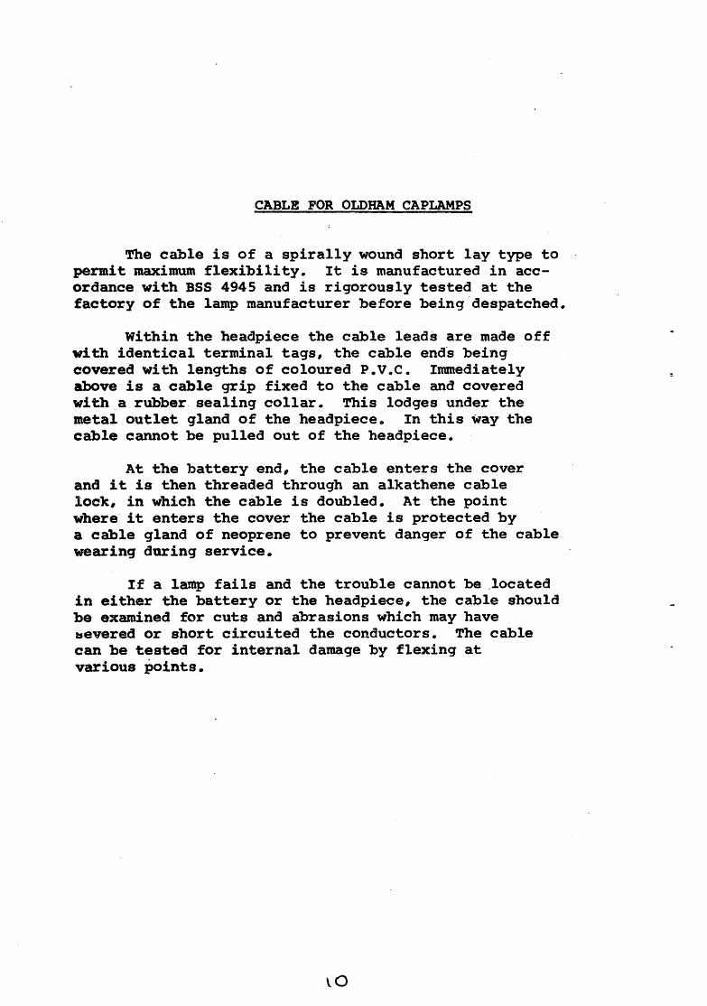
Before attempting to undertake any repair or replacement of parts on the charging frame, the charger must be switched off and all the lamps disconnected from the charging circuit.
SPARE PARTS FOR CHARGING FRAME ILLUSTRATION DESCRIPTION COOE l't9 FOR !;OQf H! FOR PACI<
METAL F!JAME WOOD FRAME i!:lAHitT): (l'EW TVPE:) (Qf..O TYPE)
CHAR§IN§ ' · l''· l'a lO. IG2. 33 INDICATOR
lo 12 34 oj NUMBER PLATe ' '''· 19
' 1/06. 19 25
~ 11E§ATIVE SWITCH G. l(i7. 31 ' · 018. 0(, 10 KE'I' ASSEMflL::i'.
@ INSULATIMG SUSH ' - ' ''· 22
:?5
@) CLEARANCE WASHER G. IGG. <'3 25
~ NE§ATIVE STOP Ci. lCi1 32 G. 016. 07 10 PLATE ASSEMBLY
D ,•
INSULATOR G. IGG.25 10
~ HVl.ON SCREW l'OR 4 ~- 16. OS. 0 50 POSITtV~ 2PRIN§ CLIP
© SHAKE PROOF 2 . 18. CG. 0 50 WASHER.
@ tjEXA§ON l'IU1' ue. 1. 1. 50
~ HY LON SCREW 4. 5. 16. OS. 0 50 FOR STOP PLATE
~SUL.ATOR FOR 'I" 29 IO (0 o) P0~1TtVE SPRIMG Cl.IP
cat§2j) POSITIVE ~PAIN!} G IOG. ~8 0 IO~. 28 10 CLIP ASSEMBl.Y.
EPz> BO, 1::10, SCREW FQR I. I. 80. 05. I. 50 HUMS ER PLATE
~ CUP HODH FOR ' '" -'s l?. 451. 04 HUMBER PLATE Af"ID ll'IOICAIOR,