Embed Size (px)
Citation preview

ISO 9001:2000ISO 13485:2003
30B
IMPLANTS •INSTRUMENT SET •
SURGICAL TECHNIQUE •
PROXIMAL HUMERAL PLATE
instruction


Edition 28A dated 11.08.2008, reviewed 12.08.2008
Important Information
Proximal locking humeral plate meets international quality standards. Implants and surgical instruments are manufactured and delivered to the user in accordance with requirements of
ISO 9001/ISO 13485;
Quality System;
Council Directive 93/42/EEC.
The instruments must be washed and sterilized before the every use.
After use the instruments should be washed immediately in order to remove any organic matter (blood, tissues). Washing may be carried out in warm water using polymeric brush and appropriate solutions (containing anti-corrosion agent) approved for use in medicine. Machined washing is recommended (in ultrasonic camber).
After washing and drying the instruments shall be placed in the case and closed with its lid. Instrument set should be stored in dry condition in temperature ranging from 5 to 30 °C and humidity not exceeding 70%.
The instrument set shall sterilized (in moist heat or dry heat up to 200 °C) in accordance with duly medical procedures. Sterilization in autoclave is recommended.
The instruments constituting the instrument set (made of stainless steel, aluminum alloys and polymers) are subjected to mechanical damages and corrosion process.
It is recommended to follow:
rules of use presented in the manual of the instrument set,
appropriate medical rules concerning washing,
sterilization and storage of medicall instruments.
NON-STERILESTERILIZE BEFORE USE
●
●
●
●
●
●


5ChM Ltd., Lewickie 3b, 16-061 Juchnowiec K., POLAND
tel. +48 85 713-13-20 ÷ 25 fax +48 85 713-13-19 e-mail: [email protected]
TABLE OF CONTENT
I. INTRODUCTION ........................................................................................................................................................ 7
II. IMPLANTS ................................................................................................................................................................ 8
III. INSTRUMENTS ...................................................................................................................................................... 10
IV. PRIMARY INDICATIONS ...................................................................................................................................... 12
IV.1. Locking screw Ø3,5 insertion in proximal part .......................................................................................... 12
IV.1.1 Insertion of protective guide ............................................................................................................ 12
IV.1.2 Screwing in the guide sleeve .......................................................................................................... 12
IV.1.3 Hole drilling ..................................................................................................................................... 12
IV.1.4 Hole depth measurement ................................................................................................................ 13
IV.1.5 Wprowadzenie wkręta ..................................................................................................................... 14
IV.2 Locking screw Ø3.5 insertion in shaft part ................................................................................................. 15
IV.2.1 Screwing in the guide sleeve .......................................................................................................... 15
IV.2.2 Hole drilling ..................................................................................................................................... 15
IV.2.3. Hole depth measurement ............................................................................................................... 16
IV.2.4 Screw insertion................................................................................................................................ 17
IV.3 Cortical screw Ø3.5 insertion in shaft part ................................................................................................. 18
IV.3.1 Compression guide setting.............................................................................................................. 18
IV.3.1a Neutral position ............................................................................................................................. 18
IV.3.1b Compression position.................................................................................................................... 18
IV.3.1c Angular position............................................................................................................................. 18
IV.3.2 Drilling ............................................................................................................................................. 19
IV.3.3 Hole depth measurement ................................................................................................................ 19
IV.3.4 Screwing the screw ......................................................................................................................... 20
V.4 Kirschner Ø1,0 wire usage.......................................................................................................................... 20
VI. SURGERY TECHNIQUE ....................................................................................................................................... 21
VI.1 Patient position ......................................................................................................................................... 21
VI.2 Surgical approach ...................................................................................................................................... 21
VI.3 Reduce the fracture ................................................................................................................................... 21
VI.4 Targeting block attachment........................................................................................................................ 22
VI.5 Plate application......................................................................................................................................... 23
VI.6 Temporary plate positioning....................................................................................................................... 24
VI.7 Screws insertion......................................................................................................................................... 25
VI.7.1 Option A .......................................................................................................................................... 26
VI.7.2 Option B .......................................................................................................................................... 28
VII. POSTOPERATIVE PROCEDURE ........................................................................................................................ 30
VIII. IMPLANT REMOVAL .......................................................................................................................................... 30


7ChM Ltd., Lewickie 3b, 16-061 Juchnowiec K., POLAND
tel. +48 85 713-13-20 ÷ 25 fax +48 85 713-13-19 e-mail: [email protected]
INTRODUCTION
I. INTRODUCTIONLocking humeral plate 3.4034 is provided for humeral bone proximal section treatment. Plate is an element of ChLP locking plates system developed by ChM company. Introduced range of implants is made of titanium and its alloys in agreement with ISO 5832 standard. ISO 9001:2000, EN ISO 13485:2003 Quality Management Systems and fulfill requirements of 93/42/EEC Directive, are high quality implants work guarantee.
Set for proximal section of humeral bone consists of:● implants (humeral plate, locking screws and standard cortical screws),● instrument set, consist of instruments used to perform the surgical procedure,● instruction for use.
IndicationsMain purpose of surgical treatment of humeral bone fractures with 3.4034 plate is anatomical structure reconstruction, also faster recovery to public and vocational life. Stabilization with this method stand out with possibility of precise reduction, angle-stable fixation of bone fragments, with preservation of blood supply.
Plate is intended for treatment of:● fractures in proximal part of humeral bone and fractures extended to femoral bone shaft,● fractures witch dislocation,● osteopenic bone fractures,● osteotomy,● malunion of the bone, non-union of bone fragments.
Contraindications● infections,● children in growth phase.
8
1, 2, 3...
E
D2D1
C2C1
B2B1
A1 A2
1, 2, 3...
A1, A2
C1, C2
D1, D2
B1
B2
E1
ChM Ltd., Lewickie 3b, 16-061 Juchnowiec K., POLANDtel. +48 85 713-13-20 ÷ 25 fax +48 85 713-13-19 e-mail: [email protected]
IMPLANTS
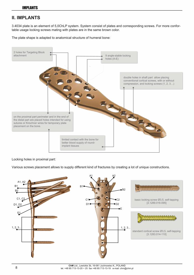
II. IMPLANTS3.4034 plate is an element of 5,0ChLP system. System consist of plates and corresponding screws. For more confor-table usage locking screws mating with plates are in the same brown color.
The plate shape is adapted to anatomical structure of humeral bone:
limited contact with the bone for better blood supply of round-implant tissues
double holes in shaft part allow placing conventional cortical screws, with or without compression, and locking screws (1, 2, 3…)
9 angle-stable locking holes (A-E)
on the proximal part perimeter and in the end of the distal part are placed holes intended for using sutures or Kirschner wires for temporary plate placement on the bone.
2 holes for Targeting Block attachment
basic locking screw Ø3,5, self-tapping [3.1289.016-095]
standard cortical screw Ø3,5, self-tapping [3.1283.014-110]
Locking holes in proximal part:
Various screws placement allows to supply different kind of fractures by creating a lot of unique constructions.

9
Ø 3,5
L
Ø 3,5
L
2,5 [mm]
Ø 3,5
L
2,5 [mm]
Ø 3,5
Ø 3,5
ChM Ltd., Lewickie 3b, 16-061 Juchnowiec K., POLANDtel. +48 85 713-13-20 ÷ 25 fax +48 85 713-13-19 e-mail: [email protected]
IMPLANTS
5,0 ChLP Humeral plate
Steel1.1289.016-095
Titanium3.1289.016-095
Steel1.1289.016-095
Titanium3.1289.016-095Steel1.1283.014-110
Titanium3.1283.014-110
O L [mm]Catalogue No.
Steel Titanium3 92 1.4034.003 3.4034.0034 105 1.4034.004 3.4034.0045 118 1.4034.005 3.4034.0056 131 1.4034.006 3.4034.006
Catalogue no.L
[mm] Steel Titanium
14 1.1283.014 3.1283.01416 1.1283.016 3.1283.01618 1.1283.018 3.1283.01820 1.1283.020 3.1283.02022 1.1283.022 3.1283.02224 1.1283.024 3.1283.02426 1.1283.026 3.1283.02628 1.1283.028 3.1283.02830 1.1283.030 3.1283.03032 1.1283.032 3.1283.03234 1.1283.034 3.1283.03436 1.1283.036 3.1283.03638 1.1283.038 3.1283.03840 1.1283.040 3.1283.04045 1.1283.045 3.1283.04550 1.1283.050 3.1283.05055 1.1283.055 3.1283.05560 1.1283.060 3.1283.06065 1.1283.065 3.1283.06570 1.1283.070 3.1283.07075 1.1283.075 3.1283.07580 1.1283.080 3.1283.08085 1.1283.085 3.1283.08590 1.1283.090 3.1283.09095 1.1283.095 3.1283.095
100 1.1283.100 3.1283.100105 1.1283.105 3.1283.105110 1.1283.110 3.1283.110
5.0 ChLP Screw Ø 3.5
Catalogue No.L
[mm] Steel Titanium
16 1.1289.016 3.1289.01618 1.1289.018 3.1289.01820 1.1289.020 3.1289.02022 1.1289.022 3.1289.02224 1.1289.024 3.1289.02426 1.1289.026 3.1289.02628 1.1289.028 3.1289.02830 1.1289.030 3.1289.03032 1.1289.032 3.1289.03234 1.1289.034 3.1289.03436 1.1289.036 3.1289.03638 1.1289.038 3.1289.03840 1.1289.040 3.1289.04042 1.1289.042 3.1289.04244 1.1289.044 3.1289.04446 1.1289.046 3.1289.04648 1.1289.048 3.1289.04850 1.1289.050 3.1289.05052 1.1289.052 3.1289.05254 1.1289.054 3.1289.05456 1.1289.056 3.1289.05658 1.1289.058 3.1289.05860 1.1289.060 3.1289.06065 1.1289.065 3.1289.06570 1.1289.070 3.1289.07075 1.1289.075 3.1289.07580 1.1289.080 3.1289.08085 1.1289.085 3.1289.08590 1.1289.090 3.1289.09095 1.1289.095 3.1289.095
Cortical Ø 3,5
self - tapping self - tapping

10ChM Ltd., Lewickie 3b, 16-061 Juchnowiec K., POLAND
tel. +48 85 713-13-20 ÷ 25 fax +48 85 713-13-19 e-mail: [email protected]
INSTRUMENTS
III. INSTRUMENTS
40.5666.010 Set for 5.0 ChLP plate - 3.4034(instruments and implants)
No. Catalogue No. Name Pcs1 40.5667.000 Instruments for 5.0 ChLP plate 12 40.5669.010 Palette for 5.0 ChLP plates - 3.4034 1
40.5667.000 Instruments for 5,0 ChLP plate
No. Catalogue No. Name Pcs1 40.5673.010 Guide sleeve 5,0/1,0 22 40.5673.018 Guide sleeve 5,0/1,8 43 40.5673.028 Guide sleeve 5,0/2,8 44 40.4804.025 Compression guide 2.5 15 40.2063.220 Drill 1.8/220 26 40.2049.220 Drill 2.5/220 27 40.5653.220 Drill with scale 2.8/220 28 40.4814.220 Kirschner wire 1.0/220 49 40.4815.220 Kirschner wire 2.0/220 4
10 40.5674.028 Setting-compressing screw 2.8/180 211 40.5675.100 Screw length measure 112 40.4639.000 Depth measure 113 40.5676.000 Screwdriver tip S2.5 114 40.5677.000 Screwdriver tip T15 115 40.5635.100 Handle 2.0Nm 116 40.4250.000 Bender for plates 4/6 217 40.5668.000 Stand for instruments for 5,0 ChLP plate 118 40.4655.000 Stand for screws Ø 3.5 119 40.4694.050 Stand for ChLP 5.0 screws 1
1. Guide sleeve 5,0/1,0 [40.5673.010]2. Guide sleeve 5,0/1,8 [40.5673.018]3. Guide sleeve 5,0/2,8 [40.5673.028]
4. Compression guide 2,5 [40.4804.025]
5. Drill 1,8/220 [40.2063.220]6. Drill 2,5/220 [40.2049.220]7. Drill with scale 2,8/220 [40.5653.220]
8. Kirschner wire 1,0/220 [40.4814.220]9. Kirschner wire 2,0/220 [40.4815.220]
10. Setting-compressing screw 2,8/180 [40.5674.028]
11. Screw length measure [40.5675.100]
12. Depth measure [40.4639.000]
13. Screwdriver tip S2,5 [40.5676]14. Screwdriver tip T15 [40.5677] 15. Handle 2,0Nm [40.5635.100]
16. Bender for plates 4/6 [40.4250.100]
17. Stand for instruments for 5,0 ChLP plate [40.5668.000]

11ChM Ltd., Lewickie 3b, 16-061 Juchnowiec K., POLAND
tel. +48 85 713-13-20 ÷ 25 fax +48 85 713-13-19 e-mail: [email protected]
INSTRUMENTS
40.5669.010Palette for 5,0ChLP plates - 3.4034(with additional instruments)Compatible with: 40.5667.000 - Instruments for 5,0ChLP plate
Lp. Catalogue No. Name Pcs
1 40.5671.000 Targeting block 12 40.5672.000 Protective guide 7,0/5,0 23 40.5669.210 Palette 1
2. Protective guide 7,0/5,0 [40.5672.000]
1. Targeting block [40.5671.000]
18. [40.4655.000] Stand for screws Ø 3.519. [40.4694.050] Stand for ChLP 5.0 screws
12
40.5672.070
40.5671.000
40.5673.028
40.5653.000
ChM Ltd., Lewickie 3b, 16-061 Juchnowiec K., POLANDtel. +48 85 713-13-20 ÷ 25 fax +48 85 713-13-19 e-mail: [email protected]
SURGICAL TECHNIQUE
The above description is not detailed instruction of conduct.The surgeon decides about choosing the operating procedure.
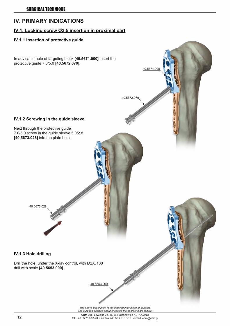
IV. PRIMARY INDICATIONSIV.1. Locking screw Ø3,5 insertion in proximal part
IV.1.1 Insertion of protective guide
In advisable hole of targeting block [40.5671.000] insert the protective guide 7,0/5,0 [40.5672.070].
IV.1.2 Screwing in the guide sleeve
Next through the protective guide 7.0/5.0 screw in the guide sleeve 5.0/2.8 [40.5673.028] into the plate hole.
IV.1.3 Hole drilling
Drill the hole, under the X-ray control, with Ø2,8/180 drill with scale [40.5653.000].

13
40.5653.000
40.5675.000
ChM Ltd., Lewickie 3b, 16-061 Juchnowiec K., POLANDtel. +48 85 713-13-20 ÷ 25 fax +48 85 713-13-19 e-mail: [email protected]
SURGICAL TECHNIQUE
The above description is not detailed instruction of conduct.The surgeon decides about choosing the operating procedure.
IV.1.4 Hole depth measurement
OPTION I:from scale on the drill [40.5653.000]
OPTION II:using screw length measure [40.5675.000].

14
40.5673.028
40.0321.000
3.1289.016÷095
ChM Ltd., Lewickie 3b, 16-061 Juchnowiec K., POLANDtel. +48 85 713-13-20 ÷ 25 fax +48 85 713-13-19 e-mail: [email protected]
SURGICAL TECHNIQUE
The above description is not detailed instruction of conduct.The surgeon decides about choosing the operating procedure.
IV.1.5 Wprowadzenie wkręta
Remove guide sleeve 5.0/2.8 [40.5673.028].
Through protective guide 7,0/5,0 [40.5672.070] insert locking screw [3.1289.016-095] using hexagonal screwdri-ver S2,5 [40.0321.000].
15
40.5673.028
40.5653.000
ChM Ltd., Lewickie 3b, 16-061 Juchnowiec K., POLANDtel. +48 85 713-13-20 ÷ 25 fax +48 85 713-13-19 e-mail: [email protected]
SURGICAL TECHNIQUE
The above description is not detailed instruction of conduct.The surgeon decides about choosing the operating procedure.
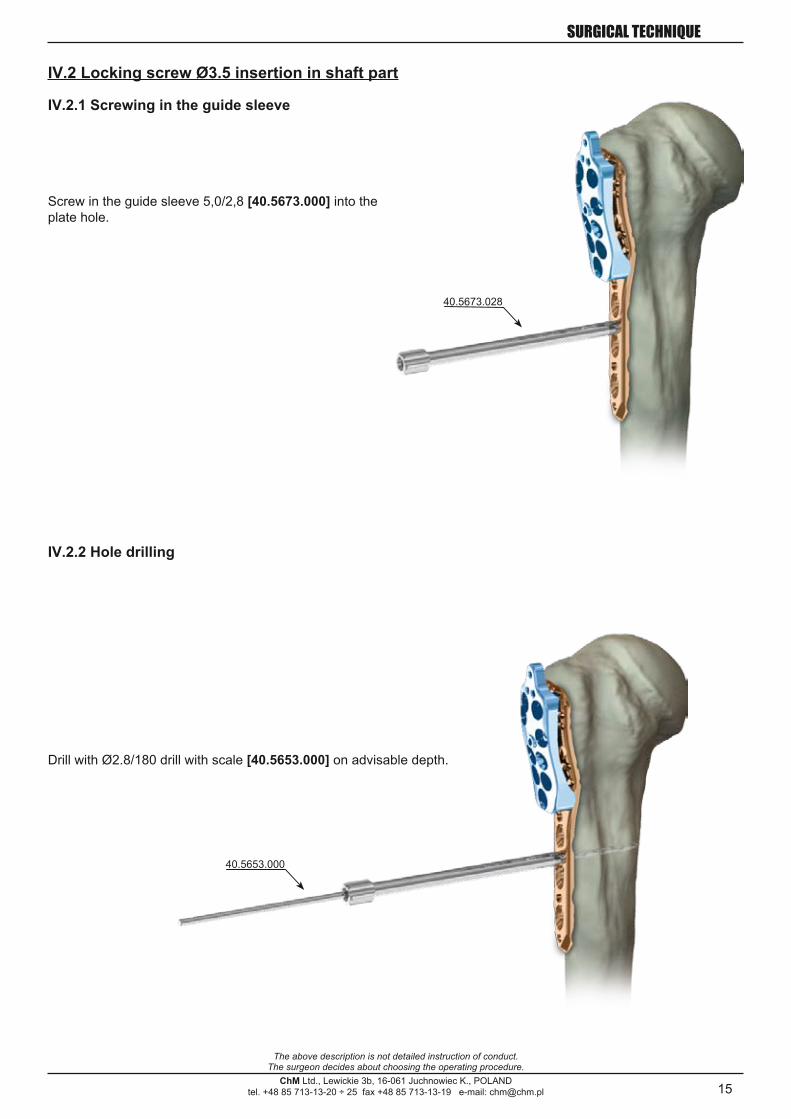
IV.2 Locking screw Ø3.5 insertion in shaft part
IV.2.1 Screwing in the guide sleeve
Screw in the guide sleeve 5,0/2,8 [40.5673.000] into the plate hole.
IV.2.2 Hole drilling
Drill with Ø2.8/180 drill with scale [40.5653.000] on advisable depth.

16
40.5653.000
40.5675.000
40.4639.000
ChM Ltd., Lewickie 3b, 16-061 Juchnowiec K., POLANDtel. +48 85 713-13-20 ÷ 25 fax +48 85 713-13-19 e-mail: [email protected]
SURGICAL TECHNIQUE
The above description is not detailed instruction of conduct.The surgeon decides about choosing the operating procedure.
IV.2.3. Hole depth measurement
OPTION I: Read value from scale on drill [40.5653.000].
OPTION II: or using screw length measure [40.5675.000].
OPTION III: After guide sleeve 5,0/2,8 [40.5673.028] unscrewing, define the screw length using the depth measure [40.4639.000].
17
40.0321.000
3.1289.016-095
ChM Ltd., Lewickie 3b, 16-061 Juchnowiec K., POLANDtel. +48 85 713-13-20 ÷ 25 fax +48 85 713-13-19 e-mail: [email protected]
SURGICAL TECHNIQUE
The above description is not detailed instruction of conduct.The surgeon decides about choosing the operating procedure.
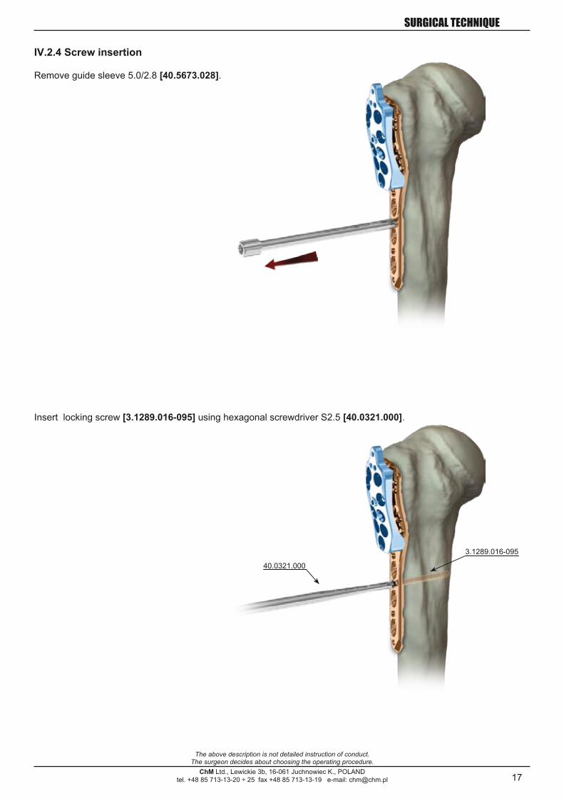
IV.2.4 Screw insertion
Remove guide sleeve 5.0/2.8 [40.5673.028].
Insert locking screw [3.1289.016-095] using hexagonal screwdriver S2.5 [40.0321.000].

18
40.4804.025
40.4804.025
40.4804.025
ChM Ltd., Lewickie 3b, 16-061 Juchnowiec K., POLANDtel. +48 85 713-13-20 ÷ 25 fax +48 85 713-13-19 e-mail: [email protected]
SURGICAL TECHNIQUE
The above description is not detailed instruction of conduct.The surgeon decides about choosing the operating procedure.
IV.3 Cortical screw Ø3.5 insertion in shaft part
IV.3.1 Compression guide setting
Set the compression guide 2,5 [40.4804.025] in advisable position:
IV.3.1a Neutral position
Press down the guide to plate. It will set in position that allow neutral insertion of the screw.
IV.3.1b Compression position
Move the guide without pressure to edge of compression hole. Hole drilled in this position allow screw insertion in compression position.
IV.3.1c Angular positionAngular positioning of the guide is also possible.
19
40.2049.180
40.4639.000
ChM Ltd., Lewickie 3b, 16-061 Juchnowiec K., POLANDtel. +48 85 713-13-20 ÷ 25 fax +48 85 713-13-19 e-mail: [email protected]
SURGICAL TECHNIQUE
The above description is not detailed instruction of conduct.The surgeon decides about choosing the operating procedure.
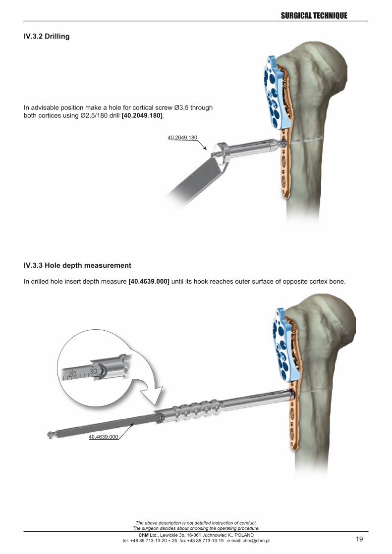
IV.3.2 Drilling
In advisable position make a hole for cortical screw Ø3,5 through both cortices using Ø2,5/180 drill [40.2049.180].
IV.3.3 Hole depth measurement
In drilled hole insert depth measure [40.4639.000] until its hook reaches outer surface of opposite cortex bone.
20
40.0321.000
3.1283.014-110
ChM Ltd., Lewickie 3b, 16-061 Juchnowiec K., POLANDtel. +48 85 713-13-20 ÷ 25 fax +48 85 713-13-19 e-mail: [email protected]
SURGICAL TECHNIQUE
The above description is not detailed instruction of conduct.The surgeon decides about choosing the operating procedure.
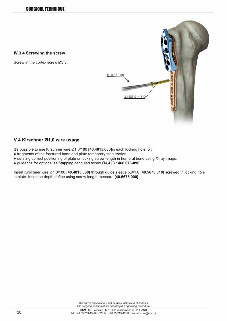
IV.3.4 Screwing the screw
Screw in the cortex screw Ø3,5.
V.4 Kirschner Ø1,0 wire usage
It’s possible to use Kirschner wire Ø1,0/180 [40.4815.000]in each locking hole for:● fragments of the fractured bone and plate temporary stabilization,● defining correct positioning of plate or locking screw length in humeral bone using X-ray image,● guidance for optional self-tapping cannuled screw Ø4,4 [3.1466.016-090].
Insert Kirschner wire Ø1,0/180 [40.4815.000] through guide sleeve 5,0/1,0 [40.5673.010] screwed in locking hole in plate. Insertion depth define using screw length measure [40.5675.000].

21ChM Ltd., Lewickie 3b, 16-061 Juchnowiec K., POLAND
tel. +48 85 713-13-20 ÷ 25 fax +48 85 713-13-19 e-mail: [email protected]
SURGICAL TECHNIQUE
The above description is not detailed instruction of conduct.The surgeon decides about choosing the operating procedure.
VI. SURGERY TECHNIQUEVI.1 Patient position
“Beach-chair” position is recommended for operation. It ensure easy approach to the shoulder.
VI.2 Surgical approach
Deltopectoral approach is recommended, between deltoid and pectoral muscles.
VI.3 Reduce the fracture
It’s necessary to perform anatomical reduction of head fragments and humeral bone tuberosity using Kirschner wires or sutures before applying humeral plate with locking screws. Head fragments and humeral bone tuberosity stabilize temporarily using Kirschner wires or additional independent screws for interfragmentary compression taking care that these don’t interfere with later applied plate and screws.Confirm correct positioning of fragments making X-ray image.Fractured bone fragments can be stabilized also with bone clamps.
Option. It’s possible to increase stability by insertion of sutures through the Ø2 holes on proximal part of the plate perimeter. If it’s planed to use sutures for fracture stabilization, it’s recommended to insert these in adequate plate holes before mounting targeting block and applying it on the bone. Fix the sutures, if necessary in tendons attachment region: supraspinatus, infraspinatus and subcapsularis. For fractures of the greater tuberosity tie plate with supraspinatus and/or infraspinatus tendon, whereas for lesser tuberosity fractures with subcapsularis.
22
40.5671.000
40.0321.000
40.5673.028
40.5672.070
ChM Ltd., Lewickie 3b, 16-061 Juchnowiec K., POLANDtel. +48 85 713-13-20 ÷ 25 fax +48 85 713-13-19 e-mail: [email protected]
SURGICAL TECHNIQUE
The above description is not detailed instruction of conduct.The surgeon decides about choosing the operating procedure.
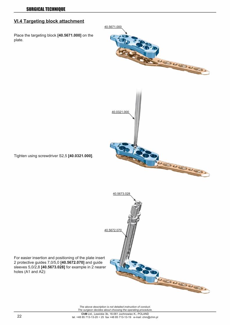
VI.4 Targeting block attachment
Place the targeting block [40.5671.000] on the plate.
Tighten using screwdriver S2,5 [40.0321.000].
For easier insertion and positioning of the plate insert 2 protective guides 7,0/5,0 [40.5672.070] and guide sleeves 5,0/2,8 [40.5673.028] for example in 2 nearer holes (A1 and A2):

23
40.4815.000
3÷5mm
8÷10mm
ChM Ltd., Lewickie 3b, 16-061 Juchnowiec K., POLANDtel. +48 85 713-13-20 ÷ 25 fax +48 85 713-13-19 e-mail: [email protected]
SURGICAL TECHNIQUE
The above description is not detailed instruction of conduct.The surgeon decides about choosing the operating procedure.
VI.5 Plate application
Place the plate on the bone and check its position in two planes:
a) anterior-posterior A/P positionUpper edge of the plate should be placed about 8÷10mm below upper edge of the greater tuberosity (rotator cuff attachment). Too high placement of the plate can increase the risk of subac-romial impingement.
To easier determination of the correct plate A/P position insert the Ø2.0 Kirschner wire [40.4815.000] through the proximal part hole of targeting block. The Kirschner wire should rest on top of the humeral head.
b) lateral positionThe plate should be centered with greater tuberosity, that is 3÷5mm from lateral bicipital groove.
24
40.4815.000
40.4815.000
40.5673.02840.5674.028
40.5674.028
ChM Ltd., Lewickie 3b, 16-061 Juchnowiec K., POLANDtel. +48 85 713-13-20 ÷ 25 fax +48 85 713-13-19 e-mail: [email protected]
SURGICAL TECHNIQUE
The above description is not detailed instruction of conduct.The surgeon decides about choosing the operating procedure.
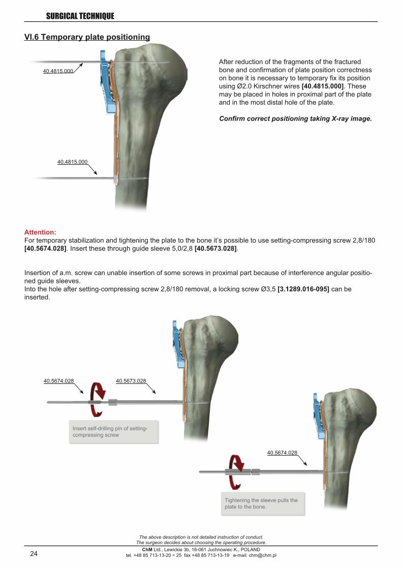
VI.6 Temporary plate positioning
After reduction of the fragments of the fractured bone and confirmation of plate position correctness on bone it is necessary to temporary fix its position using Ø2.0 Kirschner wires [40.4815.000]. These may be placed in holes in proximal part of the plate and in the most distal hole of the plate.
Confirm correct positioning taking X-ray image.
Attention:For temporary stabilization and tightening the plate to the bone it’s possible to use setting-compressing screw 2,8/180 [40.5674.028]. Insert these through guide sleeve 5,0/2,8 [40.5673.028].
Insert self-drilling pin of setting-compressing screw
Tightening the sleeve pulls the plate to the bone.
Insertion of a.m. screw can unable insertion of some screws in proximal part because of interference angular positio-ned guide sleeves.Into the hole after setting-compressing screw 2,8/180 removal, a locking screw Ø3,5 [3.1289.016-095] can be inserted.

25
5-8 mm
ChM Ltd., Lewickie 3b, 16-061 Juchnowiec K., POLANDtel. +48 85 713-13-20 ÷ 25 fax +48 85 713-13-19 e-mail: [email protected]
SURGICAL TECHNIQUE
The above description is not detailed instruction of conduct.The surgeon decides about choosing the operating procedure.
VI.7 Screws insertion
Initial screw selection depends on fracture type and obtained reduction of fracture. 2 options (option A and option B) of insertion order are described below.
In humeral bone head holes should be drilled on depth when feeling the resistance from the subchondral bone. It isn’t always possible to feel this resistance so it is recommended to use image intensification. The K-wire or drill tip should be placed as close as it is possible to the subchondral bone, i.e. about 5-8mm from the joint surface.One should avoid breaking the joint surface by reboring the opposite cortex of the humeral bone head.
It is necessary to insert at least 4-6 screws or more in the proximal part of the plate, particularly when the bone quality is low. When inserting locking screws in shaft, to obtain better fixation it’s recommended to insert these through both cortices.
26
3.1289.016-095
3.1289.016-095
ChM Ltd., Lewickie 3b, 16-061 Juchnowiec K., POLANDtel. +48 85 713-13-20 ÷ 25 fax +48 85 713-13-19 e-mail: [email protected]
SURGICAL TECHNIQUE
The above description is not detailed instruction of conduct.The surgeon decides about choosing the operating procedure.
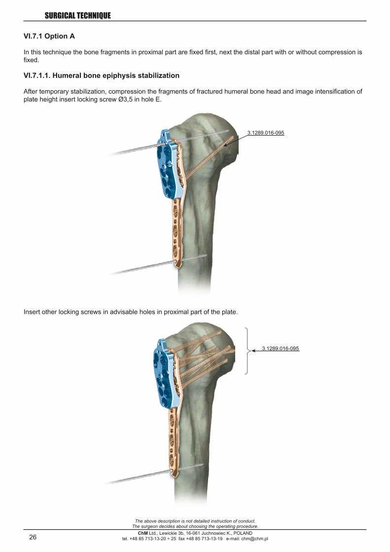
VI.7.1 Option A
In this technique the bone fragments in proximal part are fixed first, next the distal part with or without compression is fixed.
VI.7.1.1. Humeral bone epiphysis stabilization
After temporary stabilization, compression the fragments of fractured humeral bone head and image intensification of plate height insert locking screw Ø3,5 in hole E.
Insert other locking screws in advisable holes in proximal part of the plate.

27
3.1289.016-095
ChM Ltd., Lewickie 3b, 16-061 Juchnowiec K., POLANDtel. +48 85 713-13-20 ÷ 25 fax +48 85 713-13-19 e-mail: [email protected]
SURGICAL TECHNIQUE
The above description is not detailed instruction of conduct.The surgeon decides about choosing the operating procedure.
VI.7.1.2 Humeral bone shaft stabilization
Insert locking screws Ø3.5 [3.1289.016-095] in distal part of plate holes.
If it’s necessary, before insertion of locking screws in distal part, using cortical screws accomplish compression of the fragments of fractured bone.
VI.7.1.3 Targeting block [40.5671.000] removal

28
3.1283.014÷110
3.1289.016-095
ChM Ltd., Lewickie 3b, 16-061 Juchnowiec K., POLANDtel. +48 85 713-13-20 ÷ 25 fax +48 85 713-13-19 e-mail: [email protected]
SURGICAL TECHNIQUE
The above description is not detailed instruction of conduct.The surgeon decides about choosing the operating procedure.
VI.7.2 Option B
In this technique reduction of distal shaft part with plate is done first, next the final adjustment of plates height and insertion of the screws in proximal part before inserting the other screws in shaft.
VI.7.2.1 Cortical screw Ø3,5 insertion
Insert cortical screw Ø3,5 [3.1283.014÷110], in neutral position, in first or second compression hole.
VI.7.2.2 Humeral bone epiphysis stabilization
In advisable holes insert locking screws Ø3.5 [3.1289.016÷95] in humeral bone head.

29ChM Ltd., Lewickie 3b, 16-061 Juchnowiec K., POLAND
tel. +48 85 713-13-20 ÷ 25 fax +48 85 713-13-19 e-mail: [email protected]
SURGICAL TECHNIQUE
The above description is not detailed instruction of conduct.The surgeon decides about choosing the operating procedure.
VI.7.2.3 Humeral bone shaft stabilization
Insert other locking screws Ø3,5 [3.1289.016÷095] in distal part of the plate, or accomplish eventual compression in shaft section using standard bone screws Ø3,5 [3.1283.014÷110].
Any compression should be done before insertion of the locking screws. After locking screws insertion the compres-sion is not possible without locking screws removing.
VI.7.2.4 Targeting block [40.5671.000] removal
30ChM Ltd., Lewickie 3b, 16-061 Juchnowiec K., POLAND
tel. +48 85 713-13-20 ÷ 25 fax +48 85 713-13-19 e-mail: [email protected]
SURGICAL TECHNIQUE
The above description is not detailed instruction of conduct.The surgeon decides about choosing the operating procedure.
4E Intramedullary osteosynthesis of humerus 8C Dynamic Hip (DSB)/ Condylar (DSK) stabilizer20A Radial Head Prosthesis KPS23B Intramedullary osteosynthesis of femur (reversed method) 40.366024B Intramedullary osteosynthesis of femur 40.5060.00025A Intramedullary osteosynthesis of tibia 40.5000.10028A Intramedullary osteosynthesis of femur by trochanteric nail - ChFN30B Proximal humeral plate
SALES OFFICEtel.: + 48 85 713-13-30 ÷ 38fax: + 48 85 713-13-39
ChM Ltd.Lewickie 3b16-061 Juchnowiec K.Polandtel. +48 85 713-13-20 ÷ 25fax +48 85 713-13-19e-mail: [email protected]
VII. POSTOPERATIVE PROCEDURETo prevent lateral restrtiction of movement start patient exercises as soon as possible after surgery. However it is necessary to pay heed not to load the limb with full load before complete union of fractured bone.
VIII. IMPLANT REMOVALFor implant removal, in first order it is necessary to unlock all locking screws from plate. Next completely remove screws from bone. It will allow to avoid plate rotation when last locking screw is being removed.
4E Intramedullary osteosynthesis of humerus 8C Dynamic Hip (DSB)/ Condylar (DSK) stabilizer20A Radial Head Prosthesis KPS23B Intramedullary osteosynthesis of femur (reversed method) 40.366024B Intramedullary osteosynthesis of femur 40.5060.00025A Intramedullary osteosynthesis of tibia 40.5000.10028A Intramedullary osteosynthesis of femur by trochanteric nail - ChFN30B Proximal humeral plate
SALES OFFICEtel.: + 48 85 713-13-30 ÷ 38fax: + 48 85 713-13-39
ChM Ltd.Lewickie 3b16-061 Juchnowiec K.Polandtel. +48 85 713-13-20 ÷ 25fax +48 85 713-13-19e-mail: [email protected]