Embed Size (px)
Citation preview
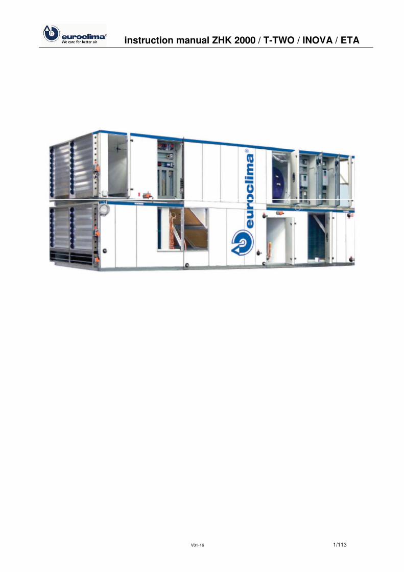
instruction manual ZHK 2000 / T-TWO / INOVA / ETA
V01-16 1/113
instruction manual ZHK 2000 / T-TWO / INOVA / ETA
V01-16 84/113
Determination of frequency converter caused problems You can determine whether problems are caused by the frequency converter by connecting the fan motor directly to mains power supply. Most commercially available frequency converters have a feature to address these problems. If the air flow is incorrect, then please contact in doubt the competent EUROCLIMA office.
9 Maintenance
EUROCLIMA units are built mostly maintenance free and easy to maintain. The maintenance inter-vals are indicative for normal operating conditions. Widely differing applications may require differ-ent intervals, ask EUROCLIMA for details.
Before servicing any electrical parts such as fan motors, damper motors, electric heater etc. use the emergency-stop control devices, to separate the parts com-pletely from the power supply. Indications of chapter 2 (Safety instructions) have to be observed!
Please understand that we cannot take care of damage caused by improper handling of solvents and cleaning agents, and no liability for mechanical damage. Solvents and cleaning agents may not contain alcohol for use on coated surfaces. In order to avoid corrosion in case of components of stainless steel like drain pans or bottom take care that parts of carbon steel laying around are removed and stainless steel parts are cleaned from swarf of carbon steel. For ordering spare parts please contact your EUROCLIMA sales partner. EUROCLIMA recommends to perform maintenance and repair work in consideration of the specifi-cations according to VDI 6022 sheet 1 chapter 5.
9.1 Control cabinet
The following maintenance work is recommended for the control cabinet of AHUs with integrated control: - annual change of the filter - annually check the function of the fan for the control cabinet ventilation (if present) - annually check the function of the heater (installed in roof units)
9.2 Fan / motor group
9.2.1 Fan
- Check for dirt, debris, damage and corrosion, clean if necessary. - Coat surface damage of the housing and impeller with zinc dust paint.

instruction manual ZHK 2000 / T-TWO / INOVA / ETA
V01-16 85/113
- Flexible connections are to be checked for damage / visual inspection. - Check vibration isolators for proper mounting / damage (visual inspection). - Check the protection grid (Fan in and/or outlet) if available for correct installation / damaged
(visual inspection). - Check the drain (if available) for function. - Test the wheel by rotating it by hand for abnormal noises. - Rotate the wheel by hand and check for strange bearing noise. - Renew both bearings if there are irregular or rough sounds. - The theoretical lifetime, depending on the operating conditions, is at least 20,000 hours. - The fan bearings are lubricated for life, only the large fan sizes with pillow block bearings annu-
ally must be lubricated with adverse operating conditions according to the following Table 9 with lithium soap grease (see Table 10). After three lubricate the bearings must be removed, cleaned and greased again.
Ambient conditions Temperature range °C Lubrication interval
Clean T < 50 6 - 12 month 50 < T < 70 2 - 4 month 70 < T < 100 2 - 6 weeks 100 < 1 week
Dusty T < 70 1 - 4 weeks 70 < T < 100 1 - 2 weeks 100 < T 1 - 7 days
Extreme humidity 1 week
Table 9: Lubrication intervals for fan bearings
Figure 129: Fan bearing with grease nipple (example Comefri NTHZ)
Supplier Type Basis Temp. range
FINA
Marson HTL 3 Lithium 30°C / +120°C
SHELL Alvania Fett 3 Lithium -20°C / + 130°C ESSO Beacon 3 Lithium -20°C / + 130°C MOBIL Mobilux EP3 Lithium -30°C / + 130°C
Table 10: Recommended grease types

instruction manual ZHK 2000 / T-TWO / INOVA / ETA
V01-16 86/113
Plug fan - The fan is directly flanged to the motor due to the absence of the belt drive it is a service friendly
component. - To reach the operating point, a frequency converter is required. - Deposits on the wheel can cause damage (risk of fatigue fracture) - impeller can burst - Danger! - Visually inspect: Check the wheel for any particular weld cracking.
9.2.2 Motor
- Check the motor for cleanliness and clean if necessary. - Measure current consumption which must not exceed the rated current indicated on the name-
plate. - Check motor bearings by rotating the shaft by hand and check with a metal rod for noise. In
case of irregular or rough sound, the corresponding bearing must be replaced. Motor bearings - Small and medium sized motors are equipped with closed bearing running for several years
without need of lubrication. - Bearings of larger motors, depending on the motor manufacturer and motor size, are equipped
with nipples for lubrication. For exact details and information regarding grease type and quan-tity for lubrication please refer to operating instructions of motor manufacturer. After three re-lubrications the bearings must be dismounted, cleaned and greased again. For lubrication in-tervals under normal operating conditions and 24 h/day load refer to Table 11.
Size 2-pole 3000 1/min
4-pole 1500 1/min
6-pole 1000 1/min
8-pole 750 1/min
bis 180 12 12 12 12 bis 250 6 12 12 12
280 3 12 12 12
Table 11: Lubrication intervals for motor bearings (in month)
- For different, unfavorable operating conditions, the intervals are to be reduced according to
motor manufacturer's instructions. - Recommended grease types for relubrication of motor bearings can be taken from Table 10
chapter 9.2.1 (Fan).
9.2.3 V-belt drive
The V-belt drive is a reliable, low-maintenance component provided that unfavorable working con-ditions as shown in Figure 130 up to Figure 133 which may reduce durability and result in reduced efficiency. The unfavorable conditions include high temperatures and inadequate filtered air and thus formation of deposits. - Check V-belt drive for dirt, damage, wear, tension and alignment (visible inspection). Belts with
damages like cracks or frayed edges must be replaced. - Pulleys must be checked for fitting, wear and damage.

instruction manual ZHK 2000 / T-TWO / INOVA / ETA
V01-16 87/113
Reasons for increased belt wear or defect - Belt contact the groove bottom / unequal set of belt / tension is too high or too low – Figure
130
Figure 130: Unfavourable operating conditions (1)
- Slippage / pulley too small / overloading / damaged disc / eccentricity, wobble – Figure 131
Figure 131: Unfavourable operating conditions (2) - Disc worn / grooved not uniform / dust, dirt / moisture, humidity – Figure 132
Figure 132: Unfavourable operating conditions (3) - Alignment / offset wheels / non-parallel plates / discs rotated to each other – Figure 133
Figure 133: Unfavourable operating conditions (4)

instruction manual ZHK 2000 / T-TWO / INOVA / ETA
V01-16 88/113
9.2.4 Re-tensioning of belts
Moving the motor away from the fan does the tensioning of the belt. Depending on the size of the motor is this:
- On a rocker swivel - On rails slidably mounted.
Loosening the lock nut and then turning the adjustment screws make the adjustment. It is im-portant to maintain the alignment of the discs accordingly – Figure 134 and Table 12. This should be checked after each tensioning with a straight edge.
Figure 134: Adjustment of pulleys
Pulley diameter dd1, dd2 in mm Max. distance x1, x2 in mm
< 112 0,5 < 224 1 < 450 2 < 630 3
Table 12: Maximum deviation at adjustment of pulleys
For quick results at the pulley alignment for factory mounted pulleys we recommend to set the same thread overhang of the threaded rods on the left and right side – Figure 135.

instruction manual ZHK 2000 / T-TWO / INOVA / ETA
V01-16 89/113
Figure 135: Adjustment of pulleys via threaded rods
In case of various pulley widths, the gap must be equal on both sides. The belt drive is to re-tension the first time after about 10 hours. Belt tension The correct tension of the belt is obtained if you have the same data as calculated (separately for each drive). The necessary information to tension new and used belt can be found on the tension-ing data sheet, which is on the inside of the fan door (Figure 136).
Figure 136: Belt transmission and tensioning data sheet
instruction manual ZHK 2000 / T-TWO / INOVA / ETA
V01-16 90/113
Following two methods for determining the tensioning are described: Force-way measurement The information - Test force FE - Indentation depth TE - Statistical belt tension (belt tension), FS The belts are to be tensioned so that the deflection TE is when the belt is loaded with the test load in point FE (such as with a spring balance). Alternatively, you can check the static belt tension FS directly with special belt tension measuring instruments. Frequency Measurement Special measuring instruments that are based on frequency measurements are available on the market. Tension the belt so, that during the measurement you measure the same frequency as in-dicated on the fan data sheet.
9.2.5 Replacing of belts
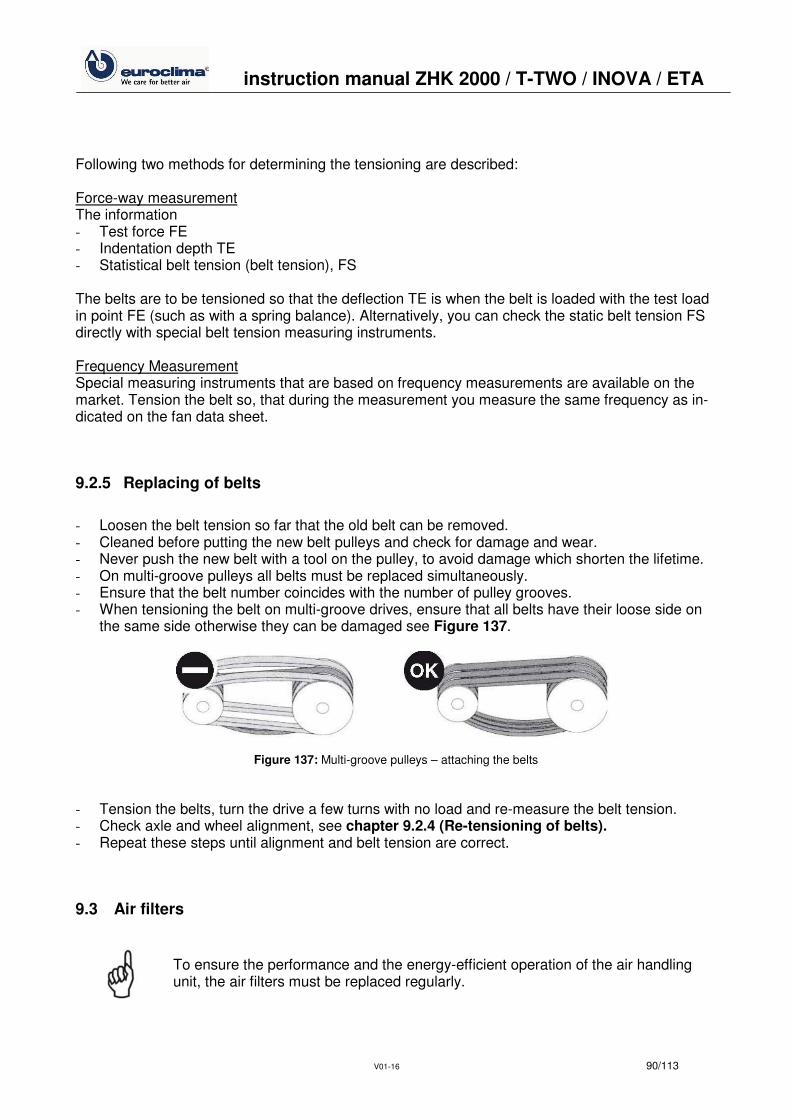
- Loosen the belt tension so far that the old belt can be removed. - Cleaned before putting the new belt pulleys and check for damage and wear. - Never push the new belt with a tool on the pulley, to avoid damage which shorten the lifetime. - On multi-groove pulleys all belts must be replaced simultaneously. - Ensure that the belt number coincides with the number of pulley grooves. - When tensioning the belt on multi-groove drives, ensure that all belts have their loose side on
the same side otherwise they can be damaged see Figure 137.
Figure 137: Multi-groove pulleys – attaching the belts
- Tension the belts, turn the drive a few turns with no load and re-measure the belt tension. - Check axle and wheel alignment, see chapter 9.2.4 (Re-tensioning of belts). - Repeat these steps until alignment and belt tension are correct.
9.3 Air filters
To ensure the performance and the energy-efficient operation of the air handling unit, the air filters must be replaced regularly.
instruction manual ZHK 2000 / T-TWO / INOVA / ETA
V01-16 91/113
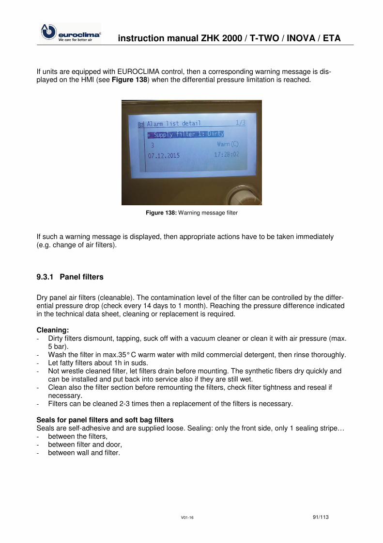
If units are equipped with EUROCLIMA control, then a corresponding warning message is dis-played on the HMI (see Figure 138) when the differential pressure limitation is reached.
Figure 138: Warning message filter
If such a warning message is displayed, then appropriate actions have to be taken immediately (e.g. change of air filters).
9.3.1 Panel filters
Dry panel air filters (cleanable). The contamination level of the filter can be controlled by the differ-ential pressure drop (check every 14 days to 1 month). Reaching the pressure difference indicated in the technical data sheet, cleaning or replacement is required. Cleaning: - Dirty filters dismount, tapping, suck off with a vacuum cleaner or clean it with air pressure (max.
5 bar). - Wash the filter in max.35° C warm water with mild commercial detergent, then rinse thoroughly. - Let fatty filters about 1h in suds. - Not wrestle cleaned filter, let filters drain before mounting. The synthetic fibers dry quickly and
can be installed and put back into service also if they are still wet. - Clean also the filter section before remounting the filters, check filter tightness and reseal if
necessary. - Filters can be cleaned 2-3 times then a replacement of the filters is necessary. Seals for panel filters and soft bag filters Seals are self-adhesive and are supplied loose. Sealing: only the front side, only 1 sealing stripe… - between the filters, - between filter and door, - between wall and filter.

instruction manual ZHK 2000 / T-TWO / INOVA / ETA
V01-16 92/113
9.3.2 Bag filters
Contamination level of the filter can be controlled by the differential pressure drop (check every 14 days to 1 month). Reaching the pressure difference indicated in the technical data sheet cleaning or replacement is required. Bag filters of class G3, G4 are repeatedly reclaimable. Clean the bags from the dust airside with a vacuum cleaner. This cleaning can be repeated several times. If this cleaning is not sufficient, also wet cleaning can be executed. Remove the bag filter, keeping the opening up, see Figure 139.
Figure 139: Transport of filter bags
Wet cleaning - Rinse the bag with upward opening with a not too strong jet of water. The mud must pass
flushed through the filter material to the outside. Possibly, add to the water a little bit detergent. - Let the clean filter bags drain well, they can be remounted wet and immediately put back into
service. - Clean also the filter section before remounting the filters, check filter tightness and reseal if
necessary. - Filters can be cleaned 2-3 times then a replacement of the filters is necessary. - Filter elements in the clamping frame must be fitted with four springs per filter. Check air tight-
ness! - Bag filter with class EU5 and above cannot be regenerated and must be renewed after the first
lifetime.
9.3.3 HEPA filters
- Contamination level of the filter can be controlled by the differential pressure drop (check every
14 days to 1 month), replace filter if necessary. - Check filter sealing and fastening. The filters clamps have to be tightened evenly. Tighten the
clamps clockwise in two stages.

instruction manual ZHK 2000 / T-TWO / INOVA / ETA
V01-16 93/113
9.3.4 Auto roll filters
- Detailed maintenance instructions are in the auto roll filter section! - These filters work automatically and can be monitored by the controlling device. A warning indi-
cates the filter strip is finished. The filter roll must be replaced. - Every six months the oil level is to check. Lubricate roller chain and gears. Use for the gears
and chain wheels oil, according to the manufacturer instructions.
9.4 Heat exchangers
- For prolonged standstill, we recommend the complete emptying of the heat exchanger. - At each refill the heat exchanger must be vented properly.
9.4.1 Medium water / steam
Heat exchangers special maintenance is not required, only occasional cleaning is recommended. Depending on the hours of operation and filter maintenance approximately every three months, the heat exchanger fins shall be check for dust contamination, debris and cleaned if necessary. The piping is to check for leaks. Cleaning Cleaning is carried out in the mounted state with a strong vacuum cleaner from the dust airside. For strongly adhering dust the heat exchanger can be dismounted and cleaned with water. Galva-nized steel coils can be cleaned with steam cleaner or by washing the fins with a strong water jet. You may take a soft brush to help, but not damage the fins.
The fins of copper-aluminium heat exchangers are particularly sensitive, there-fore, use water with low-pressure for cleaning. Damaging the fins by mechanical force leads to premature deterioration of the heat exchanger.
Corrosion spots must be cleaned and protected with zinc dust paint. Antifreeze protection Check antifreeze activity before each winter season. Check frost protection thermostat for correct setting. Drain pan Drain pan and drain should be checked for debris and cleaned, if necessary – Figure 140.
Figure 140: Cleaning of air coolers
clean here
instruction manual ZHK 2000 / T-TWO / INOVA / ETA
V01-16 94/113
Droplet eliminator Check droplet eliminator about once a year for contamination. Remove fins and clean if necessary. Contamination can cause damage by water drops and reduce the performance of the device. Please make sure that the fins are installed properly and are not bent.
Pollutants can cause poor performance of the AHU as well as damage due to drop flight.
Steam Coil Check automatic vapor supply stop and automatic fan run for some minutes, when after unit shut down.
9.4.2 Refrigerant
For the medium refrigerant (direct evaporator or condenser coil) the same actions apply as de-scribed in chapter 9.4.1(Medium water / steam). Additional actions to be taken see chapter 9.10 (Refrigeration circuit).
9.4.3 Electric Heater
- When working on the electric heater, refer to instructions in chapter 2 (Safety instructions). - Check electric heaters for dirt and corrosion, clean heating elements if necessary. - Check built-in safety devices and electrical parts for proper functioning.
9.5 Humidifier, Air washers
9.5.1 Pump
The maintenance of pumps and motors is done according to the manufacturer's instructions. In general: - Regular cleaning of all components largely determines the hygiene of the entire system. - Never let operate the pump without liquid. - Protect the pump from any solids. - When unused for long periods the water must be released for hygiene reasons and the drain
must be cleaned properly. Drain the pump as well. - The need for a sterilizing system depends on the operating conditions and is to check case by
case.

instruction manual ZHK 2000 / T-TWO / INOVA / ETA
V01-16 95/113
9.5.2 Air washers
In general: - Check water supply for properly function and check the water level, adjust if necessary. - Fill tank and siphon with clean water and adjust the float valve so that the valve closes at a wa-
ter level of 2-3 cm below the overflow. - Depending on water pollution, hardness and processing the air washer are to rid of deposits
and impurities: Severe calcification of components such as nozzles and droplet eliminators in-dicate an insufficiently effective water treatment. Calcification of nozzles and droplet eliminators can be removed by treatment with dilute formic acid. After treatment rinse well with clean wa-ter.
- Replace corroded or damaged droplet eliminator fins. - Check sieves for dirt deposits and clean if necessary. - Disassemble and clean the nozzles. - Check water tank overflow, and U-trap for debris and clean if necessary. - Damage nozzles are to be replaced. Never clean the nozzle holes with hard objects. Clean
drain valve with, high-pressure water. - Check the bleed of valve settings and proper function. - Check pump piping for leaks. - Check hoses for cracks, replace if necessary. - Check that hose clamps are tight.
9.5.3 Steam humidifiers
Maintenance according to the instruction of the manufacturer. The following informations are general rules: - Check water sieves for contamination and clean if necessary. - Check operation of solenoid valves, and clean if necessary. - Check steam distribution for deposits. - Check steam supply for leaks. - Check function of the condensate drain. - Check electrical contacts on the pump for corrosion. - Measure the current consumption. - Clean entire piping system, control and safety devices. - Check proper function of control and security devices. - Measure the humidifier performance after maintenance.
9.5.4 Honey comb humidifiers
Please refer to the indications for air washers in chapter 9.5.2 (Air washers). In general: - The float valve has to close securely at a water level of 2-3 cm below the overflow to ensure
bubble free suction. Possible readjustments have to be performed in the course of any regular inspections.
- Heavily calcified honeycomb packets must be renewed.

instruction manual ZHK 2000 / T-TWO / INOVA / ETA
V01-16 96/113
- In mild calcification the parked can be cleaned by adding decalcifier to the circulating water (shut down the unit before adding decalcifier). After that clean the section and tubes properly with fresh water.
9.5.5 Spray tube humidifiers
Please refer to the indications for air washers in chapter 9.5.2 (Air washers). In general: - Remove tubes and nozzle for cleaning. - Clean drain pan and drain.
9.6 Dampers
EUROCLIMA dampers of type J are nearly maintenance free. Check for dirt, damage and corro-sion, clean if necessary with compressed air or steam jet. Check the function and correct rotation. Spray the wheels with silicone spray if necessary. Warning! Gears cannot be treated with organic oils! Check linkages, tighten the screws if necessary.
9.7 Sound attenuators
The Silencers are basically maintenance free. In the context of larger maintenance they can be checked for dust and cleaned with a vacuum cleaner.
9.8 Weather louver
Check for dirt, damage and corrosion, free from leaves, paper, etc.
9.9 Energy recovery systems
9.9.1 Plate heat exchangers
Plate heat exchangers are made of highly corrosion-resistant high-grade aluminum and have no drive or moving parts. The lifetime is nearly unlimited, as long as the differential pressure between the plates does not exceed the max. allowed. The only maintenance required is cleaning: - Clean the condensate drain, control and fill the U-trap. The plate pack is normally self-cleaning.

instruction manual ZHK 2000 / T-TWO / INOVA / ETA
V01-16 97/113
o Removed fibers and dust at the exchanger inlet with a brush. o Clean oils and fats with hot water, household cleaners or degreasing steam.
- Check for proper operation of differential pressure switch – for function refer to chapter 7.6 (Differential pressure restriction for plate heat exchangers).
- If there is a bypass damper, please refer to chapter 9.6 (Dampers).
9.9.2 Heat wheels
Check the drive unit according to manufacturer's instructions. In general: - The construction of the storage mass is nearly complete self-cleaning. - The rotor can be cleaned with compressed air, water, steam and grease-dissolving household
cleaning products. - The sliding seal, which seals the rotor, is to check and adjust if necessary.
9.9.3 Heat pipes
Heat pipe components have no drive or moving parts, maintenance is limited to cleaning: - Clean the drain pan and check the siphon. Fill the siphon if necessary. - Fins cleaned by:
o Compressed air against the air flow direction or o Spraying with low pressure water, if required add household cleaning detergent.
- If bypass dampers exists, please refer to chapter 9.6 (Dampers).
9.9.4 Accublocs
Electrical connection: The accubloc is supplied including controller supplied loose (configured with default values), in-cluding operating instruction. On site must be provided: - Power supply 3x400V (efficiency according to technical data sheet) - Control signal 0-10V All bearings are self-lubricating ball bearings or bronze bearings. This should not be lubricated. It is important to ensure that the sensor is about 2 mm away from the engine. This can be checked with a 2mm thick piece of sheet metal. If necessary, the distance can be readjusted. The inner side of the sensor is accessible through the open damper with a wrench SW17.
Caution! Switch off before installation and secure against accidental reconnec-tion.

instruction manual ZHK 2000 / T-TWO / INOVA / ETA
V01-16 98/113
Figure 141: Scheme of an accubloc
Figure 142: Position of the sensor
The only maintenance required is periodic cleaning of the memory blocs. The cleaning intervals can define by visual inspection. The memory blocs are to take off as follows for cleaning: 1. Switch the safety switch to OFF, it must be ensured that the accubloc - control is off. 2. Dismount the unit wall on the access side. 3. Dismount the cover sheet for the damper linkage. 4. Dismount the damper linkage. 5. Unscrew the metal cover. 6. On site an adapted devise must be mounted on the accubloc frame, which allows the extrac-
tion of the memory blocs. The devise should contain a guide and an end stop, similar to the in-ternal management. Be careful! The memory blocs run very easily.
7. The second memory bloc is reachable when the wall between the memory blocs is pulled out. Therefore are two handle holes on the upper half.
8. The memory blocs should be cleaned with water with less than 20 bar and with a distance of about 20cm from the surface of the memory bloc. If chemical cleaning additives were used they should be suitable for aluminum (alkali-free).
9.10 Refrigeration circuit
To ensure the environmental requirements, the operational reliability and a long lifetime of refriger-ation circuit periodic leakage and maintenance checks are required.
9.10.1 Leakage checks
- have to be performed according to EU-regulations indicated in Records for refrigeration circuit
application in air-conditioning units supplied by EUROCLIMA. Execution by certified refrigera-tion technician at intervals that depend on the refrigerant filling quantity.
- have to be documented in Records for refrigeration circuit application in air-conditioning units.

instruction manual ZHK 2000 / T-TWO / INOVA / ETA
V01-16 99/113
The type of refrigerant and the refrigerant charge is attached on a sticker applied next to compressor. Refrigerant contains fluorinated hydrocarbons indicated in the Kyoto Protocol with the following global warming potential (GWP = Global Warming Potential), based on CO2 (data from EN378 part 1): - R407C: GWP = 1650 - R410A: GWP = 1980 - R134A: GWP = 1300
9.10.2 Maintenance
- has to be performed only by qualified personal and at least once a year. - has to be documented in supplied Records for refrigeration circuit application in air-conditioning
units. Whole system: - Check pressures and temperatures of the system. - Pay attention to unusual operating noises and to possible vibrations. Compressor: - Check oil sight glass in the crankcase (if present); in the on mode must be visible oil in the sight
glass; otherwise must be checked if there has been loss of oil (even outside of the unit is possi-ble); and optionally fill in oil directly by an oil pump directly into the compressor suction side. Only use oil that is approved by compressor manufacturer.
- Out of compressor operation compressor crankcase heater switches on in order to avoid an accumulation of refrigerant in the oil. Too much refrigerant in the oil causes a dilution of the oil resulting in a loss of viscosity leading to reduced lubrication of all moving parts. To start the compressor manually, it has to be proceeded as described in chapter 8.2.2 (Manually starting the compressor via EUROCLIMA control system).
- Follow maintenance and inspection requirements of compressor manufacturer. These instruc-tions are supplied from EUROCLIMA or can be ordered from EUROCLIMA.
Filter drier: Each refrigeration circuit is equipped with a filter drier. If refrigeration circuit has to be repaired filter drier must be replaced. Sight glass in liquid line and on receiver Liquid line sight glass contains a moisture indicator for refrigerant operating as follows: Indicator green = dry Indicator yellow = wet If indicator shows wet refrigerant, at least the filter drier must be changed, further measures may be necessary. The correct quantity of refrigerant can be checked at operating refrigeration circuit. In both sight glasses (note: sight glass on receiver according to circuit execution not always supplied) refrigerant must be visible. The sight glass in liquid line must be filled completely. Expansion valve: - Check superheating of expansion valve which should amount to 5 to 10K. Check that the tem-
perature sensor is correctly fitted as well as the pressure compensation pipe.

instruction manual ZHK 2000 / T-TWO / INOVA / ETA
V01-16 100/113
- With an electronic expansion valve the corresponding values must be followed by control unit. Instructions from valve manufacturer are supplied by EUROCLIMA.
High pressure safety switch: The high pressure switch stops the compressor when the allowed equipment pressure is exceeded. A functional check must be carried out during commissioning and must be performed at each mainte-nance work. Low pressure safety switch: The low pressure switch stops the compressor when the equipment pressure decreases the allowed low pressure. A functional check must be carried out during commissioning and must be performed at each maintenance work. Handling: If the unit goes into high or low pressure the problem must be acknowledged at the control panel for the compressors to start again. Electrical superheat controller The electronic superheat controller has an internal battery, so that the valve closes securely even during power failures. Without this feature the valve remains open, resulting in liquid hammering in the compressor at the restart. Liquid hammering can cause damage of the compressor.
Therefore, the annual replacement of the battery is recommended for safety rea-sons.
9.10.3 Inspection
Inspection work may be carried out by the operator in trimestrial intervals. All equipment: - Have a look for loosen links, fasteners etc., tighten if necessary. - Pay attention to unusual noise. - Have a look for oil leakage on components and joints. Air-cooled condenser, direct expansion evaporator: Clean fin surface if necessary. Dirty fins reduce the transmission of heat which could result in unac-ceptable condensing / evaporation temperatures. Be careful not to damage the fins. Clean with com-pressed air or vacuum cleaner. Compressor: Check oil sight glass in the crankcase (if mounted). Pay attention to unusual noise. To start the compressor manually, it has to be proceeded as described in chapter 8.2.2 (Manually starting the compressor via EUROCLIMA control). Coolant contents: Check the inspection glass in the liquid line, to see whether the inspection glass is completely full. Under full load, if bubbles appear in the inspection window, the contents are not in order and must be rectified by a specialist. The appearance of bubbles under partial load can occur under certain performance windows and is not a sign of a prevailing fault with the refrigerant.

instruction manual ZHK 2000 / T-TWO / INOVA / ETA
V01-16 101/113
Condensate tray and outlet: - Examine condensate outlet and tray for dirt and clean if necessary. - Clean or rinse out condensate outlet from time to time.
9.11 Hygienic units
The maintenance plan for EUROCLIMA AHU’s you will find in the general part of instruction man-ual. EUROCLIMA recommends maintenance in dependence on: - VDMA 24186 part 1 and - VDI6022 part 1. In chapter 5 of VDI 6022 part 1, you can find detailed requests on operation
and maintenance. EUROCLIMA recommends as cleaning agent Allrain or Multirain, as disinfectant Sanosil or Sanirain of Hygan.
9.12 Maintenance plan
The maintenance intervals specified in Table 13 are based on empirical values for normal operat-ing conditions. They are designed for continuous operation (24 hours / day) in moderate temperate climates and low dust areas, such as in offices or shopping malls. Widely differing operating condi-tions, particularly with respect to air temperature, humidity and dust can significantly shorten the intervals.

instruction manual ZHK 2000 / T-TWO / INOVA / ETA
V01-16 102/113
Ch = Check, C = Clean, M = Maintenance
Component Action Section monthly
¼ year ½ year year Reference chapter
Fan / motor Ch Corrosion check X 9.2.1 Fan
Ch Flexible connection X
Ch Vibration isolators X
Ch Protection grid X
Ch Water drain X
Ch / Cl / M Fan bearings X
Ch / Cl / M Fan bearings with lubricat-ing nipples
according to Table 9 (Lubrication intervals for fan bearings)
Ch / Cl / M Motor, general X 9.2.2 Motor
Ch / M Motor bearings X
Ch / Cl / M Motor bearings with lubri-cating nipples
according to Table 11 (Lubrication inter-vals for motor bearings (in month))
Ch Check current consumption X
Ch / Cl / M Belt drive, general X 9.2.3 V-belt drive
Ch / M Belt tension first time after operation of 10 hours
X
M Belt change if necessary / at least after 2 years
Filter Ch / Cl / M Panel filters X 9.3.1 Panel filters
Ch / Cl / M Bag filters X 9.3.2 Bag filters
Cl / M HEPA filters X 9.3.3 HEPA filters
Heat exchanger Ch / Cl Fins X 9.4 Heat exchangers
Ch Frost protection X
Ch / Cl Drain pan X
Ch / Cl Droplet eliminator X
Ch Steam coil X
Electric heater Ch / Cl E-heater X 9.4.3 Electric Heater
Check e-heater section for thermal damages after every mains supply failure!
Humidifier Ch / M Pump X 9.5.1 Pump
Ch Air washer X 9.5.2 Air washers
Ch / Cl Decalcify / cleaning if necessary
Ch Nozzles X 9.5.5 Spray tube humidifiers
Ch Drain pan X
Ch Bleed off settings / valves X
Ch / Cl / M Steam humidifier X 9.5.3 Steam humidifiers
Ch / Cl / M Honey comb humidifier X 9.5.4 Honey comb humidifi-ers
Ch / Cl / M Spray tube humidifier X 9.5.5 Spray tube humidifiers
Dampers Ch / Cl Dampers X 9.6 Dampers
Silencer Ch / Cl Silencer X
Weather louver Ch / Cl Weather louver, grid and hood X
Energy recovery Ch / Cl Plate heat exchanger X 9.9.1 Plate heat exchangers
Ch / Cl Heat wheel X 9.9.2 Heat wheels
Ch / Cl Heat pipe X 9.9.3 Heat pipes
Refrigeration circuit Ch Leakage check
>=500 >=50 >=5 9.10.1 Leakage checks
Data in tons of CO2-equivalent
Ch / Cl Maintenance X 9.10.2 Maintenance
Ch Inspection X 9.10.3 Inspection
Control Cabinet M Filter X 9.1 Control cabinet
Ch Fan X
Ch Heater X
Table 13: Maintenance plan