Embed Size (px)
Citation preview

206-97090BJan. 2009
INSTRUCTION MANUAL
USER SYSTEM GUIDE
IRAffinity-1
SHIMADZU FOURIER TRANSFORM
INFRARED SPECTROPHOTOMETER
Read the instruction manual thoroughly before you use the product.Keep this instruction manual for future reference.

This page is intentionally left blank.

iIRAffinity-1
IMPORTANT• Do not use this instrument before fully understanding the contents of this manual.• If the user or usage location changes, ensure that this Instruction Manual is transferred with the product.• If this documentation or the warning labels on the instrument become lost or damaged, promptly obtain
replacements from your Shimadzu representative.• To ensure safe operation, read the Safety Instructions before using the instrument.• To ensure safe operation, contact your Shimadzu representative for product installation, adjustment, or
re-installation (after the product is moved).
COPYRIGHT AND TRADEMARK• © 2007-2009 Shimadzu Corporation. All rights reserved. This publication may not be reproduced in whole
or in part without written permission from Shimadzu Corporation. Since Shimadzu products are frequently upgraded and improved, information in this publication is subject to change without notice. Any errors or omissions which may have occurred in this publication will be corrected as soon as possible. We appreciate notification of any errors or omissions.Windows is a registered trademark of Microsoft Corporation in the United States and/or other countries. Other product names described in this manual are each manufacturer's trademarks or registered trademarks.
Read this manual thoroughly before using the instrument.
Thank you for purchasing this instrument. This manual describes: the installation, operation, cautions for use, and details on the accessories and options. Read the manual thoroughly before using the instrument. Use the instrument in accordance with the manual's instructions.Keep this manual for future reference.
Introduction

ii IRAffinity-1
The documentation for the IRAffinity-1 infrared spectrophotometer is comprised of three volumes:Operation Guide Describes basic operation using examples.User System Guide Describes installation and maintenance procedures.Validation program Describes operations of the validation programs for use with the FTIR.
An electrical file (pdf) of the Validation program manual is stored in the IRsolution Installation CD.
The IRAffinity-1 Instruction Manual: User System Guide primarily describes the IRAffinity-1 hardware, including its unit description, installation and maintenance. Refer to the Instruction Manual: Operation Guide for operation procedures such as data acquisition and processing, and to the "Help" document which is included in IRsolution software itself for a detailed description of each command. For information about your PC and printer, refer to their individual product manuals.
This instruction manual consists of
Safety Precautions Describes precautions. Read this section before using your FTIR.
Chapter 1Principles, Description, and Functions of the IRAffinity-1
Describes FTIR principles, Description or Functions.
Chapter 2Specifications
Describes specifications.
Chapter 3Installation
Describes specification of installation site and software installation.
Chapter 4Operations
Describes outlines of operation of the IRAffinity-1. Refer to the Operation Guide and Help file in detail.
Chapter 5Maintenance and Inspection
Describes procedures of FTIR maintenance.
Chapter 6Troubleshooting
Describes troubleshooting.
Chapter 7Materials for Infrared Analysis
Describes materials used for Infrared analysis and IRaffinity-1. Material Safety Data Sheets are on this section.
Index
Use of Instruction Manuals

iiiIRAffinity-1
• To ensure safe operation of the instrument, read these Safety Instructions carefully before use.• Observe all of the WARNINGS and CAUTIONS described in this section. They are extremely important for
safety.• In this manual, warnings and cautions are indicated using the following conventions;
Application Precautions
Installation Site Precautions
DANGER Indicates an imminently hazardous situation which, if not avoided, will result in serious injury or death.
WARNING Indicates a potentially hazardous situation which, if not avoided, could result in serious injury or possibly death.
CAUTION Indicates a potentially hazardous situation which, if not avoided, may result in minor to moderate injury or equipment damage.
NOTE Emphasizes additional information that is provided to ensure the proper use of this product.
WARNING
This instrument is an infrared spectrophotometer.Use this instrument ONLY for the intended purpose.Using this instrument for any other purpose could cause accidents.
WARNING
• This product is not an explosion-proof product.It ignites and causes a fire.Since this instrument includes electrically active parts even if the power switch is off, it ignites and causes a fire if there are any flammable gases in explosive (flammable) range around this instrument. Do not leave the material that generates the flammable gas around this instrument.
• Some of solvents used for FTIR applications are flammable and toxic. The room where the instrument is installed should be well ventilated; otherwise, solvent vapors could cause poisoning or ignite and cause a fire.
• When organic solvents are used for FTIR applications, use of open flame in the vicinity of this instrument must be strictly prohibited. Do not install the instrument in the same room with any other equipment that emits or could potentially emit sparks, since sparks could cause a fire.Provide fire extinguishers for use in case of fire.
• When organic solvents are used for FTIR applications, provide protective equipment near the instrument.If solvent gets into the eyes or on the skin, it must be flushed away immediately. Provide equipment, such as eye wash stations and safety showers, as close to the instrument as possible.
Safety Instructions

iv IRAffinity-1
Installation Precautions
CAUTION
• During installation, consider the entire weight of all of this system including this instrument and accessories.The lab table on which this instrument is installed should be strong enough to support the total weight of the system. It should be level and stable.Otherwise, the instrument could tip over or fall off the table.
• Avoid installation sites that are exposed to corrosive gases, vapors of organic halides, organic solvents, Siloxane, oil mists or excessive dust.These adverse conditions may be detrimental to maintaining the instrument performance and may shorten its service life.
• Additional information for applications using organic halidesIf vapors of any organic halide, such as difluoromethane (CH2F2), dichloromethane (CH2Cl2), chloroform (CHCl3), or carbon tetrachloride (CCl4) enter the interferometer, they are decomposed by the heat of the light source to highly caustic hydrogen halides such as Hydrofluoric acid (HF), Hydrochloric acid (HCl), etc. Mirrors, other optical elements, screws and another parts in the interferometer might be damaged. Please prevent the entry of organic halide vapors into the interferometer by installing a local ventilation system at the FTIR sample compartment, or purging the interferometer with dried air or N2 gas, when you run samples that include volatile organic halide compounds.
WARNING
• To ensure safe operation, contact your Shimadzu representative if product installation, adjustment, or re-installation (after the product is moved) is required.
• Take measures to prevent the instrument from falling in the event of an earthquake or other disaster.Strong vibrations could cause the instrument to fall over, resulting in injury.
• The power supply voltage of the instrument is indicated on the label on the back of the instrument. Connect the instrument only to a power supply of the voltage indicated; otherwise, fire or electric shock could result. Check that the power supply voltage is stable and that its current capacity is sufficient to operate all the components of the system. If not, the instrument will not operate at its rated performance.
• Ground the instrument.Grounding is necessary to prevent electric shock in the event of an accident or electrical discharge, and important for ensuring stable operation.
• Do not place heavy objects on the power cord, and keep any hot items away.The cord could be damaged, resulting in fire, electrical shock or malfunction. If the cord becomes damaged, contact your Shimadzu representative immediately.
• Do not modify the cord in any way. Do not bend it excessively or pull on it.The cord could be damaged, resulting in fire, electrical shock or malfunction. If the cord becomes damaged, contact your Shimadzu representative immediately.
• Please insert the power cord in the power outlet at an easily accessible position.The power cord must be unplugged from the power outlet in case of emergency.

vIRAffinity-1
Operation Precautions
CAUTION
• When installing the instrument, be careful not to pinch your fingers between the system components, as this could result in injury.
• When opening the doors, be careful not to pinch your fingers as this could result in injury.
WARNING
• Take thorough measures to prevent buildup of static electricity.Static electricity could result in fire or explosion.
• Always wear protective gloves and protective goggles when handling solvents and samples.If solvent gets into the eyes, blindness could result.Should solvent get into the eyes, flush immediately with large amounts of water and get medical attention.
• Always wear protective gloves when handling any toxic or biologically infectious samples.
• Do not use flammable sprays (hair sprays, insecticide sprays, etc.) near the instrument.They could ignite and cause a fire.
CAUTION
• Wipe the FTIR and/or inside of its sample compartment immediately, when they are wet by any liquid samples such as water, organic solvents, etc.The instrument could be damaged.

vi IRAffinity-1
Measures for Preventing Static Electricity Accidents
WARNING
• Take thorough measures to prevent buildup of static electricity.Static electricity could result in fire or explosion.
CAUTION
• The best way to prevent static electricity accidents is simply to prevent the occurrence and accumulation of electro-static charges.
• It is important to combine multiple preventive measures.• If large amounts of flammable solvents are collected in a large container, implement preventive
measures 1 to 5 below.
Preventive measure 1:Use a metal container for the waste liquid which grounds the container. This will ensure that the electrical charges of the container and liquids pass to the ground. Accessories for this measure:
• Be sure to ground the metal waste container properly. If the grounding wire is not properly attached or connected to the ground, static electricity can build up in the metal container.
• Some metal containers have surfaces that are laminated or oxidized, and therefore do not conduct electricity. After grounding the metal container, use a tester to make sure that electricity is conducted to the ground.
• If the liquid to be drained into the waste liquid container is virtually non-conductive (10−10 S/m or less), it will be necessary to add properly conductive (and therefore safe) liquid to the tank (This conductive liquid may be added beforehand).
Preventive measure 2:Cover the spaces between the tubing and the sides of the inlet and outlet openings of the waste container (with caps or the like). This will prevent any sparks generated outside the container from getting inside.
Preventive measure 3:Keep electro-statically charged objects, including the human body, away from the waste liquid container. To prevent the electro-static charging of the human body, take the following precautions:
• Wear anti-static clothing and shoes.• Ground the human body with anti-static wrist straps. (For safety, the wrist strap should be
connected to the ground using an intervening resistor of about 1 MΩ).• Spread anti-static matting or the like on the floor, to make the floor conductive.• Persons who have not taken anti-static precautions should touch some grounded metal
component before coming near the waste liquid container, in order to ground the body and clothing.
Preventive measure 4:Use tubing with an inner diameter of at least 2 mm for a drain line with high flow rates.
• Air bubbles in liquid can multiply the electro-static charge by a factor of 20, 30 or more. Periodically check the tubing connections for leaks.

viiIRAffinity-1
Preventation of Hypoxia (Oxygen Shortage)
Preventive measure 5:If it is not possible to use a conductive waste liquid container, take the following precautions:
• Ensure that the end of the inflow tube is always submerged inside the container. Also, place some type of grounded metal object (wire connected to the unit, etc.) in the liquid.
The above precautions will be ineffective for liquid of low conductivity (less than 10−10 S/m). For such liquid:
• Use as small a container as possible, to minimize damage in the event of fire.• Ambient humidity exceeding 65% will prevent static. Keep the room at a proper level of humidity.
WARNING
Maximum 10 L/min. of the purge gas is used to purge the FTIR.Take measures to prevent hypoxia in accordance with the local laws/regulations of the region in which the instrument is installed:
• Ventilate the room by opening windows or using ventilation fans during purging or after purging.• Avoid purging in a sealed room.• For safety reasons, Shimadzu recommends the use of the oxygen indicator along with the product
introduced in this manual. The following is the recommended portable oxygen indicator.
XO-2000 Oxygen IndicatorNew Cosmos Electric Co., LtdHead office 2-5-4 Mitsuya-naka, Yodogawa-ku, Osaka, 532-0036, Japane-mail [email protected] http://www.new-cosmos.co.jp/en/index.html

viii IRAffinity-1
Precautions for Instrument Inspection, Maintenance, Adjustment and Care
In an Emergency
During a Power Outage
WARNING
• Unplug the instrument before inspection, maintenance, or parts replacement.Otherwise, electrical shock or short-circuit accidents could occur.
• Never remove the main cover.This may cause injury or malfunction of the instrument or hazardous radiation exposure.The main cover does not need to be removed for routine maintenance, inspection and adjustment. Have your Shimadzu representative perform any repairs requiring removal of the main cover.
• Replace fuses only with fuses specified in this manual.Any other fuses could cause a fire.Contact your Shimadzu representative for information about fuses not described in this manual.
• If the power cord plug gets dusty, remove the plug from the power outlet and wipe away the dust with a dry cloth.If dust is allowed to accumulate, fire could result.
• Replacement parts must be of the specifications given in this manual.Use of any other parts may result in instrument damage and malfunction.
• If any water gets onto the instrument, wipe it away immediately to prevent rust. Never use alcohol or thinner solvents for cleaning the instrument.They could cause discoloration.
• Dispose of the waste liquid properly and in accordance with the instruction by your administrative department.
• Performance of procedures other than those specified herein may result in hazardous radiation exposure.
WARNING
Unplug the power cord of IRAffinity-1 instead of turning off the power switch on the front panel, if IRAffinity-1 must be completely turned off in case of rising smoke, etc.
NOTE
When AC power cannot be supplied because of the periodic inspection of utilities etc., the Dry unit does not desiccate. Replace Silica gel packages in the FTIR once a week during brownout.

ixIRAffinity-1
For safety operation, warning labels are affixed to where special attention is required.Should any of these labels peel off or be damaged, obtain replacements from Shimadzu Corporation.
WARNINGRISK OF ELECTRIC SHOCKDO NOT remove cover. Contact your Shimadzu representative for service.
WARNINGRISK OF ELECTRIC SHOCKRead instructions before changing a fuse or the inlet voltage.
Unit Warning Labels
Warning label(Part No. 037-72020-10)
Left side
Backside
Warning label(Part No. 037-72420-01)

x IRAffinity-1
NOTEWhen orange lamp is lighting, interferometer is kept in low humid. If this orange lamp is not lighting, refer to Instruction manual: User's System Guide - Troubleshooting immediately.
Notice label(Part No. 206-73588)

xiIRAffinity-1
WARNING
Compliance with Laser Requirements
The IRAffinity-1 is classified Class 1 laser product according to IEC60825-1: 1993 + A1: 1997 + A2: 2001 and the U.S. FDA 21CFR Part 1040.10/1040.11 except for deviations pursuant to Laser Notice No.50 dated June 24, 2007. And the IRAffinity-1 uses a Class 2 helium neon laser with an output of 0.5 mW, maximum in it. When the IRAffinity-1 is on, the laser is emitted continuously. It has two purposes in the system: sampling signal generation and optical axis adjustment.When the IRAffinity-1 cover is on, the sampling signal laser is not visible. However, the optical alignment laser, a weak beam with 1/5 of the laser output (0.1 mW, maximum), is continuously emitted into the work area.
Optical SpecificationWavelength: CW 632.8 nmOptical Power: 0.1 mW, maximum
Laser label (Part No.037-70839-01)

xii IRAffinity-1
Symbol Definition
Current (AC).
Symbols Found on the IRAffinity-1

xiiiIRAffinity-1
Warranty1. Validity
Please consult your Shimadzu representative for information about the extent of the warranty.
2. TermThe manufacturer will provide free replacement parts for, or repair free of charge, any instrument that fails during the warranty period, if the cause can be attributed to a defect in manufacturing.
3. Items Not Covered by the WarrantyThe warranty does not cover malfunctions that result from:
1) misuse;2) repairs or modifications made by any company other than the manufacturer or an approved company;3) external factors;4) operation under severe conditions such as environments, with high temperature, high humidity,
corrosive gas, vibration, etc.;5) in case of inevitable accidents including fire, earthquake or other forces of nature, pollution by
radioactive substances and/or harmful substances, the wars, riots, and crimes;6) moving or transporting the instrument after its initial installation;7) the consumption of items or parts that can be regarded as consumable. (For example, the service life
of an LCD display panel depends on the actual operating conditions.)8) combination uses with hardware or software other than our specification;9) damages of instrument, data and software including operation system breakdown caused by
computer viruses;10) damages of instrument, data and software including operation system breakdown caused by power
supply troubles including power blackout and instantaneous voltage decrease;11) damages of instrument, data and software including operation system breakdown caused by illegal
procedure of power on/off of devices;
After-Sales ServiceIf any problem occurs with this instrument, inspect it and take appropriate corrective action as described in this manual. If the problem persists, or symptoms not covered in this manual occur, contact your Shimadzu representative.
Replacement Parts AvailabilityReplacement parts for this instrument will be available for a period of seven (7) years after the discontinuation of the product. Thereafter, such parts may cease to be available. Note, however, that the availability of parts not manufactured by Shimadzu shall be determined by the relevant manufacturers.
Warranty and After-Sales Service

xiv IRAffinity-1
PLEASE READ THIS AGREEMENT CAREFULLY BEFORE USING THE SOFTWARE. SHIMADZU Corporation ("SMZ") is willing to license the SMZ software provided herein, together with accompanying documentation (collectively "SOFTWARE") to you only upon the condition that you accept all of the terms and condition contained in this License Agreement. By using the SOFTWARE, you agree to be bound by the terms of this Agreement. If you do not agree to all these terms of this Agreement, promptly return the unused SOFTWARE to the party (either SMZ or its reseller) from whom you acquired it to receive a refund of the amount you paid.
1. LICENSE.SMZ grants you a non-exclusive and nontransferable license to use the SOFTWARE subject to the following terms and conditions.
2. LIMITATION OF USE.Except as specifically authorized by SMZ, you may NOT:
a. Use the SOFTWARE, or permit the SOFTWARE to be used, on more than one computer at any one time.
b. Copy the SOFTWARE except one (1) archival copy of the SOFTWARE.c. Modify, reverse engineer, decompile, disassemble, or create derivative works based upon the
SOFTWARE.d. Transfer, rent, lease or grant any rights in the SOFTWARE in any form to anyone else.
3. TITLE AND OWNERSHIP.This license is not for sale and it may not be assigned or sublicensed to anyone else. Title and all associated intellectual property rights to the SOFTWARE shall remain in SMZ and/or its licensor.
4. UPGRADES.You are entitled to receive all official software upgrades for the SOFTWARE that SMZ will release as deemed necessary by SMZ. An upgrade means certain supplemental program modules and/or information for bug fixing and/or updates to the defects and/or failures of the SOFTWARE that are acknowledged or confirmed by SMZ. An upgrade excludes hardware, network, consulting services, third party products, operation and general computer system maintenance. All supplemental program module for upgrades and enhancements furnished to you shall be deemed to be part of the SOFTWARE and subject to the terms and conditions set forth in this Agreement.
5. LIMITED WARRANTY.SMZ warrants that for a period of one (1) year from the date of purchase, as evidenced by a copy of the receipt, the media on which SOFTWARE is furnished will be free of defects in materials and workmanship under normal use. Except for the foregoing, SOFTWARE is provided AS IS. Your exclusive remedy and the entire liability of SMZ and its suppliers under this limited warranty will be, at SMZ's option, repair, replacement, or refund of the Software if reported (or, upon request, returned) to the party supplying the SOFTWARE to you. In no event does SMZ warrant that the Software is error free or that you will be able to operate the SOFTWARE without problems or interruptions.EXCEPT AS SPECIFIED IN THIS WARRANTY, ALL EXPRESS OR IMPLIED CONDITIONS, REPRESENTATIONS, AND WARRANTIES INCLUDING, WITHOUT LIMITATION, ANY IMPLIED WARRANTY OF MERCHANTABILITY, FITNESS FOR A PARTICULAR PURPOSE, NONINFRINGEMENT, ARISING FROM A COURSE OF DEALING, USAGE, OR TRADE PRACTICE, ARE HEREBY EXCLUDED TO THE EXTENT ALLOWED BY APPLICABLE LAW.
Software License Agreement

xvIRAffinity-1
6. LIMITATION OF LIABILITY.IN NO EVENT WILL SMZ BE LIABLE FOR ANY LOST REVENUE, PROFIT OR DATA, OR FOR SPECIAL, INDIRECT, CONSEQUENTIAL, INCIDENTIAL OR PUNITIVE DAMAGES, HOWEVER CAUSED REGARDLESS OF THE THEORY OF LIABILITY, ARISING OUT OF OR RELATED TO THE USE OF OR INABILITY TO USE SOFTWARE, EVEN IF SMZ HAS BEEN ADVISED OF THE POSSIBILITY OF SUCH DAMAGE. IN NO EVENT WILL SMZ'S LIABILITY TO YOU, WHETHER IN CONTRACT, TORT (INCLUDING NEGRIGENCE), OR OTHERWISE, EXCEED THE AMOUNT YOU PAID FOR SOFTWARE.
7. TERMINATION.This License is effective until terminated. You may terminate this License at any time by destroying all copies of SOFTWARE including any documentation. This License will terminate immediately without notice from SMZ if you fail to comply with any provision of this License. Upon termination, you must destroy all copies of SOFTWARE.
8. GENERALa. This Agreement is the entire agreement. If any provision of this agreement is held invalid, the
remainder of this agreement shall continue in full force and effect.b. This Agreement shall be construed and governed in accordance with the laws of Japan, excluding its
conflict of law rules.c. The exclusive jurisdiction for any disputes arising out of or in connection with this Agreement shall be
Kyoto District Court of Japan.d. The invalidity or unenforceability of any provision of this Agreement shall not affect the validity or
enforceability of any other provision.

xvi IRAffinity-1
For Europe:This product complies with the requirements of EMC Directive 2004/108/EC and Low Voltage Directive 2006/95/EC.
Product Name Fourier Transform Infrared Spectrophotometer
Model Name IRAffinity-1
Manufacturer SHIMADZU CORPORATIONANALYTICAL & MEASURING INSTRUMENTS DIVISION
Address 1 NISHINOKYO-KUWABARA CHONAKAGYO-KU KYOTO 604-8511 JAPAN
Authorized Shimadzu Europa GmbHRepresentative in EU
Address Albert-Hahn-Strasse 6-10, 47269 Duisburg, F.R. Germany
Regulatory Information

xviiIRAffinity-1
To all users of Shimadzu equipment in the European Union:
Equipment marked with this symbol indicates that it was sold on or after 13th August 2005, which means it should not be disposed of with general household waste. Note that our equipment is for industrial/professional use only.
Contact Shimadzu service representative when the equipment has reached the end of its life. They will advise you regarding the equipment take-back.
With your co-operation we are aiming to reduce contamination from waste electronic and electrical equipment and preserve natural resource through re-use and recycling.Do not hesitate to ask Shimadzu service representative, if you require further information.
Action for Environment (WEEE)
WEEE Mark

xviii IRAffinity-1
Introduction
Use of Instruction Manuals
Safety Instructions
Unit Warning Labels
Symbols Found on the IRAffinity-1
Warranty and After-Sales Service
Software License Agreement
Regulatory Information
Action for Environment (WEEE)
Chapter 1 Principles, Description, and Functions of the IRAffinity-11.1 Principle and Construction ..................................................................................................... 1-21.2 Resolution and Apodization ................................................................................................... 1-51.3 The FTIR Advantage.............................................................................................................. 1-71.4 System Configuration of IRAffinity-1 ...................................................................................... 1-81.5 Interferometer ........................................................................................................................ 1-9
1.5.1 Appearance................................................................................................................ 1-91.5.2 Inside of Sample Compartment................................................................................ 1-101.5.3 Optical System ......................................................................................................... 1-111.5.4 Light Source ............................................................................................................. 1-121.5.5 Beam Splitter............................................................................................................ 1-131.5.6 Detector.................................................................................................................... 1-131.5.7 Dry Unit .................................................................................................................... 1-13
1.6 Electrical System ................................................................................................................. 1-151.7 S/N Ratio.............................................................................................................................. 1-16
Chapter 2 Specifications2.1 IRAffinity-1 Specifications ...................................................................................................... 2-2
2.1.1 Hardware (Except PC) ............................................................................................... 2-22.1.2 Software ..................................................................................................................... 2-32.1.3 Other .......................................................................................................................... 2-4
Chapter 3 Installation3.1 Inspecting Standard Accessories........................................................................................... 3-23.2 Installation Environment for Equipment ................................................................................. 3-33.3 Wiring the Cables................................................................................................................... 3-53.4 Installing the Software............................................................................................................ 3-6
3.4.1 Installation of the Driver Program for the IRAffinity-1................................................. 3-63.4.2 Installation of IRsolution ............................................................................................. 3-73.4.3 Installation of Supplemental Disk ............................................................................. 3-123.4.4 Selecting an Instrument ........................................................................................... 3-13
3.5 User Management ............................................................................................................... 3-143.6 Uninstallation of the IRsolution ............................................................................................ 3-153.7 Trial Run .............................................................................................................................. 3-16
Contents

xixIRAffinity-1
3.8 Electromagnetic Compatibility ............................................................................................. 3-17
Chapter 4 Operations4.1 Activation and Shutdown of IRAffinity-1 and PC.................................................................... 4-2
4.1.1 Activation ................................................................................................................... 4-24.1.2 Quitting....................................................................................................................... 4-2
4.2 Initialization of IRAffinity-1 and Self Diagnostics.................................................................... 4-34.3 Scan Parameters ................................................................................................................... 4-4
4.3.1 Mirror Speed, Resolution and Aperture Setting ......................................................... 4-44.4 Measurement Modes ............................................................................................................. 4-54.5 Setting for Accessory Recognition......................................................................................... 4-64.6 Auto Sampler ......................................................................................................................... 4-8
4.6.1 Installation and Setting Up ......................................................................................... 4-84.6.2 Measurement ............................................................................................................. 4-94.6.3 The Way to Move Sample Position.......................................................................... 4-10
4.7 Precautions for Using Accessories ...................................................................................... 4-114.7.1 ATR-8200HA............................................................................................................ 4-114.7.2 MIRacle A and DuraSamplIR IIA Series .................................................................. 4-114.7.3 ASC-8000T and Auto Sample Switcher ................................................................... 4-114.7.4 Accessories Which Are Mounted to the Cassette (Sample Holder)......................... 4-114.7.5 KBr Pellet, Liquid Cell, Sealed Cell, Fixed Thickness Cell....................................... 4-11
4.8 In Case of Emergency ......................................................................................................... 4-12
Chapter 5 Maintenance and Inspection5.1 Start-Up Inspection and Periodic Inspection.......................................................................... 5-2
5.1.1 Start-Up Inspection .................................................................................................... 5-25.1.1.1 Dry Indicator Check .................................................................................... 5-25.1.1.2 Silica Gel Check.......................................................................................... 5-35.1.1.3 Power Spectrum Check .............................................................................. 5-45.1.1.4 Validation Program ..................................................................................... 5-6
5.1.2 Periodic Inspection..................................................................................................... 5-65.1.2.1 Dry Indicator Check .................................................................................... 5-65.1.2.2 Silica Gel Check.......................................................................................... 5-6
5.2 When Not Using IRAffinity-1 for a Long Term (Over a Month) .............................................. 5-75.3 For Brownout ......................................................................................................................... 5-85.4 Procedure to Replace Silica Gel............................................................................................ 5-95.5 Dry Indicator ........................................................................................................................ 5-105.6 Self Diagnostics ................................................................................................................... 5-11
5.6.1 Self Diagnostics during Initialization ........................................................................ 5-115.6.2 Describing the Diagnostic Screen............................................................................ 5-125.6.3 Status Monitor .......................................................................................................... 5-14
5.7 Cleaning the System............................................................................................................ 5-165.8 Transporting the System...................................................................................................... 5-175.9 Maintenance Parts and Consumable Parts ......................................................................... 5-18
Chapter 6 Troubleshooting6.1 Error Message Table ............................................................................................................. 6-26.2 Error Message Shown in the "Status Window" ...................................................................... 6-36.3 What's Happening?................................................................................................................ 6-6
6.3.1 Abnormal Behavior during Initialization...................................................................... 6-66.3.2 The Signal Intensity of the Power Spectrum Remains Zero. ..................................... 6-66.3.3 A Part of the Mirror Is a Little White. .......................................................................... 6-7

xx IRAffinity-1
6.3.4 Power Spectrum Becomes too Small, or Fluctuates.................................................. 6-86.4 Confirming the Power Selector Switch and Fuse................................................................... 6-9
Chapter 7 Materials for Infrared Analysis7.1 Materials for Infrared Analysis ............................................................................................... 7-27.2 Characteristics of Materials.................................................................................................... 7-37.3 Optical Materials in IRAffinity-1.............................................................................................. 7-57.4 Material Safety Data Sheet .................................................................................................... 7-6
7.4.1 KRS-5......................................................................................................................... 7-67.4.1.1 Thallium Bromide (TlBr) .............................................................................. 7-67.4.1.2 Thallium Iodide (TlI) .................................................................................. 7-12
7.4.2 Potassium Bromide (KBr)......................................................................................... 7-187.4.3 Silica Gel (Desiccant)............................................................................................... 7-22
Index

1-1IRAffinity-1
Chapter 1Principles, Description, and Functions of the IRAffinity-1
CONTENTS
1.1 Principle and Construction.............................................................................................................1-21.2 Resolution and Apodization ...........................................................................................................1-51.3 The FTIR Advantage .....................................................................................................................1-71.4 System Configuration of IRAffinity-1..............................................................................................1-81.5 Interferometer ................................................................................................................................1-91.6 Electrical System .........................................................................................................................1-151.7 S/N Ratio .....................................................................................................................................1-16

Chapter 1 Principles, Description, and Functions of the IRAffinity-1
1-2 IRAffinity-1
The Fourier Transform InfraRed spectrophotometer measures an infrared spectrum by Fourier-transform of an interferogram.The Physics of Fourier Transform SpectrophotometryAn FTIR uses one of several optical systems; the IRAffinity-1 relies on a Michelson interferometer (Fig. 1.1). After passing through the aperture, light is turned into a parallel beam by the collimator mirror and enters the beam splitter. A germanium film, deposited on a potassium bromide substrate via evaporation, comprises the beam splitter; it splits the single beam into two, reflecting one to the fixed mirror and transmitting the other to the moving mirror. Both mirrors reflect their beams back to the beam splitter; part of each returning beam is reflected and transmitted. The transmitted light from the fixed mirror and the reflected light from the moving mirror recombine and interfere with each other as they travel towards the collecting mirror. The interference is either constructive or destructive.
Fig. 1.1 Michelson Interferometer
1.1 Principle and Construction
ApertureBeam splitter Light
source
Fixed mirror
Moving mirror
Detector
Collimator mirror

1.1 Principle and Construction
1-3IRAffinity-1
Assume that the light source emits monochromatic light of wavelength λ (cm). When the distance l1 between the fixed mirror and the beam splitter is equal to the distance l2 between the moving mirror and the beam splitter, the optical path difference between the two beams, χ = 2 (l1 − l2), is equal to zero, and the beams are in phase. While in phase, the beams interfere constructively with each other (Fig. 1.2 A, B). As the moving mirror is displaced λ/4 cm, the optical path difference becomes λ/2 cm, and the two beams are out of phase, interfering destructively (Fig. 1.2 A, C). Thus, the two beams interfere constructively with each other when χ = nλ and destructively when χ = (n + 1/2) λ where n is an integer.
Fig. 1.2 Interference
Equation 1.1, extrapolated from the above principles, calculates the intensity I*(χ) of light (wavelength λ) incident to the detector.
where R: energy reflected by the beam splitterT: energy transmitted by the beam splitterS (λ): radiation energy from the light source
The intensity of the light observed by the detector is a function of Equation 1.1. I(χ) denotes the light intensity, and the wavenumber σ (cm-1) replaces the wavelength λ.
The signal I(χ) observed by the detector is called an interferogram, and 4RT is labeled beam splitter efficiency.If polychromatic light is emitted instead of monochromatic light, I(χ) is given by the integration of 1.2 with respect to wavenumber.
Light from the moving mirror
Light from the fixed mirror
Light from the moving mirror
The difference of the resultant interfering light
bright
dark
λ light wave
2 λ light wave
......................................................................................................... (1.1)I* χ( ) 4RTS λ( ) 12--- 1
2--- 2πχ
1---cos+=
............................................................................................................................ (1.2)B σ( ) 2πσχcos=
I χ( ) 4RTS λ( ) 12---• 2πσχcos=
where B σ( ) 4RTS λ( ) 1 2⁄•=
.................................................................................................................... (1.3)I χ( ) B σ( ) 2πσχ σδcos0
∞
∫=

Chapter 1 Principles, Description, and Functions of the IRAffinity-1
1-4 IRAffinity-1
Equation 1.3 demonstrates that I(χ) is a Fourier cosine transform of spectrum B(σ). Thus, an inverse Fourier cosine transform of I(χ) recovers the original spectrum B(σ).
While the conventional dispersive spectrometer directly determines the intensity of B(σ) at certain wavenumbers, the FTIR detector observes the interferogram I(χ) which must be Fourier transformed to obtain the spectrum.
................................................................................................................... (1.4)B σ( ) I χ( ) 2πσχ χδcos∞–
+∞
∫=

1.2 Resolution and Apodization
1-5IRAffinity-1
Although Equation 1.4 maintains that the interferogram should be recorded from -∞ to +∞, such limits are impractical. In reality, the integration is limited to an optical path difference L, determined by the range of the moving mirror. The experimental spectrum B'(σ) differs from the theoretical spectrum B(σ) accordingly.
According to Convolution Theory,
Where F(σ) is a Fourier transform of the function A(χ) in Equation 1.6.
The measured spectrum B'(σ) is a convolution of theoretical spectrum B(σ) with F(σ). F(σ), a Fourier transform of A(χ), is called instrument function or instrumental line shape ILS.Functions A(χ) and F(σ), represented by Equations 1.6 and 1.8 respectively, are given in Fig. 1.3 (a). The function F(σ), as defined by Equation 1.8, first becomes zero at ( = ± (1/2L), where the half-width value is 0.605/L. The greater the optical path difference L, the smaller the half-value width; when the moving mirror is driven further, the resolution improves.The instrument function F(σ) involves marked submaxima, called side-lobes [Fig. 1.3 (a)]. If A(χ), as defined by 1.6, is replaced by the triangular function defined by 1.9, Equation 1.10 gives its Fourier transform.
Fig. 1.3 (b) illustrates that the instrument function defined by 1.10 has worse separation, but smaller submaxima, than that defined by 1.8. Using A(χ) to reduce the instrument function submaxima called apodization; A(χ) is called the apodization function.
Fig. 1.3 Apodization with "Rectangular" and "Triangular" Functions
1.2 Resolution and Apodization
B′ σ( ) I χ( ) 2πσχcos χdL–
L
∫=
A χ( )I χ( ) 2πσχcos χd∞–
+∞∫= ........................................................................................................... (1.5)
where A χ( ) 1 if χ( ) L≤0 if χ( ) L>
= ................................................................................................................... (1.6)
B′ σ( ) B σ( )∗F σ( )= ................................................................................................................................... (1.7)
............................................................................................................................. (1.8)
F (σ) = 2L sin (2πσL)/(2πσL)
= 2L sinχ (2σL)
............................................................................................................... (1.9)
............................................................................................... (1.10)
A(χ) =1 − | χ/L| for | χ | ≤ L0 for | χ | > L
F(σ) = Lsin2 (πσL)/(πσL)2 = Lsinχ2 (σL)
(a) "Rectangular" function (b) "Triangular" function

Chapter 1 Principles, Description, and Functions of the IRAffinity-1
1-6 IRAffinity-1
Table 1.1 lists the IRAffinity-1 apodization parameters and their characteristics.
Table 1.1 Apodization Function
Notes: (a) A (χ) = 0 (| χ | > L)(b) Ratio of the maximum submaxima peak size to the center peak size (shown in %).
The information in Table 1.1 supports using the "None" or "Box Car" ("Rectangular" Function) parameter for samples requiring high resolution, such as gas, and the "Happ" ("Happ-Genzel" Function) or "Sqr. Triaug" ("Sqr-Triaug" Function) parameter, which has fewer submaxima peaks, when high resolution is unnecessary.
Parameter Apodization Function Instrument Function Half-width value
Submaxima residue
None, Box Car
0.605/L -21%
Triang 0.88/L +4.5%
Sqr. Triang 1.18/L 0.7%
Bessel 0.952/L -4.1%
Cos 1.00/L -2.7%
Happ 0.91/L -0.6%
A χ( ) 1= 2L c 2πσL( )sin
A χ( ) 1 χL------–= L c2 πσL( )sin
A χ( ) 1 χL------–⎝ ⎠
⎛ ⎞ 2= 4L
2πσL( )2----------------------
⎩ ⎭⎨ ⎬⎧ ⎫
1 c 2πσL( )sin–
A χ( ) 1 χL---⎝ ⎠⎛ ⎞ 2
–⎩ ⎭⎨ ⎬⎧ ⎫
2
=L 2π σ×( )5 2⁄ J5 2⁄ 2π σ×( )
A χ( ) 12--- 1 π χ•
L------------⎝ ⎠⎛ ⎞cos+
⎩ ⎭⎨ ⎬⎧ ⎫
=c 2πσL( )sin
2πσ 1 4L2σ2–( )------------------------------------------
A χ( ) 0.54 0.46 πχL
------⎝ ⎠⎛ ⎞cos+= 0.54
πσ----------- 0.46( ) 4πσL2•
π2 2πσL( )2–---------------------------------------+
⎩ ⎭⎨ ⎬⎧ ⎫
2πσL( )sin

1.3 The FTIR Advantage
1-7IRAffinity-1
FTIR spectrophotometry offers at least three advantages: multiplex advantage (Fellgett advantage), aperture advantage (Throughput (Jacquinot) advantage), and wavenumber accuracy (Connes) advantage.The multiplex advantage results from the accumulation and sorting of data. In one second with one scan, the FTIR measures a spectrum of all wavenumbers. By continuing to scan for a specified period, one minute for example, and accumulating the results, a spectrum with a high S/N ratio is obtained.The aperture advantage is created by the large FTIR aperture. FTIR results depend on the aperture area and the incident angle of light. When a large aperture is used, more of the light source is available to maintain a high-throughput optical system, giving the spectrum a high S/N ratio.The wavenumber precision, or Cones, advantage is the result of the IRAffinity-1 He-Ne laser. The laser emits extremely stable monochromatic light, creating a spectrum with high wavenumber accuracy.The three FTIR advantages extend many benefits:
1. Higher sensitivity measurement2. Measures samples with low transmittance, a small sample size, or a thin layer of film on its surface.3. Higher speed measurement4. Higher wavenumber accuracy5. Highly accurate spectrum subtraction
1.3 The FTIR Advantage

Chapter 1 Principles, Description, and Functions of the IRAffinity-1
1-8 IRAffinity-1
This section briefly describes the system configuration of the IRAffinity-1.The IRAffinity-1 consists of the interferometer and a personal computer.The USB 2.0 interface is used for communication between the interferometer and the personal computer.Install the software IRsolution for controlling the FTIR to the personal computer, then operate the interferometer and execute data processing.Two types of personal computers, the desktop type and the notebook type, are available. However, when using the infrared microscope which handles image data, the notebook type is not available.
Fig. 1.4 Standard Layout Example of IRAffinity-1 System
CAUTIONThe software IRsolution for controlling the FTIR operates normally only in Windows XP Professional Service Pack 2 or later. In some personal computers, the IRsolution may not operate normally due to the effect of other software. While using the personal computer to operate the FTIR, avoid starting up any other software.
1.4 System Configuration of IRAffinity-1
PrinterPC
Keyboard
Monitor

1.5 Interferometer
1-9IRAffinity-1
1.5.1 AppearanceThis section briefly describes the appearance and the functions of the interferometer.
Fig. 1.5 Appearance (Front View and Top View) of Interferometer
(1) Power switch : Press the [ ] side to turn on the power to the laser, light source and electronic boards. Unplug the power cord of IRAffinity-1 instead of turning off the power switch, if IRAffinity-1 must be completely turned off in case of rising smoke, etc.
(2) Power indicator (green) : Lights up when the main power of the interferometer is turned on.
(3) Dry indicator (orange) : Lights up while humidity in the interferometer is low. Contact Shimadzu representative if it does not light even though the power cord is connected correctly.
(4) Sample compartment cover : Open this cover to set an optional accessory to the sample compartment or measuring a large sample, then set the accessory or the sample.
(5) Sample compartment lid : Open this lid to measure a small sample such as liquid cell or tablet, then set the sample to the sample compartment.
(6) Top cover : Open this cover to replace the Silica gels.
(7) External beam outlet cover : To install the option such as infrared microscope, remove this cover and connect it.
(8) USB connector : To connect with the personal computer
1.5 Interferometer
(3)(2) (1)
(4) (5)
(8)
(7)
(6)

Chapter 1 Principles, Description, and Functions of the IRAffinity-1
1-10 IRAffinity-1
Fig. 1.6 Appearance of Interferometer (Rear View)
(1) AC inlet (with fuse holder) : Connect the power cable here. Two fuses are accommodated here.
(2) Optional connector mounting holes : Connect the connector here to use an optional MCT detector such as infrared microscope. Caps are attached here. Do not remove them unless using options.
(3) Purge tube inlets : Insert tubes here and connect the tubes to the piping inside the interferometer to purge the interferometer or the sample compartment with dry air, etc.
1.5.2 Inside of Sample Compartment
Fig. 1.7 Inside View of Sample Compartment
(1) Cassette : When using a liquid cell or 5 cm gas cell slide it into the groove here from the top. When using a KBr tablet, insert it into the cassette hole from the right side. Remove the M5 mounting screws to remove the cassette. When using a 10 cm gas cell, install the cassette to the mounting holes on the left side of the usual installation position. When there are plays between a cassette and your accessory, the reproducibility is improved by mounting the accessory on the backward or forward of the casette. An optional cassette (206-17384) improves reproducibility more.
(3)
(1)
(2)
(2)(3)
(4)
(1)

1.5 Interferometer
1-11IRAffinity-1
(2) Accessory mounting guide pins : When installing an option such as diffuse reflectance attachment or ATR attachment, install it so that these guide pins are aligned with the guide holes on the rear of the attachment.
(3) Accessory recognition terminal : When installing an option with the accessory recognition function to the sample compartment, connect it to the sample compartment through this terminal so that the option type can be recognized. Take care not to touch this terminal or spill liquid on it.
(4) Auto sample changer connector : To use an option with the auto sample changer, connect it here.
This connector is an optional extra.
1.5.3 Optical SystemThe figure below shows the optical system of the IRAffinity-1.
Fig. 1.8 Optical System of IRAffinity-1
CAUTIONWipe the FTIR and/or inside of its sample compartment immediately, when they are wet by any liquid samples such as water, organic solvents, etc.The instrument could be damaged.
(13)
(10)
(12)
(11)
(2)
(1)
(3)
(4)
(17)(6)(18)(9)(7)(16)
(8)
(19)
(21)
(5)
(20)
(15)
(14)

Chapter 1 Principles, Description, and Functions of the IRAffinity-1
1-12 IRAffinity-1
The beam from the light source (1) is reflected once by the spherical mirror (2), then converged in the aperture (3) position. The beam which has passed through the aperture is reflected by the collimator (4), made into parallel beam, then introduced into the interferometer (5). The IRAffinity-1 has the Michelson interferometer whose incident angle is 30 degrees.The infrared beam introduced into the interferometer is divided by the beam splitter into the moving mirror (8) and the fixed mirror (9). Each reflected beam becomes the interfered beam on the beam splitter, and goes to the converging mirror (13) after reflecting by flat mirrors (10) and (11). This fixed converging mirror is equipped with the auto alignment function which always realizes the maximum interference efficiency.By the converging mirror (13), the parallel infrared interfered beam makes a light source image in the center of the sample compartment. Usually, set a sample in this center of the sample compartment, then measure it. The beam which has passed through a sample is reflected by the converging mirror (14), converged in the detector (15), then detected as the interferogram.The aperture size is automatically selected in accordance with measurement and resolution. The aperture can be set manually without regard to measurement and resolution. For the details, refer to the Help document included in the software.
The image size in the sample compartment in each resolution is as follows (when the standard light source is used).
When (1) thin films are measured by transmittance method, (2) samples are measured by KBr-pellet method, or (3) liquids sample are measured with liquid cells with high-transmittance windows such as KBr or NaCl, "A/D error" may occur with 2.0 mm/sec as mirror speed and "Open" as aperture size. The reason is that the output from the DLATGS detector becomes higher and exceeds the capacity of the A/D converter. Set "auto" or smaller aperture. On the other hand, when samples are measured with "Open" aperture using an ATR or Diffuse reflectance accessory, the quality of the obtained spectra may be improved because the sensitivity of the detector becomes higher within the capacity of the A/D converter.When using an accessory such as KBr tablet which limits the image size in the center of the sample compartment, the optical aperture effect is obtained. As a result, peak wavenumber deviation way occurs depending on the existence of an option. To cope with this, execute background measurement by using a same option (without sample) used in sample measurement.Use 3.0, 2.1 or 1.5 as Aperture to scan background and sample spectra.
1.5.4 Light SourceThe ceramic light source of high luminance and long life is used as standard.
Resolution Mirror speed Aperture Image size
4 - 16 cm−1 2.8 - 9 mm/sec Open Approx. 13 mm
4 - 16 cm−1 2.0 mm/sec 4.3 Approx. φ9.7 mm
2 cm−1 2.0 - 9 mm/sec 3.0 Approx. φ6.8 mm
1 cm−1 2.0 - 9 mm/sec 2.1 Approx. φ4.7 mm
0.5 cm−1 2.0 - 9 mm/sec 1.5 Approx. φ3.4 mm

1.5 Interferometer
1-13IRAffinity-1
1.5.5 Beam SplitterThe beam splitter which Ge (germanium) is evaporated on the KBr (potassium bromide) substrate is used as the standard.
The measurement wavenumber range is from 7,800 to 350 cm-1.
1.5.6 DetectorThe DLATGS detector of high sensitivity equipped with the temperature controller is used as the standard. The detector is called Pyroelectric detector.Because the Curie temperature of the DLATGS is 61 °C, this detector needs temperature control.When a liquid nitrogen cooling MCT detector is needed, use a SSU-8000MCT-Second Sample Compartment Unit with the MCT detector.
1.5.7 Dry UnitThe IRAffinity-1 keeps the inside of the interferometer at low humidity by driving the dry unit even while the IRAffinity-1 is not used. Accordingly, always let the power plug of the IRAffinity-1 be connected to the AC power supply to keep power supply. Confirm that the orange LED (dry indicator) in the lower right portion of the front face is lit. If it is expected that the main power supply will be OFF for a long time, refer to Chapter 5 "Maintenance and Inspection" and check the humidity and silica gels while you do not use IRAffinity-1. While the main power supply is OFF, the silica gel should be replaced approximately once every two weeks.
CAUTIONBecause these beam splitters have deliquescence and are very weak to humidity, take care to handle them. If their element surface is damaged by dew condensation, etc. once, they cannot be used any more. To cope with this, moisture resistant coating is applied on these beam splitters used in the IRAffinity-1, and the dry unit is built in the main unit. Usually, no problem is expected while the IRAffinity-1 is operating. Refer to Chapter 5 "Maintenance and Inspection" and check the humidity and silica gels while you do not use IRAffinity-1.

Chapter 1 Principles, Description, and Functions of the IRAffinity-1
1-14 IRAffinity-1
Principle of dry unitThe interferometer of IRAffinity-1 uses a dehumidifier of ROSAHL®, as a dry unit, which decomposes moisture in the interferometer and removes it to the outside.
• ROSAHL® is a dehumidifier that utilizes a special solid polymer electrolyte membrane to electrolytically decompose and remove moisture in the air.
• When DC voltage is applied to porous electrodes attached to the both sides of the membrane, the moisture on the anode side (dehumidifying side) dissociates into hydrogen ion (H+) and oxygen, and hydrogen ion moves in the membrane to the cathode and reaches the cathode (moisture discharging side).
• On the cathode, hydrogen ion reacts with oxygen in the air, resulting in water molecule (gas) which is then discharged.
Fig. 1.9 Principle of ROSAHL®
The dry unit is located the inside of the cover on the back side of IRAffinity-1. The following attentions should be paid when use.
• Please avoid using this product in poor ventilation space.• Don't expose the membrane to liquid water and insects directly.• Please avoid using this product in the polluted circumstance where volatile anti-corrosion
agent or high concentrated organic gas is used.• Please avoid using this product in the circumstance such as in fine particles or oil mists.• Please dehumidifying/humidifying electrodes to avoid contact of a hand or objects.• Do not disassemble the product to the pieces or repair, remodel arbitrarily, it may cause the
trouble.
WARNINGSince this instrument includes electrically active parts even if the power switch is off, it ignites and causes a fire if there are any flammable gases in explosive (flammable) range around this instrument. Do not leave the material that generates the flammable gas around this instrument.

1.6 Electrical System
1-15IRAffinity-1
After reaching the detector, the interferogram undergoes several treatments before being sent to the computer. It is amplified by the preamplifier and the automatic gain amplifier, passes through high-pass and low-pass filters, and is digitized by the 20-bit A/D converter. After the signal is digitized into the interferometer memory, it travels through the USB 2.0 interface to the PC where IRsolution transforms the interferogram into a spectrum.
Fig. 1.10 Signal Processing System in the IRAffinity-1
1.6 Electrical System
DETECTORPRE AMP
AUT GAIN AMP
HIGH PASS
LOW PASS
Sample and Hold
A/D Converter Interferogram
USB cable
Spectrum
GAIN setting signal
He-Ne laser fringe signal
Interferometer unit PC

Chapter 1 Principles, Description, and Functions of the IRAffinity-1
1-16 IRAffinity-1
With FTIR the S/N ratio is defined as the variation near 2200 cm-1 on the 100%T line. For infrared spectrums, to avoid obstruction from water vapor peaks (near 4500 - 3500 cm-1 and 2100 - 1300 cm-1) and carbon dioxide peaks (near 2400 - 2300 cm-1), the noise in the unaffected range near 2200 cm-1 is used (2250 - 2050 cm-1).The S/N ratio is therefore measured and calculated by the following method with IRAffinity-1 series.
1. BKG scan and Sample scan is sequentially measured at 4 cm-1 resolution, and 2.8 mm/s mirror speed with 45 accumulations (1minute scan). A 100%T line is obtained.
2. Eliminate winding and slope on the spectrum.
3. The best peak-to-peak value (P-Pmax = noise quantity) of any 50 cm-1 section within the 2250 - 2050 cm-1 range is found.
4. The S/N ratio is then calculated by (100/P-Pmax).5. The average of 10 S/N ratios are used for the instrument check.
1.7 S/N Ratio

2-1IRAffinity-1
Chapter 2Specifications
CONTENTS
2.1 IRAffinity-1 Specifications ..............................................................................................................2-2

2-2 IRAffinity-1
Chapter 2 Specifications
The specifications of IRAffinity-1 are as follows.The IRPrestige is not in conformance with IEC60601.
2.1.1 Hardware (Except PC)
Interferometer Michelson interferometer (incident angle is 30 degrees)
Dynamic alignment system
With auto drier, sealed interferometer
Optical system Single beam
Beam splitter Ge coated on KBr
Light source Air cooling type ceramic (guaranteed for 3 years)
Detector DLATGS detector with temperature control system
Wavenumber range 7,800 to 350 cm−1
Resolution 0.5, 1, 2, 4, 8, 16 cm−1
Wavenumber accuracy ±0.125 cm−1 (NOTE1, 2)
S/N ratio 30,000 : 1 (Peak-Peak, Resolution 4 cm−1, around 2100 cm−1, integrated for 1 minute)
Mirror speed 4 step (2.0, 2.8, 5, 9 mm/sec.)
One-time integration at 4 cm−1 resolution and 2.8 mm/sec. mirror speed take about 2 to 3 sec.
Data sampling He-Ne laser used (guaranteed for 30 months)
Gain Automatic or manual (×1 to ×128)
Sample compartment Automatic recognition system of accessories
200 (W) × 230 (L) × 170 (H) mm
Center focus
Dimensions 514 (W) × 606 (L) × 273 (H) mm
Weight 35 kg
NOTE
1. Resolution and wavenumber accuracy of the FTIR are determined by the wavenumber interval of spectral data. Since the maximum data interval of IRAffinity-1 is 0.25 cm−1, the peak position can be read at an accuracy of ±0.125 cm−1. In case of the asymmetric peak, however, the accuracy for reading the peak position should be ±0.25 cm−1.
2. The calculation of wavenumber accuracy based on the wavelength of the He-Ne laser is ±0.01 cm−1.
2.1 IRAffinity-1 Specifications

2.1 IRAffinity-1 Specifications
2-3IRAffinity-1
2.1.2 Software
OS Windows XP Professional SP2 , Windows Vista Business
Interface USB2.0 compatible
Monitor of hardware Self-diagnosis function, Status monitor
Validation program based on Japanese Pharmacopoeia/European Pharmacopoeia/ASTM
Measurement Spectrum scanning, Continuous scanning, Atmosphere correction scanning, Automatic scanning with Auto-sampler, Easy scanning, Evaluation scanning
Data processing Addition, Subtraction, Multiplication, Division, %T ↔ Abs conversion, Normalization, Baseline correction, Log conversion, Smoothing, Derivatives, ATR correction, Kubelka-Munk correction, Kramers-Kronig analysis, Wavenumber/wavelength conversion, Peak detection, Peak area calculation, Film thickness, Atmosphere correction
Assistance program Contaminant analysis program, PharmaReport program
Quantitative analysis Peak height, Peak area, Multi-point calibration curve method using ratio, Multi-linear-regression (MLR) method
Spectrum search Spectral search, peak search, text search, combination searchSearch parameter setting, Search of user library and commercial library, Creation of user library
Print Report generator function
Display Compression of wavenumber axis, Enlargement/reduction, Auto scale, Overlap, Stack display, Shift display
Edit Copy, Cut, Paste
Others Customize of GUI
Optional software Macro platform, PLS quantification, Curve fitting, 3-D display, Mapping measurement, CLASS Agent software
Audit trail Saves sample/background interferogram and saves data processing history
User administration by password and creation of user group
Log record
Function corresponds to FDA 21CFR Part11
Recognition of accessories
Automatic recognition of installed accessories, Automatic setting of measurement parameters, Automatic execution of macro program

2-4 IRAffinity-1
Chapter 2 Specifications
2.1.3 Other
* Power for the computer is required separately.
Installation site Temperature : 15 to 30 °CMust be controlled with an Air conditioner
Humidity : 70% or less, No dewing condensation
Utility* AC 100/120/220/230/240 V, 50/60 Hz, 150 VA (at used), 4 VA (at standby)

3-1IRAffinity-1
Chapter 3Installation
CONTENTS
3.1 Inspecting Standard Accessories ..................................................................................................3-23.2 Installation Environment for Equipment .........................................................................................3-33.3 Wiring the Cables ..........................................................................................................................3-53.4 Installing the Software ...................................................................................................................3-63.5 User Management .......................................................................................................................3-143.6 Uninstallation of the IRsolution ....................................................................................................3-153.7 Trial Run ......................................................................................................................................3-163.8 Electromagnetic Compatibility .....................................................................................................3-17

3-2 IRAffinity-1
Chapter 3 Installation
After unpacking, confirm that all parts are included in accordance with the standard accessory list.
WARNINGTo ensure safe operation, contact your Shimadzu representative for installation, adjustment, or re-installation after moving the instrument to a different site.
NOTEIf the cold IRAffinity-1 is brought into a warm room, leave the IRAffinity-1 for approximately 2 hours to prevent dew condensation in the interferometer, then unpack the interferometer (especially in winter).
NOTE1. The personal computer and the printer are not included in standard accessories. Separately prepare
them. We can offer the preinstall package in which the interface and the software are already installed. Omit section 3.4 to use the preinstall package.
2. The IRAffinity-1 is equipped with the minimum required instruction manual in the printed form under consideration of the global environment. The detailed description of commands required to operate the IRAffinity-1 is given in the electronic document (Help) attached to the software. Refer to it.
3.1 Inspecting Standard Accessories

3.2 Installation Environment for Equipment
3-3IRAffinity-1
1. Free from a location with strong vibration.2. Free from a location with dust and corrosive gas.3. Free from a location that is exposed to direct sunlight.4. Free from a location of high temperature and high humidity.
Temperature and humidity range for assuring performance; 5 to 30 °C, RH 70% or less Temperature and humidity range for installation environment; 5 to 35 °C, RH 70% or less (60% or less if 30 °C or more)If the installation environment exceeds the above range, we recommend that you shall use an air conditioner. In addition, avoid a location that easily generates dew condensation (near the heater).
5. Install the equipment far from a device that generates strong magnetic fields and high frequencies.6. Total weight of the interferometer and the personal computer is about 100 kg. Install the equipment on a
flat table that can withstand this weight.7. For the IRAffinity-1, the internal dry unit is operating even while the power switch on the front is OFF.
Accordingly, when the power should be completely turned off due to an abnormal occasion, the power plug should be disconnected. Adopt a layout in which the power plug can be easily disconnected.
8. Keep distances of 200 mm between the right side of the instrument and any other items to access to the power plug.
9. Use an outlet which is easily accessed in order to pull the cord out. Unplug the power cord of the IRAffinity-1 instead of turning off the main switch on the front panel, if IRAffinity-1 must be completely turned off in case of rising smoke, etc.
10. Make sure to install it in a room equipped with a ventilation device to use the IRAffinity-1 after purge with N2 gas. Usually, use N2 gas for industrial use (whose purity is 99.99%) though the requirement of the purity may vary depending on the purpose of analysis.
NOTEInstall the IRAffinity-1 at the following site:
3.2 Installation Environment for Equipment

3-4 IRAffinity-1
Chapter 3 Installation
The figure below shows the standard installation layout of the IRAffinity-1.
Fig. 3.1 Standard Layout Example of IRAffinity-1 System
WARNING• This product is not an explosion-proof product.
It ignites and causes a fire.Since this instrument includes electrically active parts even if the power switch is off, it ignites and causes a fire if there are any flammable gases in explosive (flammable) range around this instrument. Do not leave the material that generates the flammable gas around this instrument.
Maximum 10 L/min. of the purge gas is used to purge the FTIR.Take measures to prevent hypoxia in accordance with the local laws/regulations of the region in which the instrument is installed:
• Ventilate the room by opening windows or using ventilation fans during purging or after purging.• Avoid purging in a sealed room.• For safety reasons, Shimadzu recommends the use of the oxygen indicator along with the product
introduced in this manual. The following is the recommended portable oxygen indicator.
XO-2000 Oxygen IndicatorNew Cosmos Electric Co., LtdHead office 2-5-4 Mitsuya-naka, Yodogawa-ku, Osaka, 532-0036, Japane-mail [email protected] http://www.new-cosmos.co.jp/en/index.html
CAUTIONIf vapors of any organic halide, such as difluoromethane (CH2F2), dichloromethane (CH2Cl2), chloroform (CHCl3), or carbon tetrachloride (CCl4) enter the interferometer, they are decomposed by the heat of the light source to highly caustic hydrogen halides such as Hydrofluoric acid (HF), Hydrochloric acid (HCl), etc. Mirrors, other optical elements, screws and another parts in the interferometer might be damaged. Please prevent the entry of organic halide vapors into the interferometer by installing a local ventilation system at the FTIR sample compartment, or purging the interferometer with dried air or N2 gas, when you run samples that include volatile organic halide compounds.
PrinterPC
Keyboard
Monitor

3.3 Wiring the Cables
3-5IRAffinity-1
1. Connect the connector of the USB interface of the PC to the connector on the interferometer unit through the cable.
2. Connect the AC cable of standard accessory. The IRAffinity-1 operates whichever frequency of 50 Hz or 60 Hz is applied. Confirm that the dry indicator in front of the equipment lights up if the AC cable is connected.
Refer to each instruction manual for the personal computer and the printer connection.
WARNINGELECTRIC SHOCKPower supply cable of this equipment is a 3 wire system containing the grounding wire. Insert it into 3 wire system receptacle and ground is surely.
CAUTIONFLUCTUATION OF SUPPLY VOLTAGE AND CAPACITY OF POWER SUPPLYFluctuation of supply voltage and capacity of power supply for IRAffinity-1 is 100/120/220/230/240 V ± 10%, 150 VA, 50-60 Hz. Confirm the capacity of power supply, including the power for personal computer. If the supply voltage is unstable or capacity of the power is insufficient, the equipment may not operate correctly. If fluctuation of supply voltage exceeds ± 10%, use the separate stabilization power unit.
NOTEThe dry unit is built in the IRAffinity-1. This dry unit is driven to keep the humidity in the interferometer while the equipment being stopped. Connect the AC cable even if the equipment is not used. Do not turn off the power supply. The consumption power for dry unit is 4 VA.
NOTEThe control and calculation in the IRAffinity-1 is performed through the microcomputer. You cannot share the power with the device which generates the spike noise with pulse shape.
3.3 Wiring the Cables

3-6 IRAffinity-1
Chapter 3 Installation
When your computer controls the IRAffinity-1, an instrument driver program must be installed. When the PC is used for data manipulation and/or printing, and not for FTIR control, installation of instrument driver is not needed.
3.4.1 Installation of the Driver Program for the IRAffinity-1A driver program for the IRAffinity-1 should be installed to control it.
1. Wire the IRAffinity-1 and your PC by referring to the section 3.3 of the Instruction Manual - User's System Guide.
2. Turn them ON, and then Windows will automatically recognize the IRAffinity-1 with Plug & Play function. In this case, Windows should be run as Administrator.
3. Windows requests the installation of the driver program. When Windows asks where to find the driver, check [CD-ROM drive] in the Driver setup wizard dialog box.
4. Insert the IRsolution installation CD-ROM into your CD-ROM drive. When the Installation program of IRsolution starts, cancel it by clicking the [Cancel] button.
5. Follow the message on the screen. Windows automatically install the necessary drivers.6. Install IRsolution software in next step.
3.4 Installing the Software

3.4 Installing the Software
3-7IRAffinity-1
3.4.2 Installation of IRsolution Install the IRsolution software with the following procedure.
1. Run Windows as Administrator.2. When the IRsolution Install CD-ROM is in the CD-ROM drive, Click the [Start] button, and then
select the [Run] command.Select "setup.exe" on the CD-ROM drive, and then click [Run] button.
The Install program starts.
3. In another case, prepare the IRsolution install CD-ROM.Turn on the power of your personal computer to start up Windows.
If any other software is running, close it.
Insert the CD-ROM into the CD-ROM drive.
The setup program automatically starts up. Execute "setup.exe" if setup program does not run automatically.
4. [Preparing Setup] dialog box and then [Welcome to the InstallShield Wizard for IRsolution] dialog box are displayed. Click the [Next] button.
Fig. 3.3 [Welcome] Dialog Box
NOTE• If an old version of IRsolution is already installed, a message shown in Fig. 3.2 is displayed.
Un-install the old version of IRsolution first, and then install latest IRsolution again.
Fig. 3.2 A Message when the Old Version of IRsolution is Installed
• The English version of IRsolution install program is activated on another version of Windows other than Japanese.

3-8 IRAffinity-1
Chapter 3 Installation
5. [Selection of Video capture device] dialog box is displayed.
Fig. 3.4 [Selection of Video capture device] Dialog Box
6. Select the video capture device for to use Infrared microscope. If the microscope is already used by former version of IRsolution with installing ViewCast Osprey-100 video capture board on the PC, select the radio button "ViewCast Osprey-100". If the microscope is not used or another kind of video capture device is used, select the radio button "Normal video capture device". Click [Next] button after this selection.
7. Installation starts, Installation procedure is displayed on the [Setup Status] dialog box.8. The [Please give in CD key for this product] window opens.
Fig. 3.5 [Please give in CD key for this product] Dialog Box
9. Input the CD Key written on the CD-ROM package into the [Serial Number CD Key]. If the input CD Key is not correct, you cannot proceed to the next step. After inputting the information, click the [OK] button.

3.4 Installing the Software
3-9IRAffinity-1
10. Proceed with the following prompts on the screen. Then the [Chose Destination Location] dialog box opens. Specify the destination folder to be installed. The default folder is usually used. Click the [Browse] button to change the destination.
Fig. 3.6 [Chose Destination Location] Dialog Box
11. Click the [Next] button to proceed to the next step, then the [Backup Replaced Files] dialog box opens. Click the [Next] button with the default setting.
Fig. 3.7 [Backup Replaced Files] Dialog Box

3-10 IRAffinity-1
Chapter 3 Installation
12. The [Select Components] dialog box opens. Select components of the IRsolution main components to be installed. The following components can be installed.
Table 3.1 "Setup Components"
Fig. 3.8 [Select Components] Dialog Box
13. Check the necessary components. Click the [Next] button after setting.
Setup Description
Program The IRsolution main body
Help Help message file of the IRsolution
GLP mode Installs the IRsolution on the GLP mode to support the GLP/GMP. Electric Signature function is available on the GLP mode. You cannot switch the GLP/non-GLP mode after installation.
Support for hardlock protected libraries
Installs the hardlock driver to use protected libraries with a protection key (dongle).
DataExtractor support Is checked, when used with the CLASS-Agent/IRsolution Agent.
Support for Sadtler hardlock
Installs the hardlock driver to use Sadtler libraries.

3.4 Installing the Software
3-11IRAffinity-1
14. The [Special Shortcuts] dialog box opens. Check the place you want to have shortcut icons. The default setting is usually used. Click the [Next] button.
Fig. 3.9 [Special Shortcuts] Dialog Box
15. Proceed with following the prompts on the screen. The [Installation Completed] dialog box opens when the IRsolution main body is installed correctly.
16. Click the [Finish] button to install the "Alternation Check Program" and Sample Files.17. When all selected components are installed, the [Install Shield Wizard Complete] dialog box
opens. Click [Finish] button.
Fig. 3.10 [Install Shield Wizard Complete] Dialog Box
18. When a check mark is on the "View Readme", the Readme file is opened.19. Install the Supplemental Disk in the next step.
The latest information for IRsolution software is described in "ReadmeE.htm" in both the Installation CD-ROM and Supplemental Disk. Please refer to both of them before using IRsolution software.

3-12 IRAffinity-1
Chapter 3 Installation
3.4.3 Installation of Supplemental DiskInstall the Supplemental Disk to update files and programs for the IRsolution software. Some version of IRsolution does not need installation of Supplemental Disk.
1. Run Windows as Administrator.2. Insert the supplemental disk into the disk drive of your computer.3. Click the [Start] button, and then select [Run] command from the menu.4. Input "(drive name):\Setup.exe" in the file name and click [Run] button.5. Run the set-up program, and the updated files and programs will be installed.
CAUTIONThis caution is related to the users who selects Windows XP / Vista Business as their operational system, and log on the IRsolution with the privileges of Power Users group. In the described condition above, the security settings of the folder are a little bit complicated and data files created by other personnel may not be usable. To avoid this problem, the installation program of IRsolution creates a data folder "C:\Program Files\Shimadzu\IRsolution\data" (where "C" represents the drive Windows was installed.) to which security settings are modified so that everyone can share data files. As it may not be possible to create folders or files, if they are created at the location other than "C:\Program Files\Shimadzu\IRsolution\data" and its sub folders, it is necessary to modify folder securities using the tools provided by Windows.
NOTEWhile IRsolution is installing, when you cancel installation of IRsolution with the dialog box titled as "Installshield Wizard" after "Installation Completed" message, the IRsolution icon is copied on your desktop and "IRsolution" is registered on "Add and delete program" of the control panel. Because not all necessary files are copied, IRsolution does not run normally. Uninstall IRsolution from Control panel first, and then install IRsolution again.
The latest information for IRsolution software is described in "ReadmeE.htm" in both the Installation CD-ROM and Supplemental Disk. Please refer to both of them before using IRsolution software.

3.4 Installing the Software
3-13IRAffinity-1
3.4.4 Selecting an InstrumentSetup the model of Instrument to be connected.
1. Activate the IRsolution software. Double click the IRsolution icon on the desktop or select the [IRsolution] menu on the [Start] menu.
2. Set up the model of instrument to connect with the IRsolution. Select the [Environment]-[Instrument Preferences]-[Instruments] menu before initializing the FTIR. Select [IRAffinity-1] as the Scanning FTIR Module.
Fig. 3.11 [Instrument Preferences] Dialog Box
FTIR 8000 series Connects to the FTIR-8000 series.
IRPrestige-21 Connects to the IRPrestige-21.
IRAffinity-1 Connects to the IRAffinity-1.

3-14 IRAffinity-1
Chapter 3 Installation
IRsolution has a security function for management of users with "User ID" and "Password". The administrator should activate the security function by "User ID" and "Password" after the installation of IRsolution by use of the [Admin]-[Security] command. Check "Password Restrictions" on the [Security] dialog box.
Fig. 3.12 [Security] Dialog Box
Click the [OK] button to open the message "There is no active user "xxxxxx". The application has to be closed. Do you want to continue and close the application?". Click the [Yes] button to close IRsolution once. The dialog box shown in Fig. 3.13 is displayed when IRsolution is run again. Select "Administrator" as "User name" and nothing is input on the "Password" section, then click the [OK] button.
Fig. 3.13 [Login] Dialog Box
Change the "password" for the "Administrator" by the [Admin]-[Security] command. Then manage the User and his/her rights of operations.
3.5 User Management

3.6 Uninstallation of the IRsolution
3-15IRAffinity-1
Follow the steps to uninstall the IRsolution software.
1. Select the [Control Panel] on the [Start] menu of Windows.2. Select [Add / Remove Programs].
Fig. 3.14 Add or Remove Program
3. There are [IRsolution], [IRsolution x.xx] and [IRsolution Supplemental] on the window.4. First, select [IRsolution Supplemental] then click the [Modify / Remove] button. Select [Remove] on the
window then follow the prompts on the screen.5. Next, select [IRsolution x.xx] then click the [Modify / Remove] button. Select [Automatic] on the window
then follow the prompts on the screen.
Fig. 3.15 Select Uninstall Method
6. Finally, select [IRsolution] then click the [Modify / Remove] button. Select [Remove] on the window then follow the prompts on the screen.
7. After uninstallation, close the [Add / Remove Programs] window and the [Control Panel].
NOTEIf you re-install IRsolution, or install a new version of it, it is strongly recommended that you uninstall the old software by the following procedure before installing the new software.
3.6 Uninstallation of the IRsolution
3-16 IRAffinity-1
Chapter 3 Installation
After completing the installation work described so far, start up the IRAffinity-1 in conformance to Chapter 1 of the Instruction Manual (Operation Guide). Execute [Auto Adjust] from the IRsolution window, measure the power spectrum, then confirm that the intensity of the power spectrum satisfies the standard value shown in Chapter 5.
WARNINGTo ensure safe operation, contact your Shimadzu representative for installation, adjustment, or re-installation after moving the instrument to a different site.
3.7 Trial Run

3.8 Electromagnetic Compatibility
3-17IRAffinity-1
This instrument complies with European standard EN61326-1:1997+amendment 1998.1. Electromagnetic Emission
This instrument complies with Class B. Class B equipment can be used in all none-industrial environments.a. Harmonics (IEC61000-3-2:1995)
b. Flicker (IEC61000-3-3:1994)
2. Immunity to Electromagnetic InterferencesThis instrument can be used in all none-industrial environments.Test Conditions:
a. Electrostatic Discharge (IEC61000-4-2:1995/A1:1998)
4 kV (direct/indirect discharge)b. RF Field Strength Susceptibility (IEC61000-4-3:1996)
3 V/m (Modulation: AM 1 kHz 80%)c. Surge (IEC61000-4-5:1995)
0.5 kV (Line to line), 1.0 kV (Line to earth)d. Conducted Susceptibility (IEC61000-4-6:1996)
3 Vrms (0.15 MHz-80 MHz)e. Power-Frequency Magnetic Field Measurement (IEC61000-4-8:1993)
Field Strength: 30 A/m.f. Voltage dips, short interruptions and Voltage variations immunity.
To avoid electromagnetic disturbance, follow these two recommended precautions:1. Before handling the instrument, discharge any electrostatic charge to a grounded object.2. Do not install the FTIR near strong electromagnetic fields.
NOTEThis section only applies to the EU (European Union) market models 206-72400-34.
NOTEIncrease the distance between the FTIR and other equipment to eliminate electromagnetic disturbances.
NOTECompliance with this standard does not imply that the instrument will operate at higher levels of electromagnetic interference than tested. A greater interference than specified may cause instrument malfunction.
3.8 Electromagnetic Compatibility

Chapter 3 Installation
3-18
This page is intentionally left blank.
IRAffinity-1

4-1IRAffinity-1
Chapter 4Operations
This section describes the outline of IRAffinity-1 operation. Because actual scanning of samples or data manipulation are done by IRsolution software, refer to Instruction manual - Operation guide for detail operation.
CONTENTS
4.1 Activation and Shutdown of IRAffinity-1 and PC............................................................................4-24.2 Initialization of IRAffinity-1 and Self Diagnostics............................................................................4-34.3 Scan Parameters ...........................................................................................................................4-44.4 Measurement Modes .....................................................................................................................4-54.5 Setting for Accessory Recognition.................................................................................................4-64.6 Auto Sampler .................................................................................................................................4-84.7 Precautions for Using Accessories ..............................................................................................4-114.8 In Case of Emergency .................................................................................................................4-12

4-2 IRAffinity-1
Chapter 4 Operations
4.1.1 Activation1. Turn on the power switch of IRAffinity-1.
Fig. 4.1 IRAffinity-1
2. Turn on the personal computer (PC). After the system check, Windows starts automatically.
4.1.2 QuittingTo turn off the IRAffinity-1 system, follow the directions below.
1. Confirm that all necessary IRsolution data has been saved.2. Quit IRsolution with the [File] - [Exit] command.3. Quit Windows.4. Verify that there is no remaining disk activity by checking the access indicator on the front
panel of the PC, and turn off the PC.5. Turn off the power switch at the front right side of the IRAffinity-1. The power indicator (green)
should turn off.6. Keep a power supply cable connected to IRAffinity-1 to run the internal auto dehumidifier. The
orange lamp will remain on.
NOTEWhen the IRAffinity-1 is activated, internal elements of IRAffinity-1 are initialized. Be careful because an auto-sample connected to the IRAffinity-1 will start initialization.Even if the auto-sample was initialized when IRAffinity-1 was on, it must be initialized by IRsolution software.
NOTETo avoid system damage, do NOT turn off or restart the computer while running Windows.
4.1 Activation and Shutdown of IRAffinity-1 and PC
Power switch

4.2 Initialization of IRAffinity-1 and Self Diagnostics
4-3IRAffinity-1
Initialize the IRAffinity-1 by IRsolution software.1. Confirm that there is nothing interrupting the IR beam in the compartment of the IRAffinity-1.
If there is a sample or an accessory which interrupts the IR beam, "Infrared power spectrum shape" and another tests in Self diagnostics fails.
2. Select [Measurement]-[Initialize].3. Self diagnostics is executed and its result is displayed on the log window.4. Failed item is indicated as "Failure" on the log window.5. After all items are inspected, a message "INIT SUCCESS" is recorded on the log window, the condition of
IRAffinity-1 is displayed on the status window, and then IRAffinity-1 is ready to operate.
When "Initialize FTIR on startup" on [Environment]-[Instrument Preferences]-[FTIR] is checked, the software initializes the IRAffinity-1 automatically upon startup.
NOTEWhen the IRsolution software is already activated, IRAffinity-1 should be initialized after starting-up initialization of IRAffinity-1 finishes (about 20 seconds after activation).
4.2 Initialization of IRAffinity-1 and Self Diagnostics

4-4 IRAffinity-1
Chapter 4 Operations
This section describes precautions for scan parameters.
4.3.1 Mirror Speed, Resolution and Aperture SettingThe aperture size is automatically selected in accordance with measurement and resolution. The aperture can be set manually without regard to measurement and resolution. For details, refer to the Help document included in the software.The aperture size is as follows.
When (1) thin films are measured by transmittance method, (2) samples are measured by KBr-pellet method, or (3) liquid samples are measured with liquid cells with high-transmittance windows such as KBr or NaCl, "A/D error" may occur with 2.0 mm/sec as mirror speed and "Open" as aperture size. The reason is that the output from the DLATGS detector becomes higher and exceeds the capacity of the A/D converter. Set "auto" or smaller aperture. On the other hand, when samples are measured with "Open" aperture using an ATR or Diffuse reflectance accessory, the quality of the obtained spectra may be improved because the sensitivity of the detector becomes higher within the capacity of the A/D converter.When using an accessory such as φ3 mm KBr tablet which limits the image size in the center of the sample compartment, the optical aperture effect is obtained. As a result, peak wavenumber deviation occurs depending on the selection of an option. To cope with this, execute background measurement by using the same option (without sample) used in sample measurement.Use 3.0, 2.1 or 1.5 as Aperture to scan background and sample spectra.
Resolution Mirror speed Aperture
4 - 16 cm−1 2.8 - 9 mm/sec Open
4 - 16 cm−1 2.0 mm/sec 4.3
2 cm−1 2.0 - 9 mm/sec 3.0
1 cm−1 2.0 - 9 mm/sec 2.1
0.5 cm−1 2.0 - 9 mm/sec 1.5
4.3 Scan Parameters

4.4 Measurement Modes
4-5IRAffinity-1
IRAffinity-1 has the following measurement modes and they can be selected according to your applications.
Scan mode Description
Spectrum Scan Typical scanning mode. Background spectrum and sample spectrum are scanned separately using [BKG] and [Sample] buttons.Stopping or aborting the scanning is available during scanning.
Continuous Scan Repeats sample scan until "limit" values and these spectra are saved as independently. This mode should be used with "Auto increment" function.When the [STOP] button is clicked during scanning, the scanning spectrum is saved and the remaining scanning is canceled.
Fig. 4.2 Measurement Control
Atmosphere Correction Scan
Automatically applies the atmosphere correction to the measured spectrum immediately after finishing the scanning. The raw spectrum and corrected spectrum are stored in a file. Atmosphere correction parameters are set on [Environment]-[Instruments Preferences]-[Atmosphere Correction].
Fig. 4.3 Atmosphere Correction Parameters
Automatic measurement with ASC
Automatically runs samples set on the ASC.See section 4.6.
Easy Scan Is the program where you execute scanning. When you run the program, you can do the measurement by operating according to the Displayed messages. You can also execute peak-picking or printing data by selection.
1. Setting scan parameters2. Background scan3. Sample scan4. Peak detection5. Saving data6. Printing out
Evaluation Scan Accumulates only the measured data that shows results that are greater than or equal to the threshold values are accumulated.Threshold values are measured to be used for data evaluation measurement. Once the threshold values have been measured, the parameter values are automatically set in the [Data Evaluation] section in the [Advanced] tab.
4.4 Measurement Modes

4-6 IRAffinity-1
Chapter 4 Operations
When an accessory with an Automatic Recognition Function is installed in the sample compartment, IRAffinity-1 can automatically recognize the type of the accessory, and then load a suitable scan parameter or execute the method (macro program) (as far as the accessory has the recognition function).When an accessory having the recognition function is installed in the sample compartment, the accessory name is displayed on the status window of the IRsolution software and sets parameters suitable for the accessory automatically. After that, a macro program can also be executed automatically (macro program is option).
The scan parameter for the Automatic recognition function is configured with the following steps.1. Select [Measurement]-[QuickStart Accessories]. Put a check mark on "Enabled", then click [OK] button.
Fig. 4.4 QuickStart Accessories
2. Install an accessory with an Automatic Recognition Function on your IRAffinity-1 sample compartment.3. Ignore error message "Method not found".4. Select [Environment]-[Instrument Preferences]-[Auto Setting]. Click [Add] or [Change] button to specify a
scan parameter or a macro program to displayed accessory on "Accessory default".
Fig. 4.5 Automatic Settings
5. Click [OK] button and restart IRsolution.
4.5 Setting for Accessory Recognition

4.5 Setting for Accessory Recognition
4-7IRAffinity-1
6. After this setting, when an accessory with an Automatic Recognition Function is installed, the following dialog box is displayed.
Fig. 4.6 QuickStart Accessories (Recognized)
7. Clicking [OK] button sets the specified scan parameter or executed the specified macro program.

4-8 IRAffinity-1
Chapter 4 Operations
Auto Sample Changer (ASC) such as DRS-8010ASC, ASC-8000T, Auto Sample Switcher must be connected to IRAffinity-1 before turning ON.
4.6.1 Installation and Setting Up1. Shut down your PC and FTIR.2. Place your ASC on the FTIR sample compartment.3. Connect the ASC cable of the accessory to the ASC port in the Sample compartment.4. Turn on the FTIR.5. Turn on the PC, and then activate the IRsolution software.6. Select [Measurement]-[Initialize].
7. Select [Measurement]-[Auto Sampler]. The [Sampler] dialog box is displayed.
Fig. 4.7 [Sampler]
8. Select either "ASC-A".9. Select your accessory on the "Accessory" section. Selecting following accessory sets up
"Maximum" and "Pulse No." automatically.
10. Put a check mark on "both", and then click the [Initialize] button to initialize the accessory.
NOTEThe Auto sample changer connector is an optional extra.
NOTEEnergy (power spectrum) check is performed during initialization of IRAffinity-1. When an accessory interrupts IR beam, the check may be faulty.
ASC Accessory
ASC-8000T ASC-8000T
DRS-8010ASC DRS-8010
Auto Sample Switcher ASS-8000
4.6 Auto Sampler
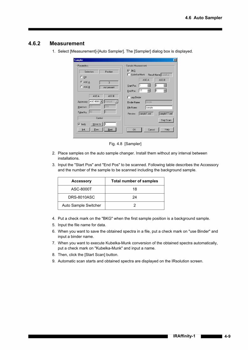
4.6 Auto Sampler
4-9IRAffinity-1
4.6.2 Measurement1. Select [Measurement]-[Auto Sampler]. The [Sampler] dialog box is displayed.
Fig. 4.8 [Sampler]
2. Place samples on the auto sample changer. Install them without any interval between installations.
3. Input the "Start Pos" and "End Pos" to be scanned. Following table describes the Accessory and the number of the sample to be scanned including the background sample.
4. Put a check mark on the "BKG" when the first sample position is a background sample.5. Input the file name for data.6. When you want to save the obtained spectra in a file, put a check mark on "use Binder" and
input a binder name.7. When you want to execute Kubelka-Munk conversion of the obtained spectra automatically,
put a check mark on "Kubelka-Munk" and input a name.8. Then, click the [Start Scan] button.9. Automatic scan starts and obtained spectra are displayed on the IRsolution screen.
Accessory Total number of samples
ASC-8000T 18
DRS-8010ASC 24
Auto Sample Switcher 2

4-10 IRAffinity-1
Chapter 4 Operations
4.6.3 The Way to Move Sample PositionThis section describes the way to move sample position.
Current positionThe current position is displayed at the "Position" part.
Relative movementMove to the Previous or Next position. Click the [Prev.] or [the Next] button at the [Control] part.
• When the current position is the last sample position of the ASC, the [Next] button moves to the first position (initialized position).
• When the current position is the first sample position (initialized position) of the ASC, the [Prev.] button moves to the last sample position.
Absolute movementMove to the specified position.Input the sample position number at the [Control] part, and then click the [Move to] button.
• If input number exceeds the "Maximum" of the ASC setting, an Error message is displayed.
Fig. 4.9 [Sampler] Dialog Box
Current Position
Position movement control

4.7 Precautions for Using Accessories
4-11IRAffinity-1
This section describes precautions when Accessories are used.
4.7.1 ATR-8200HAWhen the Flat Plate Press (Clamp) is mounted to the ATR-8200HA, because the top of the press is hitting the bottom of the sample compartment lid, the lid does not close. Purge tubes of the ATR-8200HA avoid the fluctuation of the air. Samples can be run with opening the sample compartment.
4.7.2 MIRacle A and DuraSamplIR IIA SeriesWhen the Sample Press (Clamp) is mounted to the MIRacle A or DuraSamplIR IIA series, because the top of the press is hitting the bottom of the sample compartment lid, the lid does not close. Purge tubes of the accessory avoid the fluctuation of the air. Samples can be run with opening the sample compartment.
4.7.3 ASC-8000T and Auto Sample SwitcherSamples must be fixed with the standard stop-rings or another parts to the ASC-8000T or Auto Sample Switcher. Otherwise, samples might be dropped by the vibration during moving the position.
4.7.4 Accessories Which Are Mounted to the Cassette (Sample Holder)When mounting accessories such as liquid cells in the cassette (sample holder), installation position is slightly misaligned because of the gap around the cassette. Please mount the accessory on the same position.Please use an optional sample holder (P/N 206-17384) when reproducibility such as quantitative analysis is required.
4.7.5 KBr Pellet, Liquid Cell, Sealed Cell, Fixed Thickness Cell Since the beam size in auto (open) as aperture is larger than one of KBr pellet (13, 5, 3 or 2 mmφ), Liquid cell, Sealed cell and Fixed thickness cell (10 × 22 mm), only part of the beam is used. In this case, noises are on the baseline of the obtained spectra. These noises may be reduced by scanning BKG and sample with smaller aperture setting such as 3.0, 2.1 and 1.5.
CAUTIONWipe the FTIR and/or inside of its sample compartment immediately, when they are wet by any liquid samples such as water, organic solvents, etc.The instrument could be damaged.
4.7 Precautions for Using Accessories

4-12 IRAffinity-1
Chapter 4 Operations
Unplug the power cord of IRAffinity-1 instead of turning off the power switch on the front panel, if IRAffinity-1 must be completely turned off in case of rising smoke, etc.
4.8 In Case of Emergency

5-1IRAffinity-1
Chapter 5Maintenance and Inspection
CONTENTS
5.1 Start-Up Inspection and Periodic Inspection..................................................................................5-25.2 When Not Using IRAffinity-1 for a Long Term (Over a Month) ......................................................5-75.3 For Brownout .................................................................................................................................5-85.4 Procedure to Replace Silica Gel....................................................................................................5-95.5 Dry Indicator ................................................................................................................................5-105.6 Self Diagnostics ...........................................................................................................................5-115.7 Cleaning the System....................................................................................................................5-165.8 Transporting the System..............................................................................................................5-175.9 Maintenance Parts and Consumable Parts .................................................................................5-18

5-2 IRAffinity-1
Chapter 5 Maintenance and Inspection
The following inspections are necessary to keep your FTIR condition. There are two types of inspection.
5.1.1 Start-Up InspectionStart-up inspection is an inspection before use your FTIR.
• Dry indicator check This check must be done before turning ON.• Silica gel check This check must be done before turning ON.• Power spectrum check
5.1.1.1 Dry Indicator Check
There are two indicators - an orange lamp as Dry indicator and a green lamp as Power indicator on the front. Dry indicator lights show the humidity in the interferometer of the FTIR even if the FTIR power is Off. Confirm that the Dry indicator is on.
If the Dry indicator does not light, check the connection of a power cord between FTIR and AC supply, and that the AC supply works normally. If above two check points are correct, the humidity in the interferometer is high and the optical elements might be damaged.In this case;
1. Disconnect the power cord immediately and do not use your IRAffinity-1.2. Remove the Top cover and replace the silica gel packages.3. Please contact your SHIMADZU representative.
Start-up inspection Is an inspection before use your FTIR.• Dry indicator check• Silica gel check• Power spectrum check
Periodic inspection Is an inspection to be done once a week even if your FTIR is not operated.• Dry indicator check• Silica gel check
WARNINGThe Start-up inspection and the Periodic inspection must be done!The Start-up inspection and the Periodic inspection must be done. If these checks are not done and Silica gel has been degraded for long time, the KBr beam splitter deliquesces and performance of the FTIR becomes low. In worst case, FTIR does not work. In such case, a SHIMADZU service engineer must replace the beam splitter and align the FTIR condition. Repairing costs are high.
NOTEThis check must be done before turning ON.
NOTEIRAffinity-1 includes a Dry unit to desiccate the interferometer and a Humidity sensor to monitor the humidity. Never cut the AC power to the IRAffinity-1, because these functions run on AC power.
5.1 Start-Up Inspection and Periodic Inspection

5.1 Start-Up Inspection and Periodic Inspection
5-3IRAffinity-1
Fig. 5.1 Dry Indicator
5.1.1.2 Silica Gel Check
Lift up the back side of the Top cover (Fig. 5.2) and then pull it up to remove the top cover. Confirm that the color of the Silica gel is blue not red.The color of Silica gels turns into red from blue as they absorb moisture. They should be replaced when the color has become lavender color (purple).Put the top cover on the FTIR after checking.
If the color of the Silica gel becomes red, the Dry unit does not work normally. The humidity in the interferometer becomes high and the optical elements will be damaged.In this case;
1. Disconnect the power cord immediately and do not use your IRAffinity-1.2. Remove the Top cover and replace the silica gel packages.3. Please contact your SHIMADZU representative.
NOTEThis check must be done before turning ON.
NOTEIRAffinity-1 includes a Dry unit to desiccate in the interferometer. It also includes Silica gel to provide for cutting AC power supply. Because the humidity inside of the interferometer is usually lower than 20% RH and Silica gel stops moisture absorption, replacement of Silica gel is not needed while the dry unit is working. Please check the color of the Silica gel periodically to provide for unusual situations.
Dry Indicator

5-4 IRAffinity-1
Chapter 5 Maintenance and Inspection
Fig. 5.2 Remove the Top Cover
Fig. 5.3 After Removing the Top Cover
5.1.1.3 Power Spectrum CheckFTIR performance is evaluated by measuring the power spectrum. The power spectrum gives the intensity at various wavenumbers. After ensuring that the sample chamber is empty, enter the following parameters in the Parameter Tab on the [Measurement] Tab Screen, and measure the power spectrum to verify the specifications.
In [Data] tab:
"Measuring mode": "Power"
"Resolution": "2 cm−1"
"Range": "4700-340 cm−1"
"N scans": "45" scans
"Apodization": "HAPP-GENZEL"
"Detector": "standard"
"Beam": "internal"
In [More] tab:
"Detector speed": "2.8 mm/sec"
Lift up to remove the Top cover.
Silica gel caseConfirm the color of the Silica gel inside

5.1 Start-Up Inspection and Periodic Inspection
5-5IRAffinity-1
The intensity specifications are given below.
1) There is an absorbance peak of water at 400 cm−1, so correct intensity of the power spectrum is not calculated. Thus the intensity of 403 cm−1 is used for evaluation of the power spectrum.
Fig. 5.4 Power Spectrum (Example)
If the intensity does not meet the specifications, or the energy at high wavenumbers (to 4600 cm−1) is extremely low, run [Auto adjustment] on the [Instrument] Menu, and reanalyze the spectrum. If the power spectrum does not improve after the "auto adjustment", the system may be damaged; contact your SHIMADZU representative. If the intensity remains zero, the light source may be disconnected or damaged; light source replacement or repair should be performed by a SHIMADZU service engineer.
Wavenumber (cm−1): Specification
4600: 10% or more of maximum
4000: 25% or more of maximum
3000: 50% or more of maximum
Wavenumber indicating the maximum intensity (2500 - 1800 cm−1):
50 or more
700: 10% or more of maximum
500: 2% or more of maximum
403 1): 0.5% or more of maximum
351: 0.01% or more of maximum

5-6 IRAffinity-1
Chapter 5 Maintenance and Inspection
5.1.1.4 Validation ProgramThe validation program inspects the FTIR condition instead of Power spectrum check.IRAffinity-1 provides the validation programs according to the Japanese Pharmacopoeia, European Pharmacopoeia and ASTM. Refer to the Instruction manual - validation program for detail.
Validation program for European Pharmacopoeia and Japanese PharmacopoeiaThe IRAffinity-1 can automatically execute the inspection in conformance to the European Pharmacopoeia 5.0 and the Fifteenth Edition of the Japanese Pharmacopoeia. This inspection evaluates the measurement data acquired by using polystyrene as sample. In this inspection, use polystyrene with thickness of approximately 40 μm. When traceability is required in the inspection result, separately purchase the standard sample supplied by NIST or its secondary standard, and use it in the inspection.The validation executed by this validation software conforms to the European Pharmacopoeia 5.0 and the Fifteenth Edition of the Japanese Pharmacopoeia. There are five validation items; power spectrum, resolution, wavenumber accuracy, wavenumber reproducibility and transmittance (absorbance) reproducibility. The performance of the FTIR-8400S is validated through comparison between the measurement result and the standard value.
Validation program for ASTMThe IRAffinity-1 can automatically execute the inspection in conformance to the ASTM E1421-94 ("Level Zero"). Use a polystyrene film in conformance to the Japanese Pharmacopoeia with thickness of approximately 40 μm. When traceability is required in the inspection result, separately purchase the standard sample supplied by NIST or its secondary standard, and use it in the inspection.Though the ASTM specifies the inspection technique and the contents, it does not specify the standard values. The initial standard values are specified by SHIMADZU.There are three parameters checked by this program: Energy Spectrum Test, One Hundred Percent Line Test, and Polystyrene Test.
5.1.2 Periodic InspectionThe Periodic inspection is an inspection to be done once a week even if your FTIR is not operated.
• Dry indicator check This check must be done before turning ON.• Silica gel check This check must be done before turning ON.
5.1.2.1 Dry Indicator CheckThis is same as 5.1.1.1 "Dry Indicator Check". See section 5.1.1.1.
5.1.2.2 Silica Gel CheckThis is same as 5.1.1.2 "Silica Gel Check". See section 5.1.1.2.

5.2 When Not Using IRAffinity-1 for a Long Term (Over a Month)
5-7IRAffinity-1
Even if the IRAffinity-1 is not used for long term, AC power must still be supplied. The Dry unit works, desiccating the inside of the interferometer and protecting the optical elements against humidity.Inspection according to the section 5.1.2 "Periodic Inspection" must be done once a week.
5.2 When Not Using IRAffinity-1 for a Long Term (Over a Month)

5-8 IRAffinity-1
Chapter 5 Maintenance and Inspection
When AC power cannot be supplied because of periodic inspection of utilities etc., the Dry unit does not desiccate. Replace Silica gel packages in the FTIR once a week during brownout.
5.3 For Brownout

5.4 Procedure to Replace Silica Gel
5-9IRAffinity-1
Replace Silica gel with following procedure;1. Lift up the back side of the Top cover (Fig. 5.5) and then pull it up to remove the top cover. You can see the
Silica gel case.2. Take off the 4 screws ((3) in Fig. 5.6) to fix the lid of the Silica gel case, and then take off the lid of the Silica
gel case ((2) in Fig. 5.6).3. Take all Silica gel out, and then put new 4 Silica gel packages in.4. Put the Silica gel case with 4 fixing screws.5. Insert the tip of the Top cover into the hole ((4) in Fig. 5.6), and then put it on the FTIR after replacement.
Fig. 5.5 Remove the Top Cover
Fig. 5.6 Silica Gel Case
5.4 Procedure to Replace Silica Gel
Lift up to remove the Top cover.
(1)
(3)
(2)
(4)

5-10 IRAffinity-1
Chapter 5 Maintenance and Inspection
IRAffinity-1 has two Indicators - the Power indicator (green) and the Dry indicator (orange) - on the front panel. The Power indicator lights up when the switch is turned on. The Dry indicator lights up when humidity in the interferometer is low enough.The IRAffinity-1 keeps the inside of the interferometer at low humidity by driving the dry unit and monitors humidity inside of the interferometer, even while the IRAffinity-1 is not used. Accordingly, always let the power plug of the IRAffinity-1 be connected to the AC power supply to keep the power supply. Confirm that the orange Dry indicator is lit.
If the Dry indicator is not lit, please confirm following checkpoints.1. AC for IRAffinity-1 is correctly the connected to AC line.2. The AC line is correctly alive.
If the Dry indicator is not lit even if above points are not troubled, it may be caused by hardware trouble in the IRAffinity-1. In this case;
1. Unplug the AC power cord of IRAffinity-1 immediately, and do not use IRAffinity-1.2. Open the top cover and install NEW SILICA GELs immediately.3. Then contact your SHIMADZU representative.
Fig. 5.7 Front View of IRaffinity-1
5.5 Dry Indicator
Dry IndicatorPower Indicator

5.6 Self Diagnostics
5-11IRAffinity-1
The IRAffinity-1 has a self-diagnosis function. The IRAffinity-1 automatically checks its own status during operation or startup. When all items are judged OK, the IRAffinity-1 can be used normally. The contents of the self-diagnosis are described below.
Items checked when the IRAffinity-1 starts up or when [Measurement]-[Diagnostics] is executed:1. Laser lighting2. Light source lighting3. Humidity level inside of the interferometer4. Fixed mirror piezo actuator voltage5. Infrared power spectrum shape6. Presence of Auto-sampler
Items always checked while the IRAffinity-1 is operating in Status window:1. Laser lighting2. Light source lighting3. Humidity level inside the interferometer4. Status of the beam switching kit5. Presence of Auto-sampler6. Presence of QuickStart accessory and its information
5.6.1 Self Diagnostics during InitializationSelecting the [Measurement]-[Initialize] initializes IRAffinity-1 and executes self diagnostics. The result of the self diagnostics is recorded on the operation log.When the test item passes, OK is recorded on the log. If a item failed, Fail is recorded.
Fig. 5.8 Log Screen during Initialization
5.6 Self Diagnostics
[Date & Time] Initializing: IRAffinity-1[Date & Time] Init delay: 10 s[Date & Time] Analyzing Piezo Voltage [101]Setting aperture auto[Date & Time] Piezo Voltage [101] OK[Date & Time] Analyzing Piezo Voltage [102][Date & Time] Piezo Voltage [102] OKPerforming diagnostic power measurementSetting aperture auto[Date & Time] Power diagnostics OK (XX, XX, XX)[Date & Time] INIT success

5-12 IRAffinity-1
Chapter 5 Maintenance and Inspection
If "Laser lighting" or "Light source lighting" failed, each part must be replaced. Please contact your SHIMADZU representative.If the "Humidity level inside of the interferometer" failed, the humidity in the interferometer has become too high and the optical elements may be damaged.
1. Disconnect the power cord immediately and do not use your IRAffinity-1.2. Remove the Top cover and replace silica gel packages.3. Please contact your SHIMADZU representative.
Because "Infrared power spectrum shape" measures a power spectrum with no sample in the sample compartment, remove any samples and accessories from the sample compartment. If this test was failed by interrupting the beam, you can execute Self diagnostics after initialization. If this test was failed with empty sample compartment, confirm the scan parameters first. Then execute [Measurement]-[Auto Adjust]. If the test is still failed after auto adjustment, the Beam splitter might be damaged. Please contact your SHIMADZU representative.
5.6.2 Describing the Diagnostic ScreenInspect the equipment status using the [Measurement]-[Diagnostic] command. Select this command to display the following screen. This section describes this screen.
Fig. 5.9 [IRAffinity-1 Diagnostic] Screen
[Unit connected]
ID Equipment name
RAM (KB) RAM size of Main/Zeta CPU
I/F Operating status of interface
Version ROM/PRG version No. of Main/Zeta CPU
Check Sums Check sums of Main/Zeta CPU

5.6 Self Diagnostics
5-13IRAffinity-1
[Equipment]
[Measurements]
[Button]
If "Laser lighting" or "Light source lighting" failed, each part must be replaced. Please contact your SHIMADZU representative.If the "Humidity level inside of the interferometer" failed, the humidity in the interferometer has become too high and the optical elements may be damaged.
1. Disconnect the power cord immediately and do not use your IRAffinity-1.2. Remove the Top cover and replace silica gel packages.3. Please contact your SHIMADZU representative.
Because "Infrared power spectrum shape" measures a power spectrum with no sample in the sample compartment, remove any samples and accessories from the sample compartment. If this test was failed by interrupting the beam, you can execute Self diagnostics after initialization. If this test was failed with empty sample compartment, confirm the scan parameters first. Then execute [Measurement]-[Auto Adjust]. If the test is still failed after auto adjustment, the Beam splitter might be damaged. Please contact your SHIMADZU representative.
Laser Laser lighting
Mirror Mirror stability
Beam Splitter Beam splitter type
Light Source Light source lighting
External Beam Status of external beam (exist/ not exist)
ASC A Connection status of auto sample changer A
N2 Presence/absence of liquid nitrogen
Detector Condition of detector
Accessory Name of connected accessory
Humidity Humidity inside of interferometer
Power Spectrum Power spectrum inspection (executed/not executed)
Wavenumber Wavenumber to check intensity
Standard Judgment reference intensity in each wavenumber
Measured Actual measured intensity
Judge OK/NG in each wavenumber
Piezo Voltage Piezo voltage (inspected or not)
101/102 Results of Piezo voltage inspection of each code No. (OK/NG)
(Status column) Displays the inspection content which is running
[Done] Click this button to close the screen.
[Report] Click this button to output results to a text file.

5-14 IRAffinity-1
Chapter 5 Maintenance and Inspection
5.6.3 Status MonitorThe status monitor show the condition of the FTIR and information of installed accessory. The status window shows following items.
Fig. 5.10 Status Monitor
Laser Indicates whether the He-Ne laser is operating.Green The He-Ne laser is operating normally.Red The He-Ne laser is not operating.
Please contact your SHIMADZU representative.
Lamp Indicates whether the Infrared light source is operating.Green The light source is operating normally.Red The light source is not operating.
Please contact your SHIMADZU representative.
Humidity Indicates the humidity level in the interferometer.Green The humidity in the interferometer is low enough.Red The humidity in the interferometer is high. The dry unit might
break down.1. Disconnect the power cord immediately and do not use your
IRAffinity-1.2. Remove the Top cover and replace silica gel packages.3. Please contact your SHIMADZU representative.
SW Indicates presence and setting of the Beam switching kit.None The beam switching kit is not installed.Green The beam switching kit is installed and working normally.
Internal; IR beam is introduced to the sample compartment and the standard detector can be used.
External; IR beam is introduced to the outside and the optional detector such as Microscope can be used.
Validate; A polystyrene film is inserted in the beam. This mode is for automatic validation.
Red The beam switching kit is installed but not working.Please contact your SHIMADZU representative.

5.6 Self Diagnostics
5-15IRAffinity-1
ASC-A Indicates presence of the auto-sampler.None Auto-sampler is not installed.Yellow Auto-sampler is not initialized.Green Auto-sampler was initialized and is ready to be used.
Accessory Indicates presence and information of the installed accessory.None Accessory is not installed.Green Accessory is installed and ready to be used.
Its serial number is shown.

5-16 IRAffinity-1
Chapter 5 Maintenance and Inspection
If the outside of the interferometer becomes dirty, wipe it clean with a soft cloth or tissue; soak the cloth in water or detergent, and wring it out. Do not use organic solvents, such as thinner or benzene, and avoid contact with mirrors and other internal components.
NOTEDo not spill water or solvents on the system; spills may result in system damage, fire or electric shock.
5.7 Cleaning the System

5.8 Transporting the System
5-17IRAffinity-1
WARNINGTo ensure safe operation, contact your SHIMADZU representative for installation, adjustment, or re-installation after moving the instrument to a different site.
5.8 Transporting the System

5-18 IRAffinity-1
Chapter 5 Maintenance and Inspection
(*) The supplemental disk may not be included or the part number may be changed for upgraded versions.
Name Unit Part No.
1 Silica gel 1 200-53655
2 Polystyrene film (approx. 50 μm thickness) 1 202-30689-01
3 Standard Cassette (Slide-mount sample holder) 1 206-70001
4 Optional Cassette (Slide-mount sample holder) 1 206-17384
5 Screw for Slide-mount 1 037-02820-18
6 Sample compartment cover 1 206-71762-12
7 Sample compartment sub-cover 1 206-71764-10
8 Light Source Assy 1 206-70106-91
9 DLATGS Detector MTG-21 1 206-72234
10 Laser Assy 1 206-73369-91
11 Laser Power Supply Assy 1 206-72343-91
12 Piezo Assy 1 206-17317
13 Moving Mirror Assy 1 206-17331-05
14 Fixed Mirror Assy 1 206-70012-91
15 ASC cable 1 206-73433-91
16 AC cable (for 100 to 120 V) 1 071-60816-12
AC cable (220 to 240 V) 1 071-60825-51
17 Fuse 4 A 1 072-02004-22
18 Dry Unit Assy 1 206-73531-91
19 PCB Assy Power 1 206-73374-91
20 PCB ASSY CPU 1 206-73409-91
21 PCB ASSY LASER DETEC 1 206-73419-91
22 IRsolution 1 206-73800-91
23 Supplemental Disk(*) 1
NOTE• He-Ne laser assy is a consumable part. Replacement may be required every year. This however
depends on condition.• Dry unit assy is a consumable part. Replacement may be required periodically year. This however
depends on condition.
5.9 Maintenance Parts and Consumable Parts

6-1IRAffinity-1
Chapter 6Troubleshooting
CONTENTS
6.1 Error Message Table .....................................................................................................................6-26.2 Error Message Shown in the "Status Window"..............................................................................6-36.3 What's Happening? .......................................................................................................................6-66.4 Confirming the Power Selector Switch and Fuse ..........................................................................6-9

6-2 IRAffinity-1
Chapter 6 Troubleshooting
When measurement parameters have some mismatch or the instrument has some adjustment error, these error messages are indicated on the Pop-up window.This table shows error message meanings and how to operate. Refer to this table and operate again.
Error Message Meanings and Operation
None of the available background matches the sample parameters.
There is no background data stored which matches the sample measurement (%T or Abs).When you change parameters such as "Resolution", background data must be measured, then sample measurement becomes available.
Can't open the File File to be loaded might be set as "Read only"? If so, file can not be opened. If not, the contents of the file may be broken.
XXX(File name) already exist.Please choose a different file name!
When GLP mode, File overwriting is prohibited.Change file name and save again.
XXX to XXXX wavenumber should be inputted.
Wavenumber range value in measurement parameter is out of the range which is set to the beam splitter used. Input correct value.
6.1 Error Message Table

6.2 Error Message Shown in the "Status Window"
6-3IRAffinity-1
When measurement parameters have some mismatch or your instrument has some adjustment error, these error messages are indicated in the "Status Window".This table shows error message meanings and how to operate. Please read the message and refer to operate. If no improvement is obtained in spite of this operation, your instrument may be damaged. Please contact Shimadzu branch.
Error Message Meanings and Operation
No Background spectrum!Measurement aborted.
There is no background data stored which matches the sample measurement (%T or Abs).When you change parameters such as "Resolution", background data must be measured then sample measurement becomes available.
No AIM device on When mapping measurement, AIM microscope is not connected or is just operating other task. Confirm Mapping measurement is finished then operate again.
Option Detector is not mounted When Option detector is not mounted and "Option1" detector is selected. Confirm the measurement parameters.
Parameter check Error. There is some mismatch in the measurement parameters. Confirm the measurement parameters.
There is some mismatch in the measurement parameters. Confirm the measurement parameters.
When detector parameter is set to "Option2", liquid nitrogen sensor is active and if there is no liquid N2 in the MCT dewer, this error message is shown. Confirm that MCT dewer is filled with liquid N2 and that cable is connected.
Diagnostic Power measurement failed Power spectrum shape check in diagnostics has failed. Execute [Measurement]-[Auto Adjust] and try again.
Could not retrieve diagnostic power results. Power spectrum shape check in diagnostics can not be completed. Execute [Measurement]-[Auto Adjust] and try again.
Piezo voltage is out of range. Piezo voltage check in diagnostics has failed. Execute [Measurement]-[Auto Adjust] and try again.
Piezo voltage can not be obtained. Piezo voltage check in diagnostics can not be completed. Execute [Measurement]-[Auto Adjust] and try again.
Not enough memory available! Out of memory
The remaining memory in your PC is insufficient. If you are using other applications on the PC, terminate other applications and restart the PC.
Failure of mirror drive in the interferometer. Moving mirror movement has failed. Execute [Measurement]-[Auto Adjust] and try again
Moving Mirror Error X Moving mirror movement has failed. Execute [Measurement]-[Auto Adjust] and try again
Invalid QC counter The QC counter to manage the moving mirror position shows an abnormal value. Scan samples isolated from vibrations.
QC Timeout Error The moving mirror could not finish its operation. Execute [Measurement]-[Auto Adjust].
6.2 Error Message Shown in the "Status Window"

6-4 IRAffinity-1
Chapter 6 Troubleshooting
Error Message Meanings and Operation
A/D out of range Measured data beyond the A/D converter range limit. When using standard detector, check if transmittance of the sample is changed, or with MCT detector, reduce the light intensity using the aperture, etc.
Interferogram beyond A/D converter limit Measured data beyond the A/D converter range limit. When using standard detector, check if transmittance of the sample is changed, or with MCT detector, reduce the light intensity using the aperture, etc.
Offset value beyond A/D converter limit Measured data beyond the A/D converter range limit. When using standard detector, check if transmittance of the sample is changed, or with MCT detector, reduce the light intensity using the aperture, etc.
No centerburst detected Centerburst of measured interferogram can not be detected. Execute [Measurement]-[Auto Adjust].
Vertical value beyond the limit The parameters of fixed mirror beyond the software limit. Execute [Measurement]-[Auto Adjust].
Horizontal value beyond the limit The parameters of fixed mirror beyond the software limit. Execute [Measurement]-[Auto Adjust].
Optim. vertical value beyond the limit after [Auto Adjust]
The parameters of fixed mirror adjustment beyond the software limit. Execute [Measurement]-[Auto Adjust].
Optim. horizontal value beyond the limit after [Auto Adjust]
The parameters of fixed mirror adjustment beyond the software limit. Execute [Measurement]-[Auto Adjust].
Fixed mirror adjustment failed. Fixed mirror adjustment has failed. Execute [Measurement]-[Auto Adjust].
No interferogram FFT in manipulation must be executed to IFG data.
Recalculation can not be performed (no data)
There is no data for recalculate. Reload the data to be recalculated.
ASC-A initialization error Error occurs when initializing Auto sample changer connected to the connector A. Confirm the connection of ASC.
ASC-B initialization error Error occurs when initializing Auto sample changer connected to the connector B. Confirm the connection of ASC.
Selected ASC is not detected. Selected ASC is not detected. ASC cable might be disconnected.
Failure in initializing of ASC motor System fails initialization of ASC motor. Check the connection of ASC cable.
Failure in initializing of Beam setting motor System fails initialization of Beam switching motor. Please contact your SHIMADZU representative.
Lamp offline Light source inoperative. Please contact your SHIMADZU representative.

6.2 Error Message Shown in the "Status Window"
6-5IRAffinity-1
There are more error messages, but in normal use they seldom appear. If undefined errors in the table above frequently occur, the instrument may have a software or hardware problem. Please contact the Shimadzu branch.
Error Message Meanings and Operation
Laser offline Laser inoperative. Please contact your SHIMADZU representative.
Laser Failure If the laser indicator of status window shows red, laser is damaged. Call Shimadzu branch.
No beamsplitter Beamsplitter is not mounted or not mounted correctly. Please check.
Lamp offline. Please change it. If the lamp indicator of status window shows red, selected lamp is disconnected. Call Shimadzu branch.
Timeout on initialization During initialization, communication between interferometer and PC is not active. Check if interferometer power is not ON or USB cable is disconnected.
Instrument Timeout Error Communication between interferometer and PC is not active. Check if interferometer power is not ON or USB cable is disconnected.
No valid range object Wavenumber range set file ("*.rng") may be damaged. Please delete the ".rng" file and make a new range set file.
N2 information in EEPROM is invalid Information for the liquid nitrogen on EEPROM was abnormal. Please contact your SHIMADZU representative.
Evaluation Scan Error: Internal counter exceeded
Evaluation of data detected abnormality.
External trigger is not detected. Measurement is aborted.
Outside trigger signal could not be detected.
Measured data intensity is too high (×16) Intensity of the data was too high. Gain setting was too high or excessive noise was detected.
Measured data intensity is too low The light at the detector was too weak.

6-6 IRAffinity-1
Chapter 6 Troubleshooting
This section lists troubles that you may have during the operating of the IRAffinity-1 and describes their reasons and solutions. Refer to Chapter 5 and 6 to solve these troubles. If the trouble cannot be solved, please contact your SHIMADZU representative.
6.3.1 Abnormal Behavior during InitializationPhenomena
1. The message "Power diagnostic Failed" was displayed at the Initialization.2. [Auto Adjust] was executed during Initialization.
Reason1. Initialization was executed when any accessory or sample is set on the sample compartment,
or when the "beam" was set to [External].Solution
1. Check following items.• No accessory or no sample is set on the sample compartment.• Set the "beam" to [Internal] when the optional Beam Switching Kit was installed.
2. Execute the [Measurement]-[Auto Adjust].3. Turn off the FTIR once, and then turn it on again. Execute [Measurement]-[Initialize] again.4. If the trouble can not be solved, please contact your SHIMADZU representative.
6.3.2 The Signal Intensity of the Power Spectrum Remains Zero.Phenomena
1. The Signal intensity of the power spectrum remains zero.Reason
1. The light source is disconnected.2. The fuse blew.3. Selection of the detector is wrong.4. Something, which intercepts the light path, is in the sample compartment.5. The infrared interference has shifted significantly.
Solution1. The light source is disconnected.
• Infrared source has become inoperative, if the "Lamp" on the status monitor is red.• If it is not lit, the light source replacement by a service engineer is required. Please
contact Shimadzu.2. The fuse has blown.
• The fuse on the Power board or in the Transformer has blown. Please contact your SHIMADZU representative.
3. Selection of the detector is wrong.• Select collect detector. Set "standard" for inside detector or "option2" for IR microscope
and Second sample compartment.4. Something, which intercepts the light path, is in the sample compartment.
• Open the sample compartment or set correct sample on the accessory.5. The infrared interference has shifted significantly
• Execute [Measurement]-[Auto Adjust].• If problem is not solved, please contact your SHIMADZU representative.
6.3 What's Happening?

6.3 What's Happening?
6-7IRAffinity-1
6.3.3 A Part of the Mirror Is a Little White.Phenomena
1. A Part of the Mirror is a little white.Reason
1. It seems to be the result of the heat of the infrared light source for an extended time.Solution
Conduct the performance check according to the section 5.1.1.3 or the section 5.1.1.4.
If this specification is satisfied, there is no problem for the measurement and you can continue to use it.
If not satisfied, execute the [Measurement]-[Auto Adjust] once, then perform the performance check again.
The mirror in the interferometer may become opaque after being used for a long time. This is caused by the heat of the light source. Usually, however, this doesn't cause a problem in a measurement of μm order in the infrared wavelength region.The FTIR spectrophotometer has several mirrors inside. Never wipe the mirror surface with cloth or cleaner even if these mirrors are contaminated with dust. It may damage the mirror surface and lower the intensity of the infrared signal (the influence is especially large in the short wavelength region), resulting in an adverse effect to the measurement.
CAUTIONIf vapors of any organic halide, such as difluoromethane (CH2F2), dichloromethane (CH2Cl2), chloroform (CHCl3), or carbon tetrachloride (CCl4) enter the interferometer, they are decomposed by the heat of the light source to highly caustic hydrogen halides such as Hydrofluoric acid (HF), Hydrochloric acid (HCl), etc. Mirrors, other optical elements, screws and another parts in the interferometer might be damaged. Please prevent the entry of organic halide vapors into the interferometer by installing a local ventilation system at the FTIR sample compartment, or purging the interferometer with dried air or N2 gas, when you run samples that include volatile organic halide compounds.

6-8 IRAffinity-1
Chapter 6 Troubleshooting
6.3.4 Power Spectrum Becomes too Small, or Fluctuates.Phenomena
1. Power spectrum becomes smaller than ones when IRAffinity-1 was installed.2. Power spectrum becomes small in short term (a day to a week). Power spectrum fluctuates.
Reason1. Deterioration because of long term use2. Trouble with the power board3. Trouble with the detector
Solution1. Deterioration because of long term use
• Execute the [Measurement]-[Auto Adjust].• When power spectrum does not fluctuate in short term, execute a Japanese or European
Pharmacopoeia. The FTIR is normal when validation passes.When power spectrum fluctuates in short term, check following items.
2. Trouble with the power board• The power board might be inoperative. Please contact your SHIMADZU representative.
3. Trouble with the detector• The detector might be inoperative. Please contact your SHIMADZU representative.

6.4 Confirming the Power Selector Switch and Fuse
6-9IRAffinity-1
1. The setting of the input power for the interferometer unit of IRAffinity-1 is normally adjusted to the supply voltage in the area where the equipment is used. By using the voltage selector switch and by changing the fuse and AC cable of the AC inlet, the voltage of 100 V, 120 V, 220 V, or 230 V AC can be used. Before use, check that the power supply switch indicates the supply voltage used. For input of 220 VAC, use the inlet voltage at 230 VAC.
2. Follow the procedure shown below for changing the voltage or replacing the fuse.
CAUTIONRating and type of fuseBe sure to replace the fuse specified as below.Part No. 072-02004-22, 250 V, 4.0 AT
Fig. 6.1 (a)
1. Be sure to disconnect AC cable. Insert the Fillister head screwdriver, softly twist it to open the lid of the AC inlet.
Fig. 6.1 (b)
2. To change the setting of voltage setting drum, once remove the drum.
Fig. 6.1 (c)
3. Mount the drum so that the display of the set voltage is arranged to the upper portion.
Fig. 6.1 (d)
4. Place your finger to the ↓ lever to pull out the fuse box. If the fuse is not suitable or is broken, put the new and correct type of fuse in the fuse box and return it to the previous status. Put it so that the arrow of the fuse box is set at ↓ direction.
6.4 Confirming the Power Selector Switch and Fuse

6-10 IRAffinity-1
Chapter 6 Troubleshooting
Fig. 6.1 (e)
5. Close the lid of the AC inlet.
Place the interferometer so that the front face is placed toward you after the works above are completed.

7-1IRAffinity-1
Chapter 7Materials for Infrared Analysis
CONTENTS
7.1 Materials for Infrared Analysis .......................................................................................................7-27.2 Characteristics of Materials ...........................................................................................................7-37.3 Optical Materials in IRAffinity-1......................................................................................................7-57.4 Material Safety Data Sheet............................................................................................................7-6

7-2 IRAffinity-1
Chapter 7 Materials for Infrared Analysis
Listed materials are used in IRAffinity-1 and their accessories. Used materials are depended on the equipment.They are usually used as windows or ATR prisms. Selection of materials are based on wavenumber range and physical/chemical characteristics of samples.This section describes typical characteristics of some materials.Some of the materials are used only rarely due to the difficulty of processing and high-cost.
Table 7.1 List of Typical Materials for Infrared Analysis
%Transmission value given are typical ones, in the wavenumber range applicable to the respective materials, including the loss due to surface reflection.
MaterialWavenumber
range cm−1 (μm)
Refractive index
1000 cm−1
Water solubility at 20 °C
g/100 gH2O
% transmission (thickness)
Max. Temp. (Melting point)
Knoop hardness
KBr 40000~340 (0.25~29.4) 1.52 65 90
(5 mm)300
(730)7.0
(100 g)
NaCl 50000~600 (0.2~16.6) 1.49 36 90
(5 mm)400
(801)18.2
(100 g)
KCl 40000~500 (0.25~20.0) 1.46 34 90
(10 mm) (776) 9.3 (100 g)
CsI 33000~200 (0.3~50.0) 1.74 44 90
(5 mm)200
(621) −
KRS-5 (TlBr+TlI)
16600~250 (0.6~40.0) 2.37 0.05 70
(2 mm)200
(414) 40.2
ZnS 10000~725 (1.0~13.3) 2.2 Insoluble 70
(1 mm)
300 (1180
sublimate)354
ZnSe 10000~550 (1.0~18.1) 2.4 Insoluble 65
(1 mm)350
(1700) 250
BaF250000~770 (0.2~12.9) 1.42 0.004 90
(1 mm)500
(1280)82
(500 g)
CaF250000~1100
(0.2~9.0) 1.39 Insoluble 95 (3.6 mm)
900 (1402)
158 (500 g)
Si 8000~660 (1.25~15.1) 3.4 Insoluble 55
(2.5 mm)300
(1420) 1150
Ge 5500~660 (1.8~16.6) 4 Insoluble 50
(2 mm)270
(936) 24
Diamond Type II
40000~12.5 (0.25~800) 2.38 Insoluble 70
(1 mm) (400) 10 Mohs scale
SiO2 (Fused Silica)
50000~2500 (0.20~4.0)
1. 42 (3000 cm−1)
Insoluble 85 (1 mm) 1170 softens 500
7.1 Materials for Infrared Analysis

7.2 Characteristics of Materials
7-3IRAffinity-1
Only the main characteristics of the materials listed in Table 7.1 are described below.The Clean-Up lists present only the representative solvents used to wash the material. Even if a solvent is listed as Clean-Up, confirm that the solvent does not react with the samples.The Harm solvents can destroy the materials through corrosion or dissolving.Some solvents not listed as Harm can be harmful to the materials.
Table 7.2 Characteristics of Materials
Material Characteristics Clean-Up Harm
KBrPotassium bromide
Low cost and wide wavenumber range.Easy to process with alcohol anhydride.Most popularly used.High mechanical strength.Store under humidity conditions lower than 50%.
chloroformcarbon tetrachloride
aqueous solutionlower alcohol
NaClSodium chloride
Most inexpensive.Wide wavenumber range.Store under humidity conditions lower than 50%.
chloroformcarbon tetrachloride
aqueous solutionlower alcohol
KClPotassium chloride
Similar characteristics as NaCl and KBr.Not popularly used.
chloroformcarbon tetrachloride
aqueous solutionlower alcohol
CsICesium iodide
Soft and hence liable to injure.Applicable to analysis in far-infrared region.Highly deliquescent.Store under humidity conditions lower than 40%.
chloroformcarbon tetrachloride
aqueous solutionlower alcohol
KRS-5 (TlBr+TlI)Thallium bromide-iodide
Wide wavenumber range.High refractive indexMost widely used for ATR prism.Almost insoluble in water.Toxic; must be processed at an authorized manufacturer's site.
chloroformcarbon tetrachloridexylene
lower alcoholacetoneammonium salt solutionsulfuric acidammoniaEDTAa solution of a compound that reacts with thallium to form complex
ZnSZinc sulfide
Insoluble in water.Resistant against mechanical and thermal shocks.High refractive index.Effectively used for evaporation depositing.
acetonealcohol
acidic solution
7.2 Characteristics of Materials

7-4 IRAffinity-1
Chapter 7 Materials for Infrared Analysis
Material Characteristics Clean-Up Harm
ZnSeZinc selenide
Insoluble in water.Resistant against weak acidic or alkaline solution.Applicable pH range: 5 to 9.High refractive index.Used for ATR prism.Highly toxic H2Se gas may be generated if acidic samples are run with ZnSe prisms or windows.
acetonewater
strong acidic or alkaline solution
BaF2Barium fluoride
Soluble in ammonium salt solution.Usable up to 500 °C.Almost insoluble in water.
acetonewater
acidic solutionammonium salt solution
CaF2Calcium fluoride
Soluble in ammonium salt solution.Resistant against acidic or alkaline solution.Hard, high mechanical strength.Suitable for high-pressure cell
SiSilicon
Widely used as the material for semiconductors.Rarely used as window material.Ge can substitute Si as window material.
acetonewater
HF+HNO3
GeGermanium
Widely used as the material for semiconductors.Easily processed to be lenses.High refractive index, suitable as the material for as ATR prism used in analysis of high refractive samples.Insoluble in water.
toluenewater
Hot sulfuric acid
Diamond Type II Harder than any other materials.Applicable to wavelength range from UV to far-IR, though a gradual absorption is seen in the range from 30000 to 1500 cm−1.Natural diamond is classified as Type I and Type II, and only Type II is used for IR analysis.Extremely expensive.Recommended for the window of high-pressure cell.
ethanolacetone
SiO2 (Fused Silica) Effective for analysis in the UV and visible regions.Though useful up to 4 nm in the IR region, this is material ensures high stability and is easy to process.
ethanolacetone

7.3 Optical Materials in IRAffinity-1
7-5IRAffinity-1
Fig. 7.1 shows optical materials in the IRAffinity-1.
Fig. 7.1 Optical Materials in IRAffinity-1
7.3 Optical Materials in IRAffinity-1
Beam splitter(Ge on KBr window)
Window(KRS-5 window)
Compensator(KBr window)
Detector(KRS-5 windows)

7-6 IRAffinity-1
Chapter 7 Materials for Infrared Analysis
7.4.1 KRS-5KRS-5 consists of Thallium bromide (TlBr) and Thallium iodide (TlI).
7.4.1.1 Thallium Bromide (TlBr)
1. Identification of substance
Trade name: Thallium (I) bromide
2. Composition/Data on components
Name: Thallium (I) bromideTlBr
CAS No.: 7789-40-4EINECS Number: 232-163-0EC Number: 081-002-00-9
3. Hazards identification
Hazard designation:T+ Very toxicN Dangerous for the environment
Information pertaining to particular dangers for man and environmentR 26/28 Very toxic by inhalation and if swallowed.R 33 Danger of cumulative effects.R 51/53 Toxic to aquatic organisms, may cause long-term
adverse effects in the aquatic environment.
4. First aid measures General information:Instantly remove any clothing soiled by the product.Remove breathing apparatus only after soiled clothing has been completely removed.In case of irregular breathing or respiratory arrest provide artificial respiration.
After inhalation: Supply fresh air. If required, provide artificial respiration.Keep patient warm. Consult doctor if symptoms persist.Seek immediate medical advice.
After skin contact: Instantly wash with water and soap and rinse thoroughly.Seek immediate medical advice.
After eye contact: Rinse opened eye for several minutes under running water. Then consult doctor.
After swallowing: Do not induce vomiting; instantly call for medical help.Seek immediate medical advice.
5. Fire fighting measures
Suitable extinguishing agents:Use fire fighting measures that suit the environment.
Special hazards caused by the material, its products of combustion or flue gases:Can be released in case of fire:Toxic metal oxide smokeHydrogen bromide (HBr)
Protective equipment:Wear self-contained breathing apparatus.Wear full protective suit.
7.4 Material Safety Data Sheet

7.4 Material Safety Data Sheet
7-7IRAffinity-1
6. Accidental release measures
Person-related safety precautions:Wear protective equipment. Keep unprotected persons away.Ensure adequate ventilation
Measures for environmental protection:Do not allow material to be released to the environment without proper governmental permits.
Measures for cleaning/collecting:Dispose of contaminated material as waste according to item 13.Ensure adequate ventilation.
Additional information:See item 7. for information on safe handling.See item 8. for information on personal protection equipment.See item 13. for information on disposal.
7. Handling and storage
Handling:Information for safe handling:
Keep containers tightly sealed.Store in cool, dry place in tightly closed containers.Ensure good ventilation/exhaustion at the workplace.Open and handle container with care.
Information about protection against explosions and fires:The product is not flammable
StorageRequirements to be met by storerooms and containers:
No special requirements.Information about storage in one common storage facility:
Store away from oxidizing agents.Store away from air.Store away from water.
Further information about storage conditions:Store under dry inert gas.Protect from humidity and keep away from water.This product is hygroscopic.Keep container tightly sealed.Store in cool, dry conditions in well sealed containers.Store in a locked cabinet or with access restricted to technical experts or their assistants.

7-8 IRAffinity-1
Chapter 7 Materials for Infrared Analysis
8. Exposure controls and personal protection
Additional information about design of technical systems:Properly operating chemical fume hood designed for hazardous chemicals and having an average face velocity of at least 100 feet per minute.
Components with critical values that require monitoring at the workplace:Thallium and soluble thallium compounds (as Tl) mg/m3
ACGIH TLV 0.1 (skin)Austria MAK 0.1Belgium TWA 0.1 (skin)Denmark TWA 0.1 (skin)Finland TWA 0.1 (skin)France VME 0.1Germany MAK 0.1Ireland TWA 0.1 (skin)Korea TLV 0.1 (skin)Netherlands MAC-TGG 0.1 (skin)Norway TWA 0.1Poland TWA 0.1; 0.3-STELSwitzerland MAK-W 0.1 (skin)United Kingdom LTEL 0.1 (skin)USA PEL 0.1 (skin)
Additional information:No data
Personal protective equipmentGeneral protective and hygienic measures
The usual precautionary measures should be adhered to in handling the chemicals.Keep away from foodstuffs, beverages and food.Instantly remove any soiled and impregnated garments.Wash hands during breaks and at the end of the work.Store protective clothing separately.
Breathing equipment:Use breathing protection with high concentrations.
Eye protection: Safety glassesBody protection: Protective work clothing.

7.4 Material Safety Data Sheet
7-9IRAffinity-1
9. Physical and chemical properties:
General InformationForm: -Colour: -Smell: Not determined
Change in conditionMelting point/Melting range: 460 °C ((approx))Boiling point/Boiling range: Not determinedSublimation temperature / start: Not determined
Flash point: Not applicableIgnition temperature: Not determinedDecomposition temperature: Not determinedDanger of explosion: Product is not explosive.Critical values for explosion:
Lower: Not determinedUpper: Not determined
Steam pressure: Not determinedDensity at 20 °C 7.5 g/cm3
Solubility in / Miscibility with Water: Insoluble
10. Stability and reactivity
Thermal decomposition / conditions to be avoided:No decomposition if used and stored according to specifications.
Materials to be avoided:Oxidizing agentsAlkali metalsWater/moistureAir
Dangerous reactions:No dangerous reactions known
Dangerous products of decomposition:Toxic metal oxide smokeHydrogen bromide
11. Toxicological information
Acute toxicity:Primary irritant effect:on the skin: Irritant for skin and mucous membranes.on the eye: Irritant effect.Sensitization: No sensitizing effect known.Additional toxicological information:
To the best of our knowledge the acute and chronic toxicity of this substance is not fully known.No classification data on carcinogenic properties of this material is available from the EPA, IARC, NTP, OSHA or ACGIH.

7-10 IRAffinity-1
Chapter 7 Materials for Infrared Analysis
12. Ecological information
Ecotoxical effects:Remark: Toxic for fishGeneral notes: Water danger class 3 (Self-assessment): extremely
hazardous for water.Do not allow product to reach ground water, water bodies or sewage system, even in small quantities.Danger to drinking water if even extremely small quantities leak into soil.Also poisonous for fish and plankton in water bodies.Do not allow material to be released to the environment without proper governmental permits.Toxic for aquatic organisms
13. Disposal considerations
Product:Recommendation
Consult state, local or national regulations for proper disposal.Hand over to disposers of hazardous waste.Must be specially treated under adherence to official regulations.
Uncleaned packagings:Recommendation
Disposal must be made according to official regulations.
14. Transport information
Land transport ADR/RID and GGVS/GGVE (cross-border/domestic)ADR/RID-GGVS/E Class: 6.1 (T5) Toxic substances.Kemler Number: 60UN-Number: 1707Packaging group: IILabel 6.1Designation of goods: 1707 THALLIUM COMPOUNDS, N.O.S.
(thallium (I) bromide)Maritime transport IMDG/GGVSea:
IMDG/GGVSea Class: 6.1UN Number: 1707Label 6.1Packaging group: IICorrect technical name: THALLIUM COMPOUNDS, N.O.S.
Air transport ICAO-TI and IATA-DGR:ICAO/IATA Class: 6.1UN/ID Number: 1707Label 6.1Packaging group: IICorrect technical name: THALLIUM COMPOUNDS, N.O.S.

7.4 Material Safety Data Sheet
7-11IRAffinity-1
15. Regulatory information
Designation according to EC guidelines:Code letter and hazard designation of product:
T+ Very toxicN Dangerous for the environment
Risk phrases: 26/28 Very toxic by inhalation and if swallowed.33 Danger of cumulative effects.51/53 Toxic to aquatic organisms, may cause long-term
adverse effects in the aquatic environment.Safety phrases: 13 Keep away from food, drink and animal
feedingstuffs.28 After contact with skin, wash immediately with
plenty of water.45 In case of accident or if you feel unwell, seek
medical advice immediately (show the label where possible).
61 Avoid release to the environment. Refer to special instructions/safety data sheets.
National regulationsInformation about limitation of use:
Employment restrictions concerning young persons must be observed.For use only by technically qualified individuals.
Water hazard class:Water danger class 3 (Self-assessment): extremely hazardous for water.
16. Other information Employers should use this information only as a supplement to other information gathered by them, and should make independent judgment of suitability of this information to ensure proper use and protect the health and safety of employees. This information is furnished without warranty, and any use of the product not in conformance with this Material Safety Data Sheet, or in combination with any other product or process, is the responsibility of the user.

7-12 IRAffinity-1
Chapter 7 Materials for Infrared Analysis
7.4.1.2 Thallium Iodide (TlI)
1. Identification of substance
Trade name: Thallium (I) iodide
2. Composition/Data on components
Name: Thallium (I) iodideTlI
CAS No.: 7790-30-9EINECS Number: 232-199-7EC Number: 081-002-00-9
3. Hazards identification
Hazard designation:T+ Very toxicN Dangerous for the environment
Information pertaining to particular dangers for man and environmentR 26/28 Very toxic by inhalation and if swallowed.R 33 Danger of cumulative effects.R 51/53 Toxic to aquatic organisms, may cause long-term
adverse effects in the aquatic environment.
4. First aid measures General information:Instantly remove any clothing soiled by the product.Remove breathing apparatus only after soiled clothing has been completely removed.In case of irregular breathing or respiratory arrest provide artificial respiration.
After inhalation: Supply fresh air. If required, provide artificial respiration.Keep patient warm. Consult doctor if symptoms persist.Seek immediate medical advice.
After skin contact: Instantly wash with water and soap and rinse thoroughly.Seek immediate medical advice.
After eye contact: Rinse opened eye for several minutes under running water. Then consult doctor.
After swallowing: Do not induce vomiting; instantly call for medical help.Seek immediate medical advice.
5. Fire fighting measures
Suitable extinguishing agents:Use fire fighting measures that suit the environment.
Special hazards caused by the material, its products of combustion or flue gases:Can be released in case of fire:Toxic metal oxide smokeHydrogen iodide (HI)
Protective equipment:Wear self-contained breathing apparatus.Wear full protective suit.

7.4 Material Safety Data Sheet
7-13IRAffinity-1
6. Accidental release measures
Person-related safety precautions:Wear protective equipment. Keep unprotected persons away.Ensure adequate ventilation
Measures for environmental protection:Do not allow material to be released to the environment without proper governmental permits.
Measures for cleaning/collecting:Dispose of contaminated material as waste according to item 13.Ensure adequate ventilation.
Additional information:See item 7. for information on safe handling.See item 8. for information on personal protection equipment.See item 13. for information on disposal.
7. Handling and storage
Handling:Information for safe handling:
Keep containers tightly sealed.Store in cool, dry place in tightly closed containers.Ensure good ventilation/exhaustion at the workplace.Open and handle container with care.
Information about protection against explosions and fires:The product is not flammable
StorageRequirements to be met by storerooms and containers:
No special requirements.Information about storage in one common storage facility:
Store in the dark.Further information about storage conditions:
Keep container tightly sealed.Store in cool, dry conditions in well sealed containers.Protect from the effects of light.Store in a locked cabinet or with access restricted to technical experts or their assistants.

7-14 IRAffinity-1
Chapter 7 Materials for Infrared Analysis
8. Exposure controls and personal protection
Additional information about design of technical systems:Properly operating chemical fume hood designed for hazardous chemicals and having an average face velocity of at least 100 feet per minute.
Components with critical values that require monitoring at the workplace:Thallium and soluble thallium compounds (as Tl) mg/m3
ACGIH TLV 0.1 (skin)Austria MAK 0.1Belgium TWA 0.1 (skin)Denmark TWA 0.1 (skin)Finland TWA 0.1 (skin)France VME 0.1Germany MAK 0.1Ireland TWA 0.1 (skin)Korea TLV 0.1 (skin)Netherlands MAC-TGG 0.1 (skin)Norway TWA 0.1Poland TWA 0.1; 0.3-STELSwitzerland MAK-W 0.1 (skin)United Kingdom LTEL 0.1 (skin)USA PEL 0.1 (skin)
Additional information:No data
Personal protective equipmentGeneral protective and hygienic measures
The usual precautionary measures should be adhered to in handling the chemicals.Keep away from foodstuffs, beverages and food.Instantly remove any soiled and impregnated garments.Wash hands during breaks and at the end of the work.Store protective clothing separately.
Breathing equipment:Use breathing protection with high concentrations.
Eye protection: Safety glassesBody protection: Protective work clothing.

7.4 Material Safety Data Sheet
7-15IRAffinity-1
9. Physical and chemical properties:
General InformationForm: -Colour: -Smell: Not determined
Change in conditionMelting point/Melting range: 440 °CBoiling point/Boiling range: 824 °CSublimation temperature / start: Not determined
Flash point: Not applicableIgnition temperature: Not determinedDecomposition temperature: Not determinedDanger of explosion: Product is not explosive.Critical values for explosion:
Lower: Not determinedUpper: Not determined
Steam pressure: Not determinedDensity at 20 °C 7.1 g/cm3
Solubility in / Miscibility with Water: Insoluble
10. Stability and reactivity
Thermal decomposition / conditions to be avoided:No decomposition if used and stored according to specifications.
Materials to be avoided:Light
Dangerous reactions:No dangerous reactions known
Dangerous products of decomposition:Toxic metal oxide smokeHydrogen iodide (HI)
11. Toxicological information
Acute toxicity:Primary irritant effect:on the skin: Irritant for skin and mucous membranes.on the eye: Irritant effect.Sensitization: No sensitizing effect known.Additional toxicological information:
To the best of our knowledge the acute and chronic toxicity of this substance is not fully known.No classification data on carcinogenic properties of this material is available from the EPA, IARC, NTP, OSHA or ACGIH.
12. Ecological information
Ecotoxical effects:Remark: Toxic for fishGeneral notes: Water danger class 3 (Self-assessment): extremely
hazardous for water.Do not allow product to reach ground water, water bodies or sewage system, even in small quantities.Danger to drinking water if even extremely small quantities leak into soil.Also poisonous for fish and plankton in water bodies.Do not allow material to be released to the environment without proper governmental permits.Toxic for aquatic organisms

7-16 IRAffinity-1
Chapter 7 Materials for Infrared Analysis
13. Disposal considerations
Product:Recommendation
Consult state, local or national regulations for proper disposal.Hand over to disposers of hazardous waste.Must be specially treated under adherence to official regulations.
Uncleaned packagings:Recommendation
Disposal must be made according to official regulations.
14. Transport information
Land transport ADR/RID and GGVS/GGVE (cross-border/domestic)ADR/RID-GGVS/E Class: 6.1 (T5) Toxic substances.Kemler Number: 60UN-Number: 1707Packaging group: IILabel 6.1Designation of goods: 1707 THALLIUM COMPOUNDS, N.O.S.
(thallium (I) bromide)Maritime transport IMDG/GGVSea:
IMDG/GGVSea Class: 6.1UN Number: 1707Label 6.1Packaging group: IICorrect technical name: THALLIUM COMPOUNDS, N.O.S.
Air transport ICAO-TI and IATA-DGR:ICAO/IATA Class: 6.1UN/ID Number: 1707Label 6.1Packaging group: IICorrect technical name: THALLIUM COMPOUNDS, N.O.S.

7.4 Material Safety Data Sheet
7-17IRAffinity-1
15. Regulatory information
Designation according to EC guidelines:Code letter and hazard designation of product:
T+ Very toxicN Dangerous for the environment
Risk phrases: 26/28 Very toxic by inhalation and if swallowed.33 Danger of cumulative effects.51/53 Toxic to aquatic organisms, may cause long-term
adverse effects in the aquatic environment.Safety phrases: 13 Keep away from food, drink and animal feeding-
stuffs.28 After contact with skin, wash immediately with
plenty of water.45 In case of accident or if you feel unwell, seek
medical advice immediately (show the label where possible).
61 Avoid release to the environment. Refer to special instructions/safety data sheets.
National regulationsInformation about limitation of use:
Employment restrictions concerning young persons must be observed.For use only by technically qualified individuals.
Water hazard class:Water danger class 3 (Self-assessment): extremely hazardous for water.
16. Other information Employers should use this information only as a supplement to other information gathered by them, and should make independent judgment of suitability of this information to ensure proper use and protect the health and safety of employees. This information is furnished without warranty, and any use of the product not in conformance with this Material Safety Data Sheet, or in combination with any other product or process, is the responsibility of the user.

7-18 IRAffinity-1
Chapter 7 Materials for Infrared Analysis
7.4.2 Potassium Bromide (KBr)
1. Identification of substance
Trade name: potassium bromide
2. Composition/Data on components
Name: potassium bromideKBr
CAS No.: 7758-02-3EINECS Number: 231-830-3
3. Hazards identification
Hazard designation:void
Information pertaining to particular dangers for man and environmentNot applicable
4. First aid measures After inhalation:Supply fresh air. If required, provide artificial respiration. Keep patient warm. Consult doctor if symptoms persist.Seek immediate medical advice.
After skin contact:Instantly wash with water and soap and rinse thoroughly.Seek immediate medical advice.
After eye contact:Rinse opened eye for several minutes under running water. Then consult doctor.
After swallowing:Seek medical treatment.
5. Fire fighting measures
Suitable extinguishing agents:Use fire fighting measures that suit the environment.
Protective equipment:Wear self-contained breathing apparatus.Wear full protective suit.
6. Accidental release measures
Person-related safety precautions:Wear protective equipment. Keep unprotected persons away.Ensure adequate ventilation
Measures for environmental protection:Do not allow material to be released to the environment without proper governmental permits.
Measures for cleaning/collecting:Collect mechanically.
Additional information:See item 7. for information on safe handling.See item 8. for information on personal protection equipment.See item 13. for information on disposal.

7.4 Material Safety Data Sheet
7-19IRAffinity-1
7. Handling and storage
Handling:Information for safe handling:
Keep containers tightly sealed.Store in cool, dry place in tightly closed containers.No special precautions necessary if used correctly.
Information about protection against explosions and fires:No special measures required.
StorageRequirements to be met by storerooms and containers:
No special requirements.Information about storage in one common storage facility:
Not required.Further information about storage conditions:
Keep container tightly sealed.Store in cool, dry conditions in well sealed containers.
8. Exposure controls and personal protection
Additional information about design of technical systems:Properly operating chemical fume hood designed for hazardous chemicals and having an average face velocity of at least 100 feet per minute.
Components with critical values that require monitoring at the workplace:Not required.
Additional information:No data
Personal protective equipmentGeneral protective and hygienic measures
The usual precautionary measures should be adhered to in handling the chemicals. Keep away from foodstuffs, beverages and food.Instantly remove any soiled and impregnated garments.Wash hands during breaks and at the end of the work.
Breathing equipment:Not required.
Protection of hands:Use breathing protection with high concentrations.
Eye protection: Safety glasses
Body protection:Protective work clothing.

7-20 IRAffinity-1
Chapter 7 Materials for Infrared Analysis
9. Physical and chemical properties:
General InformationForm: -Colour: -Smell: Odourless
Change in conditionMelting point/Melting range: 734 °CBoiling point/Boiling range: 1435 °CSublimation temperature / start: Not determined
Flash point: Not applicableInflammability (solid, gaseous) Product is not inflammable.Ignition temperature: Not determinedDecomposition temperature: Not determinedDanger of explosion: Product is not explosive.Critical values for explosion:
Lower: Not determinedUpper: Not determined
Steam pressure: Not determinedDensity at 20 °C 2.75 g/cm3
Solubility in / Miscibility with Water: Soluble
10. Stability and reactivity
Thermal decomposition / conditions to be avoided:No decomposition if used and stored according to specifications.
Materials to be avoided:Water/moistureDangerous reactions: No dangerous reactions knownDangerous products of decomposition: Hydrogen bromideMetal oxide
11. Toxicological information
Acute toxicity:LD/LC50 values that are relevant for classification:
Oral LD50 3120 mg/kg (mus)3070 mg/kg (rat)
Primary irritant effect:on the eye: Powder: irritant effectSensitization: No sensitizing effect known.Additional toxicological information:
To the best of our knowledge the acute and chronic toxicity of this substance is not fully known.No classification data on carcinogenic properties of this material is available from the EPA, IARC, NTP, OSHA or ACGIH.
12. Ecological information
General notes: Water hazard class 1 (Self-assessment): slightly hazardous for water.Do not allow undiluted product or large quantities of it to reach ground water, water bodies or sewage system.Do not allow material to be released to the environment without proper governmental permits.

7.4 Material Safety Data Sheet
7-21IRAffinity-1
13. Disposal considerations
Product:Recommendation
Consult state, local or national regulations for proper disposal.Hand over to disposers of hazardous waste.Must be specially treated under adherence to official regulations.
Uncleaned packagings:Recommendation
Disposal must be made according to official regulations.Recommended cleaning agent:
Water, if necessary with cleaning agent.
14. Transport information
Land transport ADR/RID and GGVS/GGVE (cross-border/domestic)ADR/RID-GGVS/E Class: None
Maritime transport IMDG/GGVSea:ADR/RID-GGVS/E Class: None
Air transport ICAO-TI and IATA-DGR:ADR/RID-GGVS/E Class: None
Transport/Additional information:Not dangerous according to the above specifications.
15. Regulatory information
Designation according to EC guidelines:Observe the normal safety regulations when handling chemicalsThe product is not subject to identification regulations under EC Directives and the Ordinance on Hazardous Materials (GefStoffV).
National regulationsInformation about limitation of use:
For use only by technically qualified individuals.Water hazard class:
Water hazard class 1 (Self-assessment): slightly hazardous for water.
16. Other information Employers should use this information only as a supplement to other information gathered by them, and should make independent judgment of suitability of this information to ensure proper use and protect the health and safety of employees. This information is furnished without warranty, and any use of the product not in conformance with this Material Safety Data Sheet, or in combination with any other product or process, is the responsibility of the user.

7-22 IRAffinity-1
Chapter 7 Materials for Infrared Analysis
7.4.3 Silica Gel (Desiccant)
1. Identification of substance
Trade name: Silica gel
2. Composition/Data on components
Name: Silica gelCAS No.: 63231-67-4EINECS Number: 231-545-4
3. Hazards identification
Hazard designation:Xn Harmful
Information pertaining to particular dangers for man and environmentR 20 Harmful by inhalation.R 37 Irritating to respiratory system.
4. First aid measures After inhalation: Supply fresh air. If required, provide artificial respiration. Keep patient warm. Consult doctor if symptoms persist.Seek immediate medical advice.
After skin contact: Instantly wash with water and soap and rinse thoroughly.Seek immediate medical advice.
After eye contact: Rinse opened eye for several minutes under running water. Then consult doctor.
After swallowing: Seek medical treatment.
5. Fire fighting measures
Suitable extinguishing agents:Use fire fighting measures that suit the environment.
Protective equipment:Wear self-contained breathing apparatus.Wear full protective suit.
6. Accidental release measures
Person-related safety precautions:Wear protective equipment. Keep unprotected persons away.Ensure adequate ventilation
Measures for environmental protection:Do not allow material to be released to the environment without proper governmental permits.
Measures for cleaning/collecting:Dispose of contaminated material as waste according to item 13.Ensure adequate ventilation.
Additional information:See item 7. for information on safe handling.See item 8. for information on personal protection equipment.See item 13. for information on disposal.

7.4 Material Safety Data Sheet
7-23IRAffinity-1
7. Handling and storage
Handling:Information for safe handling:
Keep containers tightly sealed.Store in cool, dry place in tightly closed containers.Ensure good ventilation/exhaustion at the workplace.
Information about protection against explosions and fires:The product is not flammable.
StorageRequirements to be met by storerooms and containers:
No special requirements.Information about storage in one common storage facility:
Do not store together with acids.Store away from halogens.Store away from oxidizing agents.
Further information about storage conditions:Protect from humidity and keep away from water.Keep container tightly sealed.Store in cool, dry conditions in well sealed containers.
8. Exposure controls and personal protection
Additional information about design of technical systems:Properly operating chemical fume hood designed for hazardous chemicals and having an average face velocity of at least 100 feet per minute.
Components with critical values that require monitoring at the workplace:Silica, crystalline-quartz mg/m3
ACGIH TLV 0.1Austria MAK 0.15Belgium TWA 0.1Finland TWA 0.2France VME 010/(X+2)Germany MAK 0.15Korea TLV 0.1Netherlands MAC-TGG 0.075Norway TWA 0.3 (total dust)
0.1 (resp. dust)Russia 14-STELSweden NGV 0.1 (resp. dust)Switzerland MAK-W 0.15United Kingdom TWA 0.3 (respirable)USA PEL 10/(% resp. SiO2+2)
30/(% SiO2+2) (total dust)
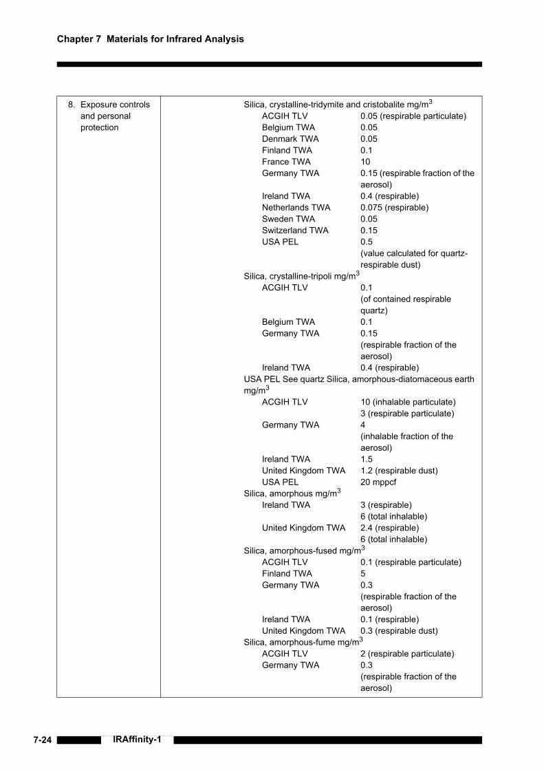
7-24 IRAffinity-1
Chapter 7 Materials for Infrared Analysis
8. Exposure controls and personal protection
Silica, crystalline-tridymite and cristobalite mg/m3
ACGIH TLV 0.05 (respirable particulate)Belgium TWA 0.05Denmark TWA 0.05Finland TWA 0.1France TWA 10Germany TWA 0.15 (respirable fraction of the
aerosol)Ireland TWA 0.4 (respirable)Netherlands TWA 0.075 (respirable)Sweden TWA 0.05Switzerland TWA 0.15USA PEL 0.5
(value calculated for quartz-respirable dust)
Silica, crystalline-tripoli mg/m3
ACGIH TLV 0.1(of contained respirable quartz)
Belgium TWA 0.1Germany TWA 0.15
(respirable fraction of the aerosol)
Ireland TWA 0.4 (respirable)USA PEL See quartz Silica, amorphous-diatomaceous earth mg/m3
ACGIH TLV 10 (inhalable particulate)3 (respirable particulate)
Germany TWA 4 (inhalable fraction of the aerosol)
Ireland TWA 1.5United Kingdom TWA 1.2 (respirable dust)USA PEL 20 mppcf
Silica, amorphous mg/m3
Ireland TWA 3 (respirable)6 (total inhalable)
United Kingdom TWA 2.4 (respirable)6 (total inhalable)
Silica, amorphous-fused mg/m3
ACGIH TLV 0.1 (respirable particulate)Finland TWA 5Germany TWA 0.3
(respirable fraction of the aerosol)
Ireland TWA 0.1 (respirable)United Kingdom TWA 0.3 (respirable dust)
Silica, amorphous-fume mg/m3
ACGIH TLV 2 (respirable particulate)Germany TWA 0.3
(respirable fraction of the aerosol)

7.4 Material Safety Data Sheet
7-25IRAffinity-1
8. Exposure controls and personal protection
Silica, amorphous-precipitated and gel mg/m3
ACGIH TLV 10 (inhalable particulate)Germany TWA 4
(inhalable fraction of the aerosol)
USA PEL 20 mppcfAdditional information:
No dataPersonal protective equipmentGeneral protective and hygienic measures
The usual precautionary measures should be adhered to in handling the chemicals.Keep away from foodstuffs, beverages and food.Instantly remove any soiled and impregnated garments.Wash hands during breaks and at the end of the work.Store protective clothing separately.
Breathing equipment:Use breathing protection with high concentrations.
Eye protection: Safety glassesBody protection: Protective work clothing.
9. Physical and chemical properties:
General InformationForm: PowderColour: WhiteSmell: Odourless
Change in conditionMelting point/Melting range: 1610-1728 °CBoiling point/Boiling range: 2230 °CSublimation temperature / start: Not determined
Flash point: Not applicableIgnition temperature: Not determinedDecomposition temperature: Not determinedDanger of explosion: Product is not explosive.Critical values for explosion:
Lower: Not determinedUpper: Not determined
Steam pressure: Not determinedDensity at 20 °C 2.17-2.66 g/cm3
Solubility in / Miscibility with Water: Insoluble
10. Stability and reactivity
Thermal decomposition / conditions to be avoided:No decomposition if used and stored according to specifications.
Materials to be avoided:InterhalogensHalogensOxidizing agents
Dangerous reactions:Reacts violently with interhalogens.
Dangerous products of decomposition:No dangerous decomposition products known

7-26 IRAffinity-1
Chapter 7 Materials for Infrared Analysis
11. Toxicological information
Acute toxicity:Primary irritant effect:on the skin: Irritant for skin and mucous membranes.on the eye: Irritant effect.Sensitization: No sensitizing effect known.Other information (about experimental toxicology):
Tumorigenic effects have been observed on tests with laboratory animals.Reproductive effects have been observed on tests with laboratory animals.Carcinogenic effects have been observed on tests with laboratory animals.
Additional toxicological information:To the best of our knowledge the acute and chronic toxicity of this substance is not fully known.The Registry of Toxic Effects of Chemical Substances (RTECS) contains tumorigenic and/or carcinogenic and/or neoplastic data for this product.IARC-1: Carcinogenic to humans: sufficient evidence of carcinogenicity.NTP-2: Reasonably anticipated to be a carcinogen: limited evidence from studies in humans or sufficient evidence from studies in experimental animals.
12. Ecological information
General notes: Generally not hazardous for water.Do not allow material to be released to the environment without proper governmental permits.
13. Disposal considerations
Product:Recommendation
Consult state, local or national regulations for proper disposal.Hand over to disposers of hazardous waste.Must be specially treated under adherence to official regulations.
Uncleaned packagings:Recommendation
Disposal must be made according to official regulations.
14. Transport information
Land transport ADR/RID and GGVS/GGVE (cross-border/domestic)ADR/RID-GGVS/E Class: None
Maritime transport IMDG/GGVSea:ADR/RID-GGVS/E Class: None
Air transport ICAO-TI and IATA-DGR:ADR/RID-GGVS/E Class: None
Transport/Additional information:Not dangerous according to the above specifications.

7.4 Material Safety Data Sheet
7-27IRAffinity-1
15. Regulatory information
Designation according to EC guidelines:Code letter and hazard designation of product:
Xn Harmful
Risk phrases: 20 Harmful by inhalation.37 Irritating to respiratory system.
Safety phrases: 9 Keep container in a well-ventilated place.36 Wear suitable protective clothing.
National regulationsInformation about limitation of use:
Employment restrictions concerning young persons must be observed.For use only by technically qualified individuals.
Water hazard class:Generally not hazardous for water.
16. Other information Employers should use this information only as a supplement to other information gathered by them, and should make independent judgment of suitability of this information to ensure proper use and protect the health and safety of employees. This information is furnished without warranty, and any use of the product not in conformance with this Material Safety Data Sheet, or in combination with any other product or process, is the responsibility of the user.

Chapter 7 Materials for Infrared Analysis
7-28
This page is intentionally left blank.
IRAffinity-1

1IRAffinity-1
Index
AA/D error .................................................... 1-12, 4-4AC inlet ..............................................................1-10Accessory ..........................................................5-15Accessory Recognition ........................................4-6accessory recognition terminal ..........................1-11Administrator .....................................................3-14Alternation Check Program ...............................3-11aperture ....................................1-2, 1-12, 4-4, 4-11Apodization ..........................................................1-5apodization function ............................................1-5ASC .....................................................................4-8ASC-8000T ................................................ 4-8, 4-11ASC-A ...............................................................5-15ASTM ..................................................................5-6Atmosphere Correction .......................................4-5ATR-8200HA .....................................................4-11auto sample changer ................................. 1-11, 4-8Auto Sample Switcher ............................... 4-8, 4-11Auto Sampler .......................................................4-8Auto Setting .........................................................4-6
Bbeam splitter ...............................1-2, 1-13, 2-2, 7-5Bessel ..................................................................1-6Box Car ...............................................................1-6Brownout .............................................................5-8
Ccassette ......................................... 1-10, 4-11, 5-18Class 1 .................................................................. xicollimator mirror ...................................................1-2Compensator .......................................................7-5Continuous Scan .................................................4-5
Ddetector ....................................1-12, 2-2, 5-18, 7-5DLATGS detector ..............................................1-13DRS-8010ASC ....................................................4-8dry indicator ..............................1-9, 1-13, 5-2, 5-10dry unit ..................................................... 1-13, 5-18DuraSamplIR IIA ...............................................4-11
EEasy Scan ........................................................... 4-5Emergency ........................................................ 4-12Environment ...................................................... 3-13error message table ............................................ 6-2European Pharmacopoeia .................................. 5-6external beam outlet cover .................................. 1-9
FFile ...................................................................... 6-2fixed mirror .................................................1-2, 1-12Fourier transform ................................................ 1-2fuse ............................................................5-18, 6-9
GGe ................................................................7-2, 7-4GLP mode ......................................................... 3-10
Hhalide ............................................................. iv, 6-7Happ ................................................................... 1-6Happ-Genzel ....................................................... 1-6He-Ne laser ......................................................... 1-7Help ................................................................... 3-10Humidity ...........................................2-4, 5-11, 5-14hypoxia .......................................................... vii, 3-4
IINIT SUCCESS ................................................... 4-3installing the software ......................................... 3-6Instrument Preferences ..................................... 3-13Interference ......................................................... 1-3interferogram .............................. 1-2, 1-3, 1-5, 1-12interferometer .................................................... 1-12IRsolution .......................................................... 5-18
JJapanese Pharmacopoeia .................................. 5-6

2 IRAffinity-1
KKBr ..............................................7-2, 7-3, 7-5, 7-18KBr (potassium bromide) ...................................1-13KRS-5 ...........................................7-2, 7-3, 7-5, 7-6
LLamp ..................................................................5-14Laser ......................................... xi, 5-11, 5-14, 5-18Layout .......................................................... 1-8, 3-4light source .....................1-3, 1-12, 2-2, 5-11, 5-18Liquid Cell ..........................................................4-11
MMCT ...................................................................1-13Michelson interferometer .....................................1-2MIRacle A ..........................................................4-11Mirror speed ...................................... 1-12, 2-2, 4-4moving mirror ............................................. 1-2, 1-12
NNaCl ............................................................. 7-2, 7-3None ....................................................................1-6None of the available background matches the sample parameters ..............................................6-2
Ooptical path difference .........................................1-3optical systems ....................................................1-2optional connector .............................................1-10Oxygen Indicator .................................................3-4Oxygen Shortage ...................................................vii
PPassword ...........................................................3-14Pellet ..................................................................4-11Periodic inspection ...................................... 5-2, 5-6phase ...................................................................1-3Polystyrene ........................................................5-18power indicator .......................................... 1-9, 5-10Power spectrum ........................................... 5-2, 5-4power switch ...................................... 1-9, 4-2, 4-12purge ......................................................... 1-10, 3-4
QQuickStart ........................................................... 4-6
Rresolution ............................................1-12, 2-2, 4-4
SS/N ratio .............................................1-7, 1-16, 2-2sample compartment cover ................................. 1-9sample compartment lid ...................................... 1-9Sample Holder .................................................. 4-11Security ............................................................. 3-14self-diagnosis .................................................... 5-11silica gel ..................1-13, 5-2, 5-3, 5-9, 5-18, 7-22Spectrum ............................................................. 4-5Sqr. Triaug .......................................................... 1-6Start-up inspection .............................................. 5-2status monitor .................................................... 5-14Support for hardlock protected libraries ............ 3-10SW .................................................................... 5-14
TTemperature ........................................................ 2-4top cover ............................................................. 1-9Triang .................................................................. 1-6troubleshooting .................................................... 6-1
UUSB connector .................................................... 1-9User ID .............................................................. 3-14user management ............................................. 3-14Utility ................................................................... 2-4
VValidation program .............................................. 5-6voltage selector switch ........................................ 6-9
WWarning Labels ......................................................ixwavenumber range ........................................... 1-13WEEE .................................................................. xviiWeight ................................................................. 2-2Window ............................................................... 7-5

3IRAffinity-1
ZZnSe ............................................................ 7-2, 7-4

4
This page is intentionally left blank.
IRAffinity-1
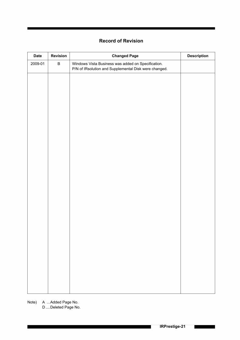
IRPrestige-21
Record of Revision
Note) A ...Added Page No.D ....Deleted Page No.
Date Revision Changed Page Description
2009-01 B Windows Vista Business was added on Specification.P/N of IRsolution and Supplemental Disk were changed.

This page is intentionally left blank.
IRPrestige-21