Embed Size (px)
Citation preview

Pyrheliometer
MS-56
Version 4
INSTRUCTION MANUAL

EKO INSTRUMENTS CO., LTD. MS-56 Pyrheliometer Manual Ver.4
Pg. 1
1. Index
1. Index 1
2. Important User Information 2
2-1. Contact Information 2
2-2. Warranty and L iabi l i t y 2
2-3. About Operat ing Manual 3
2-4. Environment 3
2-5. CE Declarat ion 4
3. Safety Information 5
3-1. General Warnings 5
4. Introduction 6
4-1. Introduct ion 6
4-2. Content of Del ivery 7
5. Getting Started 8
5-1. Parts Descr ipt ions 8
5-2. Setup 9
5-3. Operat ion 14
6. Maintenance & Troubleshooting 15
6-1. Maintenance 15
6-2. Cal ibrat ion and Measurement Uncerta inty 17
6-3. Troubleshoot ing 18
7. Specification 19
7-1. Spec if icat ions 19
7-2. Spec if icat ion Def in it ions 20
7-3. Product Accessor ies 22
APPENDIX 23
A-1. Symbols 23
A-2. Thermistor Temperature Convers ion Table 24
A-3. Pt100 Class A Convers ion Table 25

EKO INSTRUMENTS CO., LTD. MS-56 Pyrheliometer Manual Ver.4
Pg. 2
2. Important User Information
Thank you for using EKO Products.
Reading this manual is recommended prior to installation and operation of the product. Keep this
manual in safe and handy place for whenever it is needed.
For any questions, please contact us at below:
2-1. Contact Information
EKO INSTRUMENTS CO., LTD.
Asia, Oceania Region
www.eko.co.jp
EKO INSTRUMETNS Co., Ltd.
1-21-8 Hatagaya, Shibuya-ku
Tokyo, 151-0072 Japan
Tel: +81 (3) 3469-6713
Fax: +81 (3) 3469-6719
Europe, Middle East, Africa Region
www.eko-eu.com
EKO INSTRUMENTS Europe B.V.
Lulofsstraat 55, Unit 32,
2521 AL, Den Haag, The Netherlands
Tel: +31 (0)70 3050117
Fax: +31 (0)70 3840607
North & South America Region
www.eko-usa.com
EKO INSTRUMENTS USA Inc.
95 South Market Street, Suite 300
San Jose, CA 95113 USA
Tel: +1 408-977-7751
Fax: +1 408-977-7741
2-2. Warranty and Liabi l i ty
For warranty terms and conditions, please contact EKO Instruments or your distributer for further details.
EKO guarantees that the product delivered to customer has been tested to ensure the instrument meets its
published specifications. The warranty included in the conditions of delivery is valid only if the product has
been installed and used according to the instructions provided in this operating manual.
In case any manufacturing defect(s) will occur, the defected part(s) will be repaired or replaced under
warranty; however the warranty will not be applicable if:
Any modification or repair has been done by other than EKO service personnel.
The damage or defect is caused by disrespecting the specifications mentioned on the product
brochure or instruction manual.

EKO INSTRUMENTS CO., LTD. MS-56 Pyrheliometer Manual Ver.4
Pg. 3
2-3. About Operat ing Manual
Copy Rights Reserved by EKO INSTRUMENTS CO., LTD. Making copies of whole or part of this document
without permission from EKO is prohibited.
This manual was issued: 2015/05/22
Version Number: 4
2-4. Envi ronment
1. WEEE Directive 2002/96/EC (Waste Electrical and Electronic Equipment)
This product is not subjected to WEEE Directive 2002/96/EC however it should not be mixed with general
household waste. For proper treatment, recovery and recycling, please take this product(s) to designated
collection points.
Disposing of this product correctly will help save valuable resources and prevent any potential negative effects
on human health and the environment, which could otherwise arise from inappropriate waste handling.
2. RoHS Directive 2002/95/EC EKO Instruments has completed a comprehensive evaluation of its product range to ensure compliance with
RoHS Directive 2002/95/EC regarding maximum concentration values for substances. As a result all products
are manufactured using raw materials that do not contain any of the restricted substances referred to in the
RoHS Directive 2002/95/EC at concentration levels in excess of those permitted under the RoHS Directive
2002/95/EC, or up to levels allowed in excess of these concentrations by the Annex to the RoHS Directive
2002/95/EC.

EKO INSTRUMENTS CO., LTD. MS-56 Pyrheliometer Manual Ver.4
Pg. 4
DECLARATION OF CONFORMITY
We: EKO INSTRUMENTS CO., LTD
1-21-8 Hatagaya, Shibuya-ku
Tokyo, 151-0072 JAPAN
Declare under our sole responsibility that the product:
Product Name: Pyrheliometer
Model No.: MS-56
To which this declaration relates is in conformity with the following harmonized
standards of other normative documents:
Harmonized standards:
EN 61326-1:2006 Class A (Emission)
EN 61326-1:2006 (Immunity)
EN 61000-4-2 EN 61000-4-3
EN 61000-4-4 EN 61000-4-5
EN 61000-4-6 EN 61000-4-8
EN 61000-4-11
Following the provisions of the directive:
EMC-directive: 89/336/EEC
Amendment to the above directive: 93/68/EEC
Date: April 28, 2011
Position of Authorized Signatory: Deputy General Manager of Quality Assurance Dept.
Name of Authorized Signatory: Shuji Yoshida
Signature of Authorized Signatory:
2-5. CE Declarat ion

EKO INSTRUMENTS CO., LTD. MS-56 Pyrheliometer Manual Ver.4
Pg. 5
3. Safety Information
EKO Products are designed and manufactured with consideration for safety; however, please make
sure to read and understand this instruction manual thoroughly to be able to operate the instrument
safely in the correct manner.
WARNING CAUTION
Attention to user; pay attention to the instructions given on the
instruction manual with this sign.
3-1. General Warnings
Setup When applying the window heating the power consumption at 12 VDC is approximately 0.5 W. Check your
DC output Voltage before operating, higher voltages will lead to permanent damage of the heater.

EKO INSTRUMENTS CO., LTD. MS-56 Pyrheliometer Manual Ver.4
Pg. 6
4. Introduction
4-1. Introduct ion
The ISO9060 First Class MS-56 is a research grade normal incidence direct solar irradiance sensor also
known as a pyrheliometer or DNI sensor which highly suitable for routine operation on automated Sun Tracker.
The all-weather MS-56 is sensitive to solar irradiance throughout the spectral range 200 to 4,000nm and can
work under most extreme conditions in a temperature range from -40°C to +80°C.
In principle to perform high precision direct solar radiation measurements under non-stable atmospheric
conditions, ideally a fast responding detector is required to detect quick radiation changes. Although
photodiode type detector offer a quick response but it has a limited spectral sensitive range; in contrary
thermopile broad band detectors cover the full spectral range, but it is considered to be slow. The versatile
MS-56 combines all those features of a quick broadband detector enabled by an advanced technology
thermopile detector. It combines a unique fast response time (<1s 95%), high sensitivity, excellent thermal
stability and very low temperature coefficient to make it hardly immune to ambient temperature variations,
therefore it is suitable to be used in a wide temperature range.
The MS-56 has a standard full 5° (degrees) opening angle and 1° slope angle as defined by ISO
Pyrheliometers Standards and greatly performs when used in combination with the EKO STR-21(G) or
STR-22(G) Sun Tracker. The standard built-in thermistor (44031, 10kΩ@25) or platinum resistance
temperature sensor (Pt100, Class A, IEC751 compliance) can be used as a temperature reference for
extensive research purposes. The integrated low power window heater prevents dew deposition or frost on
the outside window.
The MS-56 has a robust but compact and smooth design which forms the new generation of EKO Instruments
solar radiometers that are designed for most demanding Photovoltaic and Meteorological applications at any
place on earth.
Each MS-56 is calibrated and tested at EKO upon manufacture against EKO’s reference sensors which are
fully traceable to the WRR (World Radiometric Reference) maintained at the PMOD/WRC
(Physikalisch-Meteorologisches Observatorium Davos/World Radiation Center) in Davos, Switzerland.

EKO INSTRUMENTS CO., LTD. MS-56 Pyrheliometer Manual Ver.4
Pg. 7
4-2. Content of Del ivery
Check the package contents first; if any missing item or damage is noticed, please contact EKO immediately.
Figure 4-1. Package Contents
(Standard Length: 10m)

EKO INSTRUMENTS CO., LTD. MS-56 Pyrheliometer Manual Ver.4
Pg. 8
5. Getting Started
5-1. Parts Descript ions
MS-56 pyrheliometer is designed to capture direct solar radiation with high precision and long term reliability.
The new concept is a result of combining new technologies with proven pyrheliometer basics to fulfill most
stringent demands for solar energy research in the Photovoltaic and Meteorological market.
The Pyrheliometer is based on a well balanced light weight thermopile detector, which gives a highly stable
output under most critical situations and variable measurement conditions. Each detector is individually
characterized and temperature compensated to guarantee its best performance. During field operating, the
detector temperature can be monitored with a thermistor (44301 10kΩ) or platinum resistance temperature
sensor (Class A Pt100) to extend further research applications.
Although the MS-56 dimensions are relatively small, it has a full 5° opening angle and 1° slope angle
geometry. The front aperture has a unique integrated alignment sight for easy and precise alignment of the
instrument on a Sun Tracker. The removable rain cap can be used as a rain shield but can also be taken off
when the measurement conditions allow. In order to attain the proper spectral characteristics and spectral
range, the pyrheliometer has Quartz precision optics and ultra low reflective black detector absorber to
capture direct solar radiation in the specified spectral range.
The large volume desiccant cartridge ensures a dry environment inside the pyrheliometer to protect delicate
optical parts from any condensation. A cable with plug in connector is provided for easy handling and flexibility
during installation, maintenance and service. The basic construction outline is shown in the assembly
drawing.
Figure 5-1. MS-56 Body
4. Baffles
9. Detector Aperture
5. Sensor Body
8. Plug-in Connector
1. Rain Cap
6. Temperature sensor 7. Drying Cartridge
3. Sight
2. Quartz Window with Heater

EKO INSTRUMENTS CO., LTD. MS-56 Pyrheliometer Manual Ver.4
Pg. 9
5-2. Setup
1. Installation In this application the MS-56 is mounted on the EKO Sun Tracker STR-21G/22G, which is a fully automatic
sun tracking system supporting solar sensors capable of measuring Direct, Diffuse and Global radiation.
1) When mounting the MS-56, use the fixing hole in
the middle of the mounting plate.
*If the mounting plate is the 2-hole version, it is
necessary to replace with 3-hole version. (See
following [2. How to Replace Mounting Plate
(Optional)])
2) Remove the knurling nut from the MS-56 mounting
screw by hand. (Above picture shows condition the
knurling nut is removed.)
3) Place the MS56 on the Sun Tracker mounting plate.
Insert the mounting screw through the mounting plate
center hole.
4) Attach the knurling nut which was removed earlier
back on the mounting screw; tighten so the MS-56 is
fixed securely.
X/Y-Axis
Adjustment Unit

EKO INSTRUMENTS CO., LTD. MS-56 Pyrheliometer Manual Ver.4
Pg. 10
2. How to Replace the Mounting Plate (Optional)
When installing MS-56 on EKO Sun Tracker STR-21G/22G, 3-hole mounting plate is required.
If you already have EKO Sun Tracker purchased before July 2011, you need to purchase the “3-hole mounting
plate” (optional part) separately for installing MS-56.
If the 3-hole mounting plate is already installed, skip this section and go to [3. Electrical Connection].
「Prepare the following tool for installation」: One Allen Key 2.5 (for M3 screw).
[How to Replace]
(1) Remove the 4 fixing screws (M3 x 15mm) which are securing the X/Y-Axis adjustment unit on the Sun
Tracker Arm (see above image)
*Be careful not to lose the removed screws!
Screws for X/Y-Axis Adjustment Unit
(M3 x 15mm in 4 places)
WARNING: DO NOT TOUCH!!
Do Not loosen these screws!
If these screws are loosen, the Sun Sensor
position may shift and accurate measurement
cannot be taken.
Sun Sensor
Fixing Screws (3 places)
Sun Sensor Holder
Fixing Screws (2 places)
Mounting Plate
Sun Tracker Arm
Sun Tracker Arm Fixing
Screws (4 places)

EKO INSTRUMENTS CO., LTD. MS-56 Pyrheliometer Manual Ver.4
Pg. 11
(2) Lift up the mounting plate as shown on the image above.
(3) As the mounting plate is lifted, remove another 4 fixing screws (M3 x 15mm) on X/Y-Axis adjustment unit then
detach the X/Y-Axis adjustment unit from the mounting plate.
(4) Remove 2 fixing screws (M3 x 15mm) for mounting plate. Detach the mounting plate from the Sun Tracker
Arm, and remove the fixing screws on both V-Blocks (M3 x 5mm in 2 places on each V-Block).
Disassembling is completed and the 2-hole mounting plate is replaced with 3-hole mounting plate.

EKO INSTRUMENTS CO., LTD. MS-56 Pyrheliometer Manual Ver.4
Pg. 12
(5) Attach the V-Blocks on the 3-hole mounting plate with fixing screws (M3 x 5mm in 2 laces for each V-Block)
then attach the 3-hole mounting plate on the Sun Tracker Arm with 2 fixing screws. (M3 x 15mm)
(6) Attach the X/Y-Axis adjustment unit on the 3-hole mounting plate with the fixing screws (M3 x 15mm in 4
places) then attach the X/Y-Axis adjustment unit on the Sun Tracker Arm with the fixing screws (M3 x 15mm in 4
places)
Check to make sure all the screws are placed back in their positions.
3. Electrical Connection In order to measure the solar irradiance, the MS-56 should be connected to a measurement device, in most
cases a data logger. MS-56 is a passive sensor that does not need any power; however to operate the window
heater, a DC12V (0.5W) power supply is required for heating.
It is recommended to keep the cable length between data logger and the sensor as short as possible.
Depending on how the cable is lined, unwanted noise is caused; thus, keep the cable away from the noise
cause, such as AC cable or high voltage line. Also in some cases, more noise is seen depending on the type
of data logger used.
EKO INSTRUMENTS CO., LTD. MS-56 Pyrheliometer Manual Ver.4
Pg. 13
Using a signal converter is recommended when the distance between the pyrheliometer is > 50m. Connect
the cable connector to the MS-56 chassis plug and keep sufficient length to allow free rotation when installed
on a Sun Tracker.
The wire color codes are shown in the table below.
Table 5-1 Wire Color Codes
Color Wires
Brown Sensor output +
Red Sensor output -
Yellow Heater Input (12V DC) +
Green Heater Input (12V DC) -
Blue
PT100 (A) 3-wire Gray
White PT100 (B) 3-wire or Thermistor (B)
Black Thermistor (A)
Yellow / Green
(Stripe Color) Ground (Shield)
Note:
The pyrheliometer housing is connected to the shielded cable (yellow stripe). When the shielded cable is
connected to the data logger ground, the pyrheliometer should be electrically isolated from the sun-tracker
system or the sun tracking system should not be connected to ground.
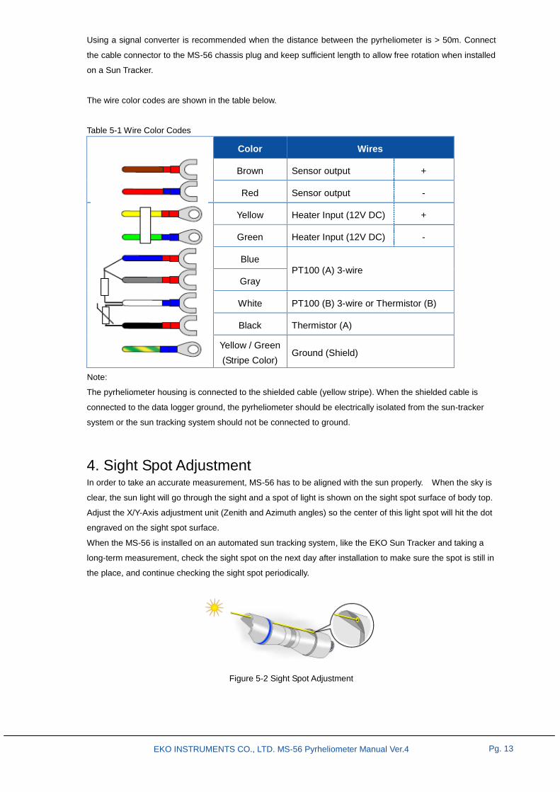
4. Sight Spot Adjustment In order to take an accurate measurement, MS-56 has to be aligned with the sun properly. When the sky is
clear, the sun light will go through the sight and a spot of light is shown on the sight spot surface of body top.
Adjust the X/Y-Axis adjustment unit (Zenith and Azimuth angles) so the center of this light spot will hit the dot
engraved on the sight spot surface.
When the MS-56 is installed on an automated sun tracking system, like the EKO Sun Tracker and taking a
long-term measurement, check the sight spot on the next day after installation to make sure the spot is still in
the place, and continue checking the sight spot periodically.
Figure 5-2 Sight Spot Adjustment

EKO INSTRUMENTS CO., LTD. MS-56 Pyrheliometer Manual Ver.4
Pg. 14
5-3. Operat ion
After installing and connecting MS-56 to the measurement device, MS-56 can be operated and is ready to
collect solar radiation data.
It is recommended to use the window heater to prevent dew deposition at the Quartz window. Turn on the
heater at least 30 minutes before sunrise. After sun rise, the window heater might be switched off to save
energy.
1. Calculate Direct Normal Incidence Solar Irradiance The direct normal incidence solar irradiance is calculated from the measured output voltage according to the
following linear expression.
I [W/m2]: Direct Normal Incidence solar irradiance
E [µV]: Output voltage of the sensor
S [µV/W・m-2
]: Sensitivity (Indicated on the calibration certificate)
2. Calculate Direct Horizontal Incidence Solar Irradiance The direct horizontal incidence solar irradiance is calculated from the measured output voltage according to
the following linear expression.
θ [°]: Solar Elevation Angle
3. Calculate Detector Temperature When a thermistor temperature sensor (44031 10kΩ) is used, the detector temperature T[] can be
converted from resistance R[Ω] by using the following formula. The temperature conversion table is also
shown in Appendix A-2.
[Thermistor (44031 10kΩ)]
α = 1.0295・10-3
β = 2.3910・10-4
γ = 1.5680・10-7
When using a platinum resistance temperature sensor (Pt100, Class A), see the temperature conversion table
shown in Appendix A-3.

EKO INSTRUMENTS CO., LTD. MS-56 Pyrheliometer Manual Ver.4
Pg. 15
6. Maintenance & Troubleshooting
6-1. Maintenance
Once the MS-56 is installed, it is essentially free of any maintenance although care must be taken to keep the
instrument in the best condition for accurate measurement.
1. Data Verification By analyzing the measurement data (such as irradiance and temperature), user can verify the condition of the
instrument. When abnormal data is found, either the sight of the pyrheliometer is not aligned or the instrument
has some defect. Check the condition of cable at the same time checking on the pyrheliometer setup
condition.
2. Cleaning of Quartz Window Clean the quartz window with a soft cotton cloth and alcohol or demineralized water when it gets soiled. Since
soiling will have an effect on the performance of the radiometer by means of reduced optical transmission of
the solar radiation and consequently leads to a reduced detector output. Despite no proper indication can be
given on the required cleaning interval since it is strongly depending on the local environmental conditions
affected by Rain, Snow, Ice, Dust, Sand, or Salt. Environmental factors like frequent rain fall can also have a
positive effect on cleaning by washing off any sand or dust particles. For specific cases it might be an
advantage to remove the Rain Cap and benefit from this effect. The success of this approach can be
determined empirically.
3. Desiccant Inspection Periodically the desiccants need to be exchanged to maintain a dry environment inside the pyrheliometer. The
frequency of replacement varies with the operating conditions on location but annual replacement is
recommended. The section at the next page shows how to replace desiccant.
4. Pyrheliometer Alignment The measurement performance can also be inspected by carefully analyzing the measurement data (e.g.
irradiance and temperature). Any abnormality found in the data might be caused by misalignment of the
sensor or defect. At regular intervals, the quality of the cables can be checked like the alignment of the
pyrheliometer.
5. Clean the Sight Sometimes rain and dirt maybe collected in the through-hole for the sight and the sight spot cannot be
confirmed. Clean and remove the water and/or dirt by using a small diameter pin.
6. Recalibration EKO Instruments recommend to recalibrate the sensor every 2 years.

EKO INSTRUMENTS CO., LTD. MS-56 Pyrheliometer Manual Ver.4
Pg. 16
Table 6-1 Maintenance check List
Check List Action
Data verification Check the wiring connections
Cleaning of Quartz window Use soft cotton cloth and alcohol or demineralized water
Desiccant inspection Change in case the silica gel color turned from blue to
reddish color
Pyrheliometer alignment
Check sights for alignment. When the sight spot cannot
be confirmed, clean the through-hole with a pin to
remove the water and/or dirt.
Recalibration Every 2 years
[How to Replace Desiccant]
1) Turn the drying cartridge in anti-clockwise. No tools
are required.
2) The drying cartridge can be removed easily by hand.
3) Take off the inner lid.
4) Exchange the desiccant then put the inner lid back on
the cartridge. Place the drying cartridge back on the
MS-56 body and secure it gently.

EKO INSTRUMENTS CO., LTD. MS-56 Pyrheliometer Manual Ver.4
Pg. 17
6-2. Cal ibrat ion and Measurement Uncertainty
It is recommended to recalibrate the instrument once every 2 years. For further information about the
calibration and recalibration, please contact EKO.
1. Calibration Method The MS-56 is calibrated under natural sun light against the EKO instruments reference pyrheliometer which is
traceable to the World Radiation Reference (WRR) maintained at the World Radiation Center (PMOD) in
Davos (CH).
Both MS-56 and reference pyrheliometer are mounted on a Sun Tracker to capture the direct solar radiation.
The direct solar radiation is measured based on 1 minute samplings for total of more than 2 hours both in the
morning and the afternoon on a clear day. The calibration value of the subjected pyrheliometer was obtained
by multiplying the sensitivity value [μV/W・m-2
] of the reference pyrheliometer with the averaged ratio of the
measured total direct irradiance data. To improve the calibration accuracy and minimize the measurement
uncertainty several operating criteria are applied.
2. Calibration Uncertainty and Traceability The criteria for the operating conditions like the indicated ambient temperature, minimum direct radiation and
minimum solar elevation angle are applied to minimize the overall uncertainty in the calibration. The
pyrheliometer uncertainty figure is statistically calculated based on a standard deviation of (1.96σ), which
means that 95% of the measured direct irradiance values agree with the reference pyrheliometer.
The reference pyrheliometer will be calibrated at ATLAS/DSET every 2 years against a primary standard
pyrheliometer, called absolute cavity pyrheliometer. The ATLAS/DSET absolute radiometer is directly
traceable to the WRR (World Radiometric Reference) and maintained in the group of standard radiometers
calibrated every 5 years during the IPC (International Pyrheliometer Comparison), as well as by NPC (NREL
Pyrheliometer Comparison) which is held every year.
The data acquisition system is traceable to JEMIC (Japan Electric Meters Inspection Corporation).

EKO INSTRUMENTS CO., LTD. MS-56 Pyrheliometer Manual Ver.4
Pg. 18
6-3. Troubleshoot ing
This section contains information that can be used to make a failure diagnosis whenever the sensor does not
function properly. Contact your distributor or EKO for any further technical support.
Table 6-3 Troubleshooting
Potential failure Action
The sensor does not give
any signal output
1. Measure the impedance across the sensor output wires. This sensor
resistance should lie in the specified range (see 7.1 Specifications). If
it is close to zero Ohms there is a short circuit (check the wiring). If it is
infinite, there is a broken contact (check the wiring).
2. If no problem found from the above, check the output with another
measurement device to make sure the actual data logger or
measurement device is functioning properly.
The sensor signal is
unrealistically high or low.
1. Check if the correct sensitivity is applied to the algorithm (see 5-3.
Operation). Please note that each sensor has its own individual
sensitivity. Check if the voltage reading is divided by the correct
sensitivity value.
2. Check the sight spot and make sure the MS-56 is aligned to the
direction of the sun.
The sensor signal shows
unexpected variations.
Although the sensor is hardly susceptible to Electro Magnetic
Interference (IME), it may pick up noise depending on the measuring
environment.
1. Check the presence of strong EM sources of radar, radio, etc..
2. Check the grounding condition (shielding). Check the condition of the
sensor cable.

EKO INSTRUMENTS CO., LTD. MS-56 Pyrheliometer Manual Ver.4
Pg. 19
7. Specification
7-1. Speci f icat ions
Table 7-1 Specification: Specifications are indicated as typical values.
Specification MS-56 ISO 9060
First Class
WMO
Good Quality
Response time (95%) < 1 s < 20s < 30s
Non-Linearity (100 – 1000 W/m2) < +/- 0.5 % < +/-0.5% < +/- 0.5 %
Zero Offset (response to 5 K/h change in
ambient temperature) < +/- 1 W/m
2 < +/- 3 W/m
2 < 4 W/m
2
Spectral Selectivity
(350 to 1500 nm ISO
/3000 nm WMO
) < +/- 1 % < +/- 1 % 1 %
Tilt response < +/- 0.2 % < +/- 0.5 % 0.5 %
Temperature Dependency
(-20 to + 50°C / @ 20°C) < +/- 0.5 %
< +/- 2 %
( For 50 band)
< 2%
( For 50 band)
Non Stability (Change per year) < +/- 0.5 % < +/- 1 % < +/- 0.5 %
Expected Daily Uncertainty < +/- 1 % - - - < +/- 1 %
Irradiance Range 0 –2000W/m2 - - - - - -
Spectral Range (FWHM) 200 –4000nm - - - - - -
Sensitivity Approx.10μV/W・m-2
- - - - - -
Detector Impedance @ 25°C Approx.5 kOhms - - - - - -
Operating Temperature -40 to +80 °C - - - - - -
Ingress Protection Rating IP 67 - - - - - -
Low Voltage Regulations IEC 61326-1-2006 - - - - - -
Compliance CE Compliant - - - - - -
Outer Dimensions (Length x Diameter) 217mm x 55mm - - - - - -
Cable Length (Standard) 10 m - - - - - -
Weight (Including 10m cable) 0.6kg (1.6 kg) - - - - - -
Heater power for optional window heater
to prevent dew deposition DC12V / 0.5W - - - - - -
Calibration Traceability (ISO 9847) WRR - - - - - -
Recommended Recalibration Interval Every 2 years - - - - - -
Sensor for Temperature Measurement
(Internal Temperature Measurement)
- Pt100 Class A,
IEC751 Compliance
- Thermister 44031,
10kΩ@25
- - - - - -

EKO INSTRUMENTS CO., LTD. MS-56 Pyrheliometer Manual Ver.4
Pg. 20
Figure 7-1. MS-56 Outer Dimensions
7-2. Speci f icat ion Def ini t ions
1. Response Time (Typical) A response time of less than 1s to achieve 95% of the final measurement value is one of the unique features
of the MS-56. The small thermopile detector having a low heat capacitance and high thermal conductivity
responds quickly to changes of the solar radiation. To keep the detector-output stable and in perfect thermal
balance during changing environmental and solar radiation conditions, the detector body is isolated from the
sensor housing. When using a data logger with a sampling frequency of 1second, because of the fast
responding detector the measurement data are stored without losses of the natural radiation changes.
Figure 7-1. Response Time Measurement
EKO INSTRUMENTS CO., LTD. MS-56 Pyrheliometer Manual Ver.4
Pg. 21
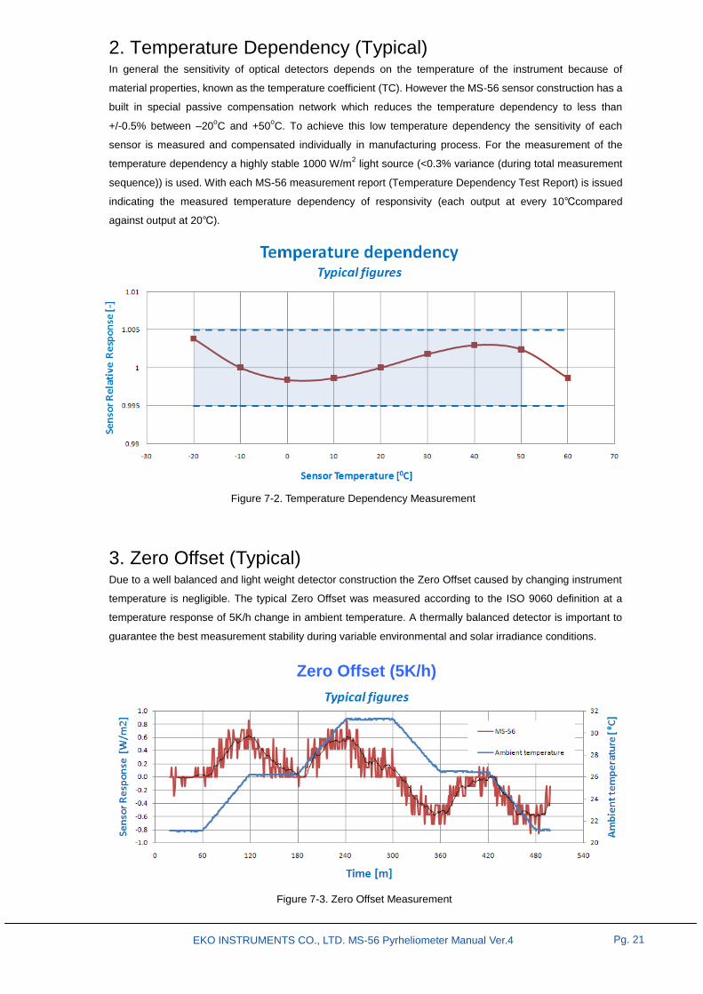
2. Temperature Dependency (Typical) In general the sensitivity of optical detectors depends on the temperature of the instrument because of
material properties, known as the temperature coefficient (TC). However the MS-56 sensor construction has a
built in special passive compensation network which reduces the temperature dependency to less than
+/-0.5% between –20oC and +50
oC. To achieve this low temperature dependency the sensitivity of each
sensor is measured and compensated individually in manufacturing process. For the measurement of the
temperature dependency a highly stable 1000 W/m2 light source (<0.3% variance (during total measurement
sequence)) is used. With each MS-56 measurement report (Temperature Dependency Test Report) is issued
indicating the measured temperature dependency of responsivity (each output at every 10compared
against output at 20).
3. Zero Offset (Typical) Due to a well balanced and light weight detector construction the Zero Offset caused by changing instrument
temperature is negligible. The typical Zero Offset was measured according to the ISO 9060 definition at a
temperature response of 5K/h change in ambient temperature. A thermally balanced detector is important to
guarantee the best measurement stability during variable environmental and solar irradiance conditions.
Figure 7-2. Temperature Dependency Measurement
Figure 7-3. Zero Offset Measurement
Zero Offset (5K/h)

EKO INSTRUMENTS CO., LTD. MS-56 Pyrheliometer Manual Ver.4
Pg. 22
7-3. Product Accessories
Table 7-2 Accessories List
Accessories Details
Cable Length* 20, 30, 40, 50m
STR-21/22 Mounting Jigs
Fixing Ring
Mounting Plate (3-holes)
Drying Cartridge Drying Cartridge
Replacement Silica Gel Replacement Silica Gel (desiccant) container (500g)
*Standard cable length: 10m

EKO INSTRUMENTS CO., LTD. MS-56 Pyrheliometer Manual Ver.4
Pg. 23
APPENDIX
A-1. Symbols
Table A-1 Definitions of Symbols
List of symbols Definitions Units
E Output Voltage μV
S Sensitivity μV/W・m-2
t Time s
τ Response Time s
T Temperature °C
I Solar Irradiance W/m2

EKO INSTRUMENTS CO., LTD. MS-56 Pyrheliometer Manual Ver.4
Pg. 24
A-2. Thermistor Temperature Conversion Table
Table A-2 Temperature Conversion table for the Thermistor (44031, 10kΩ@25)
T [°C] R [Ω] T [°C] R [Ω] T [°C] R [Ω]
-30
-29
-28
-27
-26
-25
-24
-23
-22
-21
-20
-19
-18
-17
-16
-15
-14
-13
-12
-11
-10
-9
-8
-7
-6
-5
-4
-3
-2
-1
135200
127900
121100
114600
108600
102900
97490
92430
87660
83160
78910
74910
71130
67570
64200
61020
58010
55170
52480
49940
47540
45270
43110
41070
39140
37310
35570
33930
32370
30890
0
1
2
3
4
5
6
7
8
9
10
11
12
13
14
15
16
17
18
19
20
21
22
23
24
25
26
27
28
29
29490
28150
26890
25690
24550
23460
22430
21450
20520
19630
18790
17980
17220
16490
15790
15130
14500
13900
13330
12790
12260
11770
11290
10840
10410
10000
9605
9227
8867
8523
30
31
32
33
34
35
36
37
38
39
40
41
42
43
44
45
46
47
48
49
50
51
52
53
54
55
56
57
58
59
8194
7880
7579
7291
7016
6752
6500
6258
6026
5805
5592
5389
5193
5006
4827
4655
4489
4331
4179
4033
3893
3758
3629
3504
3385
3270
3160
3054
2952
2854

EKO INSTRUMENTS CO., LTD. MS-56 Pyrheliometer Manual Ver.4
Pg. 25
A-3. Pt100 Class A Conversion Table
Table A-3 Conversion Table for Pt100 Class A (complying with JIS C 1604 1997)
T [°C] R [Ω] T [°C] R [Ω] T [°C] R [Ω]
-30
-29
-28
-27
-26
-25
-24
-23
-22
-21
-20
-19
-18
-17
-16
-15
-14
-13
-12
-11
-10
-9
-8
-7
-6
-5
-4
-3
-2
-1
88.2
88.6
89.0
89.4
89.8
90.2
90.6
91.0
91.4
91.8
92.2
92.6
92.9
93.3
93.7
94.1
94.5
94.9
95.3
95.7
96.1
96.5
96.9
97.3
97.7
98.0
98.4
98.8
99.2
99.6
0
1
2
3
4
5
6
7
8
9
10
11
12
13
14
15
16
17
18
19
20
21
22
23
24
25
26
27
28
29
100.0
100.4
100.8
101.2
101.6
102.0
102.3
102.7
103.1
103.5
103.9
104.3
104.7
105.1
105.5
105.8
106.2
106.6
107.0
107.4
107.8
108.2
108.6
109.0
109.3
109.7
110.1
110.5
110.9
111.3
30
31
32
33
34
35
36
37
38
39
40
41
42
43
44
45
46
47
48
49
50
51
52
53
54
55
56
57
58
59
111.7
112.1
112.4
112.8
113.2
113.6
114.0
114.4
114.8
115.2
115.5
115.9
116.3
116.7
117.1
117.5
117.9
118.2
118.6
119.0
119.4
119.8
120.2
120.6
120.9
121.3
121.7
122.1
122.5
122.9

EKO INSTRUMENTS CO., LTD. MS-56 Pyrheliometer Manual Ver.4
Pg. 26
Japan: www.eko.co.jp
Europe: www.eko-eu.com
USA: www.eko-usa.com