Embed Size (px)
Citation preview

MULTI-COOL® LOW TEMPERATURE BATH / CIRCULATOR
MNL-006-A REV. 005
INSTRUCTION MANUAL
FTS ▪ 3538 MAIN STREET, STONE RIDGE NY 12484 ▪ WWW.SPINDUSTRIES.COM ▪ 845-687-0071 ▪ [email protected]

© 2008 SP Industries, Inc. All Rights Reserved
FTS ▪ Thermal Division ▪ 3538 Main Street ▪ POB 158 ▪ Stone Ridge, NY 12484 ▪ USA 800.824.0400 ▪ Phone: 845.687.0071 ▪ Fax: 845.687.7481 ▪ [email protected]
www.SPindustries.com
SP Industries Corporate Headquarters: 935 Mearns Road ▪ Warminster, PA 18974 ▪ USA ▪ 800.523.2327 ▪ Phone: 215.672.7807 Fax: 215.672.7807

FTS STONE RIDGE, NEW YORK USA 800.824-0400
III
Table of Contents Introduction and General Description of the Systems............................................................................5 Installation and Operation.......................................................................................................................6
Unpacking ..........................................................................................................................................6 Inspection ...........................................................................................................................................6 Air Flow Considerations .....................................................................................................................6 Electrical Connection, No Control Units .............................................................................................6 Magnetic Stirrer ..................................................................................................................................6 Fluid Filling .........................................................................................................................................7 Refrigeration.......................................................................................................................................7 Initial Cooling......................................................................................................................................7
Maintenance ...........................................................................................................................................8 Fluids .................................................................................................................................................10 Multi-Cool Stirrer Control ......................................................................................................................12
Operation..........................................................................................................................................12 Microprocessor Multi-Cool Operating Instructions ...............................................................................14
Overview ..........................................................................................................................................14 4-Digit Display Interpretation............................................................................................................15 LED Interpretation ............................................................................................................................16 System Considerations ....................................................................................................................17
RS232 EDC Basic Digital Control Instructions .....................................................................................19 Overview ..........................................................................................................................................19 Control Buttons.................................................................................................................................21 Parameter Settings...........................................................................................................................22 System Parameter Definition / Set-Up .............................................................................................23 Error Messages ................................................................................................................................26 Calibration ........................................................................................................................................28
RS232 Programmer Instructions ..........................................................................................................29 Overview ..........................................................................................................................................29 Hardware..........................................................................................................................................29 Communications...............................................................................................................................29 Alarm Codes.....................................................................................................................................40 RS232 Error Codes..........................................................................................................................41 Sample Program ..............................................................................................................................43
FTS Service and Warranties ................................................................................................................44 Service Contact ................................................................................................................................44 Service Agreement...........................................................................................................................44 Standard Warranty ...........................................................................................................................45 Service Options ................................................................................................................................46 Return of FTS Equipment ................................................................................................................47
Accessories ..........................................................................................................................................48

FTS STONE RIDGE, NEW YORK USA 800.824-0400
IV

MULTI-COOL THERMAL MNL-006-A DIVISION REV. 005
FTS STONE RIDGE, NEW YORK USA 800.824-0400
5
INTRODUCTION AND GENERAL DESCRIPTION OF THE SYSTEMS
The Multi-Cool System utilizes small compressors and ultra-low temperature refrigerants, combined with a unique evaporator-cabinet configuration to give maximum refrigeration capacity in a reliable compact package. The systems are available in 4-liter and 8-liter sizes and a low temperature of -80°C. The model number indicates the size bath and low temperature obtainable by the system (e.g. MC880 indicates that the unit has an 8-liter fluid capacity and is capable of obtaining -80°C). The systems can be used not only as a storage chamber or cooling bath, but with the proper accessories as a circulating bath or cold plate. Please see your Multi-Cool bulletin for details on these accessories. The stainless steel chamber is refrigerated by direct expansion of refrigerant and insulated with polyurethane foam, the most efficient insulation currently available. A unique arrangement of the refrigeration condenser permits efficient air cooling in a minimum of space.

MULTI-COOL THERMAL MNL-006-A DIVISION REV. 005
FTS STONE RIDGE, NEW YORK USA 800.824-0400
6
INSTALLATION AND OPERATION
UNPACKING In addition to the bath itself, there is:
• a Magnetic Stirrer Assembly • a Bath Lid Assembly
INSPECTION Make a visual check of the system to check for shipping damage. Concealed Damage can occur even if the crate or carton is not damaged. If the crate or carton is dropped it may not harm the package, but the shock can cause breakage. This is the responsibility of the transportation company and a report must be made to the transportation company for Concealed Damage. A request for inspection must be registered with the transportation company. All packaging material must be kept for inspection. FTS carefully tests all products thoroughly for quality and operational specifications, then packs the instrument with more than adequate packing material to insure that an operational instrument will arrive.
AIR FLOW CONSIDERATIONS The system is shipped ready to operate. Place the unit in a working area with at least 6” of clearance on each side of the unit. The refrigeration system is air cooled. On cascade systems (MC480 and MC880) air is pulled from the front and bottom of the unit, and exits the rear.
NOTE: Blocking the air flow will damage the refrigeration system. For best low temperature operation, the unit should be operated in a normal ambient temperature of 22°C (72°F). Higher ambient temperatures will not permit the unit to reach its ultimate low temperature.
NOTE: Do not operate the systems in ambient temperatures above 32°C (90°F).
ELECTRICAL CONNECTION, NO CONTROL UNITS Check to see that the refrigeration switch is in the OFF (down) position and plug the line cord into a wall receptacle of the appropriate voltage. The power requirements of the system are listed on a tag near the line cord.
MAGNETIC STIRRER Remove the magnet keepers from the bottom of the bath and the bottom of the magnetic stirrer. Place the magnetic stirrer in the bottom of the bath and adjust the holding screws so the stirrer assembly fits snugly and centered within the bath. Press the “Power” button. The magnetic stirrer will rotate. The speed can be adjusted by turning the control knob counter clockwise. If the magnetic stirrer does not rotate, turn the unit off, UNPLUG the unit, and remove the cover. The driving magnet for the stirrer is located under the bath and is driven by a belt attached to a motor. Check to see that the belt has a slight tension on it. If the unit was knocked around during shipping this belt may have

MULTI-COOL THERMAL MNL-006-A DIVISION REV. 005
FTS STONE RIDGE, NEW YORK USA 800.824-0400
7
become too tight or too loose. You can adjust the tightness of the belt by loosening the motor mounting nuts, sliding the motor in the appropriate direction, and retightening the mounting nuts. The drive belt is a toothed belt and does NOT rely on tension for operation. There should be at least ¼” of play when pressing on the belt.
FLUID FILLING Fill the system with a fluid appropriate for the temperature range that you will be operating the system at. See page 10 for a list of some possible fluids and their properties. Fill the bath to about ½” below the gasket at its HIGHEST operating temperature. If the bath is heated after filling, the fluid may expand and leak out the top of the system. CAUTION: Fluids contract when cooled and expand when heated. If you add fluid while the system is at a sub-ambient temperature, and fail to drain fluid before returning to room temperature, the fluid will expand and overfill the chamber. The gasket at the top of the chamber does not provide a liquid tight seal. Consequently, if the chamber is overfilled, the liquid will flow over the chamber rim into the polyurethane insulation. ORGANIC SOLVENT WILL ATTACK THE POYURETHANE INSULATION. The insulation is then dissolved or made ineffective as an insulator. When the insulation is saturated with solvent, the Multi-Cool will no longer reach maximum low temperature or achieve the specified pull-down rate. When the system has been filled with fluid, turn on the magnetic stirrer.
NOTE: The magnetic stirrer must be on for the system to work properly.
REFRIGERATION Within three minutes, the “Cool” LED will light (see “Cool LED”). Listen for the low hum of the fan. If it appears that the fan is not operating, turn the unit OFF, UNPLUG the unit, remove the wrapper, and determine if any obstruction is preventing the fan from rotating. If the fan rubs, usually a slight adjustment will correct the misalignment. Replace the cover, plug the unit in and turn the unit ON. If the unit has trouble starting, check the wall voltage at the receptacle with the unit ON. The voltage should be within +/-5% of the voltage listed on the voltage tag. If the voltage is inadequate, try another receptacle. Low voltage can also be the result of other heavy electrical equipment on the same line, or a long extension cord causing a voltage drop. Your electrical department can assist with this problem.
INITIAL COOLING If the unit is a cascade system (-80°C), the first refrigeration stage will cool the second stage. When the first stage temperature has dropped to the appropriate temperature, the second stage will automatically start, and the walls of the bath will start to cool shortly thereafter. After you have verified that everything is in working order shut the system OFF.

MULTI-COOL THERMAL MNL-006-A DIVISION REV. 005
FTS STONE RIDGE, NEW YORK USA 800.824-0400
8
MAINTENANCE
The Multi-Cool Refrigeration System is a hermetically sealed refrigeration system which should require little or no periodic maintenance. However, there are a few items worth mention. Condenser The refrigeration system is air cooled. Room air is drawn across the finned condenser, over the compressor(s) and exits out the back of the unit. The room air should not be over 72°F (22°C) for the system to achieve its specifications. The unit can be operated at room temperatures up to 90°F but with decreased heat removal. The fins of the air cooled condenser must be kept clean. The fins can be cleaned by brushing with a stiff bristled brush or by blowing outward from inside the unit with compressed air. Do not brush fins while the condenser fans are running or blow compressed air from the outside, as any dust loosened will be pulled or pushed deeper into the condenser. Compressor Safeties Each compressor is provided with two safety devices for protection against low voltage or high temperature. If the voltage drops too low for the compressor(s) to operate, an overcurrent device turns the compressor(s) off. If the compressor(s) rises too high in temperature because of insufficient cooling air, then a high temperature thermostat turns the compressor(s) off. The compressor(s) will automatically start when the condition is corrected, but will again turn the compressor(s) off if the voltage is too low or temperature too high. It will likely blow its protective fuse (located inside the system).
NOTE: If any of these problems occur more than once, the unit should be shut off and the problem determined and corrected. Failure to correct the problem and allowing the unit to continue to run in this manner will lead to eventual failure of the unit.
The voltage should not be below 5% of the voltage marked on the tag at the rear of the unit. The voltage should be measured while the compressor is trying to start to determine if the voltage is sufficient. Open circuit measurements are not a satisfactory measurement since line drops, while the compressor is drawing its starting current, will cause a significant voltage drop in inadequate wiring or on extension cords. High temperature of the compressor can be caused by blocking the airflow or by a malfunction of the fan motor.

MULTI-COOL THERMAL MNL-006-A DIVISION REV. 005
FTS STONE RIDGE, NEW YORK USA 800.824-0400
9
Service Valves All compressors are provided with two service valves: SUCTION and DISCHARGE. In the event of a refrigeration leak, the FTS service department should be notified. They will need to know the Model and Serial number of the unit to issue a Return Authorization (RA) Number for sending the unit back for repair. If local refrigeration repair service is available and if the servicemen are familiar with low temperature systems, then the leak should first be located and repaired. If a halogen leak detector is used it must be remembered that the urethane foam around the chamber is blown with Freon, and that if the probe is inserted directly into the foam, a spurious reading will result. Pressurize the system with the same type of refrigerant already in the system. Leak check systems and repair the leak. After the leak is repaired, the system should be evacuated to 5 microns (0.005 Torr) through both service valves, using a good two-stage vacuum pump, for 24 hours before recharging. The type of refrigerant and static charge are listed on a refrigeration tag located on the rear of the unit.
NOTE: Before having any repair work done to a unit that is under warranty, the FTS Service Department must be notified. Failure to notify FTS will void the factory warranty.
The factory service department is available for consultation on repairs. (Call 845-687-0063 or 800-722-7721)

MULTI-COOL THERMAL MNL-006-A DIVISION REV. 005
FTS STONE RIDGE, NEW YORK USA 800.824-0400
10
FLUIDS
Choosing the proper fluid for use in a recirculating system is the single most important decision to be made. The improper fluid can result in damage to the process and equipment.
Fluid Temp Range (°C)
Flammability Toxicity Dielectric
Glycol/Water 60/40
-30/60
Low
Low
Low
Glycol/Water/Methanol 60/30/10
-50/30
Low
Low
Low
Methanol -80/0 Medium Low Low Ethanol -60/0 Medium Medium Low Syltherm XLT -60/200 Low Very Low High Silicone 1.0 -55/200 Low Very Low High Galden D02 -50/160 None Very Low Very High D80 -65/70 None Very Low Very High Halocarbon 0.8 -70/35 None Very Low Very High 1.8 -40/100 None Very Low Very High Fluorinert PF-5050 -80/20 None Very Low Very High PF-5060 -75/65 None Very Low Very High FC-77 -50/75 None Very Low Very High FC-72 -80/35 None Very Low Very High FC-40 -10/140 None Very Low Very High Viscosity Viscosity is typically measured in either centistokes (kinematic viscosity) or centipoise. Centipoise is equal to centistokes divided by the specific gravity of the fluid. Seconds Seybolt Universal (SSU) is also a standard convention. Viscosity is NOT a linear function. It does not increase linearly as temperature decreases. Every fluid has different characteristics. The pumpability of a fluid has nothing to do with the specified pour point of the fluid. A simple rule of thumb is that fluids with a viscosity of 20 cs or less can be pumped and used in recirculating systems. Do not assume that a fluid will work based on viscosity alone. Water is a great example of fluid which is very easily pumped at 2°C, but at 0°C it can’t be pumped.

MULTI-COOL THERMAL MNL-006-A DIVISION REV. 005
FTS STONE RIDGE, NEW YORK USA 800.824-0400
11
Conversions:
SSU CS 31 1.00 35 2.56 40 4.30 50 7.40 60 10.3 70 13.1 80 15.7 90 18.2 100 20.6
Boiling point No fluid should be operated at a temperature higher than 15°C below its boiling point (e.g., if a fluid boils at 100°C, it should not be used above 85°). As the temperature approaches the boiling point the pump will tend to cavitate. Glycol/Water Glycol-Ethylene Glycol, industrial grade. When glycol and water are mixed they create a mixture which can be used at lower temperature than either of the two individually. The ideal mixture for glycol/water is 60% glycol and 40% water. Glycol is available in pure form or in anti-freeze form. Pure glycol is almost clear. Anti-freeze is not recommended because the additives can precipitate out at low temperatures.
Centipoise = Centistokes/spec grav

MULTI-COOL THERMAL MNL-006-A DIVISION REV. 005
FTS STONE RIDGE, NEW YORK USA 800.824-0400
12
MULTI-COOL STIRRER CONTROL
The following instructions apply to Multi-Cool units shipped from FTS after January, 1977. (software ROM Revision 2.02). The operational philosophy of the stirrer control is consistent with the physical operation of earlier systems: the pushbutton on/off and speed programming. However, the user is now offered a single choice ON or OFF. The actual speed maintained by the ON condition, though, is linearly adjustable by the user over the complete range from full-speed to “stall” speed.
OPERATION Stirrer On/Off The stirrer will be automatically engaged to the user’s programmed speed upon initialization of the system via the main ON (power) button. If the system is turned off via the Power button, the stirrer will stop. The stirrer may be turned ON or OFF independently of the Power button for procedural purposes (such as insertion of a product sample into the reservoir), but the unit should not be operated without stirring; the reservoir fluid will exhibit thermal variations if the fluid is not agitated. FTS recommends the use of “Full Speed” at all times for optimal operation and specifications performance of the Multi-Cool. To turn the stirrer OFF (while it is running), depress AND RELEASE the stirrer down arrow button . The display will prompt “Stir OFF”. After several seconds the display will revert to its “normal” temperature display, the stirrer will shut off, and the indicator LED will be extinguished. If the button is held for too long before release, the system programming routine will be engaged instead. To turn the stirrer ON (when it is off), depress AND RELEASE the stirrer down arrow button . The display will prompt “Stir” and a number between 50 and 100 which indicates the relative level of power applied to the stirrer motor. The stirrer will begin to move toward the programmed speed indicated by the number. After several seconds the “Stir” prompt will be removed from the display and the display will revert to temperature. While the speed is being displayed, it may be adjusted via the up/down buttons to any desired value. The display-end timer will be restarted with each push of either button. Speed Change To change the speed WHILE IT IS RUNNING, depress and release the STIR button. The OFF prompt will be displayed as noted previously. If, during the several seconds before it turns off, either of the up/down buttons is depressed (again), the display will be changed to reflect the current programmed speed. It may then be changed via the buttons as though the unit had initially been turned on.

MULTI-COOL THERMAL MNL-006-A DIVISION REV. 005
FTS STONE RIDGE, NEW YORK USA 800.824-0400
13
OPERATIONAL NOTES The actual number 50-100 is not a FIXED speed but a representative value on the scale. From unit to unit, in installations with more than one Multi-Cool, the actual speed represented by a given value will change as a function of electronic components, individual motor characteristics, belt tension, fluid viscosity, and so forth. For a given unit operating under repeated conditions, however, a given value will produce fairly repeatable results. A typical unit will have a “stall” speed (insufficient power applied to turn the motor) somewhere in the range of 50-70. Satisfactory stirring will generally be obtained from approximately 70 up to the full 100. Very little difference will be observed in the range from about 90 up to 100. Changes in operating speed, except for turning OFF, are accomplished via ramping the speed characteristic of the motor, to prevent the magnetic coupling from losing “lock”. Also, a nominal medium speed is ALWAYS used to start the stirrer, from which it ramps up or down to the user’s final endpoint.
NOTE: The stirrer motor is a shaded-pole motor whose speed is governed by phase-modulation of the AC applied to it. Even at the lowest speeds there is still significant voltage applied to the motor.

MULTI-COOL THERMAL MNL-006-A DIVISION REV. 005
FTS STONE RIDGE, NEW YORK USA 800.824-0400
14
MICROPROCESSOR MULTI-COOL OPERATING INSTRUCTIONS
OVERVIEW The Multi-Cool system incorporates the most modern, microprocessor-controlled electronic hardware. In addition to providing basic user-friendly features such as digital readout, it also provides a number of programmable features to make the unit still more useful to the end user. The heart of the system is a Motorola 68008 microprocessor, a member of the 6800 family of CISC processors. This same state-of-the-art family is used in applications as diverse as the Macintosh (TM Apple Corp) computer and high-end graphics processors. Program memory resides in 8K x 8 ROM (27C64). All other memory manipulation (cache, temporary, and quasi-permanent variable parameters) is performed by a Dallas Semiconductor 2K x 8 battery-backed RAM, with an expected minimum battery lifetime of ten years. The software is driven by a proprietary, FTS designed operating system. This operating system is task-oriented, i.e., various system functions are designed to be executed by a timed schedule as standalone routines rather than by typical subroutined (linear) code. This structure permits regular, well-defined, and timely response of the displays, switches, temperature control algorithm, and so forth. The system has no master power on/off button. If the unit is provided with mains power (110/220), the microprocessor and all associated circuitry is powered and in control of all system operations except for the overload fuse complement. Should the unit be powered, a yellow (amber) LED labeled “MAINS” will light on the display panel. This LED is independent of the microprocessor; should it go out (assuming integrity of the LED itself), it indicates a failure of wall voltage, an internal fuse, or the system power supply. This unit is equipped with an EDC digital control package. Varying the parameters in the EDC Controller’s User Menu allow the operation of the unit to be fine tuned to meet the needs of a specific application. A variety of parameters such as Ramp Rate, Auto-Power Recovery, High and Low Temperature Alarms, Parameter Lock, Setpoint Limits, readout options, Proportional Control parameters, and several Communications options can all be adjusted from the User Menus. The layout of the menus and parameters contained in those menus is shown on the following pages. They are navigated using the three buttons on the front panel of the EDC Controller. The legends on the following pages show how to use these buttons to move around the menus and manipulate the values of the various parameters.

MULTI-COOL THERMAL MNL-006-A DIVISION REV. 005
FTS STONE RIDGE, NEW YORK USA 800.824-0400
15
4-DIGIT DISPLAY INTERPRETATION The 4-digit display has seven modes of operation, each with its characteristics as described below. Detailed description of the interpretation of individual readings will be provided in correlative sections. In normal operation, a steady-state display indicates the process temperature. In all other display modes (except blank), the operational mode is indicated by a flashing prompt. Idle mode In the idle mode, i.e., attached to mains voltage but doing nothing, the display will be blanked. Power Recovery mode For the first three (3) minutes after application of power, the display will alternately flash “P” and “on”. The delay is inserted in order that an “intermittent” mains application does not turn the compressors on with reapplication of power; in other words, the power must be stable for at least three minutes before the system may execute its Power Recovery Autoresume routine, if Autorecovery is enabled. The power-on delay may be manually overridden via the on/off witch, which will terminate the power-recovery display. Error mode An extensive list of errors (hardware, software, and user) can be detected by the system. As long as the error is not due to a catastrophic failure in the microprocessor system, the error will be reported to the display as “Err xx”, where “xx” is a number which may be correlated to the specific error by the descriptions later. Programming mode A number of selectable features are available to the user via a simple data-entry system; these include such items as definition of the desired min/max temperatures and a display readout in integer or (decimal) tenths values. Programming prompts alternately flash with the present value of the parameter being programmed. Temperature mode The temperature display covers a range of -150.0 to +150.0. Stirrer Control Application of the Stirrer button functions is indicated by the prompt “Stir” and an applicable value as described on page 18. Alarm If the process temperature exceeds the programmed “high alarm” or is lower than the “low alarm” value, respective “HA” and “LA” prompts will flash on the display along with the process temperature.

MULTI-COOL THERMAL MNL-006-A DIVISION REV. 005
FTS STONE RIDGE, NEW YORK USA 800.824-0400
16
LED INTERPRETATION Cool LED The green LED on the display panel will light as the system refrigeration is engaged. The Multi-Cool is generally not intended for operation above ambient temperatures. When the temperature setpoint (SP) exceeds 30°C, the refrigeration will shut itself off, and the LED will be extinguished. No refrigeration should be started immediately after it is stopped. The Multi-Cool refrigeration system, in particular, is sensitive to re-starting under adverse (internal) pressure conditions. If the compressor has been stopped due to:
a. Loss of mains power, via its power cord, or a line failure; b. Application of the “Off” button; or c. The cool-inhibit (SP >30C) function as described above;
It MAY NOT be immediately re-engaged. An internal three-minute timer will prevent the compressor from turning on following the occurrence of either condition (b) or (c). Upon application of power (a), the unit will ALWAYS inhibit the compressor for three minutes, because the microprocessor does not know how long power has been removed. If the compressor has been instructed to turn on via the ON button, or via a return to a SP <=30°C, and the three-minute timer is still active, the COOL LED will flash to indicate that the system understands that it is supposed to turn on. At the end of the delay the compressor will engage and the LED will fully light. Heat LED The Heat LED will light when the controller is calling for application of heat to the reservoir; it will be unlit if the heater is off. The Multi-Cool incorporates three-mode (PID) control. When the process control is proportioning the heat at a percentage of power, the LED will flash at a rate which will vary somewhat to indicate the approximate level of heat being applied to the process. This flash is only an indication of the rate; the proportioning rate applied to the heater is much too rapid to permit a direct indication. Stirrer LED The Stirrer LED will be on or off according to state of the stirrer (on or off). It does not indicate the stirrer speed. Stirrer Control (DOWN button) - A brief push of the DOWN button will control the stirrer. The stirrer is magnetically coupled from beneath the reservoir, and will always sequence through lower speeds at five-second intervals to enable the magnetic coupling to be maintained. In general, the stirrer should be run at high speed. Lower speeds are permitted because high-viscosity fluids may cause the stirrer to break coupling if run at high speed.

MULTI-COOL THERMAL MNL-006-A DIVISION REV. 005
FTS STONE RIDGE, NEW YORK USA 800.824-0400
17
SYSTEM CONSIDERATIONS PID Tuning PID values are factory-set for nominal operation of the Multi-Cool according to the characteristics of its heater, its refrigeration, and the capacity of the reservoir. They may be adjusted by the user for exceptional loading conditions according to classical tuning techniques, as briefly described here. The Proportioning band, for quickest settling time, should be set at the smallest possible value. This value should be determined by the maximum excursion (over- or under-shoot) limits on a ballistic setpoint change. The Multi-Cool defines the Proportion Band as a BAND, or window about the SP. If a ballistic change in SP from, e.g., -5°C to -20°C (Pb, It, and Dt all equal to 0) results in an excursion to -20.6° (0.6 excursion), then the excursion band is 1.2 degrees. Once a proportioning band has been added, however, the excursion will no longer be as a great; a multiplier of about 2/3 is suggested, resulting in a Pb=0.8. Once the Pb has been established, enter a small Integral (automatic reset) time and allow the system to attempt to control at that temperature. Assuming the integral time to be out of phase with the system’s response, the unit will oscillate about the setpoint. Measure the PERIOD of oscillation, in SECONDS, and divide by 2: this is a correct value for it. Example: A sustained oscillation is observed between -19.7 and -20.3 with a period of 3.5 minutes (210 seconds). The correct It is 210/2, or 105 seconds. The time PERIOD/4 (rather than /2) will work under some sets of conditions; if this It (52.5 sec) results in stability, it will result in a more rapid “lock” on the control SP. Settling time may be improved by addition of Derivative time, which will shift the Proportioning Band according to the rate of change of the process. Ths value should typically be entered as, and NEVER EXCEED, one-fourth of the Integral time It. Using the previous example, with an It of 105 seconds, the correct Dt would be 26.2 seconds (or 13.1 at It = period/4). Derivative action does not improve control at SP; it merely attempts to improve (lessen) the time the sytem takes to achieve stability at SP. It can actually cause instability in the process (in which circumstance it should be set to 0.0 {off}). Assuming its value improves the settling time, however, the Proportioning Band should be further reduced to the minimum value with which control can still be achieved on an SP change, and at which stability can be achieved once the SP is reached. Ramprate Action A ramp rate (slew limiter) may be used to limit the speed of excursion of the Multi-Cool for those processes which may be susceptible to the rate of change, whether for reasons of shock, homogeneity, etc. Although the ramp rate may be programmed to a wide variety of values, it may not exceed the ballistic capability of the system (I). Assuming that the ramp speed is within system limits, however, it will cause the system to CONTROL at intermediate (0.1 degree) steps between the starting point and the end point. The SP (system setpoint) is always interpreted as the END point of the ramp, regardless of the instantaneous effective control point (ESP).

MULTI-COOL THERMAL MNL-006-A DIVISION REV. 005
FTS STONE RIDGE, NEW YORK USA 800.824-0400
18
The following rules govern the application of the ramp under a variety of conditions. 1. Change in SP - . The ramp will always end at the new SP. However, where the ramp starts is a function of the “current) systems state. The following examples all assume a programmed rate of 0.1 degrees per minute (slowest programmable rate).
a. If the process temperature is currently WITHIN the PROPORTIONING BAND, the current SP is loaded as the start point, and the new SP is loaded as the end point. E.g.: Current SP is -20.0, PT = -19.8 (within the Pb), and final SP as the end point. This accommodates both change of mind and impossible conditions.
b. If The process temperature is OUTSIDE the Pb, the current PROCESS TEMPERATURE PT is loaded
as the start point, and the new SO as the end point. This accommodates both change of mind and impossible conditions.
For instance, the user enters an SP of -50.0 in a process condition (system and load) which can only achieve -44.0. At some point in the ramp to -50, the ESP reaches -44.1, -44.2, etc., but the process will stay at -44.0. By the time the ESP reaches -45, the user realizes that -44 is the limit, so wants to change the SP to -40. This (b) condition recognizes that the ramp should not be started from -50, but from -44. Otherwise, the first 60 minutes would be taken up waiting for the ESP to come “back” from -50 to -44.
c. Software implements a proprietary algorithm for eliminating the classical “dogleg” at the beginning of a ramp.
2. Maximum Achievable (Ballistic) Rate - The Multi-Cool is a “buck” system: the refrigeration is always on, and uses a heater to modulate the process reservoir to the SP. As the PT approaches the “low end”, the ballistic rate of cooling will lessen, due to the decreasing heat-transfer delta between the reservoir and the heat exchanger. Likewise, as the PT approaches the “high end” (30°C), the ability of the heater to buck the refrigeration decreases, with a corresponding decrease in ballistic rate. 3. Interaction of Ramp and Cool-Inhibit - Setpoints may be entered at values greater than 30.0C; however, the refrigeration is shut off if the SP is greater than 30. If a ramp action is programmed which crosses this boundary, the refrigeration will shut off as the ESP crosses it. The sudden change in load balancing will temporarily destroy the control (in either direction), and excursions from the ramp will be evident at this point. This is a limitation of this type of system; a different product offering from FTS is indicated should the ramp across the 30.0°C boundary be required. Operation Above 30.0°C The refrigeration may not be operated under any circumstances at temperatures in excess of 30.0°C. Should attempts be made to bypass the automatic Cool-Inhibit shutoff, the compressor will be irreparable damaged due to overheating. It is important to recognize that once the refrigeration is shut off, the only “cooling” method contributing to control is removal of heat by the ambient atmosphere. The system will be totally incapable of achieving control should the ambient temperature exceed both 30 degrees C and a setpoint which also exceeds 30°C. Further, ambient air (or transfer medium) must be available to the process under such circumstances; the systems has been designed with an insulted reservoir specifically intended to minimize transfer between ambient and the process fluid. Should difficulties be encountered in controlling a process at elevated temperatures, consult FTS for a product offering more explicitly applicable to high-temperature control.

MULTI-COOL THERMAL MNL-006-A DIVISION REV. 005
FTS STONE RIDGE, NEW YORK USA 800.824-0400
19
RS232 EDC BASIC DIGITAL CONTROL INSTRUCTIONS
OVERVIEW The latest FTS Basic Digital Control, EDC RS232, introduced in January 1997, incorporates the most modern, microprocessor-controlled electronic hardware. In addition to providing basic user-friendly features such as digital readout, it also provides a number of programmable features to make the unit still more useful to the end user. The heart of the system is a Motorola 68EC000 microprocessor, a member of the 68000 family of CISC processors. This same state-of-the-art family is used in applications as diverse as the Macintosh (TM Apple Corp) computer and high-end graphics processors. Program memory resides in 32K x 8 ROM (27C256). All other memory manipulation (cache, temporary, and quasi-permanent variable parameters) is performed by a Dallas Semiconductor 2K x 8 battery-backed RAM, with an expected minimum battery lifetime of ten years. The software is driven by a proprietary, FTS-designed operating system. This operating system is task-oriented, i.e., various system functions are designed to be executed by a timed schedule as standalone routines rather than by typical subroutined [linear] code. This structure permits regular, well-defined, and timely response of the displays, buttons, temperature control algorithm, and so forth. A master breaker switch on the control panel will switch power to the system microprocessor. Explicit operation of the pump and compressor(s) is under control of the microprocessor. If the unit has been turned on, an amber LED labeled “MAINS” will light on the display panel. This indicates application of mains (line) power to the microprocessor, but not the proper function thereof. If this LED does not light, it indicates a failure of the main breaker, an internal fuse, or the system 5Vdc power supply. The system has no “master” power on/off switch. If the unit is provided with mains power (110/220), the microprocessor and all associated circuitry is powered an in control of all system operation except for the overload fuse complement. Should the unit be powered, a yellow (amber) LED labeled “MAINS” will light on the display panel. This LED is independent of the microprocessor; should it go out (assuming integrity of the LED itself), it indicates a failure of wall voltage, an internal fuse, or the system power supply.

MULTI-COOL THERMAL MNL-006-A DIVISION REV. 005
FTS STONE RIDGE, NEW YORK USA 800.824-0400
20
Indicator (4-Digit Display and LED) Interpretation The 4-digit display has seven modes of operation, each with its characteristics as described below. Detailed description of the interpretation of individual readings will be provided in the later, appropriate, sections. In normal operation, a steady-state display indicates the process temperature. In all other display modes (except blank), the operational mode is indicated by a flashing prompt. Idle Mode In the idle mode, i.e., attached to mains voltage but doing nothing, the display will be blanked. Power Recovery Mode For the first three (3) minutes after application of power, the display will alternately flash “P” and “on”. The delay is inserted in order that an “intermittent” mains application such as encountered during thunderstorms does not turn the compressors on with each reapplication of power; in other words, the power must be stable for at least three minutes before the system may execute its Power Recovery Autoresume routine, if Autorecovery is enabled. The power-on delay may be manually overridden via the on/off button, which will terminate the power-recovery display. Error mode An extensive list of errors (hardware, software, and user) can be detected by the system; as long as the error is not due to a catastrophic failure in the microprocessor system, the error will be reported to the display as “Err xx”, where “xx” is a number which may be correlated to the specific error by the descriptions later. Programming mode A number of selectable features are available to the user via a simple data-entry system; these include such items as definition of the desired min/max temperatures and a display readout in integer or [decimal] tenths values. See specific instructions in section IV. Programming prompts alternately flash with the present value of the parameter being programmed. Temperature mode The temperature display covers a range of -150.0 to +150.0. Powerfail If the system has executed a power-recovery sequence and returned to the RUN mode of operation, the display will alternate “P FL” with the normal process display. Alarm If the process temperature exceeds the programmed high alarm or is lower that the low alarm value, respective “HA and “LA” prompts will flash on the display along with the process temperature. Cool LED The green LED on the display panel will light as the system refrigeration is engaged. The Basic Digital Control incorporates three-mode (PID) control; the LED will alternate on/off when the process control is within the proportioning band.

MULTI-COOL THERMAL MNL-006-A DIVISION REV. 005
FTS STONE RIDGE, NEW YORK USA 800.824-0400
21
CONTROL BUTTONS The buttons provided for control of the operation of the system:
Power On/Off (0/1) The power button, labeled “0/1, Power”, is the top of the three buttons on the front control panel. If the system is completely idle, application of this button will cause the unit to sequence power to first, the circulating pump (if applicable), and, after a short delay, the refrigeration system. After engaging power to the pump, the chiller will display its Setpoint prompt “SP”, along with the current setpoint. During this time, the setpoint may be altered via the UP/DOWN buttons as described below. After four seconds of inactivity on the control panel buttons, the display will automatically revert to the process temperature. If the system is running, application of this button will cause an immediate abort and a return to the idle, off, state. If the system is in program mode, the power button functions as the “Enter” button, causing the value to be entered, and the appearance of the next prompt.
UP and DOWN buttons If the chiller is running, a single quick touch or depression of the UP button (or the DOWN button) will cause the Setpoint prompt to appear on the display, along with the present, unaltered, setpoint value. The value may then be altered with the UP/DOWN buttons until the new desired value is achieved. If neither of the UP/DOWN buttons has been depressed for a period of four seconds, the chiller accepts the displayed setpoint value as its new setpoint and modifies its behavior accordingly.
NOTE: The setpoint entry is not actually accepted by the chiller until this inactivity occurs and the display reverts to process temperature.
In addition to performing the down function, the DOWN button also functions as the Message clear button. If any of system errors, alarms, or the PF message is active, a single application of the DOWN button will clear the display and it will revert to its normal display. An attempt to clear a message display will succeed only if the condition (error or alarm) causing the message has been corrected. Otherwise, the message will continue to reappear until such time as the condition is corrected. If the unit is idle, activation of the UP or DOWN arrow button for one second will cause the chiller to engage its programming routine. While the system is in program mode of operation, the UP or DOWN button function as a parameter menu selection button.

MULTI-COOL THERMAL MNL-006-A DIVISION REV. 005
FTS STONE RIDGE, NEW YORK USA 800.824-0400
22
PARAMETER SETTINGS Each of the programmable features of the Basic Digital Control has fixed permissible limits. Simple disable/enable possibilities (e.g., automatic power recovery) offer a choice of either 0 or 1. Parameters of wider choice (e.g., high alarm temperature) offer more possibilities. The upper and lower bounds of permissible entry are internally fixed. Up/down entry utilizes rollover, i.e., if the maximum value has been attained and the user activates the UP button, the parameter will roll over to the minimum permitted value (and continue up from there if suggested by the button). If the button is merely depressed and released, the value will increment or decrement by one digit, or by the appropriates pre-determined delta (certain values, for efficiency of programming, will move by 5, 10, etc.) If the button is depressed and held for approximately one second, the parameter value will begin to automatically increment or decrement for as long as the button is held. An accelerated-rate feature is incorporated. Should the value automatically advance or decrease by 10 counts, and the button still be held, the value will begin to advance by 10’s. After a further ten increments, the display will step by 20. This permits quicker movement from, e.g., 40 to 10, than stepping through one digit at a time. It will be noted that on limited-movement entries (such as on/off 0/1), pushed-and-held operation will alternate between the choices for the first ten counts. Beyond this pint, the display will appear to “stick”. This is normal: If the value is “1” and the user decrements by 1, the display will now read “0”. When the point is reached where the display begins to accelerate by ten, the following occurs: the display says “1”; the next cycle decreases the value by 10, resulting in “-9”; the software recognizes that this value is beneath the permitted limit of 0, so it rolls over to the upper limit and displays “1”; consequently the display “sticks” at “1”. Should the UP button be activated similarly, in like circumstances, the display will “stick” at the most negative permitted value. Release and reactivation of the button will revert the UP/DOWN buttons to single-digit increment/decrement.
MULTI-COOL THERMAL MNL-006-A DIVISION REV. 005
FTS STONE RIDGE, NEW YORK USA 800.824-0400
23
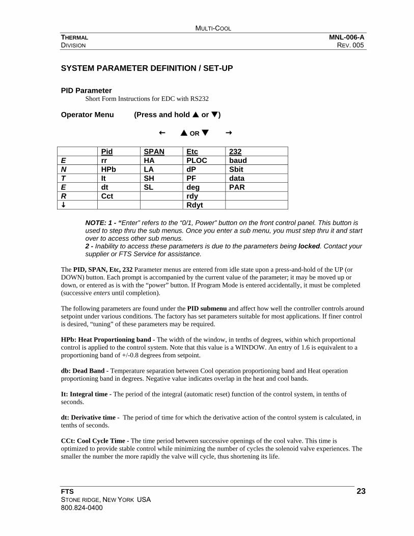
SYSTEM PARAMETER DEFINITION / SET-UP PID Parameter Short Form Instructions for EDC with RS232 Operator Menu (Press and hold or ) OR Pid SPAN Etc 232 E rr HA PLOC baud N HPb LA dP Sbit T It SH PF data E dt SL deg PAR R Cct rdy
Rdyt
NOTE: 1 - “Enter” refers to the “0/1, Power” button on the front control panel. This button is used to step thru the sub menus. Once you enter a sub menu, you must step thru it and start over to access other sub menus. 2 - Inability to access these parameters is due to the parameters being locked. Contact your supplier or FTS Service for assistance.
The PID, SPAN, Etc, 232 Parameter menus are entered from idle state upon a press-and-hold of the UP (or DOWN) button. Each prompt is accompanied by the current value of the parameter; it may be moved up or down, or entered as is with the “power” button. If Program Mode is entered accidentally, it must be completed (successive enters until completion). The following parameters are found under the PID submenu and affect how well the controller controls around setpoint under various conditions. The factory has set parameters suitable for most applications. If finer control is desired, “tuning” of these parameters may be required. HPb: Heat Proportioning band - The width of the window, in tenths of degrees, within which proportional control is applied to the control system. Note that this value is a WINDOW. An entry of 1.6 is equivalent to a proportioning band of +/-0.8 degrees from setpoint. db: Dead Band - Temperature separation between Cool operation proportioning band and Heat operation proportioning band in degrees. Negative value indicates overlap in the heat and cool bands. It: Integral time - The period of the integral (automatic reset) function of the control system, in tenths of seconds. dt: Derivative time - The period of time for which the derivative action of the control system is calculated, in tenths of seconds. CCt: Cool Cycle Time - The time period between successive openings of the cool valve. This time is optimized to provide stable control while minimizing the number of cycles the solenoid valve experiences. The smaller the number the more rapidly the valve will cycle, thus shortening its life.

MULTI-COOL THERMAL MNL-006-A DIVISION REV. 005
FTS STONE RIDGE, NEW YORK USA 800.824-0400
24
Controller Parameters – SPAN, Etc, 232 Each prompt is accompanied by the current value of the parameter; it may be moved up or down, or entered as is with the “power” button. If Program Mode is entered accidentally, it must be completed (successive enters until completion). dEG: Degrees - Centigrade or Fahrenheit. 0=Centigrade, 1=Fahrenheit. PF: Power Fail (Recovery) - If this parameter is set to 0, the power-recovery system is off. Application of mains power will result in an idle system. If this parameter has been set to 1, application of mains power will result in an idle condition had the system been idle when power was removed, or a run condition if the system had been running when power was removed. SH: Span High - It may be desired to limit accidental entry of setpoint(s) outside of a particular range. This value is the highest value for which the system will be permitted to control. SL: Span Low - The lowest temperature at which the system may control. For instance, if the heat-transfer medium is water, it is not desirable to control below 1 degree C. The user may thus prevent accidental entry of freezing temperatures. HA: High Alarm - The temperature which, if exceeded by the process temperature, causes application of the HA alarm message when the system is running. LA: Low Alarm - If the process temperature falls below this value, the LA alarm prompt is added to the process display. dP: Decimal Point - If set to 0 (no), process readout is displayed to the nearest integer value. If set to 1 (yes), process readout is rounded to tenths. PLOC: Parameter Lock - 0=off, 1=on. If PLOC is set to 0 the PID settings may be changed during idle or while the system is running, thus allowing dynamic adjustment. If PLOC is set to 1 then the PID can only be adjusted during the IDLE state and can not be set while the system is running. rdY: “Ready” Temperature Band - The temperature band about SP, in degrees, by which the system may be defined as “ready”. The “ready” value (0/1) is normally available via a query to the chiller via the RS-232. Note that this is a “band”. The default value of 5.0 thus equates to +/-2.5 degrees from the SP. The Ready Temperature operates in conjunction with the Ready Time described by the next parameter. rdYt: “Ready” Time Constant - A time constant, in seconds, which the software uses to determine the “ready” condition. A simple temperature band is useless for ready determination if the process has not yet stabilized at SP. The initial excursion into the Ready Band may be followed by overshoot beyond the band, yielding a false signal. The process temperature is therefore continuously integrated across a period of time defined by this constant to ensure that stability has indeed been achieved. Since the stability is determined by integration, slow processes will tend to yield a Ready in less time than the actual constant value. Fast processes which have slewed across a wide span will yield a Ready in a time longer than the constant due to early windup. This is, however, consistent with the probability that the process will overshoot the band.

MULTI-COOL THERMAL MNL-006-A DIVISION REV. 005
FTS STONE RIDGE, NEW YORK USA 800.824-0400
25
bAUd: Baud Rate for the RS232 control communications port may be set according to the following:
ID# Baud Rate 0 300 1 1200 2 2400 3 9600
Sbit: Stop Bits - The number of stop bits (1, 1.5, 2) may be selected. Par: Parity - Parity detection may be selected per the following:
ID# Parity 0 None 1 Odd 2 Even
DatA: Number of data bits. Choose 7 or 8 bits. The default is 7 bits.

MULTI-COOL THERMAL MNL-006-A DIVISION REV. 005
FTS STONE RIDGE, NEW YORK USA 800.824-0400
26
ERROR MESSAGES In addition to performing the “down” function, the DOWN button also functions as the “Message clear” button. If any of the systems errors, alarms, or the PF message is active, a single application of the DOWN button will clear the display and it will revert to its normal display. An attempt to clear a message display will succeed only if the condition (error or alarm) causing the message has been corrected. Otherwise, the message will continue to reappear until such time as the condition is corrected. Detectable errors in the chiller encompass three categories:
1. Mechanical/Electrical failure fatal to system operation (FSE) 2. Mechanical/Electrical failure, non-fatal (NFE) 3. Software (microprocessor) error (FSE)
In the first instance, an error has been detected which, if allowed to continue, can result in further damage to the system. In this instance the unit is automatically returned to idle (with the error message). In the second instance, the error is considered not fatal to system operation: either the system “doesn’t care”, or is able to proceed without correcting the problem. The 68000 family of microprocessors incorporates extensive error trapping (e.g., “illegal instruction” suggests that a programmer is trying to execute data rather than instructions). Since the chiller software is uniform and ROM-resident, the probability of encountering such an error is relatively small, but still exists. Should such an error occur, the software will restart from its “Power Recovery” routine (assuming it is enabled) and proceed as if power had been removed and reapplied. Should an error be suggested by the unit which cannot be traced to a fault by the user, FTS service personnel should be provided with both the error number and as complete a description as possible of what was happening when the error occurred, including:
Display mode Operation Mode (Run, Program, etc.) Process Temperature System Status (Cool on/off, PID values, etc.).

MULTI-COOL THERMAL MNL-006-A DIVISION REV. 005
FTS STONE RIDGE, NEW YORK USA 800.824-0400
27
Error Listing #0: NFE: Attempt to display a number larger than the display can handle. #1: NFE: “Minus” - No place to put the minus sign in the display. #2: FSE: Unknown task - Internal software error; system executive has been told to execute a task routine which doesn’t exist. #3: NFE: Analog-to-digital converter failed to provide a “conversion complete” signal. A software loop detects a timeout in the length of time the ADC is permitted to finish. If the ADC does not finish in the allotted time, the error results. NOTE: If this error is encountered, the unit should be shut down and the ADC replaced, or FTS Service should be consulted. #4: NFE: Overvoltage - A voltage too great for the ADC, and not otherwise defined as “overtemp”. #5: NFE: Overtemp - Usually an open RTD sensor, a reading outside the defined range of temperature resolution (-150C to +150C). #6: Low fluid ignored - This error will be generated if the user attempts to start the chiller while the “Low Fluid” LED is active. #20: through #30, inclusive: 68000 Microprocessor Errors. #20: System Error #21: Bus Error #22: Address Error #23: Instruction Error #24: Divide Error #25: Trap (Instruction) Error #26: Privilege Violation

MULTI-COOL THERMAL MNL-006-A DIVISION REV. 005
FTS STONE RIDGE, NEW YORK USA 800.824-0400
28
CALIBRATION Equipment required: -Calibrated temperature indicator
-Heater (optional) Set-Up 1. Fill reservoir with heat transfer fluid. CAUTION: The fluid being used must be stirrable at the maximum
low temperature. 2. Place calibrated temperature indicator into the fluid adjacent to 2” of the RTD sensor. 3. The cooling system may be difficult to stabilize without a heat load. To eliminate this problem, a heater
rated at 50% (the heat removal capacity of the system at 0°C) may be immersed in the reservoir and energized. This will provide a load to stabilize the temperature.
Calibration Procedure 1. Depress and hold the 0/I (off/on) button while plugging in the power to the unit. 2. The SP (setpoint) prompt and present SP will appear on the display. Use the Up > or Down ? buttons and
adjust the SP to 0.0, then press 0/I. The display will begin to alternate between “C oS” (cal offset) and the process temperature.
3. By setting 0.0 the Multi-Cool will attempt to cool to 0.0°C. Allow the system to stabilize at zero (wait at
least 15 minutes to allow electronics to stabilize). Using the Up > or Down ? buttons will adjust the measured process temperature up and down. Adjust the reading to match the temperature standard.
4. After the zero has been adjusted, press the 0/I button again and the SP prompt will return. The Span may be
adjusted either using a low temperature or using a high temperature. Calibrating at a Low Temperature If a heater was added for the zeroing procedure it must be removed. Wait for the temperature to stabilize at its maximum low temperature. 1. Adjust the setpoint to its minimum setting (-70°C) and then press 0/I again. The “C Gn” prompt will
appear. When the temperature stabilizes adjust the temperature to read the same as your temperature standard.
2. At -70°C, use Up > or Down ? buttons so the controller matches the temperature standard, approximately 0.1° per step.
3. Press 0/I. The display will flash “rFC?”. Using the Up > or Down ? buttons, set it to 0.
4. Press 0/I. The display will flash “Fin”. Using the Up > or Down ? buttons, set it to 0. Press 0/I again.
5. Repeat steps 1-4 of the calibration procedure, then steps 1 - 3 in this section to verify results.
6. When calibration is confirmed, using the Up > or Down ? buttons, set “Fin” to 369. Press 0/I.
7. To save the calibration, step through using the 0/I button until “SFC?” is displayed, and enter a 1.
8. Continue to step through until the process temperature reappears in display.

MULTI-COOL THERMAL MNL-006-A DIVISION REV. 005
FTS STONE RIDGE, NEW YORK USA 800.824-0400
29
RS232 PROGRAMMER INSTRUCTIONS
OVERVIEW The EDC controller is used in a variety of cooling products manufactured by FTS. The commands used by a specific system will vary per the descriptions at the end of this reference, but the operational aspects, hardware and software, of the interface are consistent across the product line. This document details the communications interface between the EDC microcontroller and the (independent) intelligent host processor. At the end of this section is a sample program which will execute on an IBM-compatible PC within either GWBASIC or QBASIC. It is suggested, should initial attempts to communicate be unsuccessful, that this program be tried. It is as unencumbered as a program may be and will aid in locating the source of difficulty. If this program runs successfully, then the difficulty must be due to one of the extras or features of the unsuccessful driver.
HARDWARE The hardware of the RS232 interface meets or exceeds the specifications of EIA standard RS-232-E-1991, with regard to electrical characteristics (impedance, open-circuit characteristics, voltages, etc.). The physical interface connector is a 9-position female D-subminiature connector, with pin-out as specified by the IBM Corporation for the "PC-AT" [COM1] communication port. The connections used within the interface will be limited to: GND Signal Ground TXD Transmit Data RXD Receive Data RTS Request to Send CTS Clear to Send DTR Data Terminal Ready DSR Data Set Ready The pinout for a fully wired null modem cable is: 2-3, 3-2, 4-4, 5-5, 6-7, 7-6, 8-8 All other signals of the RS232 standard are immaterial to this application, or terminated, as appropriate.
COMMUNICATIONS Communication operates at a user-definable BAUD rate selectable from 300, 1200, 2400, 9600. Parity may be odd, even, or none. The interface uses one Start bit and either one, one-and-a-half, or two Stop bits (user-selectable). Data word length is selectable at 7-bit data with designated parity, or 8-bit data without parity. All data in both directions is transmitted in ASCII.

MULTI-COOL THERMAL MNL-006-A DIVISION REV. 005
FTS STONE RIDGE, NEW YORK USA 800.824-0400
30
Selections of BAUD rate, parity, and stop bits are made to the EDC microcontroller via the control panel of the target (application) system. Communication Data All programmable, selectable, or switchable functions of the target system are accessible via the RS232, with the exception of the RS232 configuration itself, which may not be programmed from the host. All data, programmed values, status, and system errors are accessible by the host, i.e., an appropriate query by the host will result in a data stream returned from the EDC as defined below. Data Format All data is transmitted in ASCII. All data values are transmitted via decimal character strings. Upper and lower case alphabetic characters will be accepted interchangeably. Data descriptions are identified by direction from the perspective of the system controller: Received (from the host system to the EDC) and Transmitted (from the EDC to the host) data. Received Format Data may be transmitted at any time by the host to the EDC. Status queries will be answered whether or not the unit is in local or remote. Any change in system status (except "Goto Remote") requested via the RS232, however, will require that the unit be in the "remote" state; otherwise an error will be reported to the host. Data uses a "line" format, consisting of the following:
CMD <opt CMD> <opt CMD> <...> CR <opt LF> Where:
CMD is any valid transmitted data string CR is an ASCII "Carriage Return" LF is an ASCII "Line Feed"
Data commands may be grouped within a line command, or transmitted singly. A data string must be terminated by a "Carriage Return" (ASCII 013 decimal / 0D hex). "Line Feed" (ASCII 010 decimal / 0A hex) may be optionally inserted by the host, but will be ignored by the EDC. A line may not exceed 128 characters. A listing and description of the available CMD statements appears in a later section. Data commands which are grouped on a line must be separated by a single "Space" (ASCII 032 decimal / 20 hex). The Delete/Rubout character (ASCII 127 decimal / 7F hex) will NOT be recognized. Unrecognized characters will result in an error acknowledge. ANY error in transmission / reception of a line will assume corruption of the ENTIRE line, and ALL commands in that line will be ignored. This includes not only transmission (e.g., parity) errors, but values out-of-bounds, undefined commands, etc. This ensures that state changes are not presented to the system (e.g., new Setpoint SP) without all corresponding desired changes (such as corresponding PID values).

MULTI-COOL THERMAL MNL-006-A DIVISION REV. 005
FTS STONE RIDGE, NEW YORK USA 800.824-0400
31
All data received by the target system will be presented by the host system as a character string of one of the following formats: Absolute Command Basic system functions/commands will consist of a fixed character string. Examples:
"START" -- Wake up system "STOP" -- Shut down system "POLL" -- Force a response from the system
Parametric Command A parametric command describes a function/command for which a value must be specified. The command characters must be followed by an equals sign (=) (ASCII 061 decimal / 3D hex), and a data string of decimal value. The value may optionally contain a decimal point (except where required to define decimal fractions). Negative values require a minus sign (-), (ASCII 045 decimal / 2D hex) between the equals sign and the value. A plus sign (+) may be used, but is not required. Each programmable value within the system is assigned a set of limits by the system. Certain of these limits may be further modified by other program commands. Values which exceed the boundaries of either of these limits will result in an error. The number of characters attached to the "value" field may not exceed eight; an error will result accordingly. Leading zeroes, or trailing zeroes behind a decimal point, may be added without effect, up to the character limit. Examples:
SP=20 ;Adjust Setpoint to 20 degrees SP=+20. ;Adjust Setpoint to 20 degrees SP=020.00 ;Adjust Setpoint to 20 degrees SP=-60.3 ;Adjust Setpoint to -60.3 degrees CPB=3.6 ;Adjust Cooling Proportioning Band to 3.6 degrees
Controllable features which are not system "program parameters", such as switches, use the values "0" to represent "off" and "-1" to represent "on" (byte false = $00 = 0, byte true = $FF = -1). Examples:
PUMPSW=-1 ;Turn pump switch on PUMPSW=0 ;Turn pump switch off
Query Command (request for information) A request for information from the EDC to the host is an absolute command. However, all commands which expect data in reply to the command end with a question mark (?). The format of the reply is defined below (see Transmitted Data). With few exceptions, the query command replicates the mnemonic for the corresponding parametric command, merely substituting the (?) for the (=) in the string.

MULTI-COOL THERMAL MNL-006-A DIVISION REV. 005
FTS STONE RIDGE, NEW YORK USA 800.824-0400
32
Transmitted Data It is anticipated that in a remote-controlled operation of the target system, the actual controlling device may be either a computer with a software program, or a human being working interactively. The format of returned data has been optimized for evaluation by a computer program, although it can be intelligently read by a human working in an interactive mode. The content of transmitted data to the host is dependent upon the type of received data to which the EDC is answering. The returned message consists of one or more segments: Acknowledge: receipt and acceptance of a message which is syntactically correct, meets all constraints or limits imposed by the system, and which has been subsequently processed, is acknowledged by the character string "OK". Exception: certain absolute commands may result in a “runtime” error (in other words, will result in an error when the software attempts to actually execute the statement). These will result in both “OK” and the error message described below. Error Message: receipt of a message which is syntactically incorrect, exceeds system limits, or is otherwise faulty (such as Parity Error), will result alternately in an error message. Parameter Message: in response to a query, the parameter and its value will be returned to the host. If multiple value/status queries are transmitted in a single statement, the multiple replies will be transmitted on multiple lines (i.e., separated by carriage returns). Terminator Character: All messages will be terminated by an exclamation point “!” (ASCII 033 decimal / 21 hex). This character is appended to a single-line message, including "OK", or to the end of the last line of a multiline message if the host has transmitted queries. The EDC is capable of full-duplex operation; i.e., it is capable of receiving data while transmitting data. However, it is strongly suggested that the host wait for the message:
“OK” and the exclamation point ("!") before proceeding to its next transmission to the EDC, to ensure correlation between information sent and the replies. The Command POLL has been provided as a non-operative command (similar to an assembly-language NOP or BASIC-language REM) to verify establishment of communications between the host and the EDC. The POLL command will have no effect on the state of the EDC or the target system, and can result in an error only if the RS232 connection itself is not correct (e.g., wrong BAUD rate, parity error, etc.). Once the POLL command has been issued, and the string "OK!" has been received by the host, the software may be assumed to be synchronized. User software should be configured to transmit a message (received data), receive the reply (transmitted data), and verify the integrity of the exchange before proceeding to the next transmission.

MULTI-COOL THERMAL MNL-006-A DIVISION REV. 005
FTS STONE RIDGE, NEW YORK USA 800.824-0400
33
Transmitted Data Format Acknowledge The explicit characters "OK" acknowledge receipt of a valid message, followed by 11 spaces (not counting the space for line continuation, described below). Error The line begins with the character "E", followed by a 3-digit decimal value defining the error number. It is up to the user to provide necessary messages defining the error, if desired. A full listing and description of error numbers is provided in a later section of this document. An equals sign (=) follows, and is then followed by a plus (+) and 7-digit explanation code. For character-traceable errors, the number indicates the column position of the character which resulted in the error. Positions are numbered 0-127, 0 representing the first character and 127 the last permissible character. If the error is due to a general error (e.g., "LINE TOO LONG"), the character-trace code is 128. Example A:
Received string: START Transmitted string: E030=+0000128!<CR> (Error 30 = "Unit Not in Remote")
Example B:
Received string: SP=25 CPB=2.5 IT=35,0 DT=6 Transmitted message: E021=+0000019!<CR> (Error 21, Illegal character, in position 19)
Value The line begins with the character "F" (Function), followed by a 3-digit decimal code defining the opcode number assigned to the parameter. Following the function code is an equals sign (=) and an 8-character value. This value will ALWAYS begin with a polarity sign (+ or -), followed by either 7 digits; or 6 digits with an embedded decimal point. The value 0 will always be positive. All temperatures in the EDC are internally resolved to 0.01°F. Temperature values will always be returned with full resolution on the RS-232 regardless of the resolution of the control panel display or the user display options. Temperature values will be transmitted to the host in the units (C, F, K scale) selected by the DEGREES= command (or via the dEG setting in the control panel “Etc” menu).

MULTI-COOL THERMAL MNL-006-A DIVISION REV. 005
FTS STONE RIDGE, NEW YORK USA 800.824-0400
34
Values for system characteristics which are not programmable parameters (e.g.: switches, on/off status, etc.,) will be returned as byte status. In other words, if the state is true, the returned value will be -0000001 (byte true hex FF); if the queried status is false, or off, the returned value will be +0000000 (byte false hex 00). Example:
Received string: SP? Transmitted message: OK <CR> F057=-0030.00!<CR> (Function #57, Setpoint, is currently -30 degrees)
Terminator The exclamation point ("!") is issued prior to the last <CR> to indicate "end of message", so that multiline messages may be accommodated. To facilitate message parsing by column position, this position is left with a "space" if the line is not the last of the message. Command Set The following commands are defined to the interface. Certain commands, while syntactically acceptable to the parser, will result in the error code "Not Yet Implemented" (nyi); these have been defined for future expansion or options. The command opcode (function "F" number) which will be returned by a query appears in curly-brackets following each query command. Upper case is used to note other (referenced) commands. ALARMH= / ALARMH? {F001} Set or query the user setting of the overtemperature (high) alarm condition, in degrees. Limits are imposed by FLUID= and the factory-set system span (SSPANH). ALARML= / ALARML? {F002} Set or query the user setting of the undertemperature (low) alarm condition, in degrees. Limits are imposed by FLUID= and the factory-set system span (SSPANL). ALMCODE? {F076} Query the status of the system alarm table. A reply of 0 indicates a no-alarm condition. Other codes are documented in a separate section, below. BAUD? {F003} Report the present BAUD rate in use in the communication link. Values returned will be the same as those programmed via the system control panel: 0=300, 1=1200, 2=2400, 3=9600. CASC? (Service Use) {F004} Report the existence of a two-stage refrigeration system (0=single compressor, 1=cascade). CBLI? (Service Use) {F005} Report the configuration of cool/bypass/liquid injection valves in a given system configuration.

MULTI-COOL THERMAL MNL-006-A DIVISION REV. 005
FTS STONE RIDGE, NEW YORK USA 800.824-0400
35
CCT= / CCT? {F006} Set or query the Cool Cycle Time: the on/off period assigned to the proportioning cooling valves, in seconds. CH= / CH? (Not Yet Implemented) {F007} Define steering of loop-dependent commands to ch.1 or ch.2 in a dual-loop system. CLOCK= / CLOCK? (Not Yet Implemented) {F008} Define or query the existence of Real Time Clock hardware. CLRALARM Clear alarm conditions from the system, if any exist. Restore ALMCODE? to 0. If the condition creating the alarm state persists, however, the system will restore the alarm until that condition is corrected. CPB= / CPB? {F010} Set or query the width, in degrees, of the band about setpoint (SP) over which the control system will proportion the cooling valves (Cool Proportioning Band). CTLREM= / CTLREM? {F011} Set or query the use of the remote sensor for temperature control of the system. Value 0 (off) means "control from the internal sensor"; 1 (on) means "control from the remote sensor". If the remote sensor is not connected (open circuit), the system will automatically revert to internal-sensor control and an alarm will result. CURRSNS? (Service Use) {F012} Query the existence of pump/compressor current sensors as defined by the system hardware complement (factory set). 0 = off/don't exist; 1 = on. DATE= / DATE? (Not Yet Implemented) {F013} Set or query date in Real Time Clock option. DB= / DB? {F014} Set or query the deadband, in degrees, between the heat and cool proportioning bands (HPB/CPB). This value is usually negative, implying overlap. DEFAULT (Not Yet Implemented) Restore factory default values to the programmable parameter table. DEGREES= / DEGREES? {F016} Set or query the temperature scale used on the display and in further RS-232 communications. 0 = Celsius, 1 = Fahrenheit, 2 = Kelvin. DP= / DP? {F017} Set or query the use of integer/decimal format on the control panel display. 0 (decimal point off) displays temperature rounded to the nearest integer; 1 (decimal point on) displays temperature with 0.1 resolution. DT= / DT? {F018} Set or query, in seconds, the [derivative] time constant applied to the proportioning band adjustment, as a function of rate of change in the process temperature.

MULTI-COOL THERMAL MNL-006-A DIVISION REV. 005
FTS STONE RIDGE, NEW YORK USA 800.824-0400
36
FLUID= / FLUID? {F019} Set or query the number defining the fluid type in use in the system (see system programming documentation for a listing). Fluid definition automatically sets FSPANH and FSPANL, subject to SSPANH and SSPANL, to limit the permissible bounds of the setpoint SP and the alarm temperatures ALARMH and ALARML. FORMAT= / FORMAT? (Not implemented / obsolete) {F020} Describes the format of transmitted data. Task offloaded to the host processor. FSPANH? {F021} Query the high temperature limit (degrees) established by the FLUID definition. FSPANL? {F022} Query the low temperature limit (degrees) established by the FLUID definition. GNREM= / GNREM? {F023} Adjust or query the calibration gain factor applied to the remote (external) temperature sensor. GNRTD= / GNRTD? {F024} Adjust or query the calibration gain factor applied to the system (internal) temperature sensor. HEATER? (Service Use) {F025} Query the system heater configuration and phase connection definition. HLPC? (Service Use) {F026} Query the existence of high-low-pressure cutout on the system compressor(s). Used in water-cooled units. 0 = not used, 1 = exists. HPB= / HPB? {F027} Set or query the width, in degrees, of the band about setpoint (SP) over which the system will proportion the power applied to the heater (Heat Proportioning Band). HYSTLI? (Service Use) {F028} Query the hysteresis, in degrees, applied to activation of the liquid injection valve. HYSTST2? (Service Use) {F029} Query the hysteresis, in degrees, applied to measurement of the cascade condenser (first refrigeration stage output), for operation of the second-stage refrigeration. IT= / IT? {F030} Set or query the [integral] time constant, in seconds, applied to the adjustment of the proportioning band, governing the automatic reset ("droop" correction) of the process temperature to setpoint. NOTE: the IT value is applied only to the internal temperature-control sensor. If the remote sensor is in use (CTLREM=1), the command ITREM should be used. The proper selection of IT or ITREM is automatically performed by the system software per the CTLREM command. ITREM= / ITREM? {F031} Set or query the (integral) time constant, in seconds, applied to the adjustment of the proportioning band, governing the automatic reset ("droop" correction) of the process temperature to setpoint, when the remote sensor is in use (Cf. IT=). LOCK= / LOCK? {F032} Set or query the state of the Local / Remote lockout. If set to 0, the LOCREM= command may be asserted. If set to 1, the LOCREM= command will result in an error message.

MULTI-COOL THERMAL MNL-006-A DIVISION REV. 005
FTS STONE RIDGE, NEW YORK USA 800.824-0400
37
LOCREM= / LOCREM? {F033} Set or query the local / remote control status of the system. If set to 0, the system may only be programmed from the (local) control panel. If set to -1, the system may only be programmed from the remote communication link. If the system is in local control (LOCREM=0), all commands AAAAAAAA=, except the LOCREM= command, will result in the error message "unit is in local". Queries will perform normally. If LOCK=1 the LOCREM= message will return the error message "unit is locked in local/remote". LOOP2? (Service Use) (Not Yet Implemented) {F034} Query existence of a second control loop, in dual-loop systems. MODE? {F035} Query the control configuration of the system (factory-set per configuration). 0 = heat and cool, 1 = cool only, 2 = heat only. NOISE= / NOISE? {F036} Set or query the action of the audible alarm (activated under fault conditions in conjunction with the red alarm lamp on the control panel). 0 = "off", 1 = intermittent "chirp", 2 = continuous "on". OSREM= / OSREM? {F037} Set or query the calibration offset factor applied to the remote (external) temperature sensor. OSRTD= / OSRTD? {F038} Set or query the calibration offset factor applied to the system (internal) temperature sensor. PARITY? {F039} Query the parity setting of the communication link. 0 = no parity, 1 = odd, 2 = even. PF= / PF? {F040} Set or query the selection of the automatic power recovery algorithm. 0 = disabled, 1 = enabled. PLOCK= / PLOCK? {F041} Set or query the status of the parameter lockout feature of the control panel. If set to 1, menu values may not be changed from the control panel while the system is running, even if the unit is in "local" operation. If set to 0, the system may be fully programmed from the control panel at any time if the unit is in "local". If PLOCK has been set to 1, system operating parameters may only be changed from the control panel if the unit is first turned off (STOP). POLL A non-operative command which may be used to test or synchronize the communications interface. PT? {F043} Query the current process temperature (as defined by the control point CTLREM). PTLOC? {F044} Query the current local process temperature (per the internal sensor). PTREM? {F045} Query the current remote process temperature (per the remote sensor). PUMP? {F046} Query the status of the circulating pump. 0 = off, -1 = on. PUMPSW= / PUMPSW? {F047} Set or query the state of the pump switch. 0 = (turn) off, -1 = (turn) on.

MULTI-COOL THERMAL MNL-006-A DIVISION REV. 005
FTS STONE RIDGE, NEW YORK USA 800.824-0400
38
RAMZERO (Not Yet Implemented) Command to zero out the microprocessor memory for restart of a "dead" unit. READY? {F077} Query state of process ready-determination stability algorithm (0 = not ready/stable, 1= ready/stable) per program values SP, WINDOW, and WINTIME. REFR? {F050} Query state of refrigeration. Returned 0 = off, 1 = 1st stage on, 2 = 2nd stage on (if cascade system). REFRHRS? {F078} Query running hours of system refrigeration. REFRSW= / REFRSW? {F051} Set or query state of refrigeration switch. 0 = off, -1 = on. REV? {F052} Query (embedded) software revision level in system program ROM. RFC Command to restore factory-determined calibration constants. RR= / RR? {F054} Set or query setpoint transition rate (Ramp Rate), in degrees per second. STOPBITS? {F055} Query the programmed number of Stop bits in the RS232 communication definition. Values may be 1, 1.5, or 2. SP= / SP? {F057} Query or set the system temperature setpoint, in degrees. SSPANH? {F058} Query the factory-set maximum allowable setpoint, in degrees (determined by system hardware complement). SSPANL? {F059} Query the factory-set minimum allowable setpoint, in degrees (determined by system hardware complement). START / START? {F060} Command to turn the system on (subject to positions of PUMPSW and REFRSW) and to initiate the system temperature control software. Query to determine whether the system is running ( 0 = off, -1 = on). STATUS? (Not implemented, obsolete). STOP Command to turn the system off, restore displays and controls to idle. SYSHOURS? {F063} Query number of running hours accumulated on the system, as determined by the number of running hours on the pump. TEMPLI? (Service use) {F064} Query temperature, in degrees, of suction line, for control of liquid-injection valve in refrigeration hardware.

MULTI-COOL THERMAL MNL-006-A DIVISION REV. 005
FTS STONE RIDGE, NEW YORK USA 800.824-0400
39
TEMPST1? (Service use) {F065} Query temperature, in degrees, of the cascade condenser (heat-exchanger output of the first refrigeration stage in a two-stage system). TIME= / TIME? (Not yet implemented) {F066} Set or query time of day in Real-Time Clock option. TRIPLI? (Service use) {F067} Query factory-programmed trip temperature of suction line, to determine operation of the liquid injection valve. TRIPST2? (Service use) {F068} Query trip temperature, in degrees, of cascade condenser, for turn-on of the second stage refrigeration. UPHOURS? {F069} Query total hours of system operation (including off), from engagement of Emergency Off switch. USPANH= / USPANH? {F079} Set or query SP upper operating limit, in degrees, as determined by the user's requirement. This limit may not exceed the value FSPANH? or SSPANH? USPANL= / USPANL? {F080} Set or query SP lower operating limit, in degrees, as determined by the user's requirement. This limit may not be more negative than the value FSPANL? or SSPANL? WAKE= / WAKE? (Not Yet Implemented) {F070} Set or query the status of the automatic-wakeup function. WAKEMINS= / WAKEMINS? (Not Yet Implemented) {F071} Set or query the elapsed time to automatic wakeup. WAKETIME= / WAKETIME? (Not Yet Implemented) {F072} Set or query the automatic-wakeup time set via Real-Time Clock option. WINDOW= / WINDOW? {F073} Set or query the window, in degrees, used to determine process stability (conformance to setpoint), as reported by the system "Alarm/Ready" contacts. WINTIME= / WINTIME? {F074} Set or query the time constant, in seconds, used to determine process stability (conformance to setpoint), as reported by the system "Alarm/Ready" contacts. This time is a time constant used in the stability integration and determination algorithm, not an absolute time value. Small movements in process temperature will be determined to be stable more rapidly than large swings. This value is used to prevent over/undershoot of the setpoint temperature from yielding a premature "ready" result. ZEROCAL (Not Yet Implemented) Command to restore all calibration constants to the unbiased state (zero offset, unity gain).

MULTI-COOL THERMAL MNL-006-A DIVISION REV. 005
FTS STONE RIDGE, NEW YORK USA 800.824-0400
40
ALARM CODES Numeric codes are returned to the query ALMCODE? per the following alarm conditions. Alarms, once set, are maintained until explicitly cleared, even if the alarm condition has been corrected. Code 0: No outstanding alarm condition. Code 1: Low fluid level in system. Code 2: Low fluid flow in system (inadequate pressure in return line). Code 3: Insufficient cooling water in water-cooled system. Code 4: Stage 1 Refrigeration is not powered, as determined by current sensors. This failure can be due to (internal) overtemp cutouts, trip of a circuit breaker, etc. Code 5: Stage 2 Refrigeration is not powered. See Code 4. Code 6: Pump is not powered. May be not powered, fuse may be blown, etc. Code 7: System has been programmed for control from Remote sensor. Remote sensor is open-circuit. Code 8: High temperature alarm. Process temperature exceeds ALARMH? Code 9: Low temperature alarm. Process temperature has fallen below ALARML? Code 10: Same as Code 4, for a single-stage (only one compressor) system. Code 11: Overtemp. Indicates activation of fail-safe (control-independent) overtemperature safety device. Code 12: 4-20mA Alarm. Indicates disconnect of 4-20mA current source to remote analog programming input, if such interface is specified.

MULTI-COOL THERMAL MNL-006-A DIVISION REV. 005
FTS STONE RIDGE, NEW YORK USA 800.824-0400
41
RS232 ERROR CODES The following error codes are returned Ennn if the parser/syntaxer/limits-checking software finds fault with the received string. Group 0: UART Transmit/Receive and General Receive errors. E001 UART Overrun Character received by UART before previous character has been retrieved from the character input buffer. Microprocessor hardware failure. E002 Parity Error Character detected has incorrect parity as defined by control-panel programming. See PARITY? E003 Frame Error Incorrect number of Stop Bits detected on received character. See STOPBITS? E004 Break Error UART detects loss of RS-232 line with host. This error is only reported if such a break occurs after the receipt of valid data, and before receipt of a <CR> (carriage return). Line break is otherwise ignored. E005 Line Too Long Received "line" (character string) exceeds 128 characters without receipt of <CR> (carriage return). E006 Receive Buffer Overrun 1KB character input buffer is full. Commands are being received faster than they can be processed. E007 Line Buffer Overrun Lines are being received faster than they can be processed. E008 Break Error See E004. Group 1 Errors: General Parsing and Transmission Errors E010 Transmit Buffer Overflow Requests for information (queries) result in information being buffered faster than it can be transmitted to the host (Baud-Rate dependent). 1KB buffer exceeded. E011 Parse Buffer Overflow Too many commands (>32) on a single line. Group 2 Errors: Command Parsing Errors E020 Undefined String Character string not identified as valid command, in position indicated by trailing argument. E021 Illegal Character Character in string not a recognized character (A-Z, a-z, 0-9, =, ?, ., +, -, <SP> (space), <LF> (line feed), or <CR> (carriage return). E022 Illegal Operand Keyword string followed by illegal operation (command, program, query). E.g., TEMPST1 may only be queried; is a temperature which exists in the system and is measured. Attempt to program via TEMPST1= will yield E022. E023 Question Mark (?) Followed by Argument Query will not accept an argument. E024 Value Too Long Programmed value may not exceed 8 characters.

MULTI-COOL THERMAL MNL-006-A DIVISION REV. 005
FTS STONE RIDGE, NEW YORK USA 800.824-0400
42
E025 Illegal Sign Placement or Excess Decimal Points Polarity indication (+,-) must be first character. Only one decimal point permitted per number. E026 Too Many Decimal Places Too many digits supplied after decimal point. E027 Value Out of Bounds Programmed number exceeds limits fixed internally or by superseding limits (e.g., FSPANH will limit USPANH). E028 Excessive number The previous filters will allow certain (illegal) ranges of numeric possibility to get through. This error traps these ranges before they cause software mathematics errors (due to register overflow, etc.). Group 3: Security Errors E030 Unit Not in Remote Attempt has been made to program a value which may not be altered if system is presently switched to local operation. E031 Not a User Function Certain program statements are reserved for factory access. Error 31 reports an attempt to program values requiring (factory) security-code access. Group 4: Operational and Miscellaneous Errors E040 Not Yet Implemented Use of a command which is defined to the parser but not presently implemented by FTS. E041 Stop Error System already stopped has received a "STOP" command. E042 Start Error System already started has received a "START" command. E043 Not a User Function Certain operational commands are defined to the system and reserved for factory use. Error 43 reports use of such a command without proper security access. E044 Local Lockout Unit is locked in local. Removal of this lock may only be accomplished from the system control panel before changes to system state may be made from the RS232.

MULTI-COOL THERMAL MNL-006-A DIVISION REV. 005
FTS STONE RIDGE, NEW YORK USA 800.824-0400
43
SAMPLE PROGRAM The following program is supplied to assist in troubleshooting should the user’s attempts to communicate via the RS232 be unsuccessful. It will execute properly from either GWBASIC or QBASIC on an IBM-compatible PC. If this program runs, the alternate driver has a software or configuration problem. If this program does not run properly, a hardware problem (usually a mis-wire) is indicated. This program was designed to be as simple as possible. It therefore performs no syntax checking or error detection. It will prompt “COMMAND?”, to which the user should type the string desired to send (e.g., “SP?<CR>”). The character string returned by the EDC will be displayed on the user’s terminal. Users will note that the transmit/receive strings appear to be out of synch on the terminal display; this is also to keep the program as short and unencumbered as possible. The Rubout, Backspace, and Delete keys will NOT work. They will be transmitted like any other character (and will result in an error message “Illegal Character”). Once the program has been typed into BASIC (or loaded from disk), it may be run from GWBASIC by typing “RUN”, or from QBASIC from ALT-R-S or Shift-F5. To stop the program, use CTL-BREAK. 5 OLINE$="" 10 OPEN "COM1:9600,N,7,1,RS" AS #1 20 PRINT "COMMAND: "; 30 A$=INKEY$ 40 IF A$="" THEN GOTO 110 50 PRINT A$; 60 OLINE$=OLINE$+A$ 70 IF A$ <> CHR$(13) THEN GOTO 30 80 PRINT #1,OLINE$; 90 OLINE$="" 100 GOTO 20 110 WHILE NOT EOF(1) 120 B$=INPUT$(LOC(1),#1) 130 PRINT B$; 140 WEND 150 GOTO 30

MULTI-COOL THERMAL MNL-006-A DIVISION REV. 005
FTS STONE RIDGE, NEW YORK USA 800.824-0400
44
FTS SERVICE AND WARRANTIES
SERVICE CONTACT If you require service on your unit, please contact: FTS Service Department 3538 Main Street, PO Box 158 Stone Ridge, N.Y. 12484 Telephone: (845) 687-0063 or (877) 548-4666 FAX: (845) 687-0024 [email protected]
SERVICE AGREEMENT The FTS Service Division was founded in January of 1971. Our technicians are fully trained to service all electrical, refrigeration, liquid, vacuum, air, and vapor control systems manufactured and sold by FTS. We service all FTS products throughout the world from our home office located at the FTS manufacturing facility in Stone ridge, NY. In addition to factory support personnel, we have a worldwide network of qualified service organizations ready to accommodate you and your service needs. Customer satisfaction is our number one priority. Our goal is to provide the finest quality service promptly, at the best price possible. We recognize that a satisfied customer is our most valuable asset! A timely solution to a service problem is best achieved by establishing good communication with the FTS Service Division. We will furnish the appropriate qualified service support group for your area. Should you require repair services or parts for your FTS equipment, please contact us at your convenience. We will discuss your requirements and suggest the best means to get you back on line as fast as possible.

MULTI-COOL THERMAL MNL-006-A DIVISION REV. 005
FTS STONE RIDGE, NEW YORK USA 800.824-0400
45
STANDARD WARRANTY The FTS standard domestic warranty follows. This warranty covers parts and labor for a period of one year, commencing the date of invoice, for any repairs deemed resultant of a defect in materials and/or workmanship by FTS, F.O.B. Stone Ridge. Any factory approved changes or extensions to this warranty should be received in writing from FTS and filed with this warranty. If your system is eligible for coverage, please review this warranty thoroughly and contact the FTS Service Division with any questions you may have. If your system is not covered by our standard warranty, or you are seeking optional or additional coverage, see sections below for service plans offered. Covered:
• Parts and labor for a period of one (1) year from date of delivery. Any part found defective will be either repaired or replaced at FTS discretion, free of charges by FTS, at Stone Ridge, N.Y.
• On site labor if repairs require that FTS personnel travel to the equipment.
• Necessary parts and reasonable labor charges, if FTS agrees that local service is preferable. These parts and labor charges are subject to written approval prior to initiating the repair.
• Travel time, mileage, travel and transportation expenses expended by FTS personnel if repairs require on-site labor.
• Transportation of the equipment for repair.
Not Covered:
• FTS is not responsible for incidental or consequential damages, or damage resulting from negligence.
This writing is a final and complete integration of the agreement between the customer and FTS. FTS makes no other warranties express or implied, of merchantability, fitness or otherwise, with respect to the goods sold under this agreement, which extend beyond the description of this limited warranty. FTS will have the right to inspect the equipment and determine the repairs or replacements necessary. The customer will be notified within a reasonable time of any damages incurred that are not covered by this warranty prior to initiation of any such repairs. Any customer modification of this equipment, or any repairs undertaken without the prior written consent of FTS will render this limited warranty void.

MULTI-COOL THERMAL MNL-006-A DIVISION REV. 005
FTS STONE RIDGE, NEW YORK USA 800.824-0400
46
SERVICE OPTIONS Extended Warranty: This plan is an extension to the original new purchase warranty. You may extend the original warranty for six or twelve months up to a maximum of two years total coverage. This plan does not provide Preventative Maintenance, nor does it cover travel or any freight expenses incurred. Preventative Maintenance: This plan provides our customers with two onsite visits per year. We would perform a thorough preventative maintenance on your FTS equipment. You will be provided with a PM checklist and a certificate of calibration, which is traceable to N.I.S.T. The purchase of this plan also provides discounted parts and labor rate for additional service if required. Full Service Agreement: This plan covers 100% of expenses for travel, lodging, parts and labor. The FULL SERVICE AGREEMENT is your total protection plan. This plan enables the end user to contact FTS Service without going through the purchasing department. (Because the plan is pre paid.) A thorough Preventative Maintenance visit is included with the full service agreement. The PM visit includes calibration of your equipment and a certificate of calibration that is traceable to N.I.S.T. The purchase of the Full Service Agreement ensures premium service for any repair performed on site or at FTS. Contact FTS Service at (845) 687-0063 or (877) 548-4666for details.

MULTI-COOL THERMAL MNL-006-A DIVISION REV. 005
FTS STONE RIDGE, NEW YORK USA 800.824-0400
47
RETURN OF FTS EQUIPMENT If it is necessary to return the equipment to our factory, please contact the FTS Service Division at (800) 722-7721 for a Return Authorization (RA) number, and instructions on returning the unit. Please provide the model number, serial number, and order number. After receiving an RA number, return the unit, freight prepaid, to the following address:
FTS PO Box 158 3538 Main Street Stone Ridge, N.Y. 12484 U.S.A. Attn: Service Division RA# _________
Make sure the RA number and the declared value of the unit is plainly marked on your shipping label. FTS will refuse any equipment returned without a RA number, without freight prepaid, or with an expired RA number. This number is valid for 30 days, if your RA number expires you must request a new number. Before working on systems that are not under warranty, the Service Division will provide you with an estimate of the time and cost for the repair of your unit. No work will be started until FTS receives a hardcopy of your purchase order for the repair work. This also applies to warranty work when the customer is responsible for the shipping costs. Normally, we will repair your unit and return it within 10 working days of receipt. If your repair is urgent, you may authorize an emergency repair fee, which guarantees repair and return of your unit within 4 working days of receipt. Unless you specify otherwise, we will return the repaired unit F.O.B. from our Stone Ridge, New York factory, via ground transportation.

MULTI-COOL THERMAL MNL-006-A DIVISION REV. 005
FTS STONE RIDGE, NEW YORK USA 800.824-0400
48
ACCESSORIES
OVERVIEW This document describes the Charpy Rack accessories CRA-4 and CRA-8 for the FTS Multi-Cool system. CRA-4 The CRA-4 is designed for use with the 4-liter version of bath.
• It holds up to 65 specimens. • The system is supplied with 5 charpy racks. • Each rack is capable of holding 13 samples.
CRA-8 The CRA-8 is designed for use with the 8-liter version of bath.
• It holds up to 91 specimens. • The system is supplied with 7 charpy racks • Each rack is capable of holding 13 samples.
These racks slide onto rods mounted on the stirring assembly. Each system is also supplied with a lifting handle (RLH-1) for removing the racks from the bath. For set up and operation, follow the Stirrer instructions in the Multi- Cool manual.
C R A - 4 / 8 CHARPY RACK ACCESSORIES
CHARPY RACK