Embed Size (px)
Citation preview
Rotary Evaporator Bath
Instruction ManualSTU0001 / Version 1.0

2
IntroductionThank you for purchasing this Stuart product. To get the best performance from the equipment, and for
your own safety, please read these instructions carefully before use.
Before discarding the packaging check that all parts are present and correct.
1 RE400DB or RE400DB
(RE400DB shown)
2 UK power lead
3 Euro power lead
4 Warranty card
5 Instruction manual
6 Spare fuses x2
(RE400DB only)
Note: Additional packing material may be present.
This equipment is designed to operate under the following conditions:
v For indoor use only
v Use in a well ventilated area
v Ambient temperature range 5°C to 35°C (41°F to 95°F)
v Altitude to 2000 m (6500 ft)
v Relative humidity not exceeding 60% and free from condensation.
v Mains supply fluctuations not exceeding 10% of nominal
v Overvoltage category II IEC60364-4-443
v Pollution degree 2 IEC664
v Use with a minimum distance all round of 200 mm (8 in.) from walls or other items
If the equipment is not used in the manner described in this manual and with accessories other than those
recommended by the manufacturer, the protection provided may be impaired.
1 2
3
4 5
6

3
General Description
Your Rotary Evaporator Bath has been designed to be used with the Stuart range of Rotary Evaporators. They
are designed for general purpose laboratory use in which samples are gently heated in a Florentine flask to cause
evaporation during rotation.
Important Safety Advice
This equipment is classified as Class 1 (IEC519:part 2) with regard to over temperature protection and should be
used accordingly. Users should be aware of the following safety advice:
v SHOCK HAZARDS OR UNSAFE PRACTICES ARE DANGEROUS as they can cause severe personal injury, fire
or death.
v DO NOT use combustible substances near hot objects.
v DO NOT use the equipment in hazardous atmospheres.
v DO NOT operate or handle any part of the product with wet hands or use on surfaces that may become flooded.
v NEVER move the product while still connected to the power supply.
v HIGH TEMPERATURES ARE DANGEROUS as they can cause serious burns to operators and ignite combustible
material.
v USE CARE AND WEAR PROTECTIVE GLOVES TO PROTECT HANDS.
v NEVER lift or carry the instrument until it has been switched off and allowed to cool.
v DO NOT position the unit so that it is difficult to disconnect from the mains supply using the mains plug.
v The mains outlet socket used should be located close to the equipment and readily identifiable and accessible
to users.
v DO NOT leave equipment switched on and it is not recommended to leave any heating apparatus unattended
during operation.
v The unit should be carried using both hands.
Symbols Defined
Electrical Requirements
THIS INSTRUMENT MUST BE GROUNDED
Before connection please ensure that the line supply corresponds to the power requirements below:
RE400DB 1400 W 230 V AC – 50Hz
RE400OB 1400 W 230 V AC – 50-60Hz
The unit is supplied with two mains leads fitted with IEC plugs for connection to the instrument. One lead has a UK
3 pin plug and the other has a 2 pin “Shuko” plug for connection to the mains supply. Choose the lead appropriate
for your electrical installation and discard the other. Should neither lead be suitable take the lead with the UK plug
and replace the plug with a suitable alternative. This involves cutting off the moulded plug, preparing the cable and
connecting to the rewireable plug in accordance with its instructions.
THIS OPERATION SHOULD ONLY BE UNDERTAKEN BY A QUALIFIED ELECTRICIAN.
WARNING EARTH FIREHAZARD
RISK OFELECTRIC SHOCK
HOTSURFACE
BIOHAZARD

4
NOTE: Refer to the equipment rating plate to ensure that the plug and fusing are suitable for the voltage and
wattage stated. The wires in the mains cable are as follows:
BROWN - HOT/LIVE
BLUE - NEUTRAL
GREEN/YELLOW – EARTH
The appropriate mains lead should be connected to the instrument BEFORE connection to the mains supply.
Should the mains lead require replacement, a cable of 1.25mm² (AWG16) of harmonised code H05VV-F
connected to an IEC320 plug should be used.
IF IN DOUBT CONSULT A QUALIFIED ELECTRICIAN
Before Use
Place the Rotary Evaporator Bath on a firm, level surface.
Caution: The Bath may be HOT. As a precaution for the user, take care when handling.
NOTE: If the unit has been used recently the bath may be too hot for your sample. If this is the case,
press the stop button and allow the unit to cool before proceeding.

5
Operation
RE400DB Overview
Main View
1 Bath
2 Bath cover
3 Control panel
4 Power switch
5 Bath base
6 Handle
Rear View
7 Reset button for over
temperature protector
8 Fused IEC connector
9 Service connector
RE400DB
The RE400DB is intended for use with water only.
WARNING: DO NOT use the RE400DB with any liquid other than water.
May cause fire on failure.
Fill the Teflon coated bowl to the required level with cold water. To avoid scale build up and the necessity for
cleaning it is recommended that the bowl be filled with distilled or deionised water.
The maximum capacity of the bath is 3 litres and it should not be filled to within less than 2cm from the top of the
bowl.
During use water will be lost from the bath by evaporation. For maximum efficiency water should be added
periodically and the level maintained.
6
7 8 9
4
3
2
1
5

6
Do not fill the RE300DB bath with any liquid other than water.
RE400OB Overview
Main View
1 Bath
2 Bath cover
3 Control panel
4 Power Switch
5 Bath Base
Rear View
6 Reset button for over
temperature protector
7 Fused IEC connector
8 Service connector
RE400OB
The RE400OB is intended for use with either oil or water.
WARNING: Oil and water should never be mixed in the bath.
Water will evaporate in an explosive manner if it mixes with oil at a temperature of more than 100°C.
Fill the Teflon coated bowl to the required level with either oil or water.
The maximum capacity of the bath is 2 litres and it should not be filled to within less than 2cm from the top of the
bowl.
If being used with water, during use water will be lost from the bath by evaporation. For maximum efficiency
water should be added periodically and the level maintained.
6 7 8
4
3
2
1
5
7
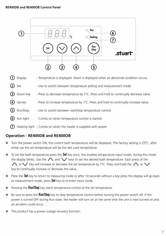
RE400DB and RE400OB Control Panel
1 Display - Temperature is displayed. Alarm is displayed when an abnormal condition occurs.
2 Set - Use to switch between temperature setting and measurement mode.
3 Down key - Press to decrease temperature by 1ºC. Press and hold to continually decrease value.
4 Up key - Press to increase temperature by 1ºC. Press and hold to continually increase value.
5 Run/Stop - Use to switch between start/stop temperature control.
6 Run light - Comes on when temperature control is started.
7 Heating light - Comes on when the heater is supplied with power.
Operation - RE400DB and RE400OB
v Turn the power switch ON, the current bath temperature will be displayed. The factory setting is 25ºC, after
initial use the set temperature will be the last used temperature.
v To set the bath temperature press the Set key once, this enables temperature input mode, during this mode
the display blinks. Use the and keys to set the desired bath temperature. Each press of the
or key will increase or decrease the set temperature by 1ºC. Press and hold the or
key to continually increase or decrease the value.
v Press the Set key to return to measuring mode or after 10 seconds without a key press the display will go back
to measurement mode, press Set key to re-enter input mode.
v Pressing the Run/Stop key starts temperature control at the set temperature.
v Be sure to press the Run/Stop key to stop temperature control before turning the power switch off. If the
power is turned OFF during Run state, the heater will turn on at the same time the unit is next turned on and
an accident could occur.
v This product has a power outage recovery function.
1
432 5
7
6

8
Setting the alarm function - RE400DB and RE400OB
You can set the upper temperature limit alarm or the power outage recovery function .
is the upper temperature limit alarm function.
is the power outage recovery function.
v Press the Set key to switch to measurement mode.
v Hold the Set key for 5 seconds to enter alarm function setting mode, is displayed. press the Up or
Down key to switch between the different alarm functions.
v When you have set the required alarm function, hold the Set key for 5 seconds to return to the measurement mode.
Setting the upper temperature limit alarm - RE400DB and RE400OB
v Ensure that is displayed.
v Press the and key to set the upper temperature limit. Each press of the or key will
increase or decrease the set temperature by 1ºC. Press and hold the or key to continually
increase or decrease the value. Upper temperature limit setting range +10ºC~200ºC. The factory setting is 200ºC.
v Press the Set key to return to alarm function setting mode, the setting of the upper temperature limit alarm is
completed, will be displayed.
v Hold the Set key for 5 seconds to return to the measurement mode.
Setting the power outage recovery function - RE400DB and RE400OB
You can choose whether temperature control will be resumed when power is turned on again after a power
outage by setting the power outage recovery function to or .
, temperature control will resume after the power is restored in the state immediately before the recovery.
, temperature control will stop irrespective of the state before the recovery.
v Ensure that is displayed.
v Press the or key to switch between or . The factory setting is .
CAUTION: If you have set the function to , remember that once power is restored after a power cut the
unit will automatically turn on.
v Press the Set key to return to alarm function setting mode, the setting of the power outage recovery
function is completed, will be displayed.
v Hold the Set key for 5 seconds to return to the measurement mode.
Overheat protector reset procedure - RE400DB and RE400OB
When the overheat protector has been activated the power switch is ON but the display is OFF.
v Turn the power switch OFF.
v Confirm why the overheat protector has been activated (eg bath was heated without oil/water or external
temperature exceeds 35°C) and make sure that the inside of the bath has sufficiently cooled down and
press the ‘RESET’ button on the rear of the unit.
v Turn the power switch ON. The display comes on and temperature control starts. Run light is on.
If it is not possible to reset the overheat protector switch stop operation and contact a local service representative.
9
Maintenance, Servicing and Cleaning
HOT: Before attempting any maintenance, servicing or cleaning, ensure that the unit is cool,
and disconnect from the power supply.
WARNING: Ensure the unit is disconnected from the power supply before attempting any
maintenance, servicing or cleaning.
This product range does not require any routine servicing and there are no servicible parts within the equipment.
The only user maintenance required is the inspection of the power supply unit and mains power lead set.
With proper care and operation, the equipment should give reliable service, however contamination or general
misuse may reduce the effective life of the product and could cause a hazard.
Where used with water, periodically de-scale the bath using a domestic kettle descaler suitable for metal kettles.
Follow the instructions for use supplied with the descaler.
The water bath should be thoroughly rinsed before returning to use. Alternatively use a mild detergent to clean
the bath. Take care not to damage the Teflon coating during cleaning.
WARNING: Observe any cautionary note on the cleaner regarding protective clothing and effluent control.
The exterior of the unit should be cleaned using damp cloth and a mild detergent solution.
Preventative maintenance should include keeping the product clean by protecting it from spillage, contamination
or corrosive environments. If in doubt, please confirm that any intended method of decontamination will not
damage the equipment by contacting Cole-Parmer.
NOTE: Do not use solvents for cleaning any parts of this equipment.
In Case of Accidental Spillage
WARNING: DO NOT TOUCH IF A SPILLAGE/BREAKAGE HAS OCCURRED. DISCONNECT THE
POWER DIRECTLY AT THE POWER SUPPLY SOURCE.
If any part of the equipment other than the bath has been exposed to liquid, it cannot be assumed to meet all
the safety requirements of EN 61010-2-010 until the drying out process has been fully completed and all safety
requirements are met before the unit is used again.
In Case of Contamination
WARNING: THE FOLLOWING PROCEDURE IS INTENDED AS A GUIDE. SHOULD SPILLAGE OF A
TOXIC OR HAZARDOUS FLUID OCCUR, THEN ADDITIONAL SPECIAL PRECAUTIONS MAY
BE NECESSARY.
If the equipment has been exposed to contamination, the Responsible Body is responsible for carrying out
appropriate decontamination. If hazardous material has been spilt on or inside the equipment, decontamination
should only be undertaken under the control of the Responsible Body with due recognition of possible hazards.
Before using any cleaning or decontamination method, the Responsible Body should check with the manufacturer
that the proposed method will not damage the equipment. Prior to further use, the Responsible Body shall check
the electrical safety of the unit. Only if all safety requirements are met can the unit be used again.
NOTE: In the event of this equipment or any part of the unit becoming damaged or requiring service, the item(s)
should be returned to the manufacturer for repair accompanied by a decontamination certificate. Copies of the
Certificate are available from the Distributor/Manufacturer.
At the end of its service life, the product must be accompanied by a Decontamination Certificate.

10
Fuse Replacement
The mains fuse holder is located at the rear of your product. Refer to Electrical Specification (page 11) for correct
fuse type and rating. Turn your unit off and disconnect it from the power supply. Always replace fuses with the
correct type and rating.
Repairs and Support
Any repairs or replacement of parts MUST be undertaken by suitably qualified personnel. Only spare parts supplied
or specified by Cole-Parmer or its agents should be used. Fitting of non-approved parts may affect the performance
and safety features designed into the instrument. For a comprehensive list of parts required by service engineers
conducting internal repairs please contact the service department quoting the model and serial number:
Email: [email protected]
Tel: +44 (0)1785 810475
For any other technical enquiries please contact the Technical Support Department at;
Email: [email protected]
Tel: +44 (0)1785 810433
Warranty
Cole-Parmer Ltd. warrants this instrument to be free from defects in material and workmanship, when used under
normal laboratory conditions, for a period of 3 years. In the event of a justified claim Cole-Parmer will replace any
defective component or replace the unit free of charge. This warranty does NOT apply if damage is caused by fire,
accident, misuse, neglect, incorrect adjustment or repair, damage caused by incorrect installation, adaptation,
modification, fitting of non-approved parts or repair by unauthorised personnel.
Cole-Parmer Ltd,
Beacon Road,
Stone,
Staffordshire,
ST15 0SA,
United Kingdom
Email: [email protected]
Tel: +44 (0)1785 810475
Web: www.stuart-equipment.com
1 2 3 1 2
RE400DB
Remove and replace fuses
Remove and replace fuse
RE400OB
Spare fuse

11
Spares and Accessories
Part No. Description Quantity
HH179(S) UK mains lead moulded plug 230 V - 10A BS1363/A 1
HH180(S) European mains lead moulded plug 230 V 1
Replacement fuses can be ordered by contacting [email protected]. Please refer to Electrical Specification
(page 11) for correct fuse type and rating.
Technical Specification
General Specification RE400DB RE400OB
Safety functions
Overheat preventive device
Fuse
Heat insulation protective bath cover
Self diagnostics function
Bath cover PET (with glass fiber) PBT (with glass fiber)
Bath material SUS304 Aluminium, teflon coating
Bath capacity Approx. 4.3 litres Approx. 5 litres
Size of bath (internal) Ø220 x H120mm Ø240 x H120mm
Container capacity Max. 2 litres Max. 3 litres
External dimensions W285 x D295 x H244mm W282 x D282 x H244mm
Weight 3.9kg 4.5kg
Temperature display range 0°C to 210°C
Display resolution 1°C
Accuracy ± 1°C (during stirring)± 3°C (during stirring) Oil
± 1.5°C (during stirring) Water
Ramp rate Increments of 1°C
Ceiling temperature setting +10°C to 120°C +10°C to 200°C
Display Digital Display
Control Sensor PT sensor
Electrical specification RE400DB RE400OB
Fuse Type T8A 5 x 20 Glass Slow blow
Total power consumption 1400W
Temperature control P.I.D.
Oven operating temperature range Ambient +10°C to 90°CAmbient +5°C to 180°C Oil
Ambient +5°C to 80°C Water
Power supply PSU When ordering a replacement PSU, always quote the instrument’s serial number.
Electricty supply 230 V ~ 50Hz - 6A 230 V ~ 50/60Hz - 6A

12
Weights and Dimensions
295mm
244mm
285mm
244mm
282mm
244mm
282mm
244mm
RE400DB
RE400OB
Weight 3.9kg
Weight 4.5kg

13
Fault Finding
Problem Cause Solution
Display does not work even if the power is switched on.
No mains power. Check mains power supply.
Fuse has blown.Replace the fuse, if fuse blows again immediately stop operation and contact a local service representative.
Overheat protection has tripped either because bath was heated without oil/water or external temperature exceeds 35°C.
Turn off the power switch and allow the unit to cool. Press the rest switch on the back of the unit. Turn the power switch back on. If overheat trips again contact a local service representative.
The power switch is malfunctioning Stop operation and contact a local service representative.
Temperature does not increase. Run light is on and Heating light is off.
Temperature has not been set.
Change the set temperature.Set temperature is below current bath temperature.
Temperature does not increase. Run light is off and Heating light is on.
The Run/Stop key is not pressed. Press the Run/Stop key to start tempera-ture control
Temperatureincreases. Heating light is off.
Set temperature is too low. Set the temperature to 5°C above ambi-ent temperature.
External temperature is too high. Set the temperature to higher than the ambient temperature.
SSR is malfunctioning Stop operation and contact a local service representative.
Temperature does not increase. Heating light is on.
Heater is disconnected, or the terminal of the heater is off.
Stop operation and contact a local service representative.Temperature controller is impaired.
SSR is malfunctioning
Temperature control sensor alarm.
Display shows .
Temperature control sensor has shorted.Stop operation and contact a local service representative.
Temperature control sensor is disconnected.
Upper temperature
limit alarm works.
Display alternates
between and
(liquid
temperature).
Measured value exceeds maximumtemperature.
Check the upper temperature limit. Adjust the liquid and ambient temperature so that the measured temperature will meet the upper temperature limit.
Heater is disconnected, or the terminal of the heater is off.
Stop operation and contact a local service representative.SSR is malfunctioning
Temperature controller is impaired.

14
Lower temperature
limit alarm works.
Display shows .
Ambient temperature is lower than 0°CAdjust the ambient temperature tobetween 5°C and 35°C.
Measured temperature is lower than 0°C
Power outagerecovery alarm. Display alternates
between and
(liquid
temperature).
Differs depending on
the setting.
Power was shut off during temperature control and power was turned on again
Press the Set key to clear display.
Set the temperature control to stop orcontinue during alarm display by setting
or in the power outagerecovery function.
If you can not clear the display with the Set key or or in the power outagerecovery function, stop operation and contact a local service representative.
Display flashes Temperature sensor id disconnected or the terminal of the sensor is off.
Stop operation and contact a local service representative.
15
This product meets the applicable EC harmonized standards for radio frequency interference and may be expected not tointerfere with, or be affected by, other equipment withsimilar qualifications. We cannot be sure that otherequipment used in its vicinity will meet these standards
and so we cannot guarantee that interference will notoccur in practice. Where there is a possibility that injury,damage or loss might occur if equipment malfunctionsdue to radio frequency interference, or for generaladvice before use, contact the manufacturer.
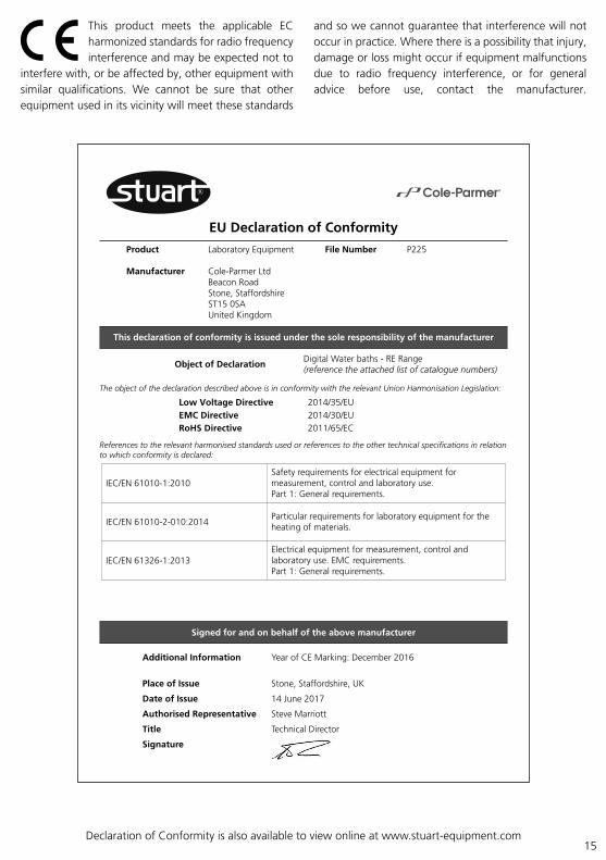
EU Declaration of Conformity
Product Laboratory Equipment
Manufacturer Cole-Parmer Ltd Beacon Road Stone, Staffordshire ST15 0SA United Kingdom
File Number P225
Authorised Cole-ParmerRepresentative Beacon Road Stone, Staffordshire ST15 0SA United Kingdom
Object of DeclarationDigital Water baths - RE Range(reference the attached list of catalogue numbers)
The object of the declaration described above is in conformity with the relevant Union Harmonisation Legislation:
References to the relevant harmonised standards used or references to the other technical specifications in relation to which conformity is declared:
Additional Information
Place of Issue
Date of Issue
Authorised Representative
Title
Signature
This declaration of conformity is issued under the sole responsibility of the manufacturer
Signed for and on behalf of the above manufacturer
Low Voltage DirectiveEMC DirectiveRoHS Directive
2014/35/EU2014/30/EU2011/65/EC
Year of CE Marking: December 2016
Stone, Staffordshire, UK
14 June 2017
Steve Marriott
Technical Director
Electrical equipment for measurement, control andlaboratory use. EMC requirements.Part 1: General requirements (Class A).
IEC/EN 61326-1:2013
IEC/EN 61010-1:2010Safety requirements for electrical equipment formeasurement, control and laboratory use.Part 1: General requirements.
Particular requirements for laboratory equipment for theheating of materials.IEC/EN 61010-2-010:2014
s.
Declaration of Conformity is also available to view online at www.stuart-equipment.com

Cole-Parmer Ltd - UKBeacon Road,Stone,Staffordshire,ST15 0SA,United KingdomTel: +44 (0)1785 812121Email: [email protected]: www.stuart-equipment.com