Embed Size (px)
Citation preview

TD 461-494_2
ESE00364-EN6 2012-01
Original manual
Instruction Manual
Unique Single Seat Valve - Tank Outlet
www.sks-online.com www.sks-webshop.com

www.sks-online.com www.sks-webshop.com
Table of contents
The information herein is correct at the time of issue but may be subject to change without prior notice
1. EC Declaration of Conformity .. . . . . . . . . . . . . . . . . . . . . . . . . . . . . . . . . . . . . . . . . . . . . . . . . . . . . . . . . . . . . . . . . . . . . . 4
2. Safety ... . . . . . . . . . . . . . . . . . . . . . . . . . . . . . . . . . . . . . . . . . . . . . . . . . . . . . . . . . . . . . . . . . . . . . . . . . . . . . . . . . . . . . . . . . . . . . . . . . 52.1. Important information .. . . . . . . . . . . . . . . . . . . . . . . . . . . . . . . . . . . . . . . . . . . . . . . . . . . . . . . . . . . . . . . . . . . . . . . . . . . . 52.2. Warning signs .. .. . . . . . . . . . . . . . . . . . . . . . . . . . . . . . . . . . . . . . . . . . . . . . . . . . . . . . . . . . . . . . . . . . . . . . . . . . . . . . . . . . 52.3. Safety precautions .. . .. . . . . . . . . . . . . . . . . . . . . . . . . . . . . . . . . . . . . . . . . . . . . . . . . . . . . . . . . . . . . . . . . . . . . . . . . . . . 6
3. Installation .. . . . . . . . . . . . . . . . . . . . . . . . . . . . . . . . . . . . . . . . . . . . . . . . . . . . . . . . . . . . . . . . . . . . . . . . . . . . . . . . . . . . . . . . . . . . . 83.1. Unpacking/delivery . . .. . . . . . . . . . . . . . . . . . . . . . . . . . . . . . . . . . . . . . . . . . . . . . . . . . . . . . . . . . . . . . . . . . . . . . . . . . . . 83.2. General installation .. . .. . . . . . . . . . . . . . . . . . . . . . . . . . . . . . . . . . . . . . . . . . . . . . . . . . . . . . . . . . . . . . . . . . . . . . . . . . . . 93.3. Welding .. . . . . . . . . . . . . . . . . . . . . . . . . . . . . . . . . . . . . . . . . . . . . . . . . . . . . . . . . . . . . . . . . . . . . . . . . . . . . . . . . . . . . . . . . . . 103.4. Recycling information .. . . . . . . . . . . . . . . . . . . . . . . . . . . . . . . . . . . . . . . . . . . . . . . . . . . . . . . . . . . . . . . . . . . . . . . . . . . . 11
4. Operation ... . . . . . . . . . . . . . . . . . . . . . . . . . . . . . . . . . . . . . . . . . . . . . . . . . . . . . . . . . . . . . . . . . . . . . . . . . . . . . . . . . . . . . . . . . . . . 124.1. Operation .. .. . . . . . . . . . . . . . . . . . . . . . . . . . . . . . . . . . . . . . . . . . . . . . . . . . . . . . . . . . . . . . . . . . . . . . . . . . . . . . . . . . . . . . . 124.2. Troubleshooting .. . . . . . . . . . . . . . . . . . . . . . . . . . . . . . . . . . . . . . . . . . . . . . . . . . . . . . . . . . . . . . . . . . . . . . . . . . . . . . . . . . 134.3. Recommended cleaning ... . . . . . . . . . . . . . . . . . . . . . . . . . . . . . . . . . . . . . . . . . . . . . . . . . . . . . . . . . . . . . . . . . . . . . . 14
5. Maintenance .. . .. . . . . . . . . . . . . . . . . . . . . . . . . . . . . . . . . . . . . . . . . . . . . . . . . . . . . . . . . . . . . . . . . . . . . . . . . . . . . . . . . . . . . . . 155.1. General maintenance .. . . . . . . . . . . . . . . . . . . . . . . . . . . . . . . . . . . . . . . . . . . . . . . . . . . . . . . . . . . . . . . . . . . . . . . . . . . . 155.2. Dismantling the valve .. . . . . . . . . . . . . . . . . . . . . . . . . . . . . . . . . . . . . . . . . . . . . . . . . . . . . . . . . . . . . . . . . . . . . . . . . . . . 175.3. Plug seal replacement . . . . . . . . . . . . . . . . . . . . . . . . . . . . . . . . . . . . . . . . . . . . . . . . . . . . . . . . . . . . . . . . . . . . . . . . . . . . 175.4. Assembly of valve .. . . . . . . . . . . . . . . . . . . . . . . . . . . . . . . . . . . . . . . . . . . . . . . . . . . . . . . . . . . . . . . . . . . . . . . . . . . . . . . . 185.5. Actuator bushing replacement . . . . . . . . . . . . . . . . . . . . . . . . . . . . . . . . . . . . . . . . . . . . . . . . . . . . . . . . . . . . . . . . . . 185.6. Dismantling of optional maintainable actuator . . . . . . . . . . . . . . . . . . . . . . . . . . . . . . . . . . . . . . . . . . . . . . . . . 185.7. Mounting of optional maintainable actuator . . .. . . . . . . . . . . . . . . . . . . . . . . . . . . . . . . . . . . . . . . . . . . . . . . . . 185.8. Additional equipment .. . . . . . . . . . . . . . . . . . . . . . . . . . . . . . . . . . . . . . . . . . . . . . . . . . . . . . . . . . . . . . . . . . . . . . . . . . . . 19
6. Technical data ... . . . . . . . . . . . . . . . . . . . . . . . . . . . . . . . . . . . . . . . . . . . . . . . . . . . . . . . . . . . . . . . . . . . . . . . . . . . . . . . . . . . . . . 206.1. Technical data .. .. . . . . . . . . . . . . . . . . . . . . . . . . . . . . . . . . . . . . . . . . . . . . . . . . . . . . . . . . . . . . . . . . . . . . . . . . . . . . . . . . . 20
7. Parts list and service kits . . . . . . . . . . . . . . . . . . . . . . . . . . . . . . . . . . . . . . . . . . . . . . . . . . . . . . . . . . . . . . . . . . . . . . . . . . . . 217.1. Drawing .. . . . . . . . . . . . . . . . . . . . . . . . . . . . . . . . . . . . . . . . . . . . . . . . . . . . . . . . . . . . . . . . . . . . . . . . . . . . . . . . . . . . . . . . . . . 217.2. Unique Single Seat Valve - Tank Outlet . .. . . . . . . . . . . . . . . . . . . . . . . . . . . . . . . . . . . . . . . . . . . . . . . . . . . . . . . 227.3. Drawing .. . . . . . . . . . . . . . . . . . . . . . . . . . . . . . . . . . . . . . . . . . . . . . . . . . . . . . . . . . . . . . . . . . . . . . . . . . . . . . . . . . . . . . . . . . . 257.4. Unique Single Seat Valve - Tank Outlet - Reverse Acting .. . .. . . . . . . . . . . . . . . . . . . . . . . . . . . . . . . . . 26
3www.sks-online.com
www.sks-webshop.com

1 EC Declaration of Conformity
The designating company
Alfa LavalCompany Name
Albuen 31, DK-6000 Kolding, DenmarkAddress
+45 79 32 22 00Phone No.
hereby declare that
Unique Single Seat Valve Tank Outlet 29/12-09Denomination Type Year
is in conformity with the following directives:- Machinery Directive 2006/42/EC- Pressure Equipment Directive 97/23/EC category 1 and subjected to assessment procedure Module A.
Manager, Product Centres, CompactHeat Exchangers & Fluid Handling
Bjarne Søndergaard
Title Name
Alfa Laval KoldingCompany Signature
Designation
4 www.sks-online.com www.sks-webshop.com

2 Safety
Unsafe practices and other important information are emphasised in this manual.Warnings are emphasised by means of special signs.
2.1 Important information
Always read the manual before using the valve!
WARNINGIndicates that special procedures must be followed to avoid serious personal injury.
CAUTIONIndicates that special procedures must be followed to avoid damage to the valve.
NOTEIndicates important information to simplify or clarify procedures.
2.2 Warning signs
General warning:
Caustic agents:
5www.sks-online.com www.sks-webshop.com
2 Safety
All warnings in the manual are summarised on this page.Pay special attention to this instructions below so that severe personal injury and/or damage to the valve are avoided.
2.3 Safety precautions
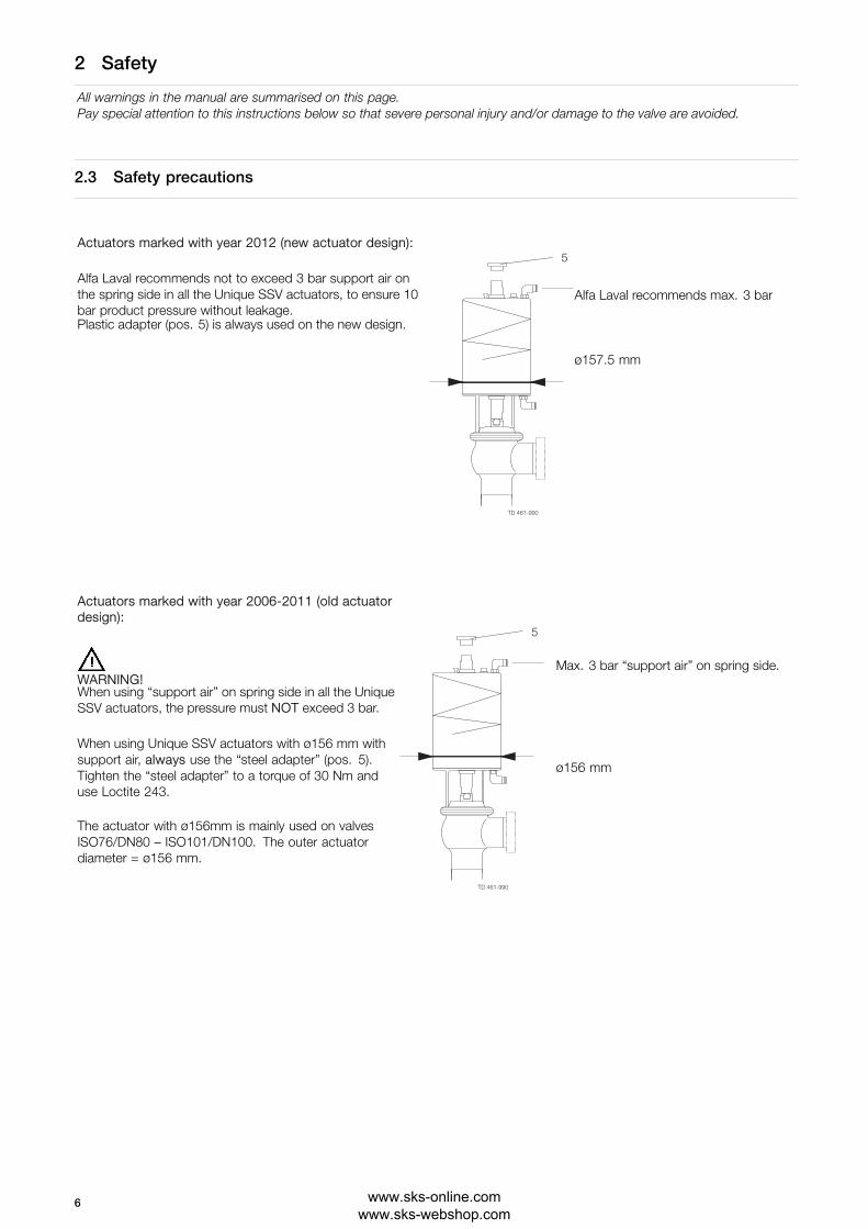
Actuators marked with year 2012 (new actuator design):
Alfa Laval recommends not to exceed 3 bar support air onthe spring side in all the Unique SSV actuators, to ensure 10bar product pressure without leakage.
Alfa Laval recommends max. 3 bar
Plastic adapter (pos. 5) is always used on the new design.
ø157.5 mm
TD 461-990
5
Actuators marked with year 2006-2011 (old actuatordesign):
WARNING!Max. 3 bar “support air” on spring side.
When using “support air” on spring side in all the UniqueSSV actuators, the pressure must NOT exceed 3 bar.
When using Unique SSV actuators with ø156 mm withsupport air, always use the “steel adapter” (pos. 5).Tighten the “steel adapter” to a torque of 30 Nm anduse Loctite 243.
ø156 mm
The actuator with ø156mm is mainly used on valvesISO76/DN80 – ISO101/DN100. The outer actuatordiameter = ø156 mm.
TD 461-990
5
6 www.sks-online.com www.sks-webshop.com

2 Safety
All warnings in the manual are summarised on this page.Pay special attention to this instructions below so that severe personal injury and/or damage to the valve are avoided.
Installation:
Always read the technical data thoroughly (see chapter 6 Technical data).Always release compressed air after useNever touch moving parts if the actuator is supplied with compressed airNever touch the valve or the pipelines when processing hot liquids or when sterilisingNever dismantle the valve with valve and pipelines under pressureNever dismantle the valve when it is hot
Operation:
Never dismantle the valve with valve and pipelines under pressureNever dismantle the valve when it is hotAlways read the technical data thoroughly (see chapter 6 Technical data).Always release compressed air after useNever touch the valve or the pipelines when processing hot liquids or when sterilisingNever touch the moving parts if the actuator is supplied with compressed airAlways rinse well with clean water after the cleaning
Always handle lye and acid with great care
Maintenance:
Always read the technical data thoroughly (see chapter 6 Technical data).Always release compressed air after useNever service the valve when it is hotNever service the valve with valve and pipelines under pressureNever stick your fingers through the valve ports if the actuator is supplied with compressed airNever touch the moving parts if the actuator is supplied with compressed air
Transportation:
Always ensure that compressed air is releasedAlways ensure that all connections are disconnected before attempting to remove the valve from the installationAlways drain liquid out of valves before transportation
Always use predesigned lifting points if definedAlways ensure sufficient fixing of the valve during transportation - if specially designed packaging material is available, itmust be used
7www.sks-online.com www.sks-webshop.com

3 Installation
The instruction manual is part of the delivery. Study the instructions carefully.The items refer to parts list and service kits section.The valve is supplied as separate parts as standard (for welding).The valve is assembled before delivery, if it is supplied with fittings.
3.1 Unpacking/delivery
Step 1CAUTIONAlfa Laval cannot be held responsible for incorrect unpacking.
Check the delivery for:1. Complete valve, standard valve or Reverse Acting valve (RA) (see steps 2a and 2b).2. Delivery note.
Step 2
2aStandard valve:1. Complete actuator.2. Bonnet (20).3. 2 x Clamps (19).4. Valve plug (23).5. Tank flange (40).6. Valve seat (28).7. Valve body (26).
2bReverse Acting valve:1. Complete actuator.2. Bonnet (20).3. 2 x clamps (19).4. Valve plug (23).5. Valve body (26).6. Valve seat (28).7. Tank flange (40).
UP
TD 461-498_1
Step 3Remove possible packing materials from the valve/valve parts.Inspect the valve/valve parts for visible transport damage.Avoid damaging the valve/valve parts.
8 www.sks-online.com www.sks-webshop.com

3 Installation
Study the instructions carefully and pay special attention to the warnings!The valve has welding ends as standard but can also be supplied with fittings.
3.2 General installation
Step 1
Always read the technical data thoroughly.See chapter 6 Technical data.
Always release compressed air after use.
CAUTIONAlfa Laval cannot be held responsible for incorrect installation.
Step 2
Never touch the moving parts if the actuator is supplied withcompressed air.
Moving parts!Air
659
Air
Step 3Avoid stressing the valve.Pay special attention to:- Vibrations.- Thermal expansion of the pipelines.- Excessive welding.- Overloading of the pipelines.
Risk of damage!
9www.sks-online.com www.sks-webshop.com

3 Installation
Study the instructions carefully.The valve is supplied as separate parts to facilitate the welding.The items refer to the parts list and service kits section.Check the valve for smooth operation after welding.
3.3 Welding
Step 1
Before welding the flange into the tank please note:
1. Maintain the minimum clearances “A” to ensure that the actuatorand the internal valve parts can be removed - please see informationlater in this section.
If there is a risk of foot damage, Alfa Laval recommends leavingadistance of 120 mm (4.7”) below the valve (lowest point of actuatorspindle).
A1
TD 449-253
Tank flangeMin. dimension
DN/OD DNSize
51 63.5 76.1 101.6 50 65 80 100
A1 426 439 479 503 429 445 487 506
A1 = Min. installation measure to allow the valve to be lifted out of the tank flange/valve body (if long stroke actuator and/orindication unit is mounted, height must be added).
2. Only use pulsed arc welding and remember no gap betweenflange and tank plate.Tack weld always on the opposite side (8 segments with fillermetal). Weld root if possible without filler metal.Welding of the final run must be carried out in 8 segmentsto avoid cracking.
TD 449-244
4
8
5 1
2 6
7
3
Step 2
Assemble the valve in accordance with the steps on page 18.Pay special attention to the warnings!
10 www.sks-online.com www.sks-webshop.com

3 Installation
Study the instructions carefully.The valve is supplied as separate parts to facilitate the welding.The items refer to the parts list and service kits section.Check the valve for smooth operation after welding.
Step 3Pre-use check:1. Supply compressed air to the actuator.2. Open and close the valve several times to ensure that it
operates smoothly.Pay special attention to the warnings! Open/close Air
AirTD 461-502_1
3.4 Recycling information
• Unpacking
- Packing material consists of wood, plastics, cardboard boxes and in some cases metal straps- Wood and cardboard boxes can be re-used, recycled or used for energy recovery- Plastics should be recycled or burnt at a licensed waste incineration plant- Metal straps should be sent for material recycling
• Maintenance
- During maintenance, oil and wearing parts in the machine are replaced- All metal parts should be sent for material recycling- Worn out or defective electronic parts should be sent to a licensed handler for material recycling- Oil and all non-metal wear parts must be disposed off in agreement with local regulations
• Scrapping
- At end of use, the equipment must be recycled according to the relevant, local regulations. Besides the equipment itself, anyhazardous residues from the process liquid must be considered and dealt with in a proper manner. When in doubt, or in theabsence of local regulations, please contact your local Alfa Laval sales company
11www.sks-online.com www.sks-webshop.com

4 Operation
Study the instructions carefully and pay special attention to the warnings!Ensure that the valve operates smoothly.The items refer to the parts list and service kits section.
4.1 Operation
Step 1
Always read the technical data thoroughly.See chapter 6 Technical data.
Always release compressed air after use.
CAUTIONAlfa Laval cannot be held responsible for incorrectoperation.
Step 2
Never touch the valve or the pipelines when processing hot liquidsor when sterilising.
Danger of burns!
Step 3
Never touch moving parts if the actuator is supplied withcompressed air.
Moving parts! Air
Air
659
Step 4
Lubrication of valves:1. Ensure smooth movement between lip seal (25) and
plug stem (23).2. Lubricate with Klüber Paraliq GTE 703 if necessary
(see page 15).
12 www.sks-online.com www.sks-webshop.com
4 Operation
Pay attention to possible faults. Study the instructions carefully.The items refer to the parts list and service kits section.
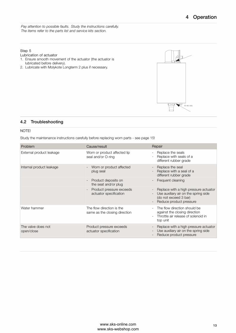
Step 5Lubrication of actuator1. Ensure smooth movement of the actuator (the actuator is
lubricated before delivery).2. Lubricate with Molykote Longterm 2 plus if necessary.
4.2 Troubleshooting
NOTE!
Study the maintenance instructions carefully before replacing worn parts - see page 15!
Problem Cause/result Repair
External product leakage Worn or product affected lipseal and/or O-ring
- Replace the seals- Replace with seals of a
different rubber grade
Internal product leakage - Worn or product affectedplug seal
- Replace the seal- Replace with a seal of a
different rubber grade- Product deposits on
the seat and/or plug- Frequent cleaning
- Product pressure exceedsactuator specification
- Replace with a high pressure actuator- Use auxiliary air on the spring side
(do not exceed 3 bar)- Reduce product pressure
Water hammer The flow direction is thesame as the closing direction
- The flow direction should beagainst the closing direction
- Throttle air release of solenoid intop unit
The valve does notopen/close
Product pressure exceedsactuator specification
- Replace with a high pressure actuator- Use auxiliary air on the spring side- Reduce product pressure
13www.sks-online.com www.sks-webshop.com

4 Operation
The valve is designed for cleaning in place (CIP).Study the instructions carefully and pay special attention to the warnings!NaOH = Caustic Soda.HNO3 = Nitric acid.
4.3 Recommended cleaning
Step 1
Always handle lye and acid with great care.
Caustic danger!
Always userubber gloves!
Always useprotective goggles!
Step 2
Never touch the valve or the pipelines when sterilising.
Danger of burns
Step 3
Shut-off valveClean the plug and the seats correctly.Pay special attention to the warnings!Lift and lower valve plug momentarily.
Step 4Examples of cleaning agents:Use clean water, free from chlorides.
1. 1% by weight NaOH at 70o C 2. 0.5% by weight HNO3 at 70o C
1 kg NaOH + 100 l water = Cleaning agent. 0.7 l53% HNO3
+ 100 l water = Cleaning agent.
2.2 l33% NaOH
+ 100 l water = Cleaning agent.
Step 51. Avoid excessive concentration of the cleaning agent.2. Adjust the cleaning flow to the process.3. Always rinse well with clean water after the cleaning.
NOTEThe cleaning agents must be stored/disposed of in accordancewith current regulations/directives.
Always rinse!
Clean water Cleaning agents
14 www.sks-online.com www.sks-webshop.com

5 Maintenance
Maintain the valve regularly.Study the instructions carefully and pay special attention to the warnings!Always keep spare rubber seals and lip seals in stock.Check the valve for smooth operation after service.
5.1 General maintenance
Step 1
Always read the technical data thoroughly.See chapter 6 Technical data.
Always release compressed air after use.
NOTEAll scrap must be stored/discharged in accordancewith current rules/directives.
Step 2
Never service the valve when it is hot.
Never service the valve with valve and pipelines under pressure.
Atmosphericpressurerequired!
Danger of burns!
Step 3
Never stick your fingers through the valve ports if the actuator issupplied with compressed air.
Air
Danger of cuts!
Air659
Step 4
Never touch the moving parts if the actuator is supplied withcompressed air.
AirMoving parts!
Air659
15www.sks-online.com www.sks-webshop.com

5 Maintenance
Maintain the valve regularly.Study the instructions carefully and pay special attention to the warnings!Always keep spare rubber seals and lip seals in stock.Check the valve for smooth operation after service.
Below are some guidelines for maintenance and lubrication intervals. Please note that the guidelines are for normalworking conditions in one shift.
Product wetted seals Actuator bushings complete
Preventivemaintenance
Replace after12 months dependingon working conditions
Replace after5 years dependingon working conditions
Maintenance afterleakage (leakagenormally starts slowly)
Replace at theend of the day
Replace whenpossible
Plannedmaintenance
- Regular inspectionfor leakage andsmooth operation
- Keep a record ofthe valve
- Use the statistics forinspection planningReplace after leakage
- Regular inspectionfor leakage andsmooth operation
- Keep a record ofthe actuator
- Use the statistics forinspection planningReplace after leakage
Lubrication
Before fittingKlüber Paraliq GTE 703or similar USDA H1approved oil/grease
Before fittingMolykote Longterm 2 plus
Pre-use check:
Open/close! Air
1. Supply compressed air to the actuator.2. Open and close the valve several times to
ensure that it operates smoothly.Pay special attention to the warnings!
TD 461-502_1 Air
Recommended spare partsService kits (see page 21)
16 www.sks-online.com www.sks-webshop.com

5 Maintenance
Study the instructions carefully. The items refer to the parts list and service kits section. Handle scrap correctly.NC = Normally closed.NO = Normally open.A/A = Air/air activated.
5.2 Dismantling the valve
Step 1
1aStandard:1. Supply compressed air to the actuator (only NC).2. Loosen and remove lower clamp.3. Lift away the actuator.4. Release compressed air (only NC).5. Unscrew and remove valve plug.6. Remove O-ring, lip seal and bushing in bonnet.
(Use bushing tool and rubber mallet. See drawing).Note! Be careful not to damage the bushing.
7. Loosen and remove upper clamp.8. Remove valve body.9. Remove seat and O-rings.Pay special attention to the warnings! TD 461-740-1
Note! For plug seal replacement please see page 17.Note!
Be careful not to damage the bushing.
1bReverse Acting:1. Loosen and remove upper clamp.2. Lift away the actuator and valve body.3. Supply compressed air to the actuator (only NC).4. Unscrew and remove valve plug.5. Release compressed air (only NC).6. Remove seat and O-rings.7. Loosen and remove lower clamp.8. Remove valve body.9. Remove O-ring, lip seal and bushing in bonnet.
(Use bushing tool and rubber mallet.See drawing, step 1a).
Note! Be careful not to damage the bushing.
Pay special attention to the warnings!
Note! For plug seal replacement please see page 17.
TD 462-140_1
UP
5.3 Plug seal replacement
1. Remove old seal ring using a knife, screwdriver or similar.Be careful not to damage metal parts.
2. Pre-mount plug seal without pressing it into the groove.3. Squeeze plug seal into the groove using opposite pressure points.4. Release air behind plug seal.Note! For plug seal replacement, please read the instructions in the service kit.
17www.sks-online.com www.sks-webshop.com

5 Maintenance
Study the instructions carefully. The items refer to the parts list and service kits section. Handle scrap correctly.NC = Normally closed.NO = Normally open.A/A = Air/air activated.
5.4 Assembly of valve
Reverse order of 5.2 Dismantling the valve.Lubricate O-ring (21) and lip seal (25) with Klüber Paraliq GTE 703.Remember to tighten spindle and plug to a torque of 30Nm (to use two 17mm spanners).If there are vibrations in the pipeline Alfa Laval recommend using loctite no. 243.
5.5 Actuator bushing replacement
1. Unscrew and remove top and bottom bushings with O-rings.2. Lubricate O-rings with Molykote Longterm 2 plus before fitting.3. Fit bushings and O-rings. Tighten bushingto a torque of 10Nm.
Be careful not to overtighten.
5.6 Dismantling of optional maintainable actuator
1. Rotate cylinder.2. Remove lock wire and pull away cylinder.3. Unscrew nuts and remove yoke.4. Tighten nuts to a torque of 17 Nm.5. Unscrew top and bottom bushings.6. Remove piston with O-ring and spring assembly.7. Remove O-rings and support disc.
Rotate cylinder withservice tool.
Note! The A/A actuator has no spring assembly.
TD 461-033
5.7 Mounting of optional maintainable actuator
Reverse order of 5.6 Dismantling of optional maintainable actuator.Lubricate O-rings (3, 7, 11) with Molykote Longterm 2 plus before fitting.
18 www.sks-online.com www.sks-webshop.com

5 Maintenance
Study the instructions carefully. The items refer to the parts list and service kits section. Handle scrap correctly.NC = Normally closed.NO = Normally open.A/A = Air/air activated.
5.8 Additional equipment
1. Rotate cylinder.2. Remove lock wire and pull away cylinder.3. Reverse piston and spring assembly.4. Reverse adapter, air fitting and plug to opposite end.5. Re-assemble in reverse order (3 to 1).
Pneumatic movementupwards
Pneumatic movementdownwards
19www.sks-online.com www.sks-webshop.com

6 Technical data
It is important to observe the technical data during installation, operation and maintenance.Inform all personnel about the technical data.
6.1 Technical data
Data - valve/actuator
Max. product pressure in pipeline (depends on valve specifications) 1000 kPa (10 bar).
Max. product pressure in tank (depends on valve specifications and temperature) 1000 kPa (10 bar) max. 20o C.
850 kPa (8.5 bar) max. 100o C.
750 kPa (7.5 bar) max. 150o C.
Min. product pressure Full vacuum.
Temperature range -10o C to + 140o C (standard EPDM seal).
Air pressure, actuator 500 to 700 kPa (5 to 7 bar).
Materials - valve/actuator
Product wetted steel parts 1.4404 (316L) (internal Ra < 0.8 µm).
Other steel parts 1.4301 (304).
Plug seal EPDM.
Optional plug seal PTFE (TR2).
Other product wetted seals EPDM (standard).
Optional product wetted seals HNBR and FPM.
Other seals NBR.
NoiseOne metre away from and 1.6 metres above the exhaust the noise level of a valve actuator will be approximately 77db (A) withoutnoise damper and approximately 72 db (A) with damper - measured at 7 bar air-pressure.
20 www.sks-online.com www.sks-webshop.com

7 Parts list and service kits
The drawing shows Unique Single Seat Valve - Tank Outlet.The items refer to the parts list in the following sections.
7.1 Drawing
746
Standard
21www.sks-online.com www.sks-webshop.com

7 Parts list and service kits
The drawing shows Unique Single Seat Valve - Tank Outlet.The items refer to the parts list in the following sections.
7.2 Unique Single Seat Valve - Tank Outlet
TD 461-570_2
22 www.sks-online.com www.sks-webshop.com

7 Parts list and service kits
The drawing shows Unique Single Seat Valve - Tank Outlet.The items refer to the parts list in the following sections.
Parts list
Pos. Qty Denomination
Actuator5 1 Adapter6 2 Bushing7 2 O-ring8 2 O-ring9 1 Plug12 1(2) Air fitting19 2 Clamp20 1 Bonnet21 ♦ 3 O-ring23 1 Plug23.1 1 Plug23.2 ♦ 1 Plug seal24 1 Bushing25 ♦ 1 Lip seal26 1 Valve body28 1 Seat40 1 Tank flange
Service kits
DenominationDN 5051 mm
DN 6563.5 mm
DN 8076.1 mm
DN 100101.6 mm
Service kit for actuator Service kit . . . . . . . . . . . . . . . . . . . . . . . . . . . . . . . . . . . . . . . . . . . . . . . . . . . . . . 9611-92-6500 9611-92-6500 9611-92-6500 9611-92-6500
Service kit for product wetted parts, standard
♦ Service kit, EPDM . . . . . . . . . . . . . . . . . . . . . . . . . . . . . . . . . . . . . . . . . . . . . . 9611-92-6701 9611-92-6702 9611-92-6703 9611-92-6704♦ Service kit, HNBR . . . . . . . . . . . . . . . . . . . . . . . . . . . . . . . . . . . . . . . . . . . . . . 9611-92-6705 9611-92-6706 9611-92-6707 9611-92-6708♦ Service kit, FPM . . . . . . . . . . . . . . . . . . . . . . . . . . . . . . . . . . . . . . . . . . . . . . . . 9611-92-6709 9611-92-6710 9611-92-6711 9611-92-6712
Parts marked with ♦ are included in the service kits.
Recommended spare parts: Service kits.
TD 900-396/1
23www.sks-online.com www.sks-webshop.com

.
24 www.sks-online.com www.sks-webshop.com

7 Parts list and service kits
The drawing shows Unique Single Seat Valve - Tank Outlet - Reverse Acting.The items refer to the parts lists in the following sections
7.3 Drawing
Reverse Acting
25www.sks-online.com www.sks-webshop.com

7 Parts list and service kits
The drawing shows Unique Single Seat Valve - Tank Outlet - Reverse Acting.The items refer to the parts lists in the following sections
7.4 Unique Single Seat Valve - Tank Outlet - Reverse Acting
TD 461-571_7
26 www.sks-online.com www.sks-webshop.com

7 Parts list and service kits
The drawing shows Unique Single Seat Valve - Tank Outlet - Reverse Acting.The items refer to the parts lists in the following sections
Parts list
Pos. Qty Denomination
Actuator5 1 Adapter6 2 Bushing7 2 O-ring8 2 O-ring9 1 Plug12 1(2) Air fitting19 2 Clamp20 1 Bonnet21 ♦ 3 O-ring23 1 Plug23.1 1 Plug23.2 ♦ 1 Plug seal24 1 Bushing25 ♦ 1 Lip seal26 1 Valve body28 1 Seat40 1 Tank flange
Service kits
DenominationDN 5051 mm
DN 6563.5 mm
DN 8076.1 mm
DN 100101.6 mm
Service kit for actuator Service kit . . . . . . . . . . . . . . . . . . . . . . . . . . . . . . . . . . . . . . . . . . . . . . . . . . . . . . 9611-92-6500 9611-92-6500 9611-92-6500 9611-92-6500
Service kit for product wetted parts, standard
♦ Service kit, EPDM . . . . . . . . . . . . . . . . . . . . . . . . . . . . . . . . . . . . . . . . . . . . . . 9611-92-6701 9611-92-6702 9611-92-6703 9611-92-6704♦ Service kit, HNBR . . . . . . . . . . . . . . . . . . . . . . . . . . . . . . . . . . . . . . . . . . . . . . 9611-92-6705 9611-92-6706 9611-92-6707 9611-92-6708♦ Service kit, FPM . . . . . . . . . . . . . . . . . . . . . . . . . . . . . . . . . . . . . . . . . . . . . . . . 9611-92-6709 9611-92-6710 9611-92-6711 9611-92-6712
Parts marked with ♦ are included in the service kits.
Recommended spare parts: Service kits.
TD 900-398/1
27www.sks-online.com www.sks-webshop.com

How to contact Alfa LavalContact details for all countries arecontinually updated on our website.Please visit www.alfalaval.com to access the information directly.
© Alfa Laval Corporate ABThis document and its contents is owned by Alfa Laval Corporate AB and protected by laws governing intellectual property and thereto related rights. It is the responsibility of the user of thisdocument to comply with all applicable intellectual property laws. Without limiting any rights related to this document, no part of this document may be copied, reproduced or transmitted in anyform or by any means (electronic, mechanical, photocopying, recording, or otherwise), or for any purpose, without the expressed permission of Alfa Laval Corporate AB. Alfa Laval Corporate ABwill enforce its rights related to this document to the fullest extent of the law, including the seeking of criminal prosecution.
www.sks-online.com www.sks-webshop.com