Embed Size (px)
Citation preview

ALF150 – User Manual
Sensing Precision Limited. Units 15-16, C.R. Bates Industrial Estate, Wycombe Road, Stokenchurch, Bucks, HP14
3PD. Tel: +44 (0) 1494 363 333 Web: www.sensing-precision.com Email: [email protected]
“…A lightweight, compact unit suitable for all duct leakage testing needs..”
Instruction Manual
ALF150 – User Manual
Sensing Precision Limited. Units 15-16, C.R. Bates Industrial Estate, Wycombe Road, Stokenchurch, Bucks, HP14
3PD. Tel: +44 (0) 1494 363 333 Web: www.sensing-precision.com Email: [email protected]
Contents
Instruction Manual ........................................................................................................................................................ 1
The Air Leakage Finder 150 ........................................................................................................................................... 3
The ALF+ ........................................................................................................................................................................ 3
How It Works ................................................................................................................................................................ 4
The Nozzles ................................................................................................................................................................... 5
The Instrument ............................................................................................................................................................. 6
User Interface ............................................................................................................................................................... 7
Main Menu .................................................................................................................................................................... 7
PID Test Setup Menu (ALF+ ONLY) ................................................................................................................................ 8
Main Test Mode Screen ................................................................................................................................................ 9
PID Test Mode Screen ................................................................................................................................................. 10
Changing the Instruements’ Settings .......................................................................................................................... 11
Data Storage & Streaming........................................................................................................................................... 13
Pre-Test Procedure ..................................................................................................................................................... 14
Procedure for Leakage Testing (Manual Test) ............................................................................................................ 16
Changing Nozzles ........................................................................................................................................................ 16
Routine Maintenance ................................................................................................................................................. 17
Service and Calibration ............................................................................................................................................... 17
Warranty ..................................................................................................................................................................... 17
Performance Curve ..................................................................................................................................................... 19
ALF150 Specification ................................................................................................................................................... 20

ALF150 – User Manual
Sensing Precision Limited. Units 15-16, C.R. Bates Industrial Estate, Wycombe Road, Stokenchurch, Bucks, HP14
3PD. Tel: +44 (0) 1494 363 333 Web: www.sensing-precision.com Email: [email protected]
The Air Leakage Finder 150
The Air Leakage Finder (ALF150) is a low cost, compact, light-weight and self-contained air
measurement instrument based on a fundamental device, ‘The Conical Inlet Nozzle’. It has
been designed for use in the commissioning industry to measure the air tightness of duct
work under both Positive and Negative pressures and allows testing to DW/143, Eurovent
2/2 and SMACNA standards.
The ALF150 is supplied fully calibrated and complete with everything required to carry out a test straight
from the box. With its lightweight, compact design it is suitable for a one man lift and fits neatly in boot of
most small hatchbacks cars.
The menu driven, detachable handheld instrument has been made as intuitive to use as possible and gives
highly accurate, direct readouts of the Test Static Pressure and the Measured Leakage Rate. The test data
can be saved directly to the on-board SD card or streamed via the USB link onto a computer. Virtually no
maintenance of the unit is required and a low cost, low hassle, rapid recalibration service is available.
The ALF+
The ALF+ is the model up from the ALF150. It has the same performance specifications as the ALF150 but
is provided with the following extra facilities:
PID Controlled Automatic Test Mode
K-Type Thermocouple Probe
Barometric Pressure Sensor
The PID test mode will allow the ALF unit to maintain a set test pressure, for a user determined period of
time, and automatically control the fan speed as leaks within the duct are found and sealed up. It will also
inform the user if the duct work meets the required pass criteria by calculating the maximum allowed
leakage rate for the test according to the testing standards used, and the total area of duct being tested.
ALF+ also comes with a K-Type thermocouple temperature sensor and a barometric pressure sensor for
increased flow rate accuracy.

ALF150 – User Manual
Sensing Precision Limited. Units 15-16, C.R. Bates Industrial Estate, Wycombe Road, Stokenchurch, Bucks, HP14
3PD. Tel: +44 (0) 1494 363 333 Web: www.sensing-precision.com Email: [email protected]
How It Works
There are two ways of pressure testing a volume; Positive leakage testing, in which the flexible ducting is
attached to the Outlet side of the fan, allowing the duct to be pressurised. And Negative leakage testing, in
which the flexible ducting is attached to the Inlet side of the fan, allowing the duct to be depressurised.
The pressure displayed on the instrument is the Duct Static Pressure, which is the difference between the
pressure in the duct (measured via the duct adaptor pressure tapping) and atmospheric pressure
(measured within the instrument). The user is able to adjust the fan speed until the predetermined test
static pressure is reached, at which point the leakage rate for that test pressure is displayed.
Any leakage in or out of the volume has to be compensated for by the fan in order to maintain the static
pressure and the user will have to adjust the fan accordingly. The volume flow rate of the fan will therefore
be equal to the leakage rate from the volume of duct under test.
ALF150’s function relies on the rules followed by Conical Inlet Nozzles. These are sited on the fan inlet and
have a defined relationship between the volume flow rate and the pressure developed at the throat of the
nozzle. ALF150’s instrumentation consists of two electronic manometers, one which measures the static
pressure and the other measures the Inlet Nozzle throat pressure. Therefore ALF150 is able to measure
this pressure and calculate the precise Volume Flow rate passing through the selected Conical inlet nozzle
and therefore calculate the precise Leakage Rate.
This then allows an engineer to determine the leakage rate of a volume, locate and seal any leaks and to
monitor the progress as the leaks are sealed. As leaks within the system are located and sealed, the
pressure within the volume will build above the predetermined static pressure, therefore the operator will
have to make adjustments to the fan speed to ensure the static pressure is maintained to the correct level
as the Leakage Rate decreases.

ALF150 – User Manual
Sensing Precision Limited. Units 15-16, C.R. Bates Industrial Estate, Wycombe Road, Stokenchurch, Bucks, HP14
3PD. Tel: +44 (0) 1494 363 333 Web: www.sensing-precision.com Email: [email protected]
The Nozzles
ALF150 comes complete with three
interchangeable Nozzles to cover the full leakage
range of 1l/s to 155l/s.
The ø35mm and ø65mm nozzles comply with ISO
5801:2004 and the ø15mm Nozzle, has been
specifically manufactured to the same
specification, using an orifice plate mass flow
measuring device.
The 65mm nozzle is permanently fixed to the ALF150 and cannot be removed. The 35mm and 15mm are
designed to slot in to the 65mm nozzle when required, which reduces the inlet nozzle size to the required
dimensions. A soft ‘clunk’ indicates the nozzle has been correctly installed.
To remove the 35mm or 15mm nozzle, simply lift them out of the 65mm nozzle.
Ø15mm Nozzle - 1 l/s to 12 l/s
Ø35mm Nozzle - 8 l/s to 70 l/s
Ø65mm Nozzle - 40 l/s to 155 l/s

ALF150 – User Manual
Sensing Precision Limited. Units 15-16, C.R. Bates Industrial Estate, Wycombe Road, Stokenchurch, Bucks, HP14
3PD. Tel: +44 (0) 1494 363 333 Web: www.sensing-precision.com Email: [email protected]
The Instrument
The ALF150 Instrument is powered directly from the AF150 unit itself. It contains an SD card slot and Mini
USB type B port which allows data streaming directly to a computer terminal program.
A separate on / off switch also allows the instrument to be powered down prior to powering the ALF150 unit
down.
A simple 5 button user interface makes using the ALF150 simple and intuitive. See the User Interface
section for more information.
1 KEYPAD
2 USB PORT
3 SD CARD SLOT
4 STATIC PRESSURE TAPPING
5 NEGATIVE PRESSURE TAPPING (Blue)
6 POSITIVE PRESSURE TAPPING (Red)
7 POWER CONNECTOR
8 ON / OFF SWITCH
9 LOCKING PLUNGER
ALF+ Model Only:
The ALF+ is provided with a green k-type
thermocouple port above the ON/OFF switch
for connecting the unit’s thermocouple probe.

ALF150 – User Manual
Sensing Precision Limited. Units 15-16, C.R. Bates Industrial Estate, Wycombe Road, Stokenchurch, Bucks, HP14
3PD. Tel: +44 (0) 1494 363 333 Web: www.sensing-precision.com Email: [email protected]
User Interface
Once the ALF150 has been powered up and the Instrument turned on, it will illuminate with the company
loading screen. After approximately 1 second, the user is presented with the Main Menu.
Main Menu
UP and DOWN are used to navigate through the Main Menu. ENTER is used to confirm a Menu Selection.
When changing units of measure or adjusting the amount of sensor damping etc, a secondary drop down
menu is presented to the user. Choices presented here can again be navigated by pressing UP and DOWN
and confirmed once again by pressing ENTER.
When changing or modifying settings, the UP and DOWN keys are used to make the changes / selection.
ENTER is used to confirm and return to the previous menu. To return to the main menu from a sub menu,
select and confirm “EXIT”.
START / MANUAL MODE Run Main Program
AUTO MODE (ALF+ Only) PID Test Program
SELECT UNITS Change units on display for pressure and flow (Imperial & Metric
available). Also, Select Actual Leakage Rate or Standard Temperature & BP compensated Leakage Rate.
SET TIME / DATE Set time & data
DATA SAVE FREQUENCY Change the data save frequency. (1 Second to 60 Minutes)
AMBIENT SETTINGS Change Temperature & Barometric Pressure
SENSOR DAMPING Change sensor averaging between 0.5 & 6.5 seconds
LANGUAGE Change language (English, French, German & Spanish)

ALF150 – User Manual
Sensing Precision Limited. Units 15-16, C.R. Bates Industrial Estate, Wycombe Road, Stokenchurch, Bucks, HP14
3PD. Tel: +44 (0) 1494 363 333 Web: www.sensing-precision.com Email: [email protected]
PID Test Setup Menu (ALF+ ONLY)
If you select “AUTO MODE”, the user is presented with a test setup menu. This allows the user to
individually change and modify test settings prior to starting a test.
The following options are presented.
SELECT TEST STANDARDS The user can select the test standards to apply to the test. Options
include: Euro - DW/143, U.S – SMACNA or None – Free test. The free test option does not apply any
leakage standards and is only for running a system test. Free test mode can not be used for
commissioning.
SET TARGET & MODE The user can enter the target pressure and select between positive
and negative test modes.
ENTER DUCT AREA The user can enter the total duct area being tested.
SELECT TEST CLASS The user can select the class ductwork being tested.
SET TEST DURATION The user can enter the total test duration. This is presented as a
countdown timer once the duct under test is within the required test criteria for pressure and leakage.
RUN TEST This will initiate the test. The user is asked to confirm the nozzle size
prior to starting the test.

ALF150 – User Manual
Sensing Precision Limited. Units 15-16, C.R. Bates Industrial Estate, Wycombe Road, Stokenchurch, Bucks, HP14
3PD. Tel: +44 (0) 1494 363 333 Web: www.sensing-precision.com Email: [email protected]
Main Test Mode Screen
During operation of the Air Leakage Finder 150, the user is presented with the following screen. It displays
all the information about the test being carried out.
1 PRESSURE READING
2 FLOW RATE READING
ACT = Actual
STP = Standard T&BP Compensated
3 FANSPEED %
4 NOZZLE SIZE
5 DATA LOGGING: ON / OFF
FAN STATUS: ON / OFF
6 TIME
Button Action Operation LEFT Press Changes Nozzles size
RIGHT Press Switch fan On/Off
LEFT and RIGHT Hold Zero the sensor readings
UP or DOWN Press/Hold Increase/decrease fan speed
ENTER Press Switch data logging On/Off.
(Save data if in Manual Mode)
ENTER Hold Return to Main Menu
1 2
3 4
5 6

ALF150 – User Manual
Sensing Precision Limited. Units 15-16, C.R. Bates Industrial Estate, Wycombe Road, Stokenchurch, Bucks, HP14
3PD. Tel: +44 (0) 1494 363 333 Web: www.sensing-precision.com Email: [email protected]
PID Test Mode Screen (ALF+ Only)
During operation of a PID controlled test, the user is presented with the following screen. It displays all the
information about the test being carried out.
To change the nozzle used during the PID test, first pause the test. This brings up the Test Paused Menu
and stops the fan. Select “Change Nozzle” and press ENTER. Now select the nozzle you wish to use for
the test. Press ENTER to confirm. Return to the test by selecting “RESUME TEST”.
From the Test Paused Menu, you can change the nozzle used for the test, view test statistics or quit the
test
Once the test has achieved the target pressure and the flow rate is within the maximum leakage allowed
according to the test standards used, the IN RANGE tab will become highlighted. A countdown down timer
will appear in the bottom right corner, replacing the Fan Speed, and countdown to zero, starting at the
time entered for the Test Duration.
If the SD Card is present, data logging will automatically occur at the frequency specified in the instruments
settings.
1 PRESSURE READING
2 FLOW RATE READING
ACT = Actual
STP = Standard T&BP Compensated
3 TARGET PRESSURE
4 NOZZLE SIZE
5 IN RANGE / NOT IN RANGE
6 FAN SPEED / COUNTDOWN
Button Action Operation
UP or DOWN Press/Hold Increase/decrease Pressure target
ENTER Press Pause Test and Enter Pause Menu
1 2
3 4
5 6

ALF150 – User Manual
Sensing Precision Limited. Units 15-16, C.R. Bates Industrial Estate, Wycombe Road, Stokenchurch, Bucks, HP14
3PD. Tel: +44 (0) 1494 363 333 Web: www.sensing-precision.com Email: [email protected]
Changing the Instruements’ Settings
The below settings apply to both the Manual and Automatic test modes.
Select Units
Select Units allows lets you choose your desired units for Pressure and Flow rate. Use the UP and DOWN key to select Pressure, Flow or Flow Correction, then press ENTER to confirm. Select your units of choice and press ENTER to confirm. Flow Correction can be On or Off. Switch Flow Correction ON to correct flow rate to standard conditions.
Set Time & Date
Set Time & Date allows the user to adjust the time and date. Once set, these setting will be indefinitely saved. Navigate through the time and date fields with the LEFT & RIGHT keys. Use UP & DOWN to change the value in that field. Press ENTER to confirm to save the Time & Data and return to the main menu.
Note: ALF150 automatically corrects for leap years and auto calculates the correct day of the week for the specific date set by the user. It does not currently account for day light savings.
Data Save Frequency
Data Save Frequency allows a user to change the frequency at which data is auto logged during a test The highest selectable frequency is once per second, with lowest frequency being once every hour. Once the frequency reaches 60 seconds the value will increase in increments of 1 minute only. Use UP & DOWN to adjust the data save frequency. Press ENTER to confirm.
Ambient Settings
Ambient Settings allows the user to adjust the ambient temperature and barometric pressure to suit their test location. Doing this ensures maximum accuracy when conducting a test. Use the UP and DOWN Key to select Temperature or Pressure. Press ENTER to confirm. Now use the UP and DOWN keys to modify the temperature / pressure. Press ENTER to confirm.
ALF+ Only:
Modifying the temperature or pressure will override the onboard sensors and the air density will be calculated using the temperature and pressure specified by the user.
Pressing LEFT while adjusting the temperature or pressure will force the instrument to update the temperature and barometric pressure by reading the onboard sensors.

ALF150 – User Manual
Sensing Precision Limited. Units 15-16, C.R. Bates Industrial Estate, Wycombe Road, Stokenchurch, Bucks, HP14
3PD. Tel: +44 (0) 1494 363 333 Web: www.sensing-precision.com Email: [email protected]
Sensor Damping
Sensor Damping allows the user to adjust the response of the onboard sensors. Decreasing the damping tolerance to 1 will provide a true instantaneous reading. Increasing the damping tolerance up to 15 will provide and averaged reading up to a maximum of 6.5 seconds. Use UP & DOWN to select either the Pressure Sensor or Flow Sensor. Press ENTER to confirm. User UP and DOWN to modify the sensor damping levels. Press ENTER to confirm.
Note: In both tolerance settings, the range is 1 to 15. The lower the number the truer the reading will be to the instantaneous reading and it will appear less stable. The higher the number the more of an average it will be and it will appear more stable. Adjust the damping tolerance to suit your test requirements.
Language
Language allows a user to change the language in which data is displayed. Choose your language by using the UP and DOWN key and presses ENTER to confirm. You can choose between English, French, German and Spanish.

ALF150 – User Manual
Sensing Precision Limited. Units 15-16, C.R. Bates Industrial Estate, Wycombe Road, Stokenchurch, Bucks, HP14
3PD. Tel: +44 (0) 1494 363 333 Web: www.sensing-precision.com Email: [email protected]
Data Storage & Streaming
Data Logging allows the user to save the data from a test in real time to the SD card, at a predetermined
interval period set by the user. This data is also streamed via the USB port to a computer with access to a
terminal program, allowing the user to simply copy the data to a program where it can be formatted. The
data saved on the SD card is in a .CSV format, and can be opened and edited in a spreadsheet program.
Manual Data Logging functions in the same way as Data Logging, only, the user has to manually save the
data as and when required by pressing the ENTER key on the keypad. This allows the user to snapshot
save data rather than continuously save data.
Each test report stored on the SD card contains the relevant test information such as the date, time,
ambient temperature, ambient barometric pressure as well as the test data itself. Each report is numbered
sequentially and is stored in chronological folder system.
The save directory is as follows: LOGS/MONTH/DAY/test.CSV
For example, test number 36 on the 6th August 2015 is located in the following location:
“LOGS/AUG/6/0036.CSV”
The test data recorded is as follows;
Time, Static Pressure, Leakage Rate, Fan speed, Nozzle size
The User can stream data from the instrument by using the USB port to connect the instrument to a
computer. Using a suitable terminal program, the user can select the COM port assigned to the instrument
when connected and open a terminal window to view the data in real time.
To establish a serial connection:
Identify the COM port assigned to the instrument. I.E COM6. This can be found using Device
Manager on the computer Set the BAUD rate to 115200 Initiate a new serial connection
If successful, the terminal window will display the instrument settings and serial number at start up. Data
will automatically be displayed in real time at the same update interval as the data log frequency during a
test.

ALF150 – User Manual
Sensing Precision Limited. Units 15-16, C.R. Bates Industrial Estate, Wycombe Road, Stokenchurch, Bucks, HP14
3PD. Tel: +44 (0) 1494 363 333 Web: www.sensing-precision.com Email: [email protected]
Pre-Test Procedure
Connect the ALF 150 to the correct power supply using the power lead supplied.
Move the ALF150 into position so that it can be setup with little risk of personnel tripping over the duct,
cables or tubes during testing.
For best performance, position the ALF150 so the flexible duct is as straight as possible.
Connect the flexi ducting to the fan inlet (Negative testing) or the outlet (Positive testing) and secure in
place with toggle clamps.

ALF150 – User Manual
Sensing Precision Limited. Units 15-16, C.R. Bates Industrial Estate, Wycombe Road, Stokenchurch, Bucks, HP14
3PD. Tel: +44 (0) 1494 363 333 Web: www.sensing-precision.com Email: [email protected]
Securely fix the duct adaptor plate to the ductwork.
Ensure the duct length to be tested is sealed off where appropriate.
Connect the duct pressure tapping to the instrument pressure tapping.
If the static pressure tapping on the duct adapter does not fit within the duct, an additional pressure tapping
on the duct will be required.
The system is now ready to implement the Procedure for Leakage Testing.
ALF150 – User Manual
Sensing Precision Limited. Units 15-16, C.R. Bates Industrial Estate, Wycombe Road, Stokenchurch, Bucks, HP14
3PD. Tel: +44 (0) 1494 363 333 Web: www.sensing-precision.com Email: [email protected]
WARNING: When in Negative Test Mode ALF150 is capable of generating 2500 Pa of
Pressure. Please take care when testing duct work under negative pressure.
1.1 Turn the fan to OFF via the instrument.
1.2 Wait for the fan to become stationary.
WARNING: Do not change nozzles with the fan running.
1.3 Negative Mode Only – Unclip and remove flexi duct adaptor from fan inlet.
1.4 Remove the in situ nozzle, if present and place in nozzle storage box.
1.5 Insert replacement or use fixed nozzle.
1.6 Negative Mode Only – Reattach flexi duct to fan inlet.
1.7 Zero the instrument before the fan is turned back on.
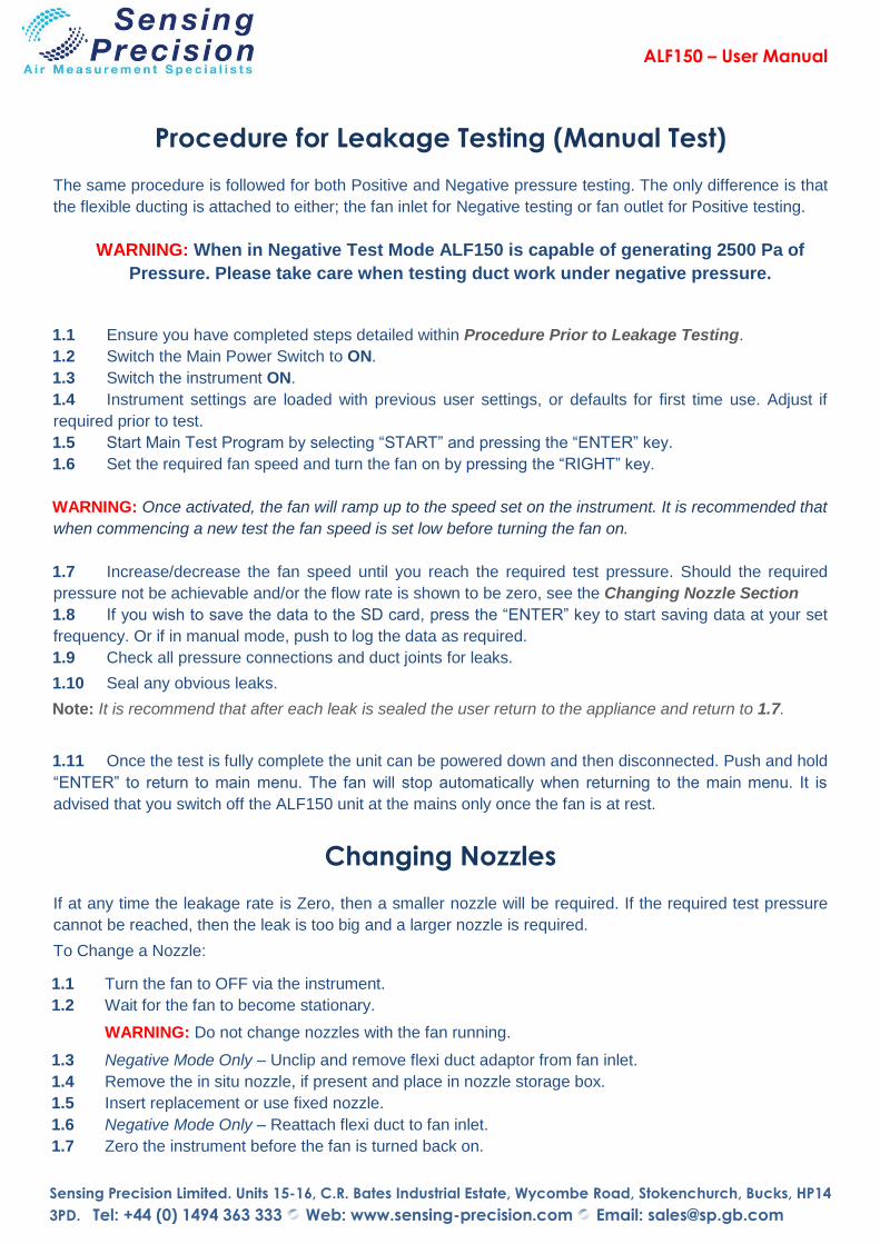
Procedure for Leakage Testing (Manual Test)
The same procedure is followed for both Positive and Negative pressure testing. The only difference is that
the flexible ducting is attached to either; the fan inlet for Negative testing or fan outlet for Positive testing.
1.1 Ensure you have completed steps detailed within Procedure Prior to Leakage Testing.
1.2 Switch the Main Power Switch to ON.
1.3 Switch the instrument ON.
1.4 Instrument settings are loaded with previous user settings, or defaults for first time use. Adjust if
required prior to test.
1.5 Start Main Test Program by selecting “START” and pressing the “ENTER” key.
1.6 Set the required fan speed and turn the fan on by pressing the “RIGHT” key.
WARNING: Once activated, the fan will ramp up to the speed set on the instrument. It is recommended that
when commencing a new test the fan speed is set low before turning the fan on.
1.7 Increase/decrease the fan speed until you reach the required test pressure. Should the required
pressure not be achievable and/or the flow rate is shown to be zero, see the Changing Nozzle Section
1.8 If you wish to save the data to the SD card, press the “ENTER” key to start saving data at your set
frequency. Or if in manual mode, push to log the data as required.
1.9 Check all pressure connections and duct joints for leaks.
1.10 Seal any obvious leaks.
Note: It is recommend that after each leak is sealed the user return to the appliance and return to 1.7.
1.11 Once the test is fully complete the unit can be powered down and then disconnected. Push and hold
“ENTER” to return to main menu. The fan will stop automatically when returning to the main menu. It is
advised that you switch off the ALF150 unit at the mains only once the fan is at rest.
Changing Nozzles
If at any time the leakage rate is Zero, then a smaller nozzle will be required. If the required test pressure
cannot be reached, then the leak is too big and a larger nozzle is required.
To Change a Nozzle:

ALF150 – User Manual
Sensing Precision Limited. Units 15-16, C.R. Bates Industrial Estate, Wycombe Road, Stokenchurch, Bucks, HP14
3PD. Tel: +44 (0) 1494 363 333 Web: www.sensing-precision.com Email: [email protected]
Routine Maintenance
Routine Checks:
Check the flexible hose for rips and tears and that it is securely connected to both the duct adaptors and hose coupling.
Check integrity of pressure tubes and their connections to the instrument and nozzle tappings.
Check power lead for damage
Check nozzles for dents, chips and large scratches.
Check O-rings for damage and ensure they are thoroughly lubricated.
Replace components as necessary – Spares available from [email protected] or +44 (0) 1494 363 333.
Service and Calibration
Instrument Pod:
The Instrument Pod should be returned to Sensing Precision annually for calibration.
To obtain a quotation to order against please email: [email protected]
Nozzles:
The nozzles are designed and checked against a primary standard at manufacture and therefore they do not require calibration. They should be inspected regularly for any damage as this may affect their performance.
If you are concerned about the integrity of the Ø35mm or Ø15mm replacement nozzles are available from [email protected].
For the Ø65mm fixed nozzle please refer to the Full Unit service section.
Full Unit:
Should the full unit develop fault or be damaged the unit can be returned to us for servicing and
repair.
It is recommended that the full unit is returned to us every 3 years for a full inspection and service.
Please contact [email protected] before returning your unit!
Warranty
The product is supplied with a two year limited warranty against manufacturing defects and component failure but excludes damage caused through misuse, repair of which will be quoted prior to commencement of work. The warranty is also subject to the recommended service and calibration schedule being followed.
Please contact [email protected] before returning your unit for service or repair & to order Spare
Parts.

ALF150 – User Manual
Sensing Precision Limited. Units 15-16, C.R. Bates Industrial Estate, Wycombe Road, Stokenchurch, Bucks, HP14
3PD. Tel: +44 (0) 1494 363 333 Web: www.sensing-precision.com Email: [email protected]
Electrical Safety:
Both active components within the main unit are internally fused with a non-replaceable device.
Should incorrect voltage/spikes be applied to the unit or another event occurs that causes a fuse to blow, please contact us to arrange repair/replacement of the affected parts.
No user serviceable parts are contained within the unit and all servicing should be referred to the manufacturer as many connections inside the unit could be at mains potential.
Electrical cable should be checked regularly for damage and replaced if insulation or plugs/sockets are damaged.
For optimum safety the unit should be used on an RCD/Earth Leakage protected circuit as well as a sensibly sized over current trip.

ALF150 – User Manual
Sensing Precision Limited. Units 15-16, C.R. Bates Industrial Estate, Wycombe Road, Stokenchurch, Bucks, HP14
3PD. Tel: +44 (0) 1494 363 333 Web: www.sensing-precision.com Email: [email protected]
Performance Curve

ALF150 – User Manual
Sensing Precision Limited. Units 15-16, C.R. Bates Industrial Estate, Wycombe Road, Stokenchurch, Bucks, HP14
3PD. Tel: +44 (0) 1494 363 333 Web: www.sensing-precision.com Email: [email protected]
ALF150 Specification
Volume Flow Measurement 1 l/s to 150 l/s over nozzle ranges
Pressure Measurement Range ± 2500 Pa
Typical Duty Points 70 l/s at 2000Pa, 140 l/s at 500Pa
Pressure Measurement
Accuracy ± 1% of reading ± 1 digit
Leakage Flow Accuracy ± 2.5% of reading ± 1 digit
Resolution 1Pa
Power 400W
Voltage 230Vac 50/60Hz (or 115Vac 50/60Hz
available)
Unit Size 35 (W) x 46 (D) x 80 (H) cm
Unit Weight 20kg
Carry Case (c/w Accessories)
Size 45 (W) x 45 (D) x 55 (H) cm
Carry Case (c/w Accessories)
Weight 10.5kg
Clip on Trolley Size 38 (W) x 20 (D) x 94 (H) cm
Clip on Trolley Weight 6.7kg

ALF150 – User Manual
Sensing Precision Limited. Units 15-16, C.R. Bates Industrial Estate, Wycombe Road, Stokenchurch, Bucks, HP14
3PD. Tel: +44 (0) 1494 363 333 Web: www.sensing-precision.com Email: [email protected]
Notes:

ALF150 – User Manual
Sensing Precision Limited. Units 15-16, C.R. Bates Industrial Estate, Wycombe Road, Stokenchurch, Bucks, HP14
3PD. Tel: +44 (0) 1494 363 333 Web: www.sensing-precision.com Email: [email protected]
Sensing Precision Limited
Units 15-16, C.R. Bates Industrial Estate,
Wycombe Road, Stokenchurch,
High Wycombe,
Buckingham
United Kingdom
HP14 3PD
Tel: +44 (0) 1494 363 333
Web: www. sensing-precision.com
Email: [email protected]
Registered in England No. 07878150
Rev 1.4 – 04.2016 - E&OE - Data subject to change after final testing - Copyright © 2014 Sensing Precision Limited – Prt. No. 3100002