Embed Size (px)
Citation preview
Instruction Manual
RK-1500Q-NP5

2
CONTENTS
Safety Page 3 Specifications Page 3 Preparing the tool for service Page 4 Air supply Page 4 Maintenance
Daily Page 5 Weekly Page 6 Monthly Page 7 Trigger Service Page 8
Assembly Drawings Schematic Addendum A Parts List Addendum B
MSDS Page 10 Troubleshooting Warranty
Page 12
Page 13

3
SAFETY DO NOT USE OUTSIDE DEISNG INTENT OR WITH EQUIPMENT THAT IS NOT RECOMMENDED BY THE MANUFACTURER.
ALWAYS DISCONNECT THE AIR SUPPLY BEFORE ATTEMPTING ANY MAINTENANCE OR ADJUSTMENT/FITTING OF NOSE EQUIPMENT
DO NOT OPERATE A TOOL THAT IS DIRECTED TOWARDS ANY PERSON(S) OR WITH THE NOSE PIECES OFF THE TOOL
ALL MODIFICATIONS CARRIED OUT ON THE TOOL WITHOUT EXPRESS WRITTEN CONSENT OF THE MANUFACTURER SHALL BE DONE
SO AT THE CUSTOMERS’ SOLE RESPONSIBILITY
REFER TO THIS MANUAL BEFORE ATTEMPTING ANY MAINTENANCE OPERATION. DO NOT DISASSEMBLE THIS TOOL BEFORE
RFERING TO THIS MANUAL.
AVOID EXCESSIVE CONTACT WITH HYDRAULIC OIL, AS SOON AS POSSIBLE WASH HANDS THOROUGHLY
DO NOT EXCEED 6 BAR / 90 PSI INLET PRESSURE, THE USE OF A PRESSURE REGULATOR IS HIGHLY RECOMMENDED
INSPECT THE TOOL USING PREVENTITIVE MAINTENANCE TECHNIQUES AT REUGULARLY SCHEDULED INTERVALS. INSPECT FOR
DAMAGE AND FUNCTION BY TRAINED COMPETANT PERSONEL. THE PLASTIC BODY MUST BE CHANGED WHERNEVER THERE IS
EVIDANEC OF IMPACT DAMAGE, CHIPPING, OR CRACKING.
WEAR SAFETY GLASSES AND ADOPT FIRM FOOTING DURING OPERATION.
SPECIFICATIONS The specifications and information contained in this manual are applicable only to the tool with which it was supplied. Industrial Rivet & Fastener Co reserve the right to make any changes without notice as part of Industrial Rivet & Fastener Co policy of continuous improvement.
SPECIFICATIONS RIVET NUT TOOL
Air Pressure Min/Max □ 5.5 – 6 bar □ 80-90 psi Free Air Volume Required @5.5 bar/75psi □ 4.3 liters □
The Tool Come With NP8 □ 5/16-18 Nose Set □ All materials Purchased Separately NP6 □ ¼-20 Nose Set □ All materials

4
PREPARING THE TOOL FOR SERVICE
111... Inspect for damage 222... Connect the tool to the air supply 333... Insure the Rivet Nut you wish to install is within the capacity of the rivet tool 444... Choose and securely install the applicable nose piece for the rivet nuts you wish to apply. 555... Bring the tool and the rivet into the application hole. Insure the rivet head flat onto surface 666... Fully actuate the rocker trigger. The top button will spin the rivetnut onto the mandrel and
install the rivetnut into the workpiece. The lower button will spin the rivetnut off the mandrel.
JAMMED GUN REMEDY
1. Disconnect tool from air supply 2. Remove Nose Piece 3. Replace Mandrel if Necessary 4. Reapply the nose case securely to the tool 5. Reattach air supply. Actuate tool without rivet. Check Function. 6. Once comfortable, Apply Rivets nuts.
AIR SUPPLY
The rivet tool is powered by compressed air at an optimum pressure of 5.5-6.0bar(80-90 psi)
The use of a pressure regulator filter/lubricator unit within 3 meters of the tool is highly recommended to extend the life of the tool.
Dirt and/or water in the air supply can seriously impact the performance and durability of the tool; damage to the tool caused by contaminated air supply is not covered under warranty
5
MAINTENANCE In order to maintain the tool in a safe working order it is important to carry out regular maintenance as prescribed by the manufacturer. A thorough inspection replacement of all seals within the tool should be carried out after 500,000 placings or annually, whichever is the sooner. Item numbers in parentheses refer to assembly drawing part numbers
Daily Maintenance
Check for air leaks. Any damaged hoses should be replaced
Lubricate the tool by pouring a few drops of light lubricating oil into the air inlet on the tool
If there is no pressure regulator, bleed the airline to clear it of accumulated dirt or water before connecting the air hose to the tool. If there is a filter, drain it.
Check for proper nose piece/mandrel use depending on the size of the rivet nut.
Remove the mandrel from the front nose assembly and inspect for cracks, wear or other damage. Replace if necessary.
Check that front nose assembly is fully tightened onto body
6
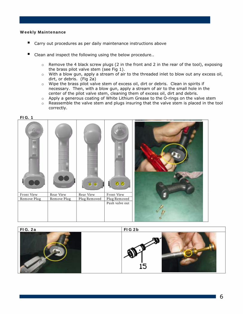
Weekly Maintenance
Carry out procedures as per daily maintenance instructions above
Clean and inspect the following using the below procedure..
o Remove the 4 black screw plugs (2 in the front and 2 in the rear of the tool), exposing the brass pilot valve stem (see Fig 1).
o With a blow gun, apply a stream of air to the threaded inlet to blow out any excess oil, dirt, or debris. (Fig 2a)
o Wipe the brass pilot valve stem of excess oil, dirt or debris. Clean in spirits if necessary. Then, with a blow gun, apply a stream of air to the small hole in the center of the pilot valve stem, cleaning them of excess oil, dirt and debris.
o Apply a generous coating of White Lithium Grease to the O-rings on the valve stem o Reassemble the valve stem and plugs insuring that the valve stem is placed in the tool
correctly. FIG. 1
Front View Rear View Rear View Front View Remove Plug Remove Plug Plug Removed Plug Removed Push valve out
FIG. 2a FIG 2b

7
Monthly Maintenance
Carry out procedures as per daily & monthly maintenance instructions above
Grease the engine/gear reducer with a red synthetic grease

8
Trigger Service
Inspect trigger pin valve by insuring 56 has not come loose. The proper depth should be just under the valve stem.
If adjustment is necessarym using a fork wrench or tire valve tool, screw the trigger pin 56 into the valve stem. A very small amount of loctite243 is ok around the threaded portion only.
If the trigger still fails, remove the trigger pin assembly from the valve stem and inspect the seal around the trigger pin for damage. If damaged, purchase a replacement part. Re-assemble according to the previous step.
#55 & #56

RK-1500Q-NP5 AIR RIVET NUT TOOL
RK-1500Q-NP5 AIR RIVET NUT TOOL TECHNICAL DATA
Capacity: Free Speed Avg. Air Consumption Operating Air Pressure Net Weight Air Inlet Hose Size (I.D.) Length Sound pressure
:::::::::
#10-32 rivet nut in all materials 1.500 RPM 9.9cfm (280 1/min) 90 PSI (6.2 Bar) 1.2 kgs 1/4” NPT/PT 3/8” (9.5mm) I.D. 191 mm 95 DBA
P A R T S L I S T Index Part # Description Index Part # Description Index Part # Description 1L
1R 1A 1B 3. 4A 4B 5. 6. 7. 8. 9. 10. 11. 12. 13. 14. 15. 16. 17. 18.
180101L-B 180101R-B 180704 180714 040725 040713 NN0407B 107602 107601 612714 612717 612711 180703S 180703L 461201 OR0408 919202 OR0711 OR1014 107409 180202
Housing-L Housing-R Muffler material Muffler material Screw Screw (4) Throttle lever nut(5) Valve Body (2) Bleeding Valve (2) Washer (4) Socket (Lower) (4) Cap (4) 2x4xL:48 Air Hose-S 2x4xL:79 Air Hose-L Valve O-RING (4) Valve Steam (2) O-RING (6) O-RING (5) Inlet Plug (5) Hose Connector S (2)
19. 21. 22. 23. 26. 27. 28. 29. 31. 32. 33. 34. 35. 36. 37. 38. 39. 40. 41.
OR0306 180702 180201 461601 108102 320101 SP2514 B20626 320302 320301 320305 320304 106303 B26902 208501 HK0810 RP4015 320502 106506
O-RING (2) 6x8xL:130 Air Hose (2) Hose Connector Y (2)Butterfly Trigger Lock Nut Motor housing Spring Pin Ball Bearing End Plate Cylinder Rotor Blade (6) Rotor Front Plate Ball Bearing Internal Gear Needle Bearing Pin (2) Planet Gear (2) Planet cage
42. 44. 45. 46. 47. 48. 49. 50. 55. 56. 57. 58. 59. 60. 61.
B26001 RP2005 208115 SB0039 208117 208118 208119 RS3032 208507 132801 S103238 105802 106803 T21024 132814
Ball Bearing Pin Q-Chang Clamp Steel Ball Q-Chang Clamp Spring Washer Ring Spring Hexagon Bit #10-32 Bolt #10-32 Bushing #5 Washer Thrust Bearing NTB1024 Nut Anvil #10-32
9
SCHEMATIC Please see the attached document for the parts drawing & parts list.
PARTS LIST
Please see the attached document for the parts drawing & parts list.
Oil Details The recommended oil for priming is Hyspin VG32 available in 0.51 or one gallon containers, or, you can use 30W hydraulic oil. Please see safety data below. Hyspin VG 32 Oil Safety Data First Aid SKIN: Wash thoroughly with soap and water as soon as possible. Casual or short term contact requires no immediate attention. INGESTION: Seek medical attention immediately. DO NOT induce vomiting. EYES: Irrigate immediately with water for several minutes. Although NOT a primary irritant, minor irritation may occur following contact. Fire Flash point 232°C. Not classified as flammable. Suitable extinguishing media: CO2, dry powder, foam or water fog. DO NOT use water jets. Environment WASTE DISPOSAL: Through authorized contractor to a licensed site. May be incinerated. Used product may be sent for reclamation. SPILLAGE: Prevent entry into drains, sewers, and water courses. Soak up with absorbent material. Handling Wear eye protection, impervious gloves (e.g. of PVC) and a plastic apron. Use in well ventilated area. Storage No special precautions.
10
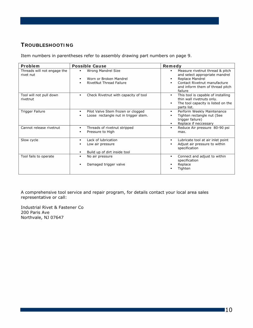
TROUBLESHOOTING Item numbers in parentheses refer to assembly drawing part numbers on page 9. Problem Possible Cause Remedy Threads will not engage the rivet nut
Wrong Mandrel Size Worn or Broken Mandrel RivetNut Thread Failure
Measure rivetnut thread & pitch and select appropriate mandrel
Replace Mandrel Contact Rivetnut manufacture
and inform them of thread pitch failure
Tool will not pull down rivetnut
Check Rivetnut with capacity of tool
This tool is capable of installing thin wall rivetnuts only.
The tool capacity is listed on the parts list.
Trigger Failure Pilot Valve Stem frozen or clogged Loose rectangle nut in trigger stem.
Perform Weekly Maintenance Tighten rectangle nut (See
trigger failure) Replace if neccessary
Cannot release rivetnut Threads of rivetnut stripped Pressure to High
Reduce Air pressure 80-90 psi max.
Slow cycle Lack of lubrication Low air pressure Build up of dirt inside tool
Lubricate tool at air inlet point Adjust air pressure to within
specification
Tool fails to operate No air pressure Damaged trigger valve
Connect and adjust to within specification
Replace Tighten
A comprehensive tool service and repair program, for details contact your local area sales representative or call: Industrial Rivet & Fastener Co 200 Paris Ave Northvale, NJ 07647

11
Warranty Statement: Industrial Rivet & Fastener Co. Inc. and Zipp Tools (hereinafter “IRF”), hereby warrants to the initial retail customer and original distributor (“Warrantee”) only that its products will be free from defects in material and workmanship for a period of 1 year from the purchase date, provided that the products are used in accordance with “IRF’s” instructions as to maintenance, operation and use. The said warranty does not extend to goods subjected to misuse, neglect, accident or improper installation or maintenance or which have been altered or repaired by anyone other than the seller or its authorized agents. The warrantee’s only remedy and IRF’s only obligation in the event of a defect or failure in the products, is that IRF, at its sole option, repair, replace or rework the products, but in no case shall the cost of the foregoing exceed the invoice price of the products. This warranty shall be void if any person seeking to make a claim for defective or failed products fails to notify IRF within 30 days of receipt of evidence that the product is defective or has failed, or if said person fails to provide IRF with such evidence as is reasonably requested concerning the effect or failure, including without limitation, evidence of the date of purchase and date of installation. This warranty is in lieu of all other warranties, expressed or implied, including merchantability, or fitness provided for herein. Under no circumstance shall IRF be liable for incidental or consequential damages arising from the defect or failure in its products. Seller’s sole obligation under the foregoing warranty will be limited to, at Seller’s option, repair or replacement of the tool (and shipping to the buyer with transportation charges paid to any place within the contiguous 48 states). Returned goods will be evaluated by our warranty repair department and a conclusion will be determined and classified as:
a) Warranty Repair (free of charge) b) Abuse /Neglect (bench fee and/or hourly rate) c) Maintenance (Flat Fee)
If inspection by the seller of returned goods shows no breach of the forgoing warranty, Seller’s regular conditioning charges (as stated above) apply. Upon this conclusion we will either repair the tool at no cost to you and return it postage paid, or call you to inform you of the repair cost. The repair will need to be approved in writing before any work is performed. A comprehensive tool service and repair program, for details contact your local area sales representative or call: Industrial Rivet & Fastener Co. 200 Paris Ave Northvale, NJ 07647 1-800-BUY-RIVET