Embed Size (px)
Citation preview

ManualPart No. 95180 5-31-07
MP30Draw Down Meter
MODEL
PATENT PENDING
OUasics
Instruction
P.O. Box 3726 Ann Arbor, MI 48106-3726 USA1-800-624-2026 Fax (734) [email protected] www.qedenv.com


CONTENTS
Topic
MP30 Cable connection
Drawdown Control Point Selection
Equipment Check
General
Specifications
QED Service Contacts
Cleaning the Meter
Page
1
1
1
2
3
5
5
5
3
4
4
6
7
7
8
MP 30 Operating Instructions
Background
Drawdown Control Quick Guide
Drawdown Control Response with MicroPurge basics controllers
General Information on MP30 Features and Usage
Use in the Field- Static Water Level Measurement
Troubleshooting
QED Warranty

OPERATION
1
Background
MP 30 Operating Instructions
The MP30 Drawdown Control Meter is designed to help control draw-down during monitoring well purging, especially when used with MicroPurgebasics pump controllers. The MP30 has 3 primary modes of use:
1. When connected to MicroPurge basics controllers, pump operation is automatically paused if the selected drawdown limit is reached, then resumed when the well recovers to this point.
2. The MP30 includes light and sound indicators of reaching the drawdown limit (dry probe condition); these function independently of the MicroPurgebasics controllers, and may also be used in this way with controllers other than Micropurge basics models.
3. When switched to water level mode, the MP30 provides conventional water level meter functions of light and sound indication upon contact of the probe with water.
Drawdown Control Quick Guide
1. Determine static water level in conventional manner, with MP30 power switched "ON" and Drawdown Control switched to "OFF" (see Figure 1).
2. When well purging is to begin, switch the MP30 Drawdown Control switch to "ON" and lower the probe to desired drawdown control level.
3. Connect the MP30 to the MicroPurge basics controller with the cable provided.
4. Begin purging; the MP30 will automatically signal the controller to pause pumping if the probe is no longer submerged, and will also activate the buzzer and the "Level Shutoff" light.
5. If the water level in the well recovers and reaches the probe, the basics controller will resume pump operation and the MP30 "Probe Submerged" light will activate.

OPERATION
Drawdown Control Quick Guide6. If the drawdown level exceeds the selected drawdown limit point too consistently, the flow purge flow rate can be further decreased with adjustment of the controller, typically through one or more presses of the flow "down arrow" key. If the flow rate is already at or near a minimum desired rate, in some cases it may be also possible to lower the probe to a new, lower drawdown control point to increase the well recovery rate. Consult regulatory considerations before adjusting protocols.
2
Figure 1
Speaker
Unit On/Off Switch
Panel Knobs On/Off Switch
Indicator
LevelShut OffIndicator
Contol Port
MP30 Cable connection
1. Cable connects to identical ports on MP30 and basics controllers, labeled "Control Port".
2. Connect cable to MP30 after reel has been turned to lower probe to desired drawdown control point, to avoid twisting cable while tape reel turns.
Sensitivity Control Speaker On/Off Switch
Probe Submerged
Drawdown Control
OPERATION
3
Drawdown Control Point Selection
The Drawdown Control probe can be positioned using one of several different approaches. First, it can be lowered directly to the point of maximum desirable drawdown. Secondly, it can be lowered just part of the distance to the maximum drawdown point, for quicker feedback of the response between purge flow rate and drawdown. For example, if 10 inches of maximum drawdown is desired, the probe could be initial-ly lowered to just 5" or less below the static water level. Then, if purgeflow exceeds well recovery, a quicker response indication of this imbalance will be signaled than in waiting for the whole 10" to be drawn down, and purge flow can be reduced sooner to achieve equilibrium of purge flow with well recovery.
Drawdown Control Response with MicroPurge basics controllers
Refer to the manual for the Micropurge basics controller for detailed information. In general, when the Drawdown Control mode is switched "ON" and the probe becomes dry, the controller display will indicate "LVL" in the upper left-hand corner of the controller display, and the con-troller will pause pump operation until the probe again becomes submerged.When the probe is again submerged, the basics controller will eliminate the "LVL" display, count down through the current pump refill time setting, then resume pump operation with the currently set values.
MP30 Auto Shut Off
The MP30 has an automatic shut off feature. This feature is to conservebattery power should the unit be left on when not in use. If the probe isno longer submerged and it takes more than 10 minutes for the water level to recover such that the probe is submerged again, the MP30 willshut off.The unit will need to be turned back on again. In some cases the drawdown point in the well may be lowered to compensate for slowwell recovery. Consult regulatory consider-ations before adjusting any purge protocols.

GENERAL INFORMATION
4
Figure 2
Reel ClutchLock / Unlock
Equipment Check
General Information on MP30 Features and Usage
Well Hanger
1. Check equipment and battery by pressing the "ON" button. The unit should sound if the speaker switch is not switched off. Also, the "LEVEL SHUT OFF" light should be on if the probe is dry and the "DRAWDOWN CONTROL" switch is in the "ON" position. If the unit does not respond, make sure the panel securing knobs are tight (see figure 1). If the unit still does not respond, replace the 9 volt battery, reached by removing the securing knobs and panel. 2. Test tape and probe by shorting out the center conductor and probe body on the pin on the back axle of the unit while touching the white band on the probe with a moistened finger, or lower the probe into a container of water.The buzzer and light should activate, in the "DRAW- DOWN CONTROL" OFF " mode. If not, adjust the sensitivity and repeat.
3. Do not use distilled or deionized water to test the probe response.

5
GENERAL INFORMATION
General
Use in the Field- Static Water Level Measurement
Cleaning the Meter
1. Reel the tape down the well carefully, with the "DRAWDOWN CONTROL" switched "OFF", avoiding the edge of the casing. Hang the unit on the casing with the provided triangular wire bracket where possible and run the tape over the frame leg to avoid cuts and nicks. 2. When the unit sounds, carefully measure the depth to water from your reference point by slowly lowering and raising the probe to the air/water interface. Raise the probe, shake off the water and repeat the measurement. In wells with cascading water, reduce the sensitivity by turning down the sensitivity knob (counter-clockwise) to minimize false readings.
1. Always clean the meter after field use to maintain performance and minimize contamination carryover.
2. Unwind the tape and wash with mild detergent, then rinse well and rewind. The following cleaning agents are acceptable: 10% Alconox, Joy or Lestoil; methyl, isopropyl and isobutyl alcohols; hexane and heptane. Rinse thoroughly with water afterwards.
3. Wash reel if necessary. The central electronic panel can be removed and the reel washed down. Unthread the securing knobs, disconnect the two wire connectors and remove the control panel. The reel can be cleaned with Alconox,Windex, Fantastic, Joy, alcohols, hexane, heptane and mineral spirits. Rinse well with water and let dry before putting the panel back in.Do not use abrasives or harsh solvents to clean the reel.
1. Avoid sharp edged casing.
2. Avoid entanglement with other equipment in wells or boreholes.
3. Do not use to plumb borehole depths.
4. Do not use as guide to backfilling with sand, etc.- probe may get locked in sand.
5. Rewind tape onto reel after each use.
Warranty is conditional on these guidelines being adhered to.

6
TROUBLESHOOTING
Troubleshooting
No sound when unit is turned on.
1. Check Battery and circuit board by following Step 1 of Equipment Check, above. Replace battery if low and make sure wire connections of panel are tight.
2. Repeat Step 2 of Equipment Check, above. Check probe conductor to make sure it is clean and not encrusted with mineral deposits. Check tape/probe connection and tape for any breaks.
Continuous sound when unit is turned on or removed from water.
1. Make sure MP30 has "Drawdown Control" switched to "OFF" position.
2. Make sure probe conductor tip is clean.
3. Check for excess moisture on the back of the electronic panel and wire connector area.
4. Check probe/tape connection and tape for any breaks or leaks where water might get in.
7
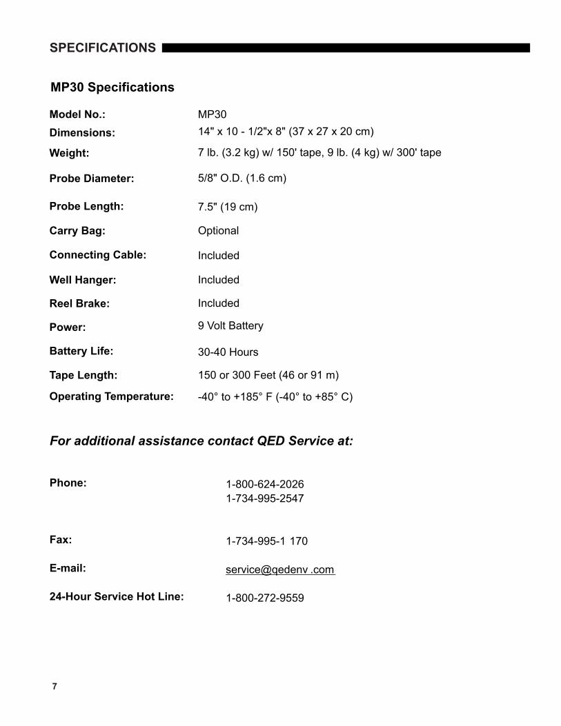
MP30 Specifications
Model No.: Dimensions:
Carry Bag:
Connecting Cable:
Reel Brake:
Power:
Battery Life:
Tape Length:
For additional assistance contact QED Service at:
Phone:
Fax:
E-mail:
24-Hour Service Hot Line:
1-800-624-20261-734-995-2547
1-734-995-1 170
1-800-272-9559
service@qedenv .com
MP3014" x 10 - 1/2"x 8" (37 x 27 x 20 cm)
7 lb. (3.2 kg) w/ 150' tape, 9 lb. (4 kg) w/ 300' tape
5/8" O.D. (1.6 cm)
7.5" (19 cm)
Optional
Included
Included
Included
9 Volt Battery
30-40 Hours
150 or 300 Feet (46 or 91 m)
-40° to +185° F (-40° to +85° C)
SPECIFICATIONS
Weight:
Probe Diameter:
Probe Length:
Well Hanger:
Operating Temperature:

8
WARRANTY
QED Monitoring System WARRANTY
QED ENVIRONMENTAL SYSTEMS, INC. ("QED") warrants to the original purchaser of its products that, subject to the limitations and conditions provided below, the products, materials and/or workmanship shall reasonably conform to descriptions of the products and shall be free of defects in materials and workmanship. Any failure of the products to conform to this warranty will be remedied by QED in the manner provided herein.
This warranty shall be limited to the duration and the conditions set forth below. Warranty duration is calc-ulated from the original date of purchase.
1. Dedicated-Use System Products-10-year warranty on dedicated bladder pumps equipped with QED inlet screens, and purge pumps used in periodic, non-continuous groundwater sampling (up to 52 samples events per year.) All other components, equipment and accessories are warranted for one year.
2. Portable-Use Systems - Controllers and Water Level Meters are warranted for one year. Hose reels, pumps and caps are warranted for ninety (90) days. Tubing and Purge Mizers are covered by a ninety- (90) day material and workmanship warranty. There will be no warranty for application on tubing and Purge Mizers when used as part of a Portable System.
3. Separately Sold Parts and Spare Parts Kit - Separately sold parts and spare parts are warranted for ninety (90) days. Repairs performed by QED are warranted for ninety (90) days from date of repair or for the full term of the original warranty, whichever is longer.
Buyers' exclusive remedy for breach of said warranty shall be as follows: if, and only if, QED is notified in writing within the applicable warranty period of the existence of any such defect in the said products, and QED upon examination of any such defects, shall find the same to be within the term of and covered by the warranty running from QED to Buyer, QED will, at its option, as soon as reasonably possible, replace or repair any such product, without charge to Buyer. If QED for any reason, cannot repair a product covered hereby within four (4) weeks after receipt of the original Purchaser's/Buyer's notification of a warranty claim, then QED's sole responsibility shall be, at its option, either to replace the defective product with a comparable new unit at no charge to the Buyer, or to refund the full purchase price. In no event shall such allegedly defective products be returned to QED without its consent, and QED's obligations of repair, replacement or refund are conditioned upon the Buyer's return of the defective product to QED.
IN NO EVENT SHALL QED ENVIRONMENTAL SYSTEMS, INC. BE LIABLE FOR CONSEQUENTIAL OR INCIDENTAL DAMAGES FOR BREACH OF SAID WARRANTY.
The foregoing warranty does not apply to major sub-assemblies and other equipment, accessories, and parts manufactured by others, and such other parts, accessories, and equipment are subject only to the warranties, if any, supplied by the respective manufacturers. QED makes no warranty concerning products or accessories not manufactured by QED. In the event of failure of any such product accessory, QED will give reasonable assistance to Buyer in obtaining from the respective manufacturer whatever adjustments is reasonable in light of the manufacturer's own warranty.
THE FOREGOING WARRANTY IS IN LIEU OF ALL OTHER WARRANTIES, EXPRESSED, IMPLIED OR STATUTORY (INCLUDING BUT NOT LIMITED TO THE WARRANTIES OF MERCHANTABILITY AND FIT-NESS FOR A PARTICULAR PURPOSE). WHICH OTHER WARRANTIES ARE EXPRESSLY EXCLUDED HEREBY, and of any other obligations or liabilities on the part of QED, and QED neither assumes nor authorizes any person to assume for it any other obligation or liability in connection with the said products, materials and/or workmanship.
It is understood and agreed that QED shall in no event be liable for incidental or consequential damages resulting from its breach of any of the terms of this agreement, not for special damages, nor for improper selection of any product described or referred to for a particular application.
This warranty will be void in the event of unauthorized disassembly of component assemblies. Defects in any equipment that result from abuse, operation in any manner outside the recommended procedures, use and applications other than for intended use, or exposure to chemical or physical environmental beyond the designated limits of materials and construction will also void this warranty. QED shall be released from all obligations under all warranties if any product covered hereby is repaired or modified by persons other than QED's service personnel unless such repair by others is made with the written consent of QED.

9
WARRANTY
QED Environmental Systems Inc.2355 Bishop Circle W.Ann Arbor, MI 48103
(800) 624-2026(734) 995-2547
This warranty will be void in the event of unauthorized disassembly of component assemblies. Defects in any equipment that result from abuse, operation in any manner outside the recommended procedures, use and applications other than for intended use, or exposure to chemical or physical environmental beyond the designated limits of materials and construction will also void this warranty. QED shall be released from all obligations under all warranties if any product covered hereby is repaired or modified by persons other than QED's service personnel unless such repair by others is made with the written consent of QED.
If any product covered hereby is actually defective within the terms of this warranty, Purchaser must contact QED for determination of warranty coverage. If the return of a component is determined to be necessary, QED will authorize the return of the component, at owner's expense. If the product proves not be defective within the terms of this warranty, then all costs and expenses in connection with the processing of the Purchaser's \claim and all costs for repair, parts and labor as authorized by owner hereunder shall be borne by the Purch-aser.
RESPONSIBILITY OF THE PURCHASER
The original Purchaser's sole responsibility in the instance of a warranty claim shall be to notify QED of the defect, malfunction, or other manner in which the terms of this warranty are believed to be violated. You may secure performance of obligations hereunder by contacting the Customer Service Department of QED and:
1. Identifying the product involved (by model or serial number or other sufficient description that will allow QED to determine which product is defective).
2. Specifying where, when, and from whom the product was purchased.
3. Describing the nature of the defect or malfunction covered by this warranty.
4. Sending the malfunction component, after authorization by QED to:


P.O. Box 3726 Ann Arbor, MI 48106-3726 USA1-800-624-2026 Fax (734) [email protected] www.qedenv.com