Embed Size (px)
Citation preview

INSTRUCTION MANUALOPHTHALMOMETER
OM-4


1INTRODUCTION
INTRODUCTION
Thank you for purchasing the TOPCON OM-4 Ophtalmometer.
This instrument is used for the measurement of the radius of curvature of the corneaand measurement of contact lenses.
This OM-4 has the following features:• Smooth operation• Robustness and durability
This Instruction Manual covers an overview of the basic operation, troubleshooting,checking, maintenance and cleaning of the OM-4 Ophthalmometer.To get the best results from this instrument, read "Displays for Safe Use" and "SafetyCautions".Keep this Instruction Manual close the instrument for future reference.
[Warning]To avoid injury to the patient’s eye and nose, pay particular attention whileoperating the instrument body.(The patient may be injured.)
This symbol is applicable for EU member countries only.To avoid potential negative consequences for the environment and possibly humanhealth, this instrument should be disposed of (i) for EU member countries - inaccordance with WEEE (Directive on Waste Electrical and Electronic Equipment),or (ii) for all other countries, in accordance with local disposal and recycling laws.

2INTRODUCTION
CAUTIONS FOR USE
Basic caution
To prevent fingers from being caught in between, beware of the moving parts while operatingthe main body.
Disposal
Dispose of the instrument according to local disposal and recycling laws.
ENVIRONMENTAL CONDITIONS FOR USE
Temperature : 10°C ~ 40°CHumidity : 30% ~ 75% (without dew condensation)Air pressure : 700hPa ~ 1060hPa
STORAGE, USAGE PERIOD AND OTHERS
1. Environmental conditions (without package)Temperature : 10°C ~ 40°CHumidity : 30% ~ 75% (without dew condensation)Air pressure : 700hPa ~ 1060hPa
2. When storing the instrument, ensure that the following conditions are met:(1) The instrument should not be splashed with water.(2) Store the instrument where environmental conditions are appropriate.(3) Do not store or transport the instrument on a slope or uneven surface or in an area
where it is subject to vibrations or instability.(4) Do not store the instrument where chemicals are stored or gas is generated.
3. Usage period8 years from delivery providing regular maintenance is performed (according to the self-cer-tification [TOPCON data])
ENVIRONMENTAL CONDITIONS FOR PACKAGING IN TRANSPORTATION
Temperature : -20°C ~ 50°CHumidity : 10% ~ 95%
CHECKPOINTS FOR MAINTENANCE
1. Regularly maintain and check the instrument and its parts.2. When using the instrument after a prolonged period of inactivity, confirm normal and safe
operation beforehand.3. Keep the objective lens free from finger prints and dust.4. When not in use, protect the instrument with the dust cover.5. If the objective lens is stained, clean it following the "Cleaning" instructions listed in this
Instruction Manual.

3DISPLAYS FOR SAFE USE
DISPLAYS FOR SAFE USE
In order to ensure the safe use of the product and to prevent harm to the operator and others, ordamage to property, a number of important warnings are placed on the product and inserted in theinstruction manual.It is recommended that all users understand the meaning of the following displays and iconsbefore reading the "Safety Cautions" text.
DISPLAYS
ICONS
DISPLAY MEANING
WARNING Ignoring or disregarding this display may lead to death or seri-ous injury.
CAUTION Ignoring or disregarding this display may lead to personal injuryor physical damage.
• Injury refers to cuts, bruises, sprains, fractures, burns, electric shocks, etc.• Physical damage refers to damage to buildings, equipment or furniture.
ICON MEANING
This indicates Prohibition.Specific content is expressed with words or an icon either insertedin the icon itself or located next to the icon.
This indicates Mandatory Action.Specific content is expressed with words or an icon either insertedin the icon itself or located next to the icon.
This icon indicates Hazard Alerting (Warning).Specific content is expressed with words or an icon either insertedin the icon itself or located next to the icon.

4SAFETY CAUTIONS
SAFETY CAUTIONS
MAINTENANCE
USER MAINTENANCE
To maintain the safety and performance of the instrument, never attempt to do mainte-nance of items other than those specified here unless done by an authorized service engi-neer. For details about maintenance, read the chapter entitled "Maintenance" in thismanual.
REPLACING THE ILLUMINATION LAMP
The illumination bulb can be replaced if necessary. For specific instructions, see page 32.
REPLACING THE FUSES
Fuses on the primary side can be replaced if necessary. For specific instructions, seepage 31.
ESCAPE CLAUSES
CAUTION
Icon Prevention item Page
This instrument has been tested (with 120V) and found to complywith IEC60601-1-2: 2001.This instrument radiates radio frequency energy within standardparameters and may affect other devices in the vicinity.If you have discovered that turning on / off the instrument affectsother devices, we recommend you change its position, keep aproper distance from other devices, or change the outlet.Please consult the dealer from whom you purchased the instru-ment for any additional questions. (for U.S.A. and Canada)
-----
• TOPCON shall not take any responsibility for damage due to fire, earthquakes, actionsby a third party or other accidents, or the negligence and misuse of the user and useunder unusual conditions.
• TOPCON shall not take any responsibility for damage derived from the inability to usethis equipment, such as a loss of business profit and suspension of business.
• TOPCON shall not take any responsibility for damage caused by operations other thanthose described in this Instruction Manual.
• Diagnoses made shall be the responsibility of the pertaining doctors and TOPCONshall not take any responsibility for the results of such diagnoses.
5WARNING INDICATIONS AND POSITIONS
WARNING INDICATIONS AND POSITIONS
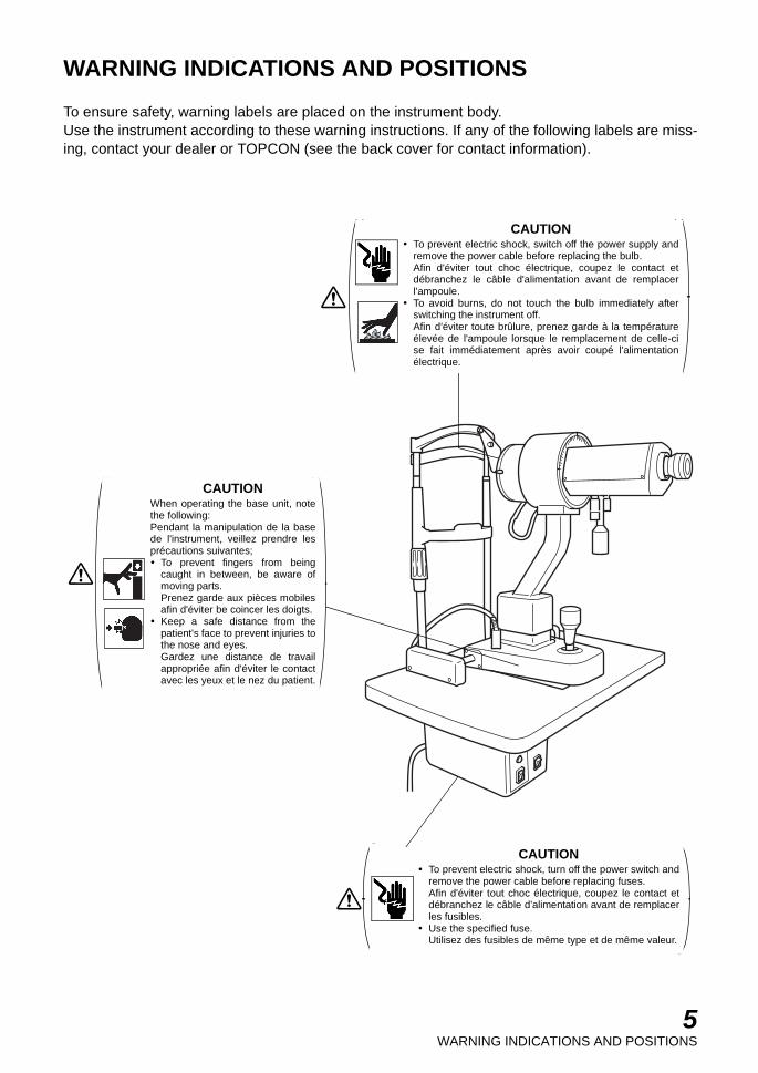
To ensure safety, warning labels are placed on the instrument body.Use the instrument according to these warning instructions. If any of the following labels are miss-ing, contact your dealer or TOPCON (see the back cover for contact information).
CAUTIONWhen operating the base unit, notethe following:Pendant la manipulation de la basede l'instrument, veillez prendre lesprécautions suivantes;
To prevent fingers from beingcaught in between, be aware ofmoving parts.Prenez garde aux pièces mobilesafin d'éviter be coincer les doigts.Keep a safe distance from thepatient's face to prevent injuries tothe nose and eyes.Gardez une distance de travailappropriée afin d'éviter le contactavec les yeux et le nez du patient.
CAUTIONTo prevent electric shock, switch off the power supply andremove the power cable before replacing the bulb.Afin d'éviter tout choc électrique, coupez le contact etdébranchez le câble d'alimentation avant de remplacerl'ampoule.To avoid burns, do not touch the bulb immediately afterswitching the instrument off.Afin d'éviter toute brûlure, prenez garde à la températureélevée de l'ampoule lorsque le remplacement de celle-cise fait immédiatement après avoir coupé l'alimentationélectrique.
CAUTIONTo prevent electric shock, turn off the power switch andremove the power cable before replacing fuses.Afin d'éviter tout choc électrique, coupez le contact etdébranchez le câble d'alimentation avant de remplacerles fusibles.Use the specified fuse.Utilisez des fusibles de même type et de même valeur.

6CONTENTS
CONTENTSINTRODUCTION ................................................................................................................1DISPLAYS FOR SAFE USE ...............................................................................................3SAFETY CAUTIONS ..........................................................................................................4MAINTENANCE..................................................................................................................4ESCAPE CLAUSES............................................................................................................4WARNING INDICATIONS AND POSITIONS......................................................................5
CONFIGURATION ..................................................................................................................7NAMES OF MAIN BODY COMPONENTS .........................................................................7CONFIGURATION OF PARTS IN CONTACT WITH PATIENT...........................................7STANDARD ACCESSORIES .............................................................................................8
COMPONENTS .....................................................................................................................10COMPONENTS ................................................................................................................10
ASSEMBLY PROCEDURE ................................................................................................ 11ASSEMBLY PROCEDURE............................................................................................... 11
OPERATION PROCEDURES ...........................................................................................14PREPARATION.................................................................................................................14PRACTICE MEASUREMENTS WITH THE TEST BALL ..................................................15MEASUREMENT OF THE RADIUS OF CURVATURE OF THE CORNEA......................17MEASUREMENT OF CONTACT LENSES.......................................................................20
BEFORE REQUESTING SERVICE.................................................................................21
FEATURES .............................................................................................................................22INTERNAL READING SCALES........................................................................................22WIDE RANGE OF MEASUREMENTS .............................................................................22HIGHLY PRECISE MEASUREMENTS.............................................................................22SPEEDY, ACCURATE FOCUSING ADJUSTMENTS.......................................................22SPEEDY ONE-POSITION MEASUREMENT ...................................................................22SUPERIOR HANDLING EASE .........................................................................................22EVALUATION OF UNUSUAL CORNEA IN IRREGULAR ASTIGMATISM .......................22AUTOMATIC INSTRUMENT TABLE ................................................................................23
SPECIFICATIONS.................................................................................................................24ELECTROMAGNETIC COMPATIBILITY ..........................................................................25SYSTEM CLASSIFICATION.............................................................................................29PURPOSE OF USE ..........................................................................................................29OPERATION PRINCIPLE .................................................................................................29SHAPE OF PLUG.............................................................................................................30SYMBOL ...........................................................................................................................30
MAINTENANCE.....................................................................................................................31DAILY CARE.....................................................................................................................31REPLACING THE FUSE ..................................................................................................31REPLACING THE CHINREST PAPER.............................................................................31REPLACING THE ILLUMINATION LAMP ........................................................................32CLEANING........................................................................................................................33ORDERING SUPPLIES ....................................................................................................34

7CONFIGURATION
CONFIGURATION
NAMES OF MAIN BODY COMPONENTS
CONFIGURATION OF PARTS IN CONTACT WITH PATIENT
Forehead rest : Polyamide resinChinrest : Polyamide resin
Eyepiece
Vertical indexProtractor scaleLeveling pin
Vertical knob
Auxiliary knobAxis rotatinghandle
Power switch
Brightness controlswitch
Power supply unitGliding plate
Joystick
Horizontal indexHorizontal knob
Connector cable
Table
Power cable
Pilot lamp
Mire plateCanthus marker Forehead rest
Occluder
Chinrest
Chinrest adjuster
Rail
Rail cover
Base lockingknob
Base
8CONFIGURATION
STANDARD ACCESSORIES
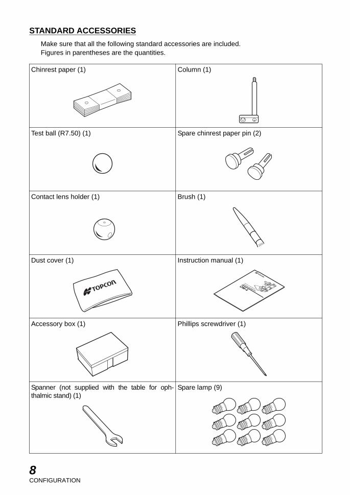
Make sure that all the following standard accessories are included.Figures in parentheses are the quantities.
Chinrest paper (1) Column (1)
Test ball (R7.50) (1) Spare chinrest paper pin (2)
Contact lens holder (1) Brush (1)
Dust cover (1) Instruction manual (1)
Accessory box (1) Phillips screwdriver (1)
Spanner (not supplied with the table for oph-thalmic stand) (1)
Spare lamp (9)
OPHTHALMOMETER
OM-4

9CONFIGURATION
Spare fuseF1, F2 : T1A 250V (100, 120V) (2)
: T0.5A 250V (220, 240V)F3 : F6A 250V
(for Europe, U.S.A. and Canada) (1)
Silicone cloth (1)
10COMPONENTS
COMPONENTS
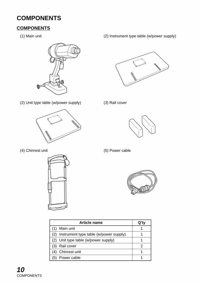
COMPONENTS
(1) Main unit (2) Instrument type table (w/power supply)
(2) Unit type table (w/power supply) (3) Rail cover
(4) Chinrest unit (5) Power cable
Article name Q'ty
(1) Main unit 1
(2) Instrument type table (w/power supply) 1
(2) Unit type table (w/power supply) 1
(3) Rail cover 2
(4) Chinrest unit 1
(5) Power cable 1

11ASSEMBLY PROCEDURE
ASSEMBLY PROCEDURE
ASSEMBLY PROCEDURE
Please check the primary voltage that the instrument is set to.(1) Installing the table
(a) Unscrew the four attachment bolts on the bottom side of the instrument's table. Thesebolts are only screwed into their screw holes temporarily and can be unscrewed very eas-ily. Use them to fix the table on top of the elevating mechanism of the adjustable instru-ment table.
(b) Install the ophthalmic stand. Simply insert the pole protruding from the bottom surface ofthe table into the socket on the lower instrument arm and tighten the fixing screw.
(2) Attachment of the chinrest unit section
Unscrew the four attachment screws which are temporarily screwed into the attachmentmount of the chinrest unit section. Then, fix the section to the mount with these four screws.
12ASSEMBLY PROCEDURE
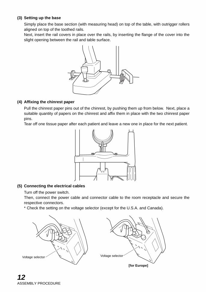
(3) Setting up the base
Simply place the base section (with measuring head) on top of the table, with outrigger rollersaligned on top of the toothed rails.Next, insert the rail covers in place over the rails, by inserting the flange of the cover into theslight opening between the rail and table surface.
(4) Affixing the chinrest paper
Pull the chinrest paper pins out of the chinrest, by pushing them up from below. Next, place asuitable quantity of papers on the chinrest and affix them in place with the two chinrest paperpins.Tear off one tissue paper after each patient and leave a new one in place for the next patient.
(5) Connecting the electrical cables
Turn off the power switch.Then, connect the power cable and connector cable to the room receptacle and secure therespective connectors.* Check the setting on the voltage selector (except for the U.S.A. and Canada).
Voltage selectorVoltage selector
[for Europe]

13ASSEMBLY PROCEDURE
(6) Checking the light
Turn on the power switch. Make sure that the pilot lamp is lit and the scale of the mire plate isilluminated.
14OPERATION PROCEDURES
OPERATION PROCEDURES
PREPARATION
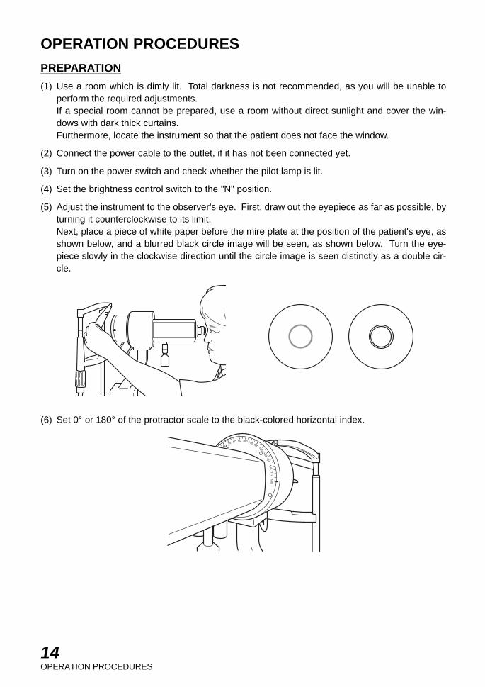
(1) Use a room which is dimly lit. Total darkness is not recommended, as you will be unable toperform the required adjustments.If a special room cannot be prepared, use a room without direct sunlight and cover the win-dows with dark thick curtains.Furthermore, locate the instrument so that the patient does not face the window.
(2) Connect the power cable to the outlet, if it has not been connected yet.
(3) Turn on the power switch and check whether the pilot lamp is lit.
(4) Set the brightness control switch to the "N" position.
(5) Adjust the instrument to the observer's eye. First, draw out the eyepiece as far as possible, byturning it counterclockwise to its limit.Next, place a piece of white paper before the mire plate at the position of the patient's eye, asshown below, and a blurred black circle image will be seen, as shown below. Turn the eye-piece slowly in the clockwise direction until the circle image is seen distinctly as a double cir-cle.
(6) Set 0° or 180° of the protractor scale to the black-colored horizontal index.
15OPERATION PROCEDURES
PRACTICE MEASUREMENTS WITH THE TEST BALL
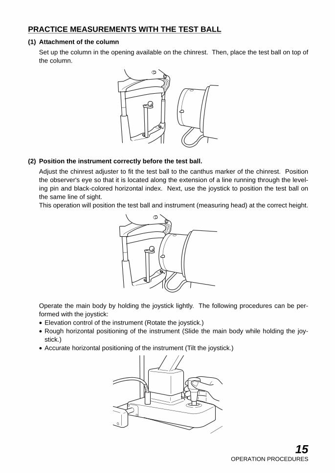
(1) Attachment of the column
Set up the column in the opening available on the chinrest. Then, place the test ball on top ofthe column.
(2) Position the instrument correctly before the test ball.
Adjust the chinrest adjuster to fit the test ball to the canthus marker of the chinrest. Positionthe observer's eye so that it is located along the extension of a line running through the level-ing pin and black-colored horizontal index. Next, use the joystick to position the test ball onthe same line of sight.This operation will position the test ball and instrument (measuring head) at the correct height.
Operate the main body by holding the joystick lightly. The following procedures can be per-formed with the joystick:• Elevation control of the instrument (Rotate the joystick.)• Rough horizontal positioning of the instrument (Slide the main body while holding the joy-
stick.)• Accurate horizontal positioning of the instrument (Tilt the joystick.)

16OPERATION PROCEDURES
Next, use the joystick to position the measuring head in front of the test ball while looking intothe eyepiece, so that the mire images show up in the field of view.The mire image in the center of the field of view will be seen as a double image as shownbelow, when the instrument is not positioned at the correct distance to the test ball.
The instrument will be set to the correct distance when the double images in the center of thefield of view are unified into a single image by adjusting the joystick. The unified image shouldbe located approximately in the center of the field of view at this time. But, if it is not, use thejoystick to center it properly so that it is concentric with the double images in the center of thefield of view.
(3) Measurement
Three mire images, as shown above, should be seen in the eyepiece at this time, and the hori-zontal knob and vertical knob should be turned to unify the "|" mark of the left mire image withthe "¦" mark of the center mire image, and the "---|---" mark of the top mire image with the "--|--"mark of the center image, which will be the result of the measurement, to be read as follows:
V
H
38.5 3938
38.5 3938
8.5 8.6 8.7
8.5 8.6 8.7
V
H
38.5 3938
38.5 3938
8.5 8.6 8.7
8.5 8.6 8.7
V
H
45.5 44.545
45.5 44.545
7.6 7.5 7.4
7.6 7.5 7.4
Reading of the vertical scale: 7.50mm (45.0 dptr)
Reading of the horizontal scale: 7.50mm (45.0 dptr)

17OPERATION PROCEDURES
When the readings of the horizontal and vertical scales are identical, it will not be necessary todetermine the axis. The test ball is supplied for the purpose of practicing measurements aswell as for checking the accuracy of the instrument which should be undertaken from time totime.The horizontal knob, vertical knob and axis rotating handle can be manipulated with one handafter a little practice. Operations will be even simpler. In this case, if the auxiliary knob isattached to the horizontal knob, in the case of a right-handed person, and to the vertical knob,in the case of a left-handed person, it will make operations much easier.
MEASUREMENT OF THE RADIUS OF CURVATURE OF THE CORNEA
(1) Positioning the patient
Place a suitable quantity of papers on the chinrest and fix them in place, with the two chinrestpaper pins, as in step (4) of "ASSEMBLY PROCEDURE" (see pg. 12).Have the patient sit in a relaxed position in front of the instrument. Next, move the adjustableinstrument table up or down (ex. AIT-10B, an optional accessory) to adjust the patient's eyeheight point outline according to the canthus marker of the chinrest. Adjust the chinrestadjuster accordingly. Instruct the patient to place his/her chin on the chinrest and his/her fore-head against the forehead rest.
(2) Positioning the instrument in front of the patient
The same operations undertaken for positioning the instrument before the test ball should beundertaken now, not for the test ball but for the patient's eye.In other words, position the observer's eye so that the leveling pin, black-colored horizontalindex and patient's eye are all on the same line of sight, using the joystick if necessary, for thispurpose.

18OPERATION PROCEDURES
Next, cover the other eye with the occluder so the patient can not see with it.Once the height of the instrument and patient's eye have been properly adjusted in the abovemanner, use the joystick to produce the mire images.
In case the image is dark and hard to see, turn the brightness control switch to the "H" posi-tion. However, do not make the image too bright, as it will not only tire the patient but also willshorten the lamp life.For the purpose of making measurements easier and for obtaining accurate results, thepatient should be warned against moving his/her face. The patient should look at the pupilimage reflected in the reflection mirror directly in front, without shifting the eye. The instrumentwill be set to the correct distance when the double images, in the center of field of view, areunified into a single image by turning the joystick.
(3) Measurements
(a) When there is corneal astigmatismTurn the axis rotating handle, when corneal astigmatism exits. The "---|---" mark of the topmire image and the "--|--" mark of the center mire image will be seen in the displaced posi-tions.
V
H
38.5 3938
38.5 3938
8.5 8.6 8.7
8.5 8.6 8.7

19OPERATION PROCEDURES
Turn the axis rotating handle and rotate the measuring head until the displacement in themarks is eliminated. (This will result in fitting the measuring head to the axis of the cornealastigmatism.)
Unify the "|" mark of the left mire image with the "¦" mark of the center mire image and the"---|---" mark of the top mire image with the "--|--" mark of the center mire image, at this angle,with the horizontal and vertical knobs, which shows how simple and fast one-position mea-surement is.
Read the measurement results. In the case of the above figure, the vertical scale indi-cates the radius of curvature of the cornea, 7.50mm (refractive power of the cornea is 45.0dptr) and the axis is 110° (read off the vertical index).The horizontal scale shows that the radius of curvature of the cornea is 7.70mm (cornealrefractive power is 43.8 dptr) and the axis is 200° (the axis of the horizontal scale is readoff the horizontal index).
(b) When corneal astigmatism does not exist:If corneal astigmatism does not exist, there will be no displacement in the marks, evenwhen the measuring head is rotated. Therefore, measurement will be the same as whenmeasuring the test ball. (See Step (3) of "PRACTICE MEASUREMENTS WITH THE TESTBALL" on pg. 16.)The measurement results are the value along the circumference of the corneal surface of2.3mm to 4.9mm diameters (at 5.5mm to 12mm radius of curvature of the cornea).
V
H
38.5 3938
38.5 3938
8.5 8.6 8.7
8.5 8.6 8.7
V
H
45.544.5
45
44.543.5
4443
7.67.5
7.4
7.67.5
7.4
010
2030
4050
60
7080
90 100 110 120 130140
150
160170
180
20OPERATION PROCEDURES
MEASUREMENT OF CONTACT LENSES
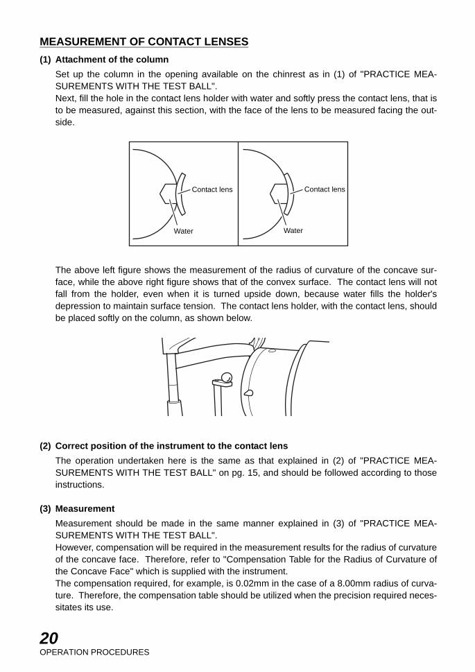
(1) Attachment of the column
Set up the column in the opening available on the chinrest as in (1) of "PRACTICE MEA-SUREMENTS WITH THE TEST BALL".Next, fill the hole in the contact lens holder with water and softly press the contact lens, that isto be measured, against this section, with the face of the lens to be measured facing the out-side.
The above left figure shows the measurement of the radius of curvature of the concave sur-face, while the above right figure shows that of the convex surface. The contact lens will notfall from the holder, even when it is turned upside down, because water fills the holder'sdepression to maintain surface tension. The contact lens holder, with the contact lens, shouldbe placed softly on the column, as shown below.
(2) Correct position of the instrument to the contact lens
The operation undertaken here is the same as that explained in (2) of "PRACTICE MEA-SUREMENTS WITH THE TEST BALL" on pg. 15, and should be followed according to thoseinstructions.
(3) Measurement
Measurement should be made in the same manner explained in (3) of "PRACTICE MEA-SUREMENTS WITH THE TEST BALL".However, compensation will be required in the measurement results for the radius of curvatureof the concave face. Therefore, refer to "Compensation Table for the Radius of Curvature ofthe Concave Face" which is supplied with the instrument.The compensation required, for example, is 0.02mm in the case of a 8.00mm radius of curva-ture. Therefore, the compensation table should be utilized when the precision required neces-sitates its use.
Contact lens
Water
Contact lens
Water

21BEFORE REQUESTING SERVICE
BEFORE REQUESTING SERVICEIf something is wrong with the instrument, please check the following points before contactingyour authorized distributor for repair.
Illumination lamp does not light up.
(1) Check whether the power cable and connector cable are properly connected.
(2) Check fuses.
If some of the wires become dark because of burned out bulb, please see "REPLACING THEILLUMINATION LAMP" on pg. 32 in the "MAINTENANCE" section of the manual.

22FEATURES
FEATURES
INTERNAL READING SCALES
The millimeter scales for the radius of curvature (bottom figures) and the diopter scales for thecorneal refractive power (top figures) of both horizontal (H) and vertical (V) axes, are seen inthe field of view, together with the mire images, during the measurement.
WIDE RANGE OF MEASUREMENTS
The range of measurements is extremely wide, with the millimeter scale covering 5.5 to12.0mm and the diopter scale covering 60 to 28 diopters.
HIGHLY PRECISE MEASUREMENTS
Mire images are very sharp and easy to coincide, producing the measurement results with theminimum of individual variations.
SPEEDY, ACCURATE FOCUSING ADJUSTMENTS
Focusing adjustments are quick but very accurate, because they only require coincidence ofdouble images without individual variations.
SPEEDY ONE-POSITION MEASUREMENT
While measuring one of the principal meridians with the TOPCON Opthalmometer, the otherprincipal meridian is automatically measured at the same time. Therefore, it is not necessaryto measure both principal meridians separately, in the case of corneal astigmatism. Thismakes measurement quicker than the Two-Position method and also more accurate.
SUPERIOR HANDLING EASE
The horizontal and vertical knobs, as well as the axis rotating handle, are located for simpleoperational ease. They allow for one-hand operation of the auxiliary knob which increaseshandling ease for both right-handed and left-handed persons. In addition, there is animproved joystick which can adjust not only elevation control of the instrument but also hori-zontal positioning of the instrument.
EVALUATION OF UNUSUAL CORNEA IN IRREGULAR ASTIGMATISM
Evaluation is possible by simply checking the shape of mire image.

23FEATURES
AUTOMATIC INSTRUMENT TABLE
Specifications
AIT-15• Dimensions ......................510(W)×450(D)mm• Table height......................600~820mm• Table size .........................490×500mm• Weight ..............................approx. 23kg• Power consumption .........270VA (100-120V, 220-240V)
AIT-16• Dimensions ......................525(W)×490(D)mm• Table height......................660~880mm• Table size .........................490×500mm• Weight ..............................approx. 23kg• Source voltage .................230V AC, 50/60Hz (for Europe)
120V AC, 50/60Hz (for U.S.A. and Canada)220/240V AC, 50/60Hz (for the other area)
• Power consumption .........220VA (100-120V, 220-240V)• Short-time opration ..........2min

24SPECIFICATIONS
SPECIFICATIONS
Subject to change in design and/or specifications without advance notice.
MEASURING HEAD
Type Sutcliffe type
Magnification 20×
Eyepiece adjustment range 0 to ±5 dptr
Measuring range
Corneal radius of curvature 5.5 to 12mm
Minimum reading 0.01mm
Corneal refractive power 60 to 28 dptr
Minimum reading 0.125 dptr
Axis corneal astigmatism 0 to 180°
Scale reading systemInternal reading radius of curvature and refractive powerscales; external reading protractor scale.
Lamp 6V-3W (8 each)
BASE
Longitudinal base travel 90mm
Lateral base travel 100mm
Fine cross-slide base adjustments 15mm
Vertical travel of measuring head 30mm
Vertical travel of chinrest 80mm
POWER UNIT
(Except for U.S.A. and Canada)Primary AC 100/120/220/240V;
Adjustable with voltage selector
(For U.S.A. and Canada)Primary AC 120V
(All areas)FrequencySecondaryPower consumption
50/60HzAC 6V and 7.5V; adjustable with switch30VA
DIMENSIONS AND WEIGHT
Unit model 440mm × 350mm 16kg
Table model 550mm × 370mm 16kg

25SPECIFICATIONS
ELECTROMAGNETIC COMPATIBILITY
This product conforms to the EMC Standard (IEC 60601-1-2:2001).
a) MEDICAL ELECTRICAL EQUIPMENT needs special precautions regarding EMC andneeds to be installed and put into service according to the EMC information provided in theACCOMPANYING DOCUMENTS.
b) Portable and mobile RF communications equipment can affect MEDICAL ELECTRICALEQUIPMENT.
c) The use of ACCESSORIES, transducers and cables other than those specified, with theexception of transducers and cables sold by the manufacturer of the EQUIPMENT or SYS-TEM as replacement parts for internal components, may result in increased EMISSIONS ordecreased IMMUNITY of the EQUIPMENT or SYSTEM.
d) The EQUIPMENT or SYSTEM should not be used adjacent to or stacked with other equip-ment. IF adjacent or stacked use is necessary, the EQUIPMENT or SYSTEM should beobserved to verify normal operation in the configuration in which it will be used.
Guidance and manufacturer's declaration - electromagnetic emissions
The OM-4 is intended for use in the electromagnetic environment specified below.The customer or the user of the OM-4 should assure that it is used in such an environment.
Emissions test Compliance Electromagnetic environment - guidance
RF emissionsCISPR 11
Group 1
The OM-4 uses RF energy only for its internal func-tion. Therefore, its RF emissions are very low andare not likely to cause any interference in nearbyelectronic equipment.
RF emissionsCISPR 11
Class A
The OM-4 is suitable for use in all establishmentsother than domestic and those directly connected tothe public low-voltage power supply network thatsupplies buildings used for domestic purposes.
Harmonic emissionsIEC61000-3-2
Class A
Voltage fluctuations/flicker emissionsIEC61000-3-3
Complies
26SPECIFICATIONS
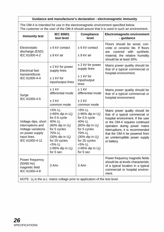
Guidance and manufacturer's declaration - electromagnetic immunity
The OM-4 is intended for use in the electromagnetic environment specified below.The customer or the user of the OM-4 should assure that it is used in such an environment.
Immunity testIEC 60601test level
Compliance level
Electromagnetic environment - guidance
Electrostaticdischarge (ESD)IEC 61000-4-2
± 6 kV contact
± 8 kV air
± 6 kV contact
± 8 kV air
Floors should be wood, con-crete or ceramic tile. If floorsare covered with syntheticmaterial, the relative humidityshould be at least 30%.
Electrical fasttransient/burstIEC 61000-4-4
± 2 kV for powersupply lines
± 1 kV forinput/output lines
± 2 kV for powersupply lines
± 1 kV forinput/outputlines
Mains power quality should bethat of a typical commercial orhospital environment.
SurgeIEC 61000-4-5
± 1 kVdifferential mode
± 2 kVcommon mode
± 1 kVdifferential mode
± 2 kVcommon mode
Mains power quality should bethat of a typical commercial orhospital environment.
Voltage dips, shortinterruptions andVoltage variationson power supplyinput linesIEC 61000-4-11
<5% Ut(>95% dip in Ut)for 0.5 cycle40% Ut(60% dip in Ut)for 5 cycles70% Ut(30% dip in Ut)for 25 cycles<5% Ut(>95% dip in Ut)for 5 sec
<5% Ut(>95% dip in Ut)for 0.5 cycle40% Ut(60% dip in Ut)for 5 cycles70% Ut(30% dip in Ut)for 25 cycles<5% Ut(>95% dip in Ut)for 5 sec
Mains power quality should bethat of a typical commercial orhospital environment. If the useror the OM-4 requires continuedoperation during power mainsinterruptions, it is recommendedthat the OM-4 be powered froman uninterruptible power supplyor battery.
Power frequency(50/60 Hz)magnetic fieldIEC 61000-4-8
3 A/m 3 A/m
Power frequency magnetic fieldsshould be at levels characteristicof a typical location in a typicalcommercial or hospital environ-ment.
NOTE Ut is the a.c. mains voltage prior to application of the test level.

27SPECIFICATIONS
Guidance and manufacturer's declaration - electromagnetic immunity
The OM-4 is intended for use in the electromagnetic environment specified below.The customer or the user of the OM-4 should assure that it is used in such an environment.
Immunity test IEC 60601test level
Compliance level
Electromagnetic environment - guidance
Conducted RFIEC 61000-4-6
Radiated RFIEC 61000-4-3
3 Vrms150kHz to 80MHz
3 V/m80MHz to 2.5GHz
3 V
3 V/m
Portable and mobile RF communica-tions equipment should be used nocloser to any part of the OM-4, includ-ing cables, than the recommendedseparation distance calculated from theequation applicable to the frequency ofthe transmitter.
Recommended separation distance
d = 1.2
d = 1.2 80MHz to 800MHzd = 2.3 800MHz to 2.5GHz
where P is the maximum output powerrating of the transmitter in watts (W)according to the transmitter manufac-turer and d is the recommended sepa-ration distance in meters (m).
Field strengths from fixed RF transmit-ters, as determined by an electromag-netic site survey, a should be less thanthe compliance level in each frequencyrange. b
Interference may occur in the vicinity ofequipment marked with the followingsymbol:
NOTE 1NOTE 2
At 80 MHz and 800 MHz, the higher frequency range applies.These guidelines may not apply in all situations. Electromagnetic propagation isaffected by absorption and reflection from structures, objects and people.
a
b
Field strengths from fixed transmitters, such as base stations for radio (cellular/cordless)telephones and land mobile radios, amateur radio, AM and FM radio broadcast and TVbroadcast cannot be predicted theoretically with accuracy. To assess the electromagneticenvironment due to fixed RF transmitters, an electromagnetic site survey should be con-sidered. If the measured field strength in the location in which the OM-4 is used exceedsthe applicable RF compliance level above, the OM-4 should be observed to verify normaloperation. If abnormal performance is observed, additional measures may be necessary,such as reorienting or relocating the OM-4.
Over the frequency range 150 kHz to 80 MHz, field strengths should be less than 3 V/m.
P
PP

28SPECIFICATIONS
Recommended separation distance betweenportable and mobile RF communications equipment and the OM-4
The OM-4 is intended for use in an electromagnetic environment in which radiated RF distur-bances are controlled. The customer or the user of the OM-4 can help prevent electromag-netic interference by maintaining a minimum distance between portable and mobile RFcommunications equipment (transmitters) and the OM-4 as recommended below, accordingto the maximum output power of the communications equipment.
Rated maximum output power of transmitter
W
Separation distance according to frequency of transmitterm
150kHz to 80MHzd = 1.2
80MHz to 800MHzd = 1.2
800MHz to 2.5GHzd = 2.3
0.01 0.12 0.12 0.23
0.1 0.38 0.38 0.73
1 1.2 1.2 2.3
10 3.8 3.8 7.3
100 12 12 23
For transmitters rated at a maximum output power not listed above, the recommended sepa-ration distance d in meters (m) can be estimated using the equation applicable to the fre-quency of the transmitter, where P is the maximum output power rating of the transmitter inwatts (W) according to the transmitter manufacturer.
NOTE 1
NOTE 2
At 80 MHz and 800 MHz, the separation distance for the higher frequency rangeapplies.These guidelines may not apply in all situations. Electromagnetic propagation isaffected by absorption and reflection from structures, objects and people.
P P P

29SPECIFICATIONS
SYSTEM CLASSIFICATION
• Type of protection against electric shocks: Type B applied partType B applied part is the applied part complying with the specified requirements of theStandard IEC 60601-1 to provide protection against electric shock, particularly regardingallowable LEAKAGE CURRENT.
• Type of protection against electric shocks: Class I equipmentClass I equipment does not depend on basic insulation only for protection against electricshocks. It can also be earthed; therefore, the metal parts with which one comes into contactdo not become conductive if the basic insulation fails.
• The mode of operation: continuous operation equipment• Degree of protection against ingress of water: IP×0
OM-4 is the ordinary instrument (enclosed instrument without protection against ingress ofwater)
• Methods of sterilization or disinfection recommended by the manufacture: OM-4 does nothave any part to be sterilized or disinfected.
• Not AP or APG equipment
PURPOSE OF USE
This instrument is used to measure the radius of curvature of the cornea.It displays the corneal refractive power according to the above measurement result. It is alsoused to measure the base curve of contact lens.
OPERATION PRINCIPLE
Projects the measurement index to the cornea and measures the radius of curvature of the cor-nea according to the corneal reflected image.
30SPECIFICATIONS
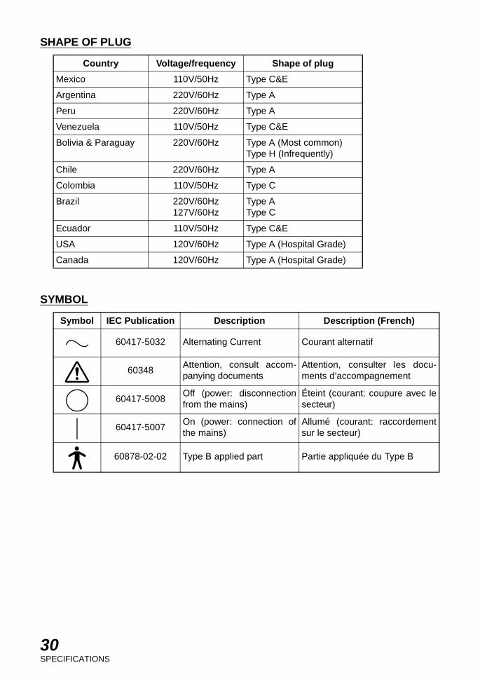
SHAPE OF PLUG
SYMBOL
Country Voltage/frequency Shape of plug
Mexico 110V/50Hz Type C&E
Argentina 220V/60Hz Type A
Peru 220V/60Hz Type A
Venezuela 110V/50Hz Type C&E
Bolivia & Paraguay 220V/60Hz Type A (Most common)Type H (Infrequently)
Chile 220V/60Hz Type A
Colombia 110V/50Hz Type C
Brazil 220V/60Hz127V/60Hz
Type AType C
Ecuador 110V/50Hz Type C&E
USA 120V/60Hz Type A (Hospital Grade)
Canada 120V/60Hz Type A (Hospital Grade)
Symbol IEC Publication Description Description (French)
60417-5032 Alternating Current Courant alternatif
60348Attention, consult accom-panying documents
Attention, consulter les docu-ments d’accompagnement
60417-5008Off (power: disconnectionfrom the mains)
Éteint (courant: coupure avec lesecteur)
60417-5007On (power: connection ofthe mains)
Allumé (courant: raccordementsur le secteur)
60878-02-02 Type B applied part Partie appliquée du Type B

31MAINTENANCE
MAINTENANCE
DAILY CARE
* Remove dust from the instrument except the lenses and prisms, using a dry soft cloth at reg-ular intervals.
* This instrument may be adversely affected by dust. Apply the dust cover when not in use.
REPLACING THE FUSE
* First, turn the power switch OFF, and remove the power cable from the outlet.* With a Phillips screwdriver, turn the center of the fuse holder at the back of the power unit.
The fuse will come out.* Replace it with a new fuse and then tighten the center of the fuse holder.* Always use the same type of fuse as indicated in the holder:
F1, F2: T1A 250V (100,120V): T0.5A 250V (220,240V)
F3 : F6A 250V (for Europe, U.S.A. and Canada)
REPLACING THE CHINREST PAPER
If the chinrest paper supply is depleted, remove the pins from the chinrest, place the newpackage of paper on the chinrest and replace the two locating pins.
Pin

32MAINTENANCE
REPLACING THE ILLUMINATION LAMP
This mire plate and lamp will be hot if the lamp burns out while the instrument is in use. Let them cool down and then replace the lamp in the following manner:
(1) After switching off the instrument, disconnect the power cable.
(2) Unscrew the leveling pin until loose. Do not remove completely.
(3) Pull out the mire plate to expose the lamp. Unscrew and remove burned out bulb.
(4) Insert the new bulb and screw it down until securely attached.
(5) Replace the mire plate. The mire plate is notched. Fit the notched section with an alignmentpin inside the instrument. Push it in fully and then screw in the leveling pin which will securethe mire plate.
(6) Connect the power cable. Turn on the power switch and check if the illumination lamps lightup.

33MAINTENANCE
CLEANING
(1) Cleaning the lens and mirror
If any dust settles on the lens or mirror, remove it as follows:Use the cleaning brush, which is included in the standard accessories, to remove the dust. Incase any dust still remains, wipe it off using a soft cotton cloth moistened with a little alcohol.Never use your finger or any hard object to clean the lens or mirror.
(2) Cleaning the gliding plate, base rail and shaft
If the gliding plate or cross-slide rail and shaft are dirty, an unsmooth vertical or horizontalmovement of the cross-slide results. Clean them with a dry cloth.
(3) Cleaning the plastic parts
To clean the plastic parts, such as chinrest and forehead rest, use only a cloth moistened witha solution of neutral detergent and water to wipe off the accumulated dust. Avoid using othertypes of cleansers.
(4) Cleaning applied parts
Wipe the forehead rest and chinrest with a cloth moistened with a tepid solution of neutraldetergent for kitchenware
Shaft
Rail
Gliding plate

34MAINTENANCE
ORDERING SUPPLIES
To order the following replacement parts, be sure to specify the product name, part numberand quantity required.
Product name Part number Appearance
Lamp 40120 1008
Chinrest paper 40310 4082
FuseF1, F2: T1A 250V (100, 120V)
: T0.5A 250V (220, 240V)F3 : F6A 250V
(for Europe, U.S.A. and Canada)
44635 600344635 600444630 6776

When contacting us, please have the following information at hand reyour unit:• Machine type: OM-4• Manufacturing No. (Displayed on the rating plate on the left of the
base.)• Period of Usage (i. e. the purchase date).• Description of Problem (as detailed as possible).
OPHTHALMOMETER OM-4
INSTRUCTION MANUAL
The 2005 version (2005.11-100TH )Date of issue: 1st, November 2005
Published by TOPCON CORPORATION
75-1 Hasunuma-cho, Itabashi-ku, Tokyo, 174-8580 Japan.
©2005 TOPCON CORPORATION ALL RIGHTS RESERVED
3

OPHTHALMOMETER
OM-4
75-1 Hasunuma-cho,Itabashi-ku,Tokyo,174-8580 Japan.
Phone:3-3558-2520 Fax:3-3960-4214 www.topcon.co.jp
37 West Century Road,Paramus,New Jersey 07652,U.S.A. Phone:201-261-9450 Fax:201-387-2710 www.topcon.comTOPCON MEDICAL SYSTEMS, INC
(European Representative)Essebaan 11, 2908 LJ Capelle a/d IJssel,THE NETHERLANDS Phone:010-4585077 Fax:010-4585045 www.topconeurope.com
TOPCON EUROPE B.V.
Giesserallee 31-33 D-47877 Willich GERMANY Phone:02154-8850 Fax:02154-885111 www.topcon.de [email protected] TOPCON DEUTSCHLAND G.m.b.H.
110 Provencher Avenue, Boisbriand, QC J7G 1N1 CANADA Phone:450-430-7771 Fax:450-430-6457 www.topcon.ca TOPCON CANADA INC.
HEAD OFFICE:Frederic Mompou 5, ED. Euro 3, 08960,Sant Just Desvern Barcelona,SPAIN Phone:93-4734057 Fax:93-4733932 www.topconesp.comMADRID OFFICE:Avenida Burgos, 16E,1˚ 28036,Madrid,SPAIN Phone:91-302-4129 Fax:91-383-3890
TOPCON ESPAÑA S.A.
Neongatan 2 S-43151 Mölndal, SWEDEN Phone:031-7109200 Fax:031-7109249 [email protected] SCANDINAVIA A.B.
Topcon House,Kennet Side,Bone Lane,Newbury,Berkshire RG14 5PX United Kingdom Phone:01635-551120 Fax:01635-551170TOPCON (GREAT BRITAIN) LTD.
Blk 192 Pandan Loop, #07-01 Pantech Industrial Complex, SINGAPORE 128381 Phone:62780222 Fax:62733540 www.topcon.com.sgTOPCON SOUTH ASIA PTE.LTD.
Excella Business Park Block C,1st Floor,Jalan Ampang Putra,Taman Ampang Hillir, 55100 Kuala Lumpur,MALAYSIA Phone:03-42701192 Fax:03-42704508TOPCON INSTRUMENTS (MALAYSIA) SDN.BHD.
77/162 Sinn Sathorn Tower, 37th Fl.,Krungdhonburi Rd.,Klongtonsai, Klongsarn, Bangkok 10600,THAILAND Phone:440-1152~7 Fax:440-1158TOPCON INSTRUMENTS (THAILAND) CO.,LTD.
Unit 18,4 Avenue of Americas Newington NSW 2127 AUSTRALIA Phone:02-8748-8777 Fax:02-9647-2926 www.topcon.com.au TOPCON AUSTRALIA PTY.LTD.
2F Yooseoung Bldg., 1595-3, Seocho-Dong, Seocho-Gu, Seoul, 137-876 KOREA Phone:02-2055-0321 Fax:02-2055-0319 www.topcon.co.krTOPCON KOREA CORPORATION
2/F.,Meeco Industrial Bldg.,No.53-55 Au Pui Wan Street,Fo Tan Road,Shatin,N.T.,Hong Kong Phone:2690-1328 Fax:2690-2221 E-mail:[email protected] OPTICAL (H.K.) LTD.
1070 Poly Plaza Building,14 Dongzhimen Nandajie Dongcheng District,Beijing,100027,CHINA Phone:10-6501-4191 Fax:10-6501-4190TOPCON CORPORATION BEIJING OFFICE
P.O.Box 70-1002 Antelias,BEIRUT-LEBANON Phone:961-4-523525/523526 Fax:961-4-521119TOPCON CORPORATION BEIRUT OFFICE
C/O Atlas Medical FZCO., P.O.Box 54304 C-25, Dubai Airport Free Zone, UAE Phone:971-4-2995900 Fax:971-4-2995901TOPCON CORPORATION DUBAI OFFICE
89, rue de Paris 92585 Clichy, Cedex,FRANCE Phone:01-4106-9494 Fax:01-4739-0251TOPCON S.A.R.L.
(European Sole Sales Company) Essebaan 11, 2908 LJ Capelle a/d IJssel,THE NETHERLANDS Phone:010-4585077 Fax:010-2844940 www.topconeurope.com
TOPCON EUROPE MEDICAL B.V.
ITALY OFFICE:Via Dell' Industria n.60, 20037 Paderno Dugnano, (Milano), ITALY Phone:02-61-25-583 E-mail:[email protected] www.topcon.it
40130 95993Printed in Japan 0511-100TH 3


![Industrial Sewing Machine TECHNICAL MANUAL · 2020. 11. 26. · For safe use [1] For safe use For safe use Always observe the following matters to safely use the Mitsubishi industrial](https://img.dokumen.tips/doc/110x75/60ce87b06b301a5dad5fa055/industrial-sewing-machine-technical-manual-2020-11-26-for-safe-use-1-for.jpg)