Embed Size (px)
Citation preview

Instruction Manual
ControlPads
Novara3000 Series ControlPads
CP-3006, CP-3008, CP-3017-NA, CP-3017-TR-US
Last Revised: 7/22/2014
AMX DOMESTIC CHANNEL PARTNER and END CUSTOMER LIMITED WARRANTY, DISCLAIMER AND LICENSE
(Excerpt from CHANNEL PARTNER TERMS AND CONDITIONS Versions 11.17.2011 with updates for previous version 8.25.2010 [sections 6.1 (a), (b) and (f)])
Definitions
“End Customer” means an authorized end customer with direct in warranty privileges from AMX. Within this limited warranty, disclaimer and license document, “End Customer” shall have the same meaning as “Channel Partner” with the noted exceptions of Sections 6.5 through 6.9 which are not applicable or available to End Customer’s directly from AMX. Offerings described in Sections 6.5 through 6.9 are available to End Customer only through their selected authorized AMX Channel Partner.
6. LIMITED WARRANTY; RETURN, REPAIR AND REPLACEMENT
6.1 AMX warrants the Products to be free of material defects in materials and workmanship under normal use for three (3) years from the Shipping Date (or such other period as may be specified below), subject to the following limitations and exceptions (“Limited Warranty”). For any Product, “Warranty Period” means the period during which the Limited Warranty is in effect, as set forth herein.
(a) LCD and LED panels are warranted for three (3) years from the Shipping Date, except for the display and touch overlay components, which are warranted for a period of one (1) year from the Shipping Date.
(b) Disk drive mechanisms, pan/tilt heads and external power supplies are warranted for a period of one (1) year from the Shipping Date.
(c) AMX lighting Products are warranted to switch on and off any load that is properly connected to our lighting Products, as long as the AMX lighting Products are under warranty. AMX also warrants the control of dimmable loads that are properly connected to our lighting Products. The dimming performance or quality thereof is not warranted, due to the random combinations of dimmers, lamps and ballasts or transformers.
(d) AMX software and firmware included in the Products is warranted for a period of ninety (90) days from the Shipping Date.
(e) Batteries and incandescent lamps are not covered under the Limited Warranty.
(f) The Warranty Period for AMX AutoPatch EPICA, Enova DGX, Modula, Modula Series 4, Modula Cat Pro Series and 8Y-3000 Product models will continue for the original installation until five (5) years after the issuance of a PDN with respect to termination of the applicable Product model. However, if the Product is moved from its original installation to a different installation, the Warranty Period will automatically become three (3) years from the Shipping Date and, if more than three (3) years have elapsed since the Shipping Date, the Warranty Period will automatically expire.
DLI-6293353v1
Note: Refer to www.amx.com to view/download the latest complete AMX Warranty and Return Policies.
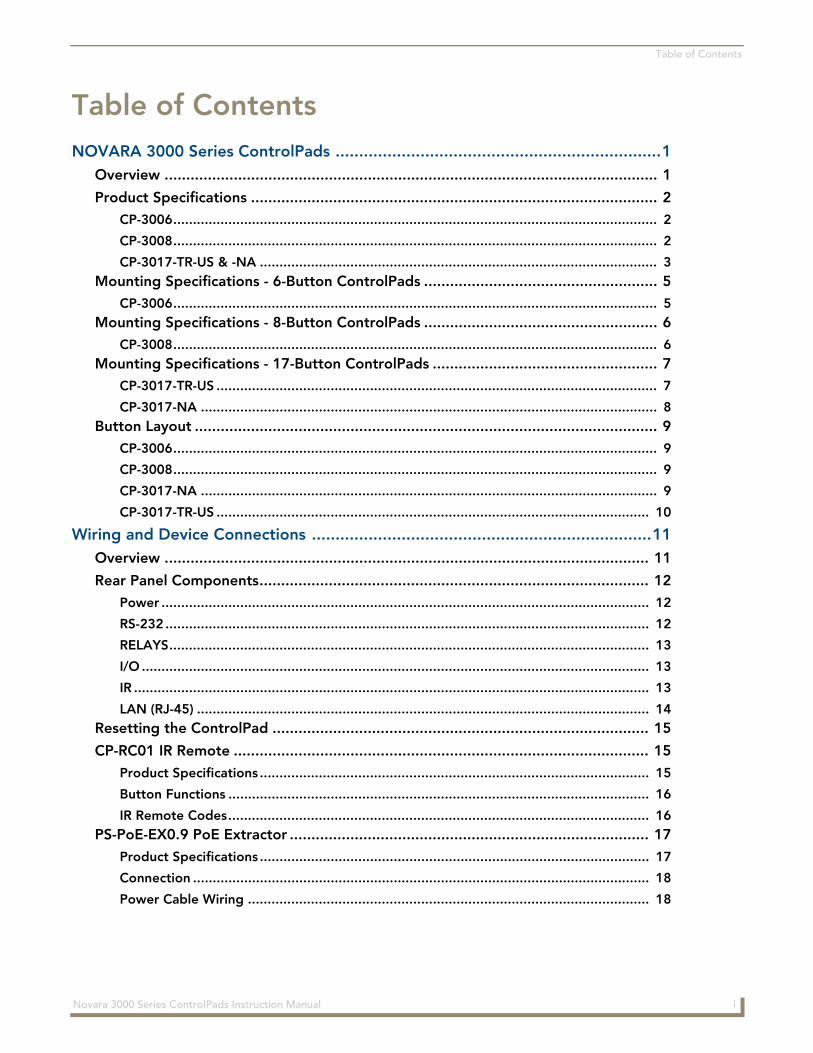
Table of Contents
Table of ContentsNOVARA 3000 Series ControlPads .....................................................................1
Overview .................................................................................................................. 1
Product Specifications .............................................................................................. 2
CP-3006........................................................................................................................... 2
CP-3008........................................................................................................................... 2
CP-3017-TR-US & -NA ..................................................................................................... 3
Mounting Specifications - 6-Button ControlPads ...................................................... 5
CP-3006........................................................................................................................... 5Mounting Specifications - 8-Button ControlPads ...................................................... 6
CP-3008........................................................................................................................... 6Mounting Specifications - 17-Button ControlPads .................................................... 7
CP-3017-TR-US ................................................................................................................ 7
CP-3017-NA .................................................................................................................... 8
Button Layout ........................................................................................................... 9
CP-3006........................................................................................................................... 9
CP-3008........................................................................................................................... 9
CP-3017-NA .................................................................................................................... 9
CP-3017-TR-US .............................................................................................................. 10
Wiring and Device Connections ........................................................................11Overview ................................................................................................................ 11
Rear Panel Components.......................................................................................... 12
Power ............................................................................................................................ 12
RS-232 ........................................................................................................................... 12
RELAYS.......................................................................................................................... 13
I/O ................................................................................................................................. 13
IR ................................................................................................................................... 13
LAN (RJ-45) ................................................................................................................... 14Resetting the ControlPad ....................................................................................... 15
CP-RC01 IR Remote ................................................................................................ 15
Product Specifications ................................................................................................... 15
Button Functions ........................................................................................................... 16
IR Remote Codes........................................................................................................... 16PS-PoE-EX0.9 PoE Extractor ................................................................................... 17
Product Specifications ................................................................................................... 17
Connection .................................................................................................................... 18
Power Cable Wiring ...................................................................................................... 18
iNovara 3000 Series ControlPads Instruction Manual
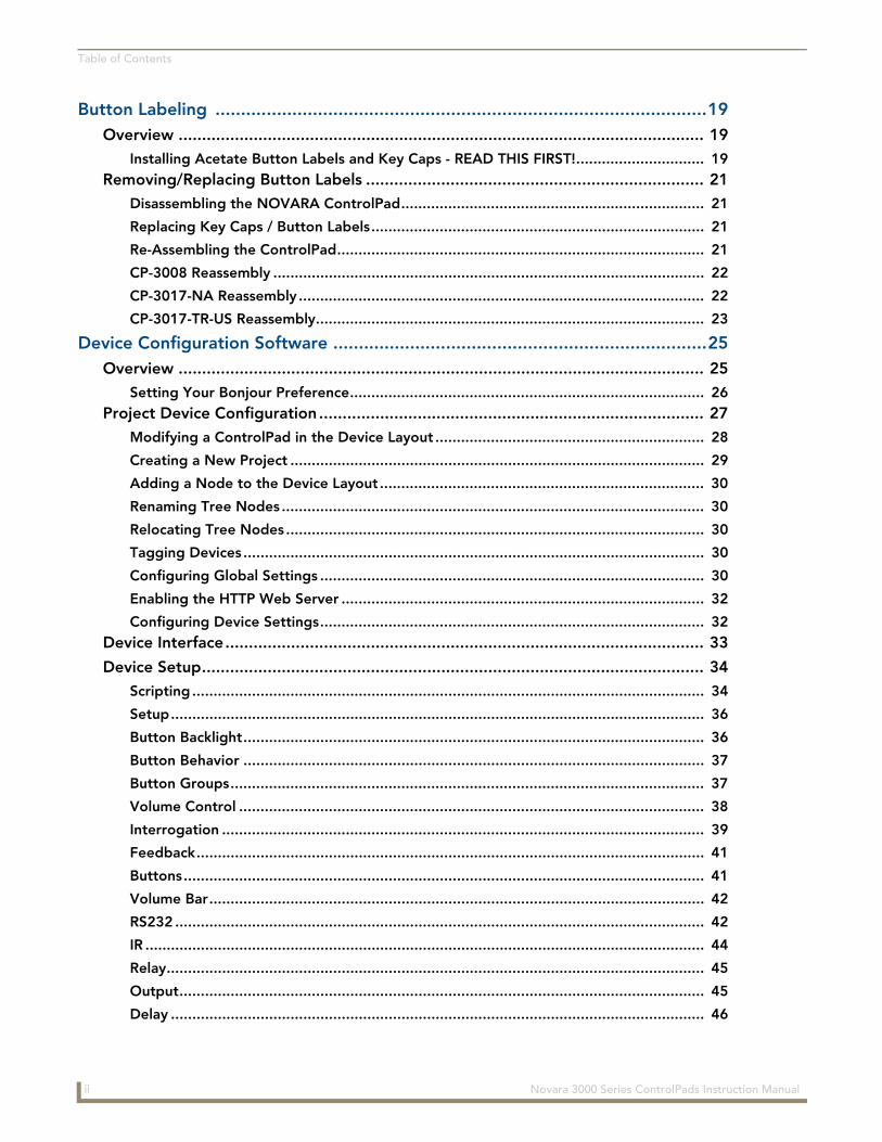
Table of Contents
Button Labeling ................................................................................................19Overview ................................................................................................................ 19
Installing Acetate Button Labels and Key Caps - READ THIS FIRST!.............................. 19
Removing/Replacing Button Labels ........................................................................ 21
Disassembling the NOVARA ControlPad....................................................................... 21
Replacing Key Caps / Button Labels.............................................................................. 21
Re-Assembling the ControlPad...................................................................................... 21
CP-3008 Reassembly ..................................................................................................... 22
CP-3017-NA Reassembly ............................................................................................... 22
CP-3017-TR-US Reassembly........................................................................................... 23
Device Configuration Software .........................................................................25Overview ................................................................................................................ 25
Setting Your Bonjour Preference................................................................................... 26
Project Device Configuration.................................................................................. 27
Modifying a ControlPad in the Device Layout ............................................................... 28
Creating a New Project ................................................................................................. 29
Adding a Node to the Device Layout ............................................................................ 30
Renaming Tree Nodes ................................................................................................... 30
Relocating Tree Nodes.................................................................................................. 30
Tagging Devices ............................................................................................................ 30
Configuring Global Settings .......................................................................................... 30
Enabling the HTTP Web Server ..................................................................................... 32
Configuring Device Settings.......................................................................................... 32
Device Interface...................................................................................................... 33
Device Setup........................................................................................................... 34
Scripting ........................................................................................................................ 34
Setup............................................................................................................................. 36
Button Backlight............................................................................................................ 36
Button Behavior ............................................................................................................ 37
Button Groups............................................................................................................... 37
Volume Control ............................................................................................................. 38
Interrogation ................................................................................................................. 39
Feedback....................................................................................................................... 41
Buttons.......................................................................................................................... 41
Volume Bar.................................................................................................................... 42
RS232 ............................................................................................................................ 42
IR ................................................................................................................................... 44
Relay.............................................................................................................................. 45
Output........................................................................................................................... 45
Delay ............................................................................................................................. 46
ii Novara 3000 Series ControlPads Instruction Manual

Table of Contents
Lockout Buttons ............................................................................................................ 46
Bank Enable................................................................................................................... 47
Advance Toggle ............................................................................................................ 48
Button Actions and Events ............................................................................................ 50
Programming Virtual Buttons ........................................................................................ 50
Creating a Custom Name for a Button .......................................................................... 50
Inputs ............................................................................................................................ 51
Script Types................................................................................................................... 51
Creating a Boot-Up Script ............................................................................................. 51
Creating a Schedule Script ............................................................................................ 52
Creating a Timeout Script ............................................................................................. 52
Programming a Device .................................................................................................. 53
Device Library Manager.......................................................................................... 54
Device Interrogation Formulas ...................................................................................... 56
Adding a Device to the Device Library.......................................................................... 56
Modifying Devices in the Device Library ....................................................................... 57
Importing a Device Library ............................................................................................ 57
Renaming a Device........................................................................................................ 57
ASCII to Hex Tool .......................................................................................................... 58
Test Command Tool ...................................................................................................... 59
Updating Firmware ................................................................................................. 60
Web Console ....................................................................................................63Overview ................................................................................................................ 63
Changing the Image Logo on the Web Pages ............................................................... 63
Device Information Page ............................................................................................... 64
Remote Control Page .................................................................................................... 64
RMS Configuration ...........................................................................................65Overview ................................................................................................................ 65
Installation Checklist ............................................................................................... 65
Installing the CP-RMS Proxy .......................................................................................... 66
Upgrading the CP-RMS Proxy ....................................................................................... 66
Editing the Configuration File ....................................................................................... 67
Starting the CP-RMS Service ......................................................................................... 67
RMS Control Functions and Macros............................................................................... 68
Device Interrogation ..................................................................................................... 68
iiiNovara 3000 Series ControlPads Instruction Manual

Table of Contents
iv Novara 3000 Series ControlPads Instruction Manual
NOVARA 3000 Series ControlPads
NOVARA 3000 Series ControlPads
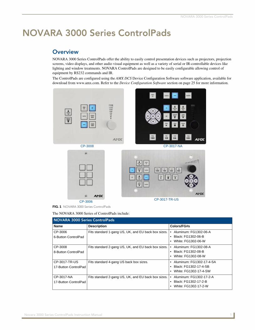
OverviewNOVARA 3000 Series ControlPads offer the ability to easily control presentation devices such as projectors, projection screens, video displays, and other audio visual equipment as well as a variety of serial or IR-controllable devices like lighting and window treatments. NOVARA ControlPads are designed to be easily configurable allowing control of equipment by RS232 commands and IR.
The ControlPads are configured using the AMX DCS Device Configuration Software software application, available for download from www.amx.com. Refer to the Device Configuration Software section on page 25 for more information.
The NOVARA 3000 Series of ControlPads include:
FIG. 1 NOVARA 3000 Series ControlPads
NOVARA 3000 Series ControlPads
Name Description Colors/FG#s
CP-3006
6-Button ControlPad
Fits standard 1-gang US, UK, and EU back box sizes. • Aluminum: FG1302-06-A• Black: FG1302-06-B• White: FG1302-06-W
CP-3008
8-Button ControlPad
Fits standard 2-gang US, UK, and EU back box sizes. • Aluminum: FG1302-08-A• Black: FG1302-08-B• White: FG1302-08-W
CP-3017-TR-US
17-Button ControlPad
Fits standard 4-gang US back box sizes. • Aluminum: FG1302-17-4-SA• Black: FG1302-17-4-SB• White: FG1302-17-4-SW
CP-3017-NA
17-Button ControlPad
Fits standard 2-gang US, UK, and EU back box sizes. • Aluminum: FG1302-17-2-A• Black: FG1302-17-2-B• White: FG1302-17-2-W
CP-3017-TR-US
CP-3017-NACP-3008
CP-3006
1 Novara 3000 Series ControlPads Instruction Manual
NOVARA 3000 Series ControlPads
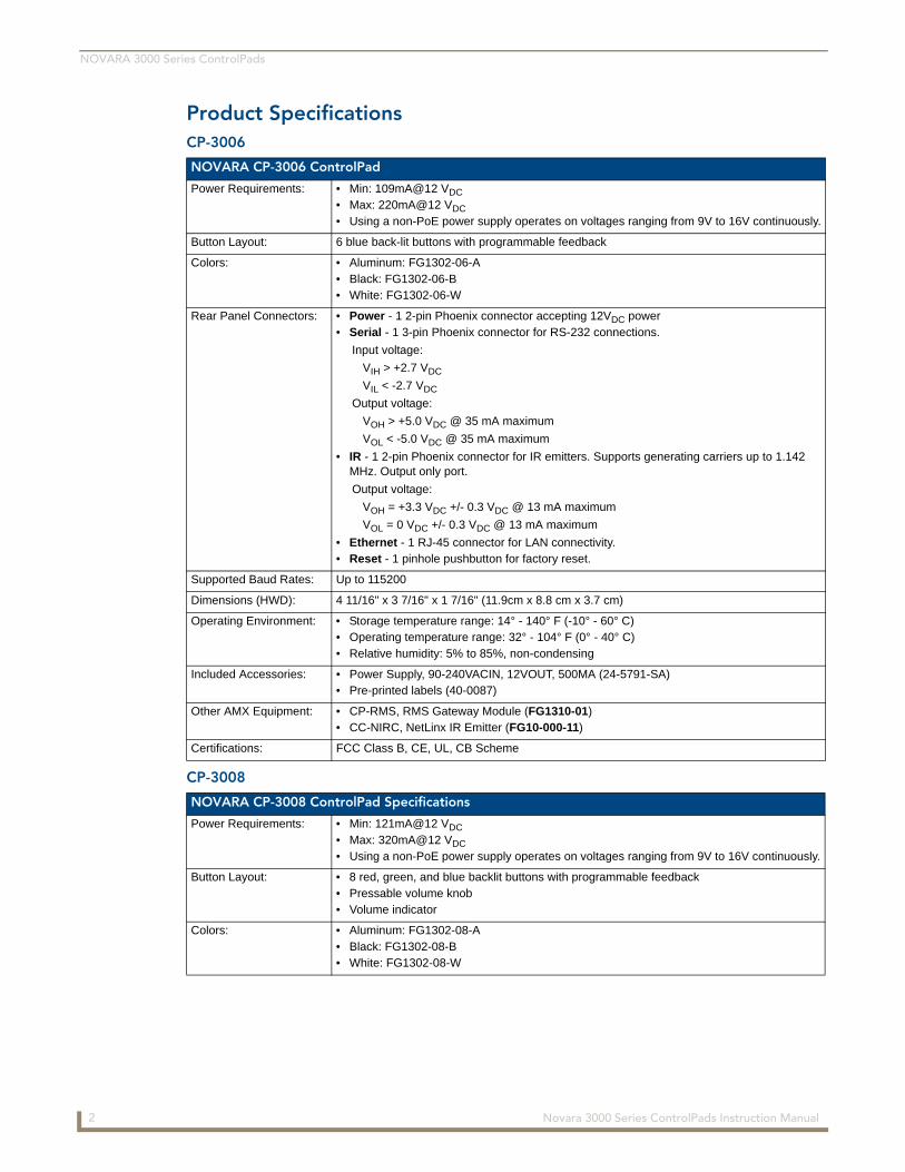
Product SpecificationsCP-3006
CP-3008
NOVARA CP-3006 ControlPad
Power Requirements: • Min: 109mA@12 VDC
• Max: 220mA@12 VDC
• Using a non-PoE power supply operates on voltages ranging from 9V to 16V continuously.
Button Layout: 6 blue back-lit buttons with programmable feedback
Colors: • Aluminum: FG1302-06-A• Black: FG1302-06-B• White: FG1302-06-W
Rear Panel Connectors: • Power - 1 2-pin Phoenix connector accepting 12VDC power• Serial - 1 3-pin Phoenix connector for RS-232 connections.
Input voltage:
VIH > +2.7 VDC
VIL < -2.7 VDC
Output voltage:
VOH > +5.0 VDC @ 35 mA maximum
VOL < -5.0 VDC @ 35 mA maximum
• IR - 1 2-pin Phoenix connector for IR emitters. Supports generating carriers up to 1.142 MHz. Output only port.
Output voltage:
VOH = +3.3 VDC +/- 0.3 VDC @ 13 mA maximum
VOL = 0 VDC +/- 0.3 VDC @ 13 mA maximum
• Ethernet - 1 RJ-45 connector for LAN connectivity.• Reset - 1 pinhole pushbutton for factory reset.
Supported Baud Rates: Up to 115200
Dimensions (HWD): 4 11/16" x 3 7/16" x 1 7/16" (11.9cm x 8.8 cm x 3.7 cm)
Operating Environment: • Storage temperature range: 14° - 140° F (-10° - 60° C)• Operating temperature range: 32° - 104° F (0° - 40° C)• Relative humidity: 5% to 85%, non-condensing
Included Accessories: • Power Supply, 90-240VACIN, 12VOUT, 500MA (24-5791-SA)• Pre-printed labels (40-0087)
Other AMX Equipment: • CP-RMS, RMS Gateway Module (FG1310-01)• CC-NIRC, NetLinx IR Emitter (FG10-000-11)
Certifications: FCC Class B, CE, UL, CB Scheme
NOVARA CP-3008 ControlPad Specifications
Power Requirements: • Min: 121mA@12 VDC
• Max: 320mA@12 VDC
• Using a non-PoE power supply operates on voltages ranging from 9V to 16V continuously.
Button Layout: • 8 red, green, and blue backlit buttons with programmable feedback• Pressable volume knob• Volume indicator
Colors: • Aluminum: FG1302-08-A• Black: FG1302-08-B• White: FG1302-08-W
2 Novara 3000 Series ControlPads Instruction Manual
NOVARA 3000 Series ControlPads
CP-3017-TR-US & -NA
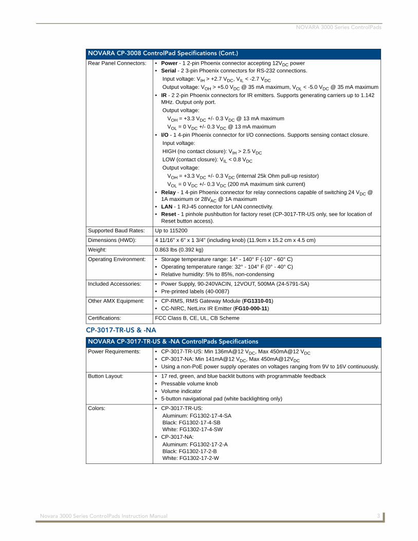
NOVARA CP-3008 ControlPad Specifications (Cont.)
Rear Panel Connectors: • Power - 1 2-pin Phoenix connector accepting 12VDC power• Serial - 2 3-pin Phoenix connectors for RS-232 connections.
Input voltage: VIH > +2.7 VDC, VIL < -2.7 VDC
Output voltage: VOH > +5.0 VDC @ 35 mA maximum, VOL < -5.0 VDC @ 35 mA maximum
• IR - 2 2-pin Phoenix connectors for IR emitters. Supports generating carriers up to 1.142 MHz. Output only port.
Output voltage:
VOH = +3.3 VDC +/- 0.3 VDC @ 13 mA maximum
VOL = 0 VDC +/- 0.3 VDC @ 13 mA maximum
• I/O - 1 4-pin Phoenix connector for I/O connections. Supports sensing contact closure.
Input voltage:
HIGH (no contact closure): VIH > 2.5 VDC
LOW (contact closure): VIL < 0.8 VDC
Output voltage:
VOH = +3.3 VDC +/- 0.3 VDC (internal 25k Ohm pull-up resistor)
VOL = 0 VDC +/- 0.3 VDC (200 mA maximum sink current)
• Relay - 1 4-pin Phoenix connector for relay connections capable of switching 24 VDC @ 1A maximum or 28VAC @ 1A maximum
• LAN - 1 RJ-45 connector for LAN connectivity.• Reset - 1 pinhole pushbutton for factory reset (CP-3017-TR-US only, see for location of
Reset button access).
Supported Baud Rates: Up to 115200
Dimensions (HWD): 4 11/16" x 6" x 1 3/4" (including knob) (11.9cm x 15.2 cm x 4.5 cm)
Weight: 0.863 lbs (0.392 kg)
Operating Environment: • Storage temperature range: 14° - 140° F (-10° - 60° C)• Operating temperature range: 32° - 104° F (0° - 40° C)• Relative humidity: 5% to 85%, non-condensing
Included Accessories: • Power Supply, 90-240VACIN, 12VOUT, 500MA (24-5791-SA)• Pre-printed labels (40-0087)
Other AMX Equipment: • CP-RMS, RMS Gateway Module (FG1310-01)• CC-NIRC, NetLinx IR Emitter (FG10-000-11)
Certifications: FCC Class B, CE, UL, CB Scheme
NOVARA CP-3017-TR-US & -NA ControlPads Specifications
Power Requirements: • CP-3017-TR-US: Min 136mA@12 VDC, Max 450mA@12 VDC
• CP-3017-NA: Min 141mA@12 VDC, Max 450mA@12VDC
• Using a non-PoE power supply operates on voltages ranging from 9V to 16V continuously.
Button Layout: • 17 red, green, and blue backlit buttons with programmable feedback• Pressable volume knob• Volume indicator• 5-button navigational pad (white backlighting only)
Colors: • CP-3017-TR-US:Aluminum: FG1302-17-4-SABlack: FG1302-17-4-SBWhite: FG1302-17-4-SW
• CP-3017-NA:Aluminum: FG1302-17-2-ABlack: FG1302-17-2-BWhite: FG1302-17-2-W
3 Novara 3000 Series ControlPads Instruction Manual
NOVARA 3000 Series ControlPads
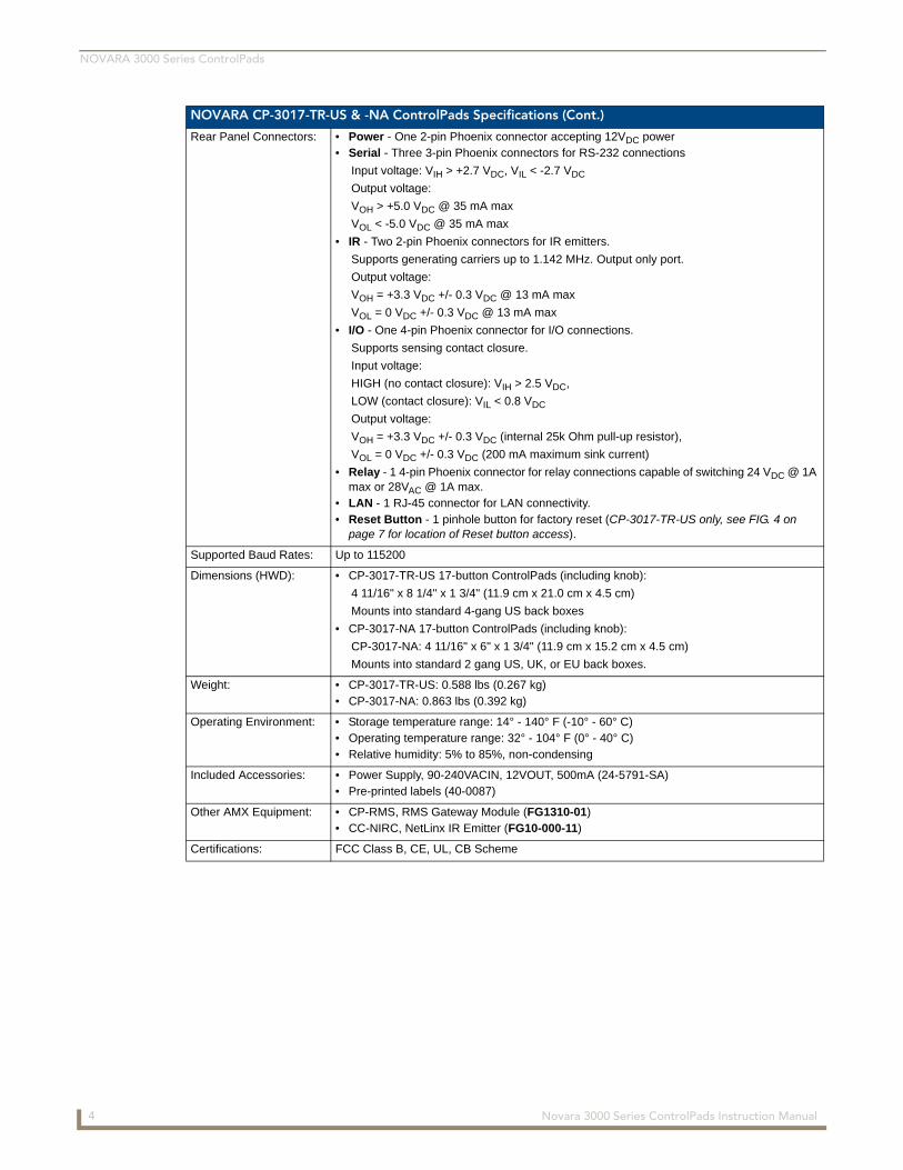
NOVARA CP-3017-TR-US & -NA ControlPads Specifications (Cont.)
Rear Panel Connectors: • Power - One 2-pin Phoenix connector accepting 12VDC power• Serial - Three 3-pin Phoenix connectors for RS-232 connections
Input voltage: VIH > +2.7 VDC, VIL < -2.7 VDC
Output voltage:
VOH > +5.0 VDC @ 35 mA max
VOL < -5.0 VDC @ 35 mA max
• IR - Two 2-pin Phoenix connectors for IR emitters.
Supports generating carriers up to 1.142 MHz. Output only port.
Output voltage:
VOH = +3.3 VDC +/- 0.3 VDC @ 13 mA max
VOL = 0 VDC +/- 0.3 VDC @ 13 mA max
• I/O - One 4-pin Phoenix connector for I/O connections.
Supports sensing contact closure.
Input voltage:
HIGH (no contact closure): VIH > 2.5 VDC,
LOW (contact closure): VIL < 0.8 VDC
Output voltage:
VOH = +3.3 VDC +/- 0.3 VDC (internal 25k Ohm pull-up resistor),
VOL = 0 VDC +/- 0.3 VDC (200 mA maximum sink current)
• Relay - 1 4-pin Phoenix connector for relay connections capable of switching 24 VDC @ 1A max or 28VAC @ 1A max.
• LAN - 1 RJ-45 connector for LAN connectivity.• Reset Button - 1 pinhole button for factory reset (CP-3017-TR-US only, see FIG. 4 on
page 7 for location of Reset button access).
Supported Baud Rates: Up to 115200
Dimensions (HWD): • CP-3017-TR-US 17-button ControlPads (including knob):
4 11/16" x 8 1/4" x 1 3/4" (11.9 cm x 21.0 cm x 4.5 cm)
Mounts into standard 4-gang US back boxes
• CP-3017-NA 17-button ControlPads (including knob):
CP-3017-NA: 4 11/16" x 6" x 1 3/4" (11.9 cm x 15.2 cm x 4.5 cm)
Mounts into standard 2 gang US, UK, or EU back boxes.
Weight: • CP-3017-TR-US: 0.588 lbs (0.267 kg)• CP-3017-NA: 0.863 lbs (0.392 kg)
Operating Environment: • Storage temperature range: 14° - 140° F (-10° - 60° C)• Operating temperature range: 32° - 104° F (0° - 40° C)• Relative humidity: 5% to 85%, non-condensing
Included Accessories: • Power Supply, 90-240VACIN, 12VOUT, 500mA (24-5791-SA)• Pre-printed labels (40-0087)
Other AMX Equipment: • CP-RMS, RMS Gateway Module (FG1310-01)• CC-NIRC, NetLinx IR Emitter (FG10-000-11)
Certifications: FCC Class B, CE, UL, CB Scheme
4 Novara 3000 Series ControlPads Instruction Manual

NOVARA 3000 Series ControlPads
Mounting Specifications - 6-Button ControlPadsCP-3006 CP-3006 6-button keypads mount onto standard 1 gang US, UK, or EU back boxes.
FIG. 2 CP-3006 dimensions
5 Novara 3000 Series ControlPads Instruction Manual
NOVARA 3000 Series ControlPads
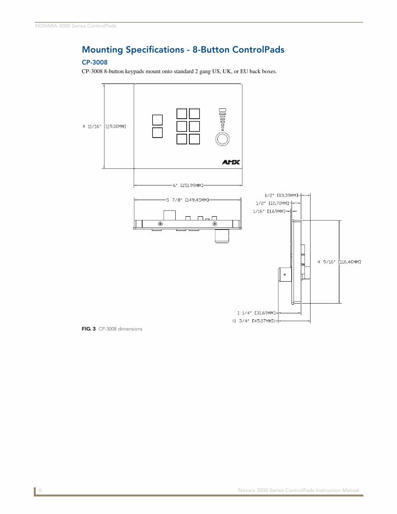
Mounting Specifications - 8-Button ControlPadsCP-3008 CP-3008 8-button keypads mount onto standard 2 gang US, UK, or EU back boxes.
FIG. 3 CP-3008 dimensions
6 Novara 3000 Series ControlPads Instruction Manual
NOVARA 3000 Series ControlPads
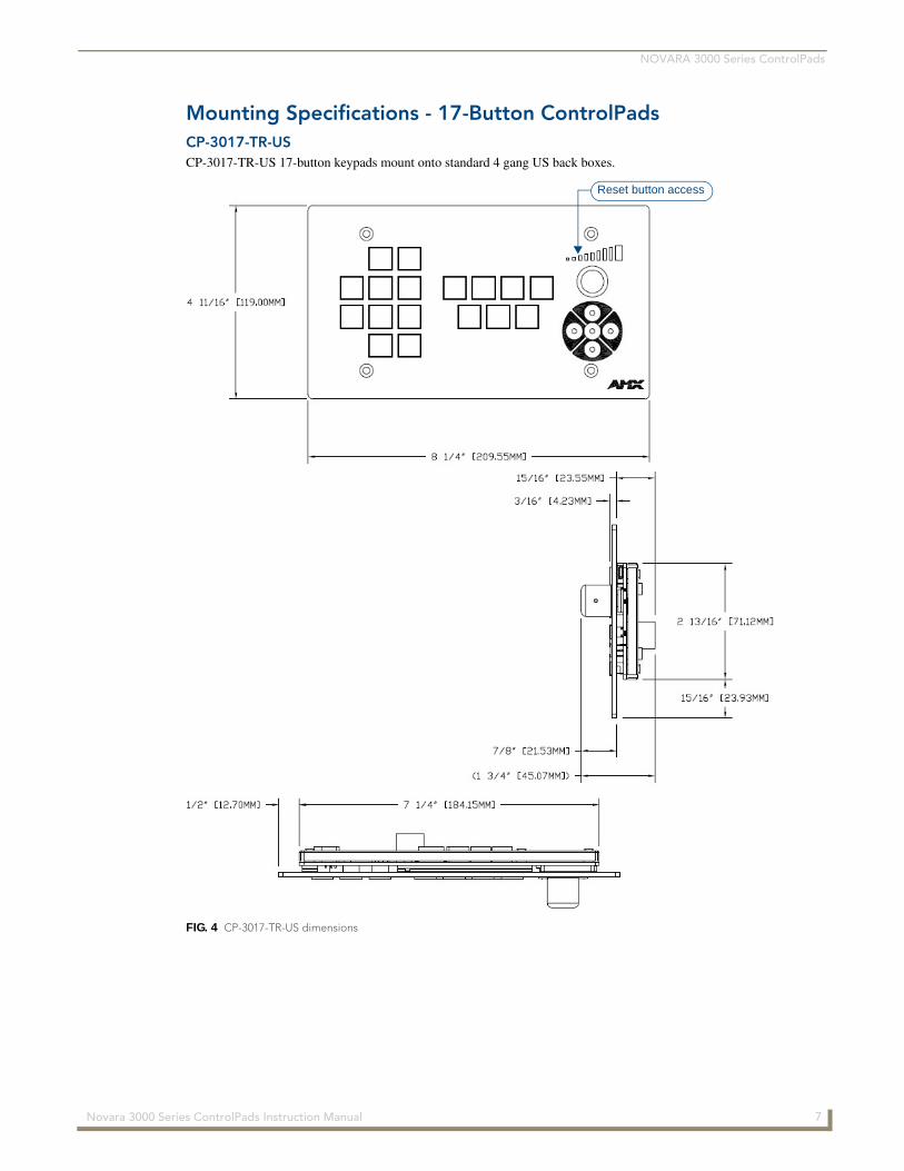
Mounting Specifications - 17-Button ControlPadsCP-3017-TR-USCP-3017-TR-US 17-button keypads mount onto standard 4 gang US back boxes.
FIG. 4 CP-3017-TR-US dimensions
Reset button access
7 Novara 3000 Series ControlPads Instruction Manual
NOVARA 3000 Series ControlPads
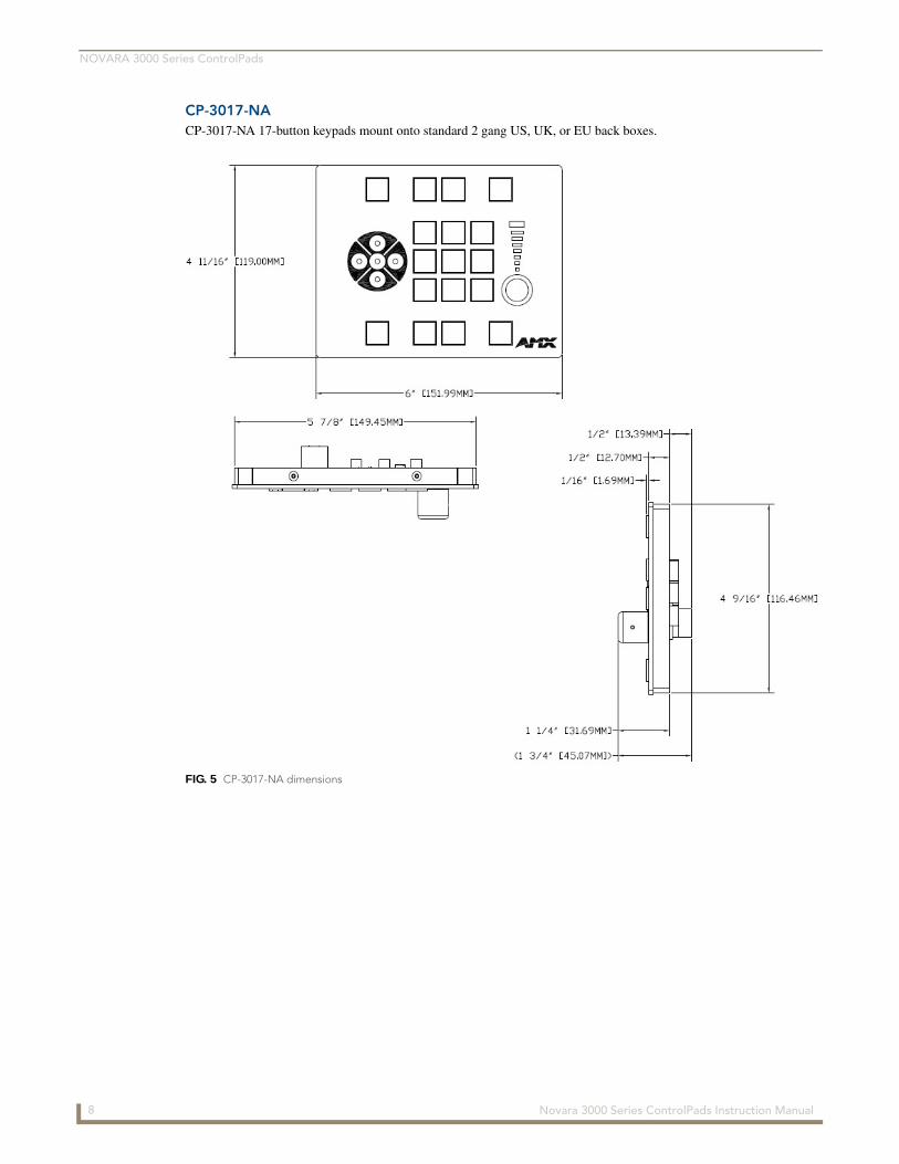
CP-3017-NACP-3017-NA 17-button keypads mount onto standard 2 gang US, UK, or EU back boxes.
FIG. 5 CP-3017-NA dimensions
8 Novara 3000 Series ControlPads Instruction Manual
NOVARA 3000 Series ControlPads
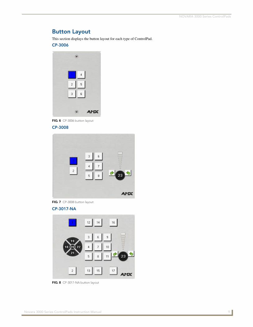
Button LayoutThis section displays the button layout for each type of ControlPad.
CP-3006
CP-3008
CP-3017-NA
FIG. 6 CP-3006 button layout
FIG. 7 CP-3008 button layout
FIG. 8 CP-3017-NA button layout
9 Novara 3000 Series ControlPads Instruction Manual
NOVARA 3000 Series ControlPads
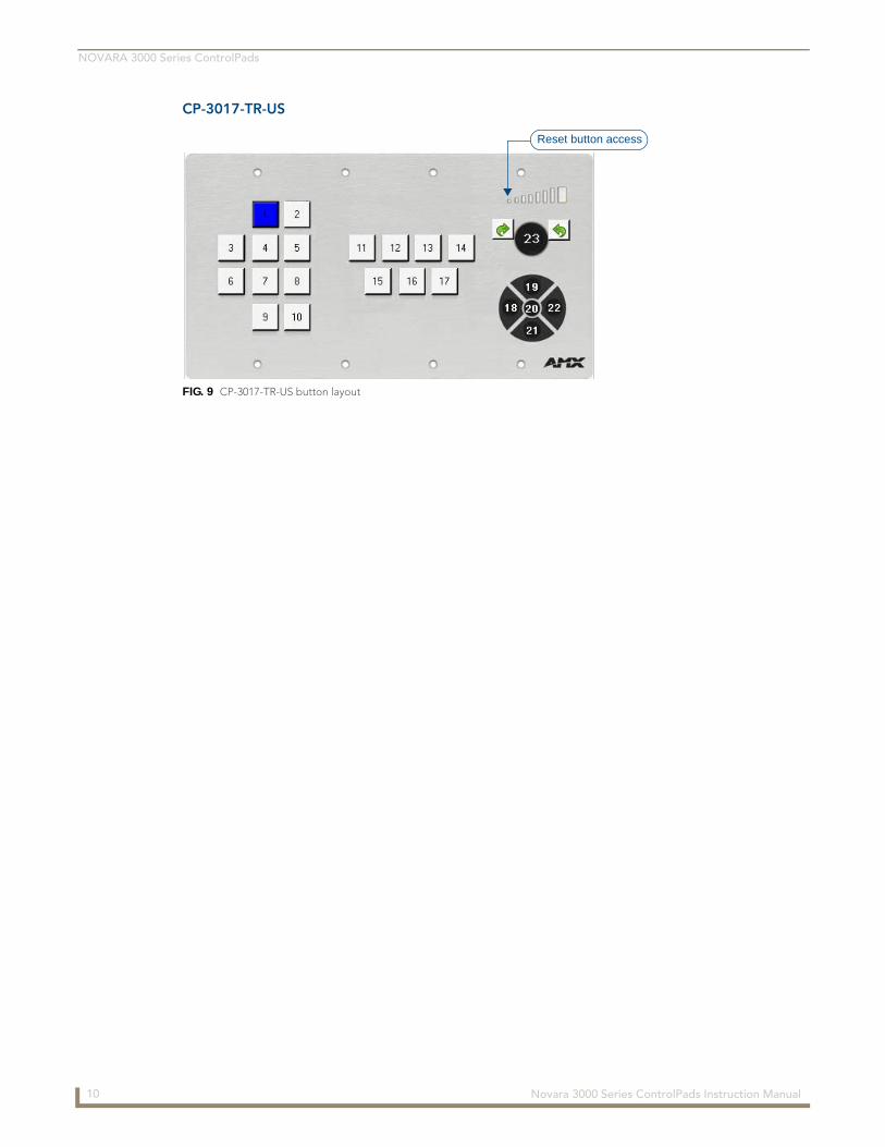
CP-3017-TR-US
FIG. 9 CP-3017-TR-US button layout
Reset button access
10 Novara 3000 Series ControlPads Instruction Manual
Wiring and Device Connections
Wiring and Device Connections
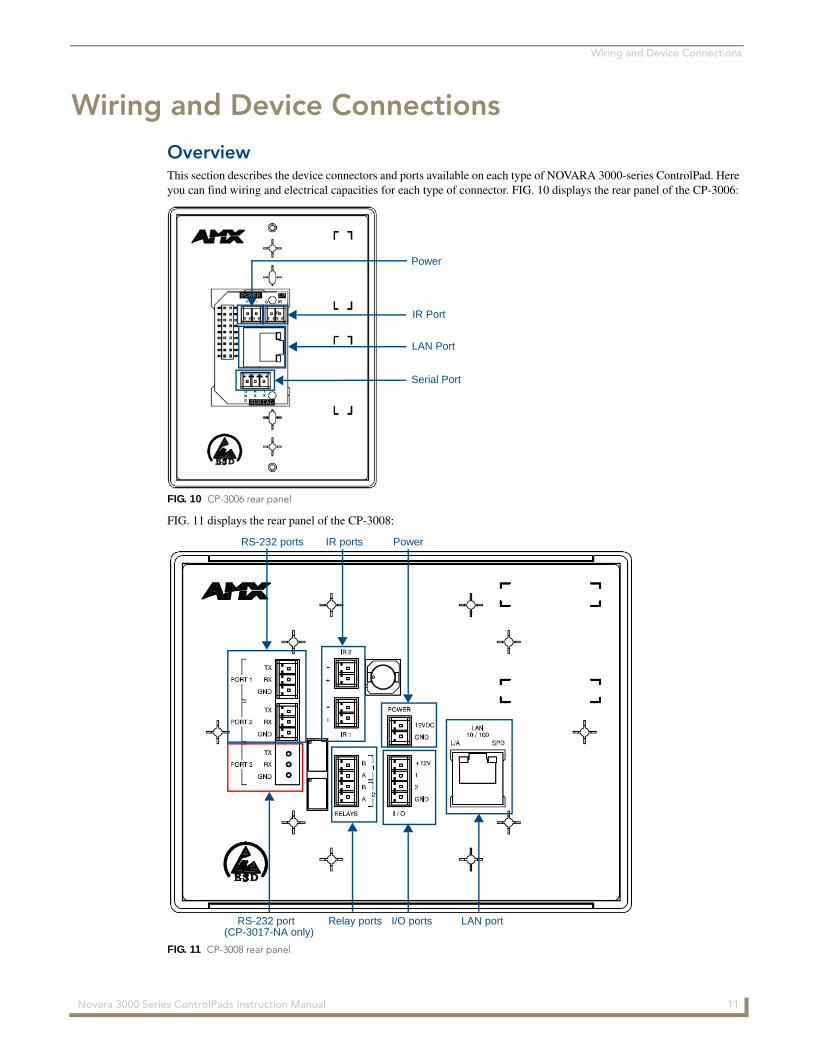
OverviewThis section describes the device connectors and ports available on each type of NOVARA 3000-series ControlPad. Here you can find wiring and electrical capacities for each type of connector. FIG. 10 displays the rear panel of the CP-3006:
FIG. 11 displays the rear panel of the CP-3008:
FIG. 10 CP-3006 rear panel
FIG. 11 CP-3008 rear panel
GND
RX
TX
+ - POWER IR
IR
G
G
SERIAL
Power
IR Port
LAN Port
Serial Port
RS-232 ports IR ports Power
Relay ports I/O ports LAN portRS-232 port(CP-3017-NA only)
11 Novara 3000 Series ControlPads Instruction Manual
Wiring and Device Connections
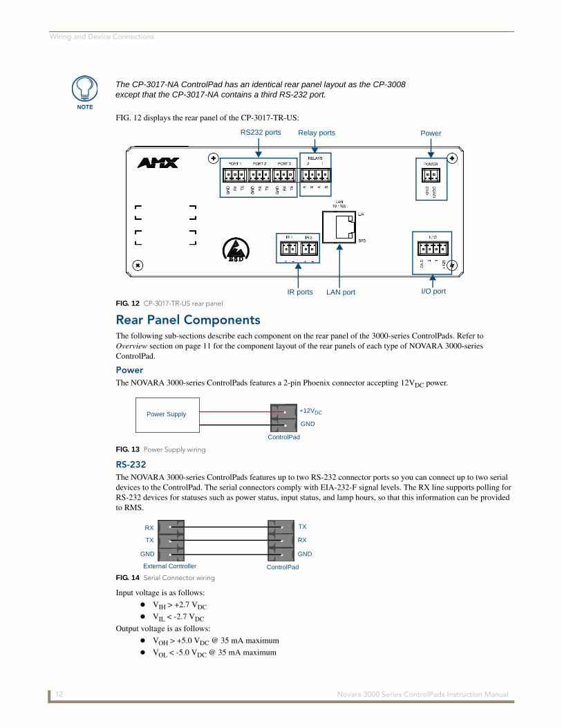
FIG. 12 displays the rear panel of the CP-3017-TR-US:
Rear Panel ComponentsThe following sub-sections describe each component on the rear panel of the 3000-series ControlPads. Refer to Overview section on page 11 for the component layout of the rear panels of each type of NOVARA 3000-series ControlPad.
PowerThe NOVARA 3000-series ControlPads features a 2-pin Phoenix connector accepting 12VDC power.
RS-232The NOVARA 3000-series ControlPads features up to two RS-232 connector ports so you can connect up to two serial devices to the ControlPad. The serial connectors comply with EIA-232-F signal levels. The RX line supports polling for RS-232 devices for statuses such as power status, input status, and lamp hours, so that this information can be provided to RMS.
Input voltage is as follows:
VIH > +2.7 VDC
VIL < -2.7 VDC
Output voltage is as follows:
VOH > +5.0 VDC @ 35 mA maximum
VOL < -5.0 VDC @ 35 mA maximum
The CP-3017-NA ControlPad has an identical rear panel layout as the CP-3008 except that the CP-3017-NA contains a third RS-232 port.
FIG. 12 CP-3017-TR-US rear panel
FIG. 13 Power Supply wiring
FIG. 14 Serial Connector wiring
RS232 ports Relay ports Power
IR ports LAN port I/O port
Power Supply +12VDC
GND
ControlPad
RX
ControlPad
TX
GNDGND
RX
TX
External Controller
12 Novara 3000 Series ControlPads Instruction Manual
Wiring and Device Connections
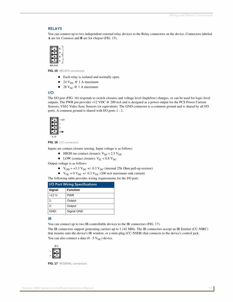
RELAYSYou can connect up to two independent external relay devices to the Relay connectors on the device. Connectors labeled A are for Common and B are for Output (FIG. 15).
Each relay is isolated and normally open.
24 VDC @ 1 A maximum
28 VAC @ 1 A maximum
I/OThe I/O port (FIG. 16) responds to switch closures and voltage level (high/low) changes, or can be used for logic-level outputs. The PWR pin provides +12 VDC @ 200 mA and is designed as a power output for the PCS Power Current Sensors, VSS2 Video Sync Sensors (or equivalent). The GND connector is a common ground and is shared by all I/O ports. A common ground is shared with I/O ports 1 - 2.
Inputs are contact closure sensing. Input voltage is as follows:
HIGH (no contact closure): VIH > 2.5 VDC
LOW (contact closure): VIL < 0.8 VDC
Output voltage is as follows:
VOH = +3.3 VDC +/- 0.3 VDC (internal 25k Ohm pull-up resistor)
VOL = 0 VDC +/- 0.3 VDC (200 mA maximum sink current)
The following table provides wiring requirements for the I/O port:
IRYou can connect up to two IR-controllable devices to the IR connectors (FIG. 17).
The IR connectors support generating carriers up to 1.142 MHz. The IR connectors accept an IR Emitter (CC-NIRC) that mounts onto the device's IR window, or a mini-plug (CC-NSER) that connects to the device's control jack.
You can also connect a data (0 - 5 VDC) device.
FIG. 15 RELAYS connectors
FIG. 16 I/O connectors
I/O Port Wiring Specifications
Signal Function
+12 V: PWR
1: Output
2: Output
GND: Signal GND
FIG. 17 IR/SERIAL connectors
13 Novara 3000 Series ControlPads Instruction Manual
Wiring and Device Connections
Output only port. Output voltage is as follows:
VOH = +3.3 VDC +/- 0.3 VDC @ 13 mA maximum
VOL = 0 VDC +/- 0.3 VDC @ 13 mA maximum
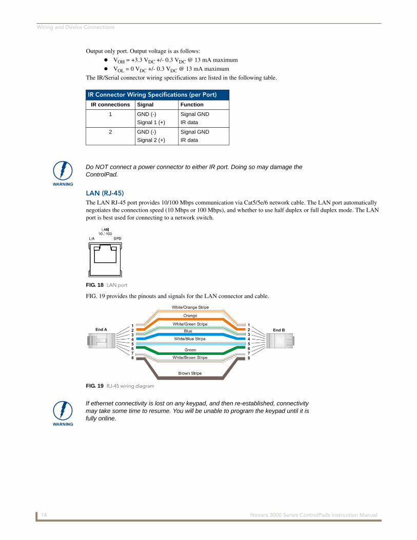
The IR/Serial connector wiring specifications are listed in the following table.
LAN (RJ-45)The LAN RJ-45 port provides 10/100 Mbps communication via Cat5/5e/6 network cable. The LAN port automatically negotiates the connection speed (10 Mbps or 100 Mbps), and whether to use half duplex or full duplex mode. The LAN port is best used for connecting to a network switch.
FIG. 19 provides the pinouts and signals for the LAN connector and cable.
IR Connector Wiring Specifications (per Port)
IR connections Signal Function
1 GND (-)
Signal 1 (+)
Signal GND
IR data
2 GND (-)
Signal 2 (+)
Signal GND
IR data
Do NOT connect a power connector to either IR port. Doing so may damage the ControlPad.
FIG. 18 LAN port
FIG. 19 RJ-45 wiring diagram
If ethernet connectivity is lost on any keypad, and then re-established, connectivity may take some time to resume. You will be unable to program the keypad until it is fully online.
14 Novara 3000 Series ControlPads Instruction Manual
Wiring and Device Connections
Resetting the ControlPadEach ControlPad features a pinhole Reset pushbutton on the rear on the unit for factory reset. To reset the ControlPad, press and hold in the Reset pushbutton for 10 seconds, then release it. The ControlPad will reset. During factory reset, the backlight turns off for all buttons, but all buttons should be back online after 1-2 minutes. If you do not hold in the reset button for the full 10 seconds, the reset does not occur. (There is no soft reboot with the Reset button, but you can perform a soft reboot from the web pages.)
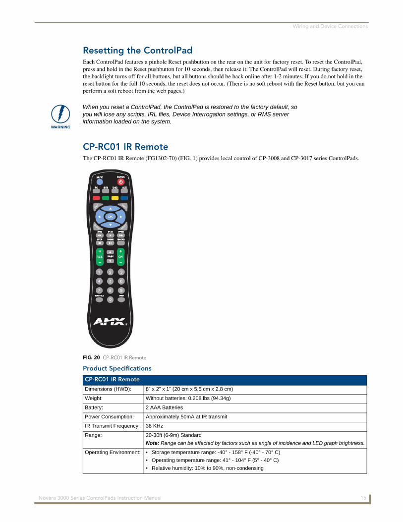
CP-RC01 IR RemoteThe CP-RC01 IR Remote (FG1302-70) (FIG. 1) provides local control of CP-3008 and CP-3017 series ControlPads.
Product Specifications
When you reset a ControlPad, the ControlPad is restored to the factory default, so you will lose any scripts, IRL files, Device Interrogation settings, or RMS server information loaded on the system.
FIG. 20 CP-RC01 IR Remote
CP-RC01 IR Remote
Dimensions (HWD): 8” x 2” x 1” (20 cm x 5.5 cm x 2.8 cm)
Weight: Without batteries: 0.208 lbs (94.34g)
Battery: 2 AAA Batteries
Power Consumption: Approximately 50mA at IR transmit
IR Transmit Frequency: 38 KHz
Range: 20-30ft (6-9m) Standard
Note: Range can be affected by factors such as angle of incidence and LED graph brightness.
Operating Environment: • Storage temperature range: -40° - 158° F (-40° - 70° C)
• Operating temperature range: 41° - 104° F (5° - 40° C)
• Relative humidity: 10% to 90%, non-condensing
15 Novara 3000 Series ControlPads Instruction Manual
Wiring and Device Connections
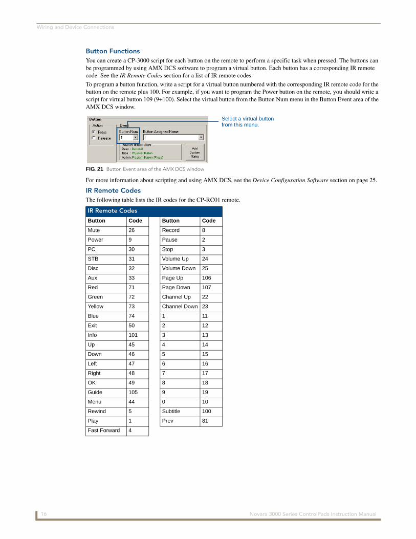
Button FunctionsYou can create a CP-3000 script for each button on the remote to perform a specific task when pressed. The buttons can be programmed by using AMX DCS software to program a virtual button. Each button has a corresponding IR remote code. See the IR Remote Codes section for a list of IR remote codes.
To program a button function, write a script for a virtual button numbered with the corresponding IR remote code for the button on the remote plus 100. For example, if you want to program the Power button on the remote, you should write a script for virtual button 109 (9+100). Select the virtual button from the Button Num menu in the Button Event area of the AMX DCS window.
For more information about scripting and using AMX DCS, see the Device Configuration Software section on page 25.
IR Remote CodesThe following table lists the IR codes for the CP-RC01 remote.
FIG. 21 Button Event area of the AMX DCS window
IR Remote Codes
Button Code Button Code
Mute 26 Record 8
Power 9 Pause 2
PC 30 Stop 3
STB 31 Volume Up 24
Disc 32 Volume Down 25
Aux 33 Page Up 106
Red 71 Page Down 107
Green 72 Channel Up 22
Yellow 73 Channel Down 23
Blue 74 1 11
Exit 50 2 12
Info 101 3 13
Up 45 4 14
Down 46 5 15
Left 47 6 16
Right 48 7 17
OK 49 8 18
Guide 105 9 19
Menu 44 0 10
Rewind 5 Subtitle 100
Play 1 Prev 81
Fast Forward 4
Select a virtual buttonfrom this menu.
16 Novara 3000 Series ControlPads Instruction Manual
Wiring and Device Connections
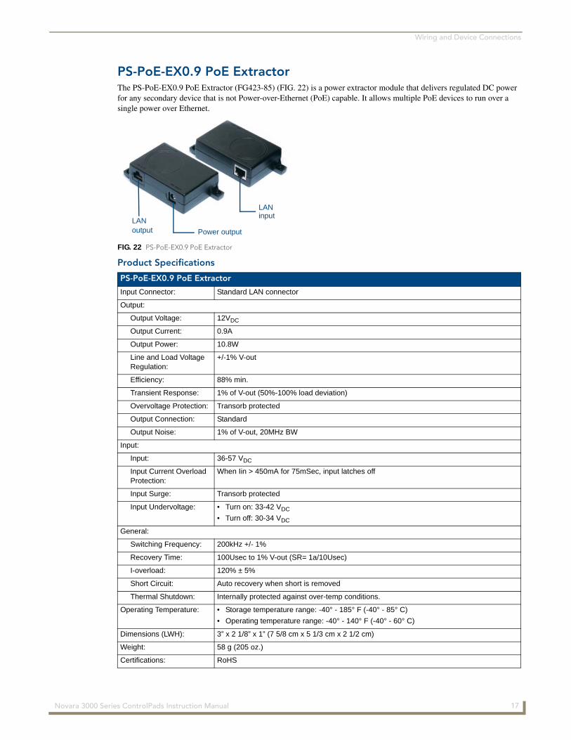
PS-PoE-EX0.9 PoE ExtractorThe PS-PoE-EX0.9 PoE Extractor (FG423-85) (FIG. 22) is a power extractor module that delivers regulated DC power for any secondary device that is not Power-over-Ethernet (PoE) capable. It allows multiple PoE devices to run over a single power over Ethernet.
Product Specifications
FIG. 22 PS-PoE-EX0.9 PoE Extractor
PS-PoE-EX0.9 PoE Extractor
Input Connector: Standard LAN connector
Output:
Output Voltage: 12VDC
Output Current: 0.9A
Output Power: 10.8W
Line and Load Voltage Regulation:
+/-1% V-out
Efficiency: 88% min.
Transient Response: 1% of V-out (50%-100% load deviation)
Overvoltage Protection: Transorb protected
Output Connection: Standard
Output Noise: 1% of V-out, 20MHz BW
Input:
Input: 36-57 VDC
Input Current Overload Protection:
When Iin > 450mA for 75mSec, input latches off
Input Surge: Transorb protected
Input Undervoltage: • Turn on: 33-42 VDC
• Turn off: 30-34 VDC
General:
Switching Frequency: 200kHz +/- 1%
Recovery Time: 100Usec to 1% V-out (SR= 1a/10Usec)
I-overload: 120% ± 5%
Short Circuit: Auto recovery when short is removed
Thermal Shutdown: Internally protected against over-temp conditions.
Operating Temperature: • Storage temperature range: -40° - 185° F (-40° - 85° C)
• Operating temperature range: -40° - 140° F (-40° - 60° C)
Dimensions (LWH): 3” x 2 1/8” x 1” (7 5/8 cm x 5 1/3 cm x 2 1/2 cm)
Weight: 58 g (205 oz.)
Certifications: RoHS
LANoutput Power output
LANinput
17 Novara 3000 Series ControlPads Instruction Manual
Wiring and Device Connections
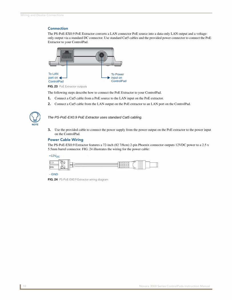
ConnectionThe PS-PoE-EX0.9 PoE Extractor converts a LAN connector PoE source into a data-only LAN output and a voltage-only output via a standard DC connector. Use standard Cat5 cables and the provided power connector to connect the PoE Extractor to your ControlPad.
The following steps describe how to connect the PoE Extractor to your ControlPad.
1. Connect a Cat5 cable from a PoE source to the LAN input on the PoE extractor.
2. Connect a Cat5 cable from the LAN output on the PoE extractor to an LAN port on the ControlPad.
3. Use the provided cable to connect the power supply from the power output on the PoE extractor to the power input on the ControlPad.
Power Cable WiringThe PS-PoE-EX0.9 Extractor features a 72-inch (82 7/8cm) 2-pin Phoenix connector outputs 12VDC power to a 2.5 x 5.5mm barrel connector. FIG. 24 illustrates the wiring for the power cable:
FIG. 23 PoE Extractor outputs
To LANport onControlPad
To Powerinput on ControlPad
The PS-PoE-EX0.9 PoE Extractor uses standard Cat5 cabling.
FIG. 24 PS-PoE-EX0.9 Extractor wiring diagram
- GND
+12VDC
18 Novara 3000 Series ControlPads Instruction Manual

Button Labeling
Button Labeling
OverviewNOVARA ControlPads and KeyPads come with a set of clear plastic Key Caps, which are designed to fit tightly over the pushbuttons, and allow you to place a label on each button according to the requirements of your particular installation.
NOVARA ControlPads and KeyPads also come with a pre-printed acetate sheet with a range of 50 (pre-cut) button label inserts. The button labels provided will accommodate most installations, but it is also possible to print your own button labels on acetate for custom button labeling.
Installing Acetate Button Labels and Key Caps - READ THIS FIRST!
1. Punch out the desired Button Label from the included acetate sheet.
If you have printed your own custom button labels on acetate, cut each button label to fit inside the Key Caps.
Custom button labels must be cut to a 1.14cm (0.45") square to fit securely inside the Key Caps.
The thickness of the acetate used must not exceed .004” (0.10 mm).
2. Place the Key Cap face-down, and insert the Button Label into the bottom of the Key Cap (FIG. 26).
Orient the Button Label inside the Key Cap so that the two clips are located on the left and right sides of the readable text on the Button Label, as indicated in FIG. 26.
Be sure to place the Button Label face-down inside the Key Cap (see FIG. 26), otherwise the label will be seen in reverse once the Key Cap is installed.
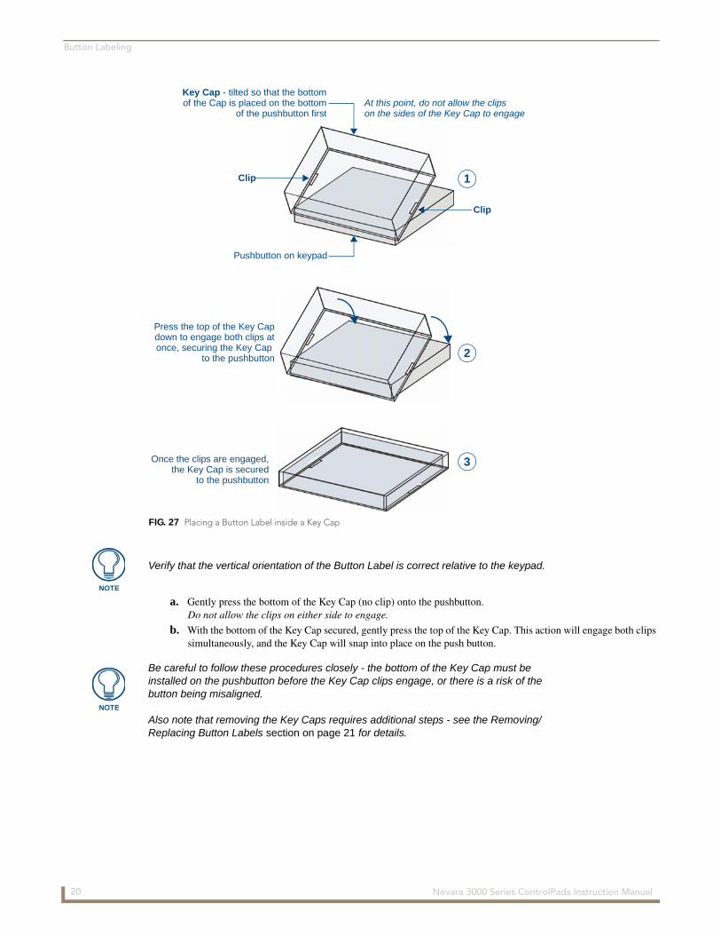
3. Install the Key Cap on the pushbutton (FIG. 27):
FIG. 25 Acetate Button Labels and plastic Key Caps
FIG. 26 Placing a Button Label inside a Key Cap
Acetate sheet of 50 standard Button Labels (pre-cut)
Key Caps
Acetate Button Label (face down)
Key Cap (face-down)
Clip
Clip
19 Novara 3000 Series ControlPads Instruction Manual
Button Labeling
a. Gently press the bottom of the Key Cap (no clip) onto the pushbutton. Do not allow the clips on either side to engage.
b. With the bottom of the Key Cap secured, gently press the top of the Key Cap. This action will engage both clips simultaneously, and the Key Cap will snap into place on the push button.
FIG. 27 Placing a Button Label inside a Key Cap
Clip
Clip
Pushbutton on keypad
Key Cap - tilted so that the bottomof the Cap is placed on the bottom
of the pushbutton firstAt this point, do not allow the clipson the sides of the Key Cap to engage
Press the top of the Key Capdown to engage both clips atonce, securing the Key Cap
to the pushbutton
Once the clips are engaged,the Key Cap is secured
to the pushbutton
1
2
3
Verify that the vertical orientation of the Button Label is correct relative to the keypad.
Be careful to follow these procedures closely - the bottom of the Key Cap must be installed on the pushbutton before the Key Cap clips engage, or there is a risk of the button being misaligned.
Also note that removing the Key Caps requires additional steps - see the Removing/Replacing Button Labels section on page 21 for details.
20 Novara 3000 Series ControlPads Instruction Manual

Button Labeling
Removing/Replacing Button LabelsThe button labels on NOVARA keypads are acetate inserts that fit inside the Key Caps installed on the pushbuttons. In order to change the inserts, the key caps need to be removed. Removing the Key Caps on NOVARA keypads requires disassembling the keypad, so that they can be accessed through the rear of the faceplate:
Disassembling the NOVARA ControlPad
This procedure requires a Phillips-head screwdriver and a .050" hex driver. This procedure is not necessary with CP-3006 ControlPads.
1. Loosen the knob from the faceplate by using a .050" hex driver in the hole in the side of the knob.
2. Remove the volume knob by unscrewing it from the faceplate.
3. Lift the faceplate away from the rear panel to expose the buttons and circuit board.
Replacing Key Caps / Button LabelsOnce the lower board has been removed, you have full access to the pushbuttons.
1. Insert the acetate Button Label in each Key Cap. Be sure to place the Button Label face-down inside the Key Cap, otherwise the label will be seen in reverse once the Key Cap is installed.
2. Gently replace the Key Cap on the pushbutton:
Verify that the vertical orientation of the Button Label is correct relative to the NOVARA keypad.
Align the Key Cap with the target pushbutton, and gently push the Key Cap down over the pushbutton.
Once seated properly on the pushbutton, the Key Cap will snap into place.
Re-Assembling the ControlPadFollow these steps to re-assemble the keypad.
1. With all button Key Caps in place, put the faceplate over the circuit board.
2. Use the supplied #6 screws to secure the faceplate to the circuit board. There are two screw holes on the top of the faceplate rim, and two on the bottom. Use either the Torx screws or #4 Phillips-head screws to attach the faceplate. Use a Torx driver with a T8 tip for the Torx screws; use a Phillips-head screwdriver for the Phillips-head screws. For CP-3006 and CP-3017-TR-US ControlPads, the screws attach through the holes in the faceplate. See the CP-3008 Reassembly section on page 22, the CP-3017-NA Reassembly section on page 22, and the CP-3017-TR-US Reassembly section on page 23 for visual demonstrations of how to reassemble each type of ControlPad.
3. Reattach the knob to the faceplate and screw it in as far as it can go. You should be able to press the knob as a button for extra functionality.
4. Tighten the knob in place using a .050" hex driver in the hole in the side of the knob.
Steps 3 and 4 do not apply to CP-3006 ControlPads.
Remove power from the NOVARA keypad, and discharge any static electricity from your body by touching a grounded metal object before performing the following steps.
FIG. 28 Placing a Button Label inside a Key Cap
Pushbutton on NOVARA keypad
Key Cap
Acetate Button Label (inside the Key Cap)
21 Novara 3000 Series ControlPads Instruction Manual
Button Labeling
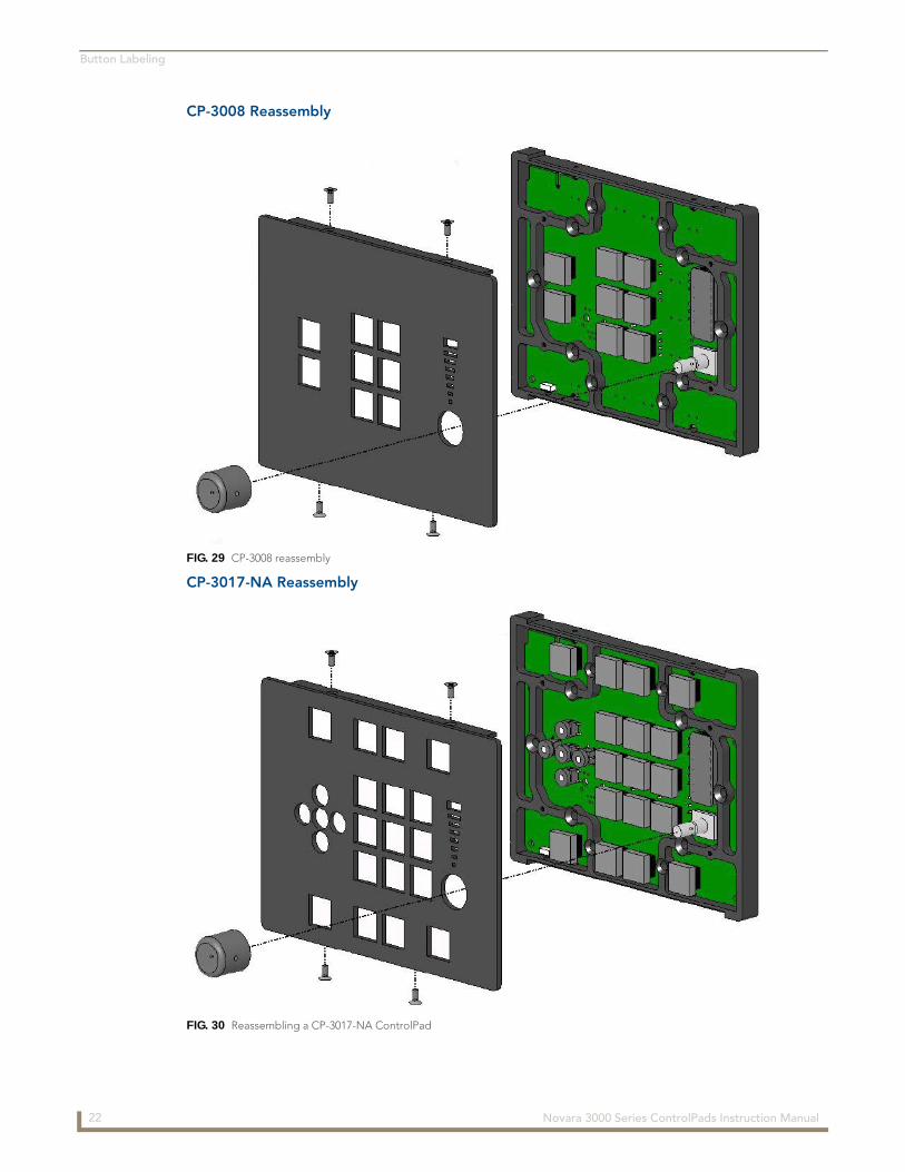
CP-3008 Reassembly
CP-3017-NA Reassembly
FIG. 29 CP-3008 reassembly
FIG. 30 Reassembling a CP-3017-NA ControlPad
22 Novara 3000 Series ControlPads Instruction Manual
Button Labeling
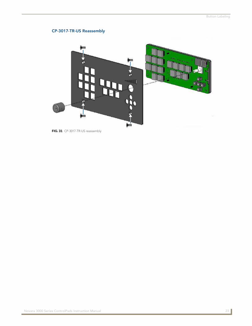
CP-3017-TR-US Reassembly
FIG. 31 CP-3017-TR-US reassembly
23 Novara 3000 Series ControlPads Instruction Manual

Button Labeling
24 Novara 3000 Series ControlPads Instruction Manual
Device Configuration Software
Device Configuration Software
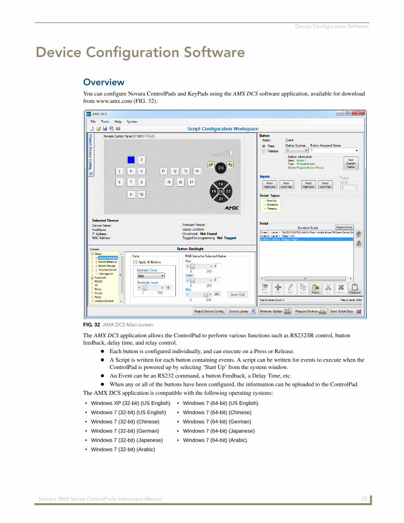
OverviewYou can configure Novara ControlPads and KeyPads using the AMX DCS software application, available for download from www.amx.com (FIG. 32).
The AMX DCS application allows the ControlPad to perform various functions such as RS232/IR control, button feedback, delay time, and relay control.
Each button is configured individually, and can execute on a Press or Release.
A Script is written for each button containing events. A script can be written for events to execute when the ControlPad is powered up by selecting ‘Start Up’ from the system window.
An Event can be an RS232 command, a button Feedback, a Delay Time, etc.
When any or all of the buttons have been configured, the information can be uploaded to the ControlPad.
The AMX DCS application is compatible with the following operating systems:
FIG. 32 AMX DCS Main screen
• Windows XP (32-bit) (US English) • Windows 7 (64-bit) (US English)
• Windows 7 (32-bit) (US English) • Windows 7 (64-bit) (Chinese)
• Windows 7 (32-bit) (Chinese) • Windows 7 (64-bit) (German)
• Windows 7 (32-bit) (German) • Windows 7 (64-bit) (Japanese)
• Windows 7 (32-bit) (Japanese) • Windows 7 (64-bit) (Arabic)
• Windows 7 (32-bit) (Arabic)
25 Novara 3000 Series ControlPads Instruction Manual
Device Configuration Software
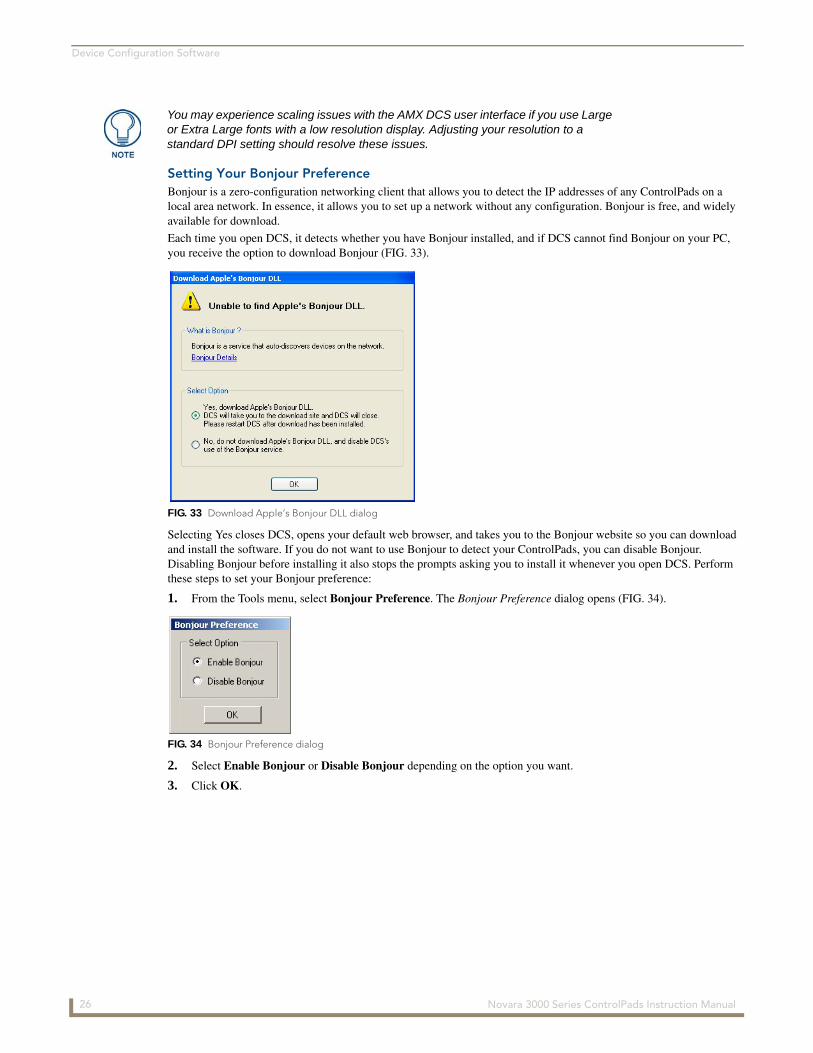
Setting Your Bonjour PreferenceBonjour is a zero-configuration networking client that allows you to detect the IP addresses of any ControlPads on a local area network. In essence, it allows you to set up a network without any configuration. Bonjour is free, and widely available for download.
Each time you open DCS, it detects whether you have Bonjour installed, and if DCS cannot find Bonjour on your PC, you receive the option to download Bonjour (FIG. 33).
Selecting Yes closes DCS, opens your default web browser, and takes you to the Bonjour website so you can download and install the software. If you do not want to use Bonjour to detect your ControlPads, you can disable Bonjour. Disabling Bonjour before installing it also stops the prompts asking you to install it whenever you open DCS. Perform these steps to set your Bonjour preference:
1. From the Tools menu, select Bonjour Preference. The Bonjour Preference dialog opens (FIG. 34).
2. Select Enable Bonjour or Disable Bonjour depending on the option you want.
3. Click OK.
You may experience scaling issues with the AMX DCS user interface if you use Large or Extra Large fonts with a low resolution display. Adjusting your resolution to a standard DPI setting should resolve these issues.
FIG. 33 Download Apple’s Bonjour DLL dialog
FIG. 34 Bonjour Preference dialog
26 Novara 3000 Series ControlPads Instruction Manual
Device Configuration Software
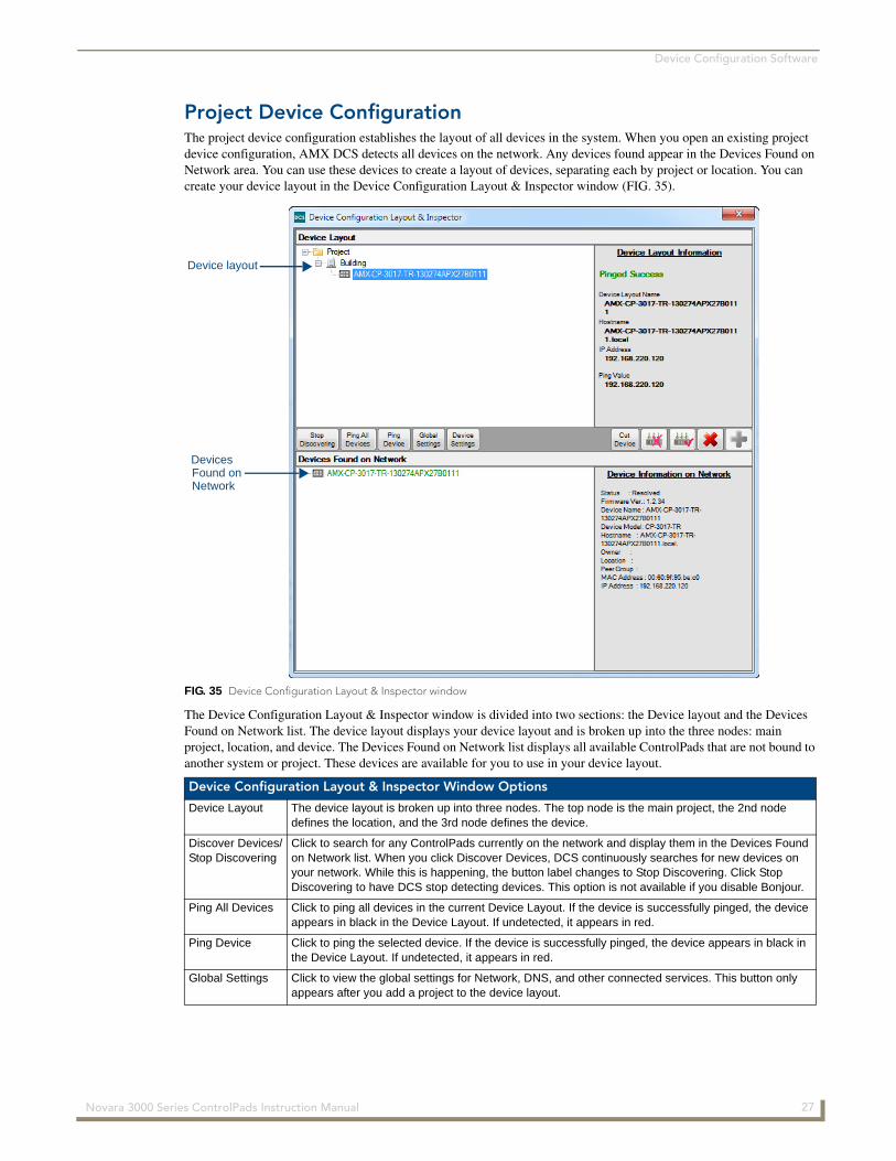
Project Device ConfigurationThe project device configuration establishes the layout of all devices in the system. When you open an existing project device configuration, AMX DCS detects all devices on the network. Any devices found appear in the Devices Found on Network area. You can use these devices to create a layout of devices, separating each by project or location. You can create your device layout in the Device Configuration Layout & Inspector window (FIG. 35).
The Device Configuration Layout & Inspector window is divided into two sections: the Device layout and the Devices Found on Network list. The device layout displays your device layout and is broken up into the three nodes: main project, location, and device. The Devices Found on Network list displays all available ControlPads that are not bound to another system or project. These devices are available for you to use in your device layout.
FIG. 35 Device Configuration Layout & Inspector window
Device Configuration Layout & Inspector Window Options
Device Layout The device layout is broken up into three nodes. The top node is the main project, the 2nd node defines the location, and the 3rd node defines the device.
Discover Devices/Stop Discovering
Click to search for any ControlPads currently on the network and display them in the Devices Found on Network list. When you click Discover Devices, DCS continuously searches for new devices on your network. While this is happening, the button label changes to Stop Discovering. Click Stop Discovering to have DCS stop detecting devices. This option is not available if you disable Bonjour.
Ping All Devices Click to ping all devices in the current Device Layout. If the device is successfully pinged, the device appears in black in the Device Layout. If undetected, it appears in red.
Ping Device Click to ping the selected device. If the device is successfully pinged, the device appears in black in the Device Layout. If undetected, it appears in red.
Global Settings Click to view the global settings for Network, DNS, and other connected services. This button only appears after you add a project to the device layout.
Device layout
DevicesFound onNetwork
27 Novara 3000 Series ControlPads Instruction Manual
Device Configuration Software
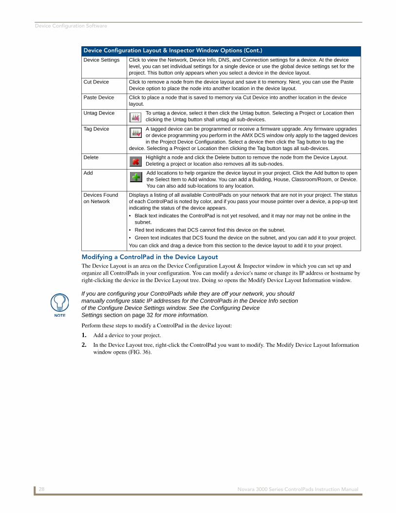
Modifying a ControlPad in the Device LayoutThe Device Layout is an area on the Device Configuration Layout & Inspector window in which you can set up and organize all ControlPads in your configuration. You can modify a device's name or change its IP address or hostname by right-clicking the device in the Device Layout tree. Doing so opens the Modify Device Layout Information window.
Perform these steps to modify a ControlPad in the device layout:
1. Add a device to your project.
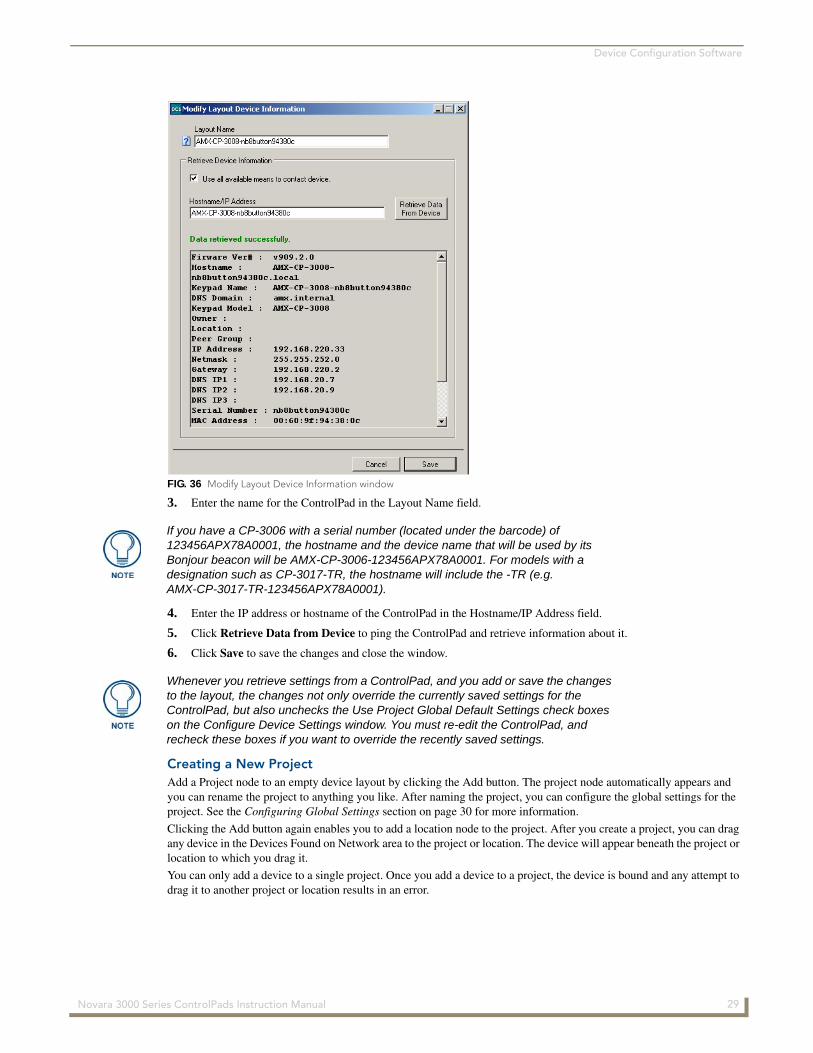
2. In the Device Layout tree, right-click the ControlPad you want to modify. The Modify Device Layout Information window opens (FIG. 36).
Device Configuration Layout & Inspector Window Options (Cont.)
Device Settings Click to view the Network, Device Info, DNS, and Connection settings for a device. At the device level, you can set individual settings for a single device or use the global device settings set for the project. This button only appears when you select a device in the device layout.
Cut Device Click to remove a node from the device layout and save it to memory. Next, you can use the Paste Device option to place the node into another location in the device layout.
Paste Device Click to place a node that is saved to memory via Cut Device into another location in the device layout.
Untag Device To untag a device, select it then click the Untag button. Selecting a Project or Location then clicking the Untag button shall untag all sub-devices.
Tag Device A tagged device can be programmed or receive a firmware upgrade. Any firmware upgrades or device programming you perform in the AMX DCS window only apply to the tagged devices in the Project Device Configuration. Select a device then click the Tag button to tag the
device. Selecting a Project or Location then clicking the Tag button tags all sub-devices.
Delete Highlight a node and click the Delete button to remove the node from the Device Layout. Deleting a project or location also removes all its sub-nodes.
Add Add locations to help organize the device layout in your project. Click the Add button to open the Select Item to Add window. You can add a Building, House, Classroom/Room, or Device. You can also add sub-locations to any location.
Devices Found on Network
Displays a listing of all available ControlPads on your network that are not in your project. The status of each ControlPad is noted by color, and if you pass your mouse pointer over a device, a pop-up text indicating the status of the device appears.
• Black text indicates the ControlPad is not yet resolved, and it may nor may not be online in the subnet.
• Red text indicates that DCS cannot find this device on the subnet.
• Green text indicates that DCS found the device on the subnet, and you can add it to your project.
You can click and drag a device from this section to the device layout to add it to your project.
If you are configuring your ControlPads while they are off your network, you should manually configure static IP addresses for the ControlPads in the Device Info section of the Configure Device Settings window. See the Configuring Device Settings section on page 32 for more information.
28 Novara 3000 Series ControlPads Instruction Manual
Device Configuration Software
3. Enter the name for the ControlPad in the Layout Name field.
4. Enter the IP address or hostname of the ControlPad in the Hostname/IP Address field.
5. Click Retrieve Data from Device to ping the ControlPad and retrieve information about it.
6. Click Save to save the changes and close the window.
Creating a New ProjectAdd a Project node to an empty device layout by clicking the Add button. The project node automatically appears and you can rename the project to anything you like. After naming the project, you can configure the global settings for the project. See the Configuring Global Settings section on page 30 for more information.
Clicking the Add button again enables you to add a location node to the project. After you create a project, you can drag any device in the Devices Found on Network area to the project or location. The device will appear beneath the project or location to which you drag it.
You can only add a device to a single project. Once you add a device to a project, the device is bound and any attempt to drag it to another project or location results in an error.
FIG. 36 Modify Layout Device Information window
If you have a CP-3006 with a serial number (located under the barcode) of 123456APX78A0001, the hostname and the device name that will be used by its Bonjour beacon will be AMX-CP-3006-123456APX78A0001. For models with a designation such as CP-3017-TR, the hostname will include the -TR (e.g. AMX-CP-3017-TR-123456APX78A0001).
Whenever you retrieve settings from a ControlPad, and you add or save the changes to the layout, the changes not only override the currently saved settings for the ControlPad, but also unchecks the Use Project Global Default Settings check boxes on the Configure Device Settings window. You must re-edit the ControlPad, and recheck these boxes if you want to override the recently saved settings.
29 Novara 3000 Series ControlPads Instruction Manual

Device Configuration Software
Adding a Node to the Device LayoutAdd a Project node to an empty device layout by clicking the Add button. The project node automatically appears and you can rename the project to anything you like. After naming the project, you can configure the global settings for the project. See the Configuring Global Settings section on page 30 for more information.
Renaming Tree NodesYou can rename Project and Location nodes by clicking the nodes twice (once for selection and again to rename). You must assign a unique name to each node.
To rename a device, you must change it through the Device settings. Perform these steps to rename a device in your device layout:
1. Add a device to your project.
2. Select the device in the device layout, and click Device Settings. The Configure Device Settings window opens (FIG. 38).
3. Click Device Info in the Content area to display the Device Information options.
4. Enter the device name in the New Device Name field. You can also provide information in the Host Name, Owner, and Location fields if you want.
5. Click Accept. The new device name appears in the device layout.
Relocating Tree NodesLocation and Device nodes can be relocated to applicable area by clicking and dragging the node to its new location within the project. Moving a node also moves its sub-nodes. No node can be added or moved under a device. Project nodes cannot be relocated and must remain on top of the tree.
Tagging DevicesA tagged device can be programmed or receive a firmware upgrade. Any firmware upgrades or device programming you perform in the AMX DCS window only apply to the tagged devices in the Project Device Configuration.
Select a device then click the Tag button to tag the device. Selecting a Project or Location then clicking the Tag button shall tag all sub-devices.
To untag a device, select it then click the Untag button. Selecting a Project or Location then clicking the Untag button shall untag all sub-devices.
When a device is not found on the network, the text label appears bolded red. You cannot tag these devices.
- Indicates a tagged device
- Indicates an untagged device
Configuring Global SettingsAt the project level, you can set global settings for all devices on the project. Click the Global Settings button to access the Configure Global Device Settings window (FIG. 37). The window contains five separate screens with settings for Network, DNS, Connections, NTP, and Web. Click the option you want in the Content area to view or change the settings for each type.
FIG. 37 Configure Global Device Settings Window (Network options)
30 Novara 3000 Series ControlPads Instruction Manual

Device Configuration Software
The following table lists the options for each section of the Configure Global Device Settings window:
Configure Global Device Settings Window Options
Network
Enable DHCP Enables DHCP on all devices when checked. This option is checked by default. This option is checked by default. If you disable this option, you should manually configure static IP addresses for the ControlPads in the Device Info section of the Configure Device Settings window. See the Configuring Device Settings section on page 32 for more information.
Gateway IP Address Enter the gateway IP address in the field provided. This option only applies if you disable DHCP.
Net Mask IP Address Enter the network mask IP address in the field provided. This option only applies if you disable DHCP.
DNS
Enable mDNS Enables Multicast DNS on all devices when checked. This option is checked by default.
Warning: Disabling this option prevents DCS from seeing the device again. DCS will only see the device again after restoring the factory defaults, which causes you to lose all configuration and scripting data.
Domain Suffix Enter the domain suffix in the field provided. This option only applies if you disable DHCP.
DNS IP Enter the IP address of the domain server in the fields provided. You can enter up to three IP addresses in the three individual fields. This option only applies if you disable DHCP.
Connections
Enable RMS Enable RMS on all devices when checked. This option is checked by default.
Preferred RMS ServerIP Address
Enter the IP address of the RMS server in this field.
RMS Peer Group Enter the address of the RMS peer group in this field.
Note: If you set the RMS Peer Group to an empty value, then that ControlPad will disappear from RMS, as the RMS Proxy will no longer see it. If you want to set the RMS Peer Group to an empty value, you must restore the factory defaults for the ControlPad.
RMS Proxy Port Displays the proxy port for the RMS server. This field is view-only.
Enable DCS Enable DCS on all devices when checked. This option is checked by default.
Warning: Disabling this option prevents DCS from seeing the device again. DCS will only see the device again after restoring the factory defaults, which causes you to lose all configuration and scripting data.
DCS Port Displays the port DCS is using. This field is view-only.
NTP
Enable NTP Enables the Network Time Protocol (NTP) on all devices when checked. This option is unchecked by default.
Primary NTP Server Enter or use the menu to select the primary NTP server.
Secondary NTP Server Enter or use the menu to select the secondary NTP server.
Tertiary NTP Server Enter or use the menu to select the tertiary NTP server.
Update Frequency Use the menu to select an update frequency for the NTP server. You can choose from 15 minutes, 30 minutes, 1 hour, 2 hours, 4 hours, and 24 hours.
Time Zone Use the menu to select the NTP time zone.
Enable Daylight Savings
Click this check box to turn on Daylight Savings. When enabled, all options within this area are active. This option is unchecked by default.
Offset Use the hour and minute menus to indicate the amount of the time change when Daylight Savings is active.
Starts Use the available menus to indicate the time when Daylight Savings begins including month, day of the week, week of the month, and time of day.
Ends Use the available menus to indicate the time when Daylight Savings ends including month, day of the week, week of the month, and time of day.
31 Novara 3000 Series ControlPads Instruction Manual
Device Configuration Software
Enabling the HTTP Web ServerPerform these steps to enable the HTTP web server and allow user access to web pages for all devices:
1. Access the Device Configuration Layout & Inspector window (FIG. 35).
2. Click Global Settings. The Configure Global Device Settings window opens (FIG. 37).
3. Click Web.
4. Click Enable HTTP Web Server.
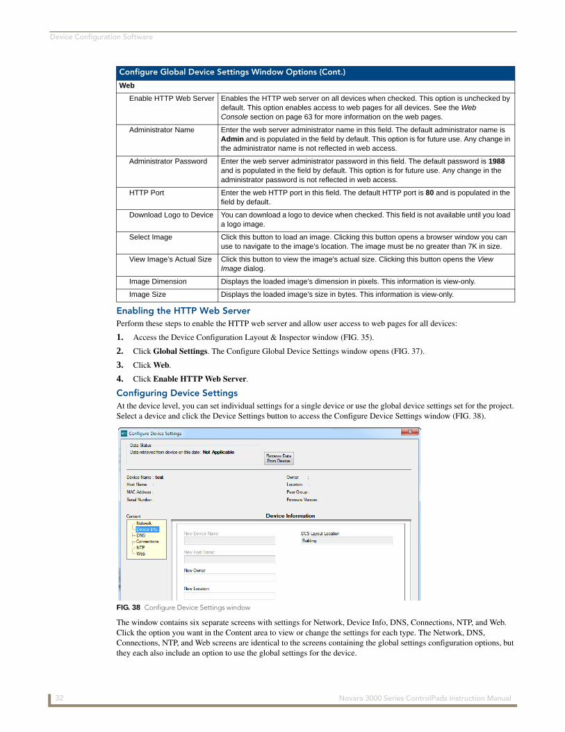
Configuring Device SettingsAt the device level, you can set individual settings for a single device or use the global device settings set for the project. Select a device and click the Device Settings button to access the Configure Device Settings window (FIG. 38).
The window contains six separate screens with settings for Network, Device Info, DNS, Connections, NTP, and Web. Click the option you want in the Content area to view or change the settings for each type. The Network, DNS, Connections, NTP, and Web screens are identical to the screens containing the global settings configuration options, but they each also include an option to use the global settings for the device.
Configure Global Device Settings Window Options (Cont.)
Web
Enable HTTP Web Server Enables the HTTP web server on all devices when checked. This option is unchecked by default. This option enables access to web pages for all devices. See the Web Console section on page 63 for more information on the web pages.
Administrator Name Enter the web server administrator name in this field. The default administrator name is Admin and is populated in the field by default. This option is for future use. Any change in the administrator name is not reflected in web access.
Administrator Password Enter the web server administrator password in this field. The default password is 1988 and is populated in the field by default. This option is for future use. Any change in the administrator password is not reflected in web access.
HTTP Port Enter the web HTTP port in this field. The default HTTP port is 80 and is populated in the field by default.
Download Logo to Device You can download a logo to device when checked. This field is not available until you load a logo image.
Select Image Click this button to load an image. Clicking this button opens a browser window you can use to navigate to the image’s location. The image must be no greater than 7K in size.
View Image’s Actual Size Click this button to view the image's actual size. Clicking this button opens the View Image dialog.
Image Dimension Displays the loaded image’s dimension in pixels. This information is view-only.
Image Size Displays the loaded image’s size in bytes. This information is view-only.
FIG. 38 Configure Device Settings window
32 Novara 3000 Series ControlPads Instruction Manual
Device Configuration Software
The following table lists the options for the Device Info screen. You must configure these options if you disable DHCP in the Configure Global Device Settings window.
The current configuration of the currently selected ControlPad displays at the top of the window. The information that appears includes: Device Name, Host Name, MAC Address, Serial Number, Owner, Location, Peer Group (for RMS), and Firmware Version. Some of these fields may be blank if they have not yet been set, or were cleared during programming.
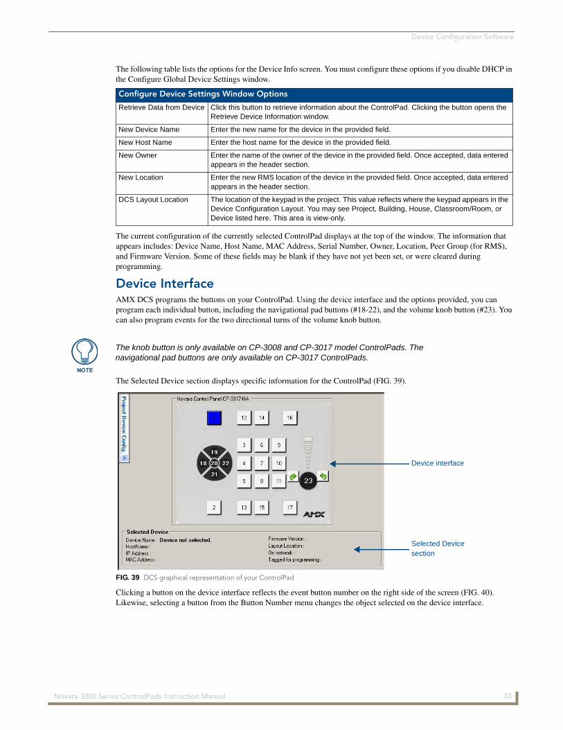
Device InterfaceAMX DCS programs the buttons on your ControlPad. Using the device interface and the options provided, you can program each individual button, including the navigational pad buttons (#18-22), and the volume knob button (#23). You can also program events for the two directional turns of the volume knob button.
The Selected Device section displays specific information for the ControlPad (FIG. 39).
Clicking a button on the device interface reflects the event button number on the right side of the screen (FIG. 40). Likewise, selecting a button from the Button Number menu changes the object selected on the device interface.
Configure Device Settings Window Options
Retrieve Data from Device Click this button to retrieve information about the ControlPad. Clicking the button opens the Retrieve Device Information window.
New Device Name Enter the new name for the device in the provided field.
New Host Name Enter the host name for the device in the provided field.
New Owner Enter the name of the owner of the device in the provided field. Once accepted, data entered appears in the header section.
New Location Enter the new RMS location of the device in the provided field. Once accepted, data entered appears in the header section.
DCS Layout Location The location of the keypad in the project. This value reflects where the keypad appears in the Device Configuration Layout. You may see Project, Building, House, Classroom/Room, or Device listed here. This area is view-only.
The knob button is only available on CP-3008 and CP-3017 model ControlPads. The navigational pad buttons are only available on CP-3017 ControlPads.
FIG. 39 DCS graphical representation of your ControlPad
Selected Devicesection
Device interface
33 Novara 3000 Series ControlPads Instruction Manual
Device Configuration Software
Device SetupThe following sections describe the options available for event scripting for each keypad.
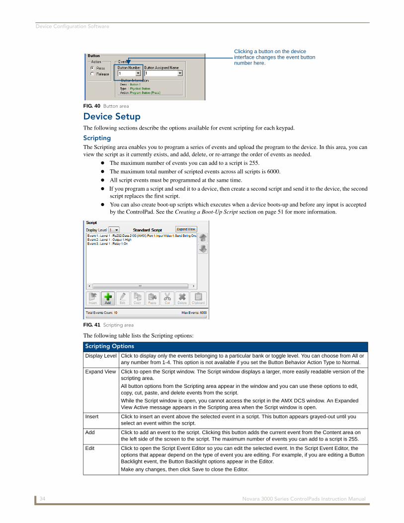
ScriptingThe Scripting area enables you to program a series of events and upload the program to the device. In this area, you can view the script as it currently exists, and add, delete, or re-arrange the order of events as needed.
The maximum number of events you can add to a script is 255.
The maximum total number of scripted events across all scripts is 6000.
All script events must be programmed at the same time.
If you program a script and send it to a device, then create a second script and send it to the device, the second script replaces the first script.
You can also create boot-up scripts which executes when a device boots-up and before any input is accepted by the ControlPad. See the Creating a Boot-Up Script section on page 51 for more information.
The following table lists the Scripting options:
FIG. 40 Button area
FIG. 41 Scripting area
Scripting Options
Display Level Click to display only the events belonging to a particular bank or toggle level. You can choose from All or any number from 1-4. This option is not available if you set the Button Behavior Action Type to Normal.
Expand View Click to open the Script window. The Script window displays a larger, more easily readable version of the scripting area.
All button options from the Scripting area appear in the window and you can use these options to edit, copy, cut, paste, and delete events from the script.
While the Script window is open, you cannot access the script in the AMX DCS window. An Expanded View Active message appears in the Scripting area when the Script window is open.
Insert Click to insert an event above the selected event in a script. This button appears grayed-out until you select an event within the script.
Add Click to add an event to the script. Clicking this button adds the current event from the Content area on the left side of the screen to the script. The maximum number of events you can add to a script is 255.
Edit Click to open the Script Event Editor so you can edit the selected event. In the Script Event Editor, the options that appear depend on the type of event you are editing. For example, if you are editing a Button Backlight event, the Button Backlight options appear in the Editor.
Make any changes, then click Save to close the Editor.
Clicking a button on the deviceinterface changes the event buttonnumber here.
34 Novara 3000 Series ControlPads Instruction Manual
Device Configuration Software
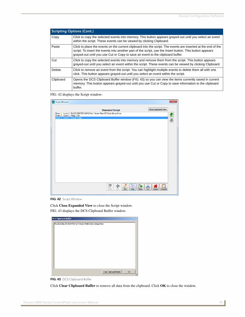
FIG. 42 displays the Script window:
Click Close Expanded View to close the Script window.
FIG. 43 displays the DCS Clipboard Buffer window.
Click Clear Clipboard Buffer to remove all data from the clipboard. Click OK to close the window.
Scripting Options (Cont.)
Copy Click to copy the selected events into memory. This button appears grayed-out until you select an event within the script. These events can be viewed by clicking Clipboard.
Paste Click to place the events on the current clipboard into the script. The events are inserted at the end of the script. To insert the events into another part of the script, use the Insert button. This button appears grayed-out until you use Cut or Copy to save an event to the clipboard buffer.
Cut Click to copy the selected events into memory and remove them from the script. This button appears grayed-out until you select an event within the script. These events can be viewed by clicking Clipboard.
Delete Click to remove an event from the script. You can highlight multiple events to delete them all with one click. This button appears grayed-out until you select an event within the script.
Clipboard Opens the DCS Clipboard Buffer window (FIG. 43) so you can view the items currently saved in current memory. This button appears grayed-out until you use Cut or Copy to save information to the clipboard buffer.
FIG. 42 Script Window
FIG. 43 DCS Clipboard Buffer
35 Novara 3000 Series ControlPads Instruction Manual
Device Configuration Software
SetupSetup contains five options for your ControlPad: Button Backlight, Button Behavior, Button Groups, Volume Control, and Interrogation. Click the plus sign (+) beside Setup to expand or collapse the available options.
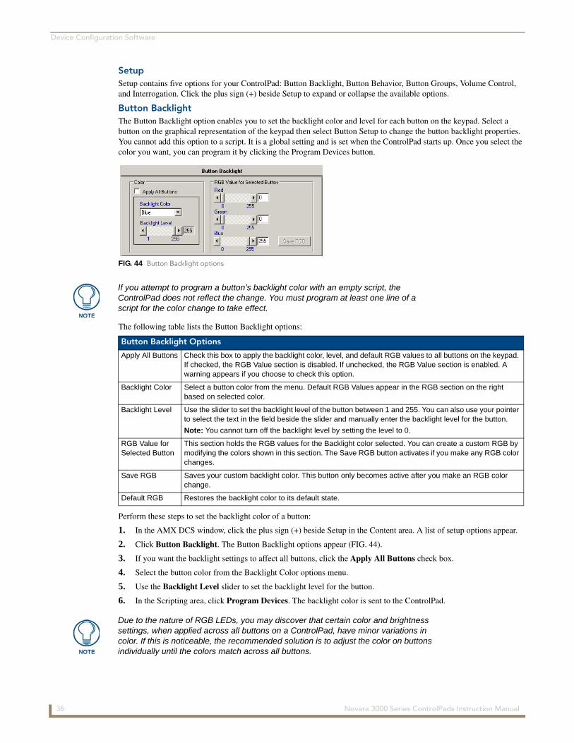
Button BacklightThe Button Backlight option enables you to set the backlight color and level for each button on the keypad. Select a button on the graphical representation of the keypad then select Button Setup to change the button backlight properties. You cannot add this option to a script. It is a global setting and is set when the ControlPad starts up. Once you select the color you want, you can program it by clicking the Program Devices button.
The following table lists the Button Backlight options:
Perform these steps to set the backlight color of a button:
1. In the AMX DCS window, click the plus sign (+) beside Setup in the Content area. A list of setup options appear.
2. Click Button Backlight. The Button Backlight options appear (FIG. 44).
3. If you want the backlight settings to affect all buttons, click the Apply All Buttons check box.
4. Select the button color from the Backlight Color options menu.
5. Use the Backlight Level slider to set the backlight level for the button.
6. In the Scripting area, click Program Devices. The backlight color is sent to the ControlPad.
FIG. 44 Button Backlight options
If you attempt to program a button’s backlight color with an empty script, the ControlPad does not reflect the change. You must program at least one line of a script for the color change to take effect.
Button Backlight Options
Apply All Buttons Check this box to apply the backlight color, level, and default RGB values to all buttons on the keypad. If checked, the RGB Value section is disabled. If unchecked, the RGB Value section is enabled. A warning appears if you choose to check this option.
Backlight Color Select a button color from the menu. Default RGB Values appear in the RGB section on the right based on selected color.
Backlight Level Use the slider to set the backlight level of the button between 1 and 255. You can also use your pointer to select the text in the field beside the slider and manually enter the backlight level for the button.
Note: You cannot turn off the backlight level by setting the level to 0.
RGB Value for Selected Button
This section holds the RGB values for the Backlight color selected. You can create a custom RGB by modifying the colors shown in this section. The Save RGB button activates if you make any RGB color changes.
Save RGB Saves your custom backlight color. This button only becomes active after you make an RGB color change.
Default RGB Restores the backlight color to its default state.
Due to the nature of RGB LEDs, you may discover that certain color and brightness settings, when applied across all buttons on a ControlPad, have minor variations in color. If this is noticeable, the recommended solution is to adjust the color on buttons individually until the colors match across all buttons.
36 Novara 3000 Series ControlPads Instruction Manual
Device Configuration Software
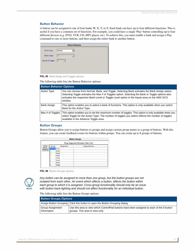
Button BehaviorA button can be assigned to one of four banks W, X, Y, or Z. Each bank can have up to four different functions. This is useful if you have a common set of functions. For example, you could have a single 'Play' button controlling up to four different devices (e.g. DVD, VCR, CD, MP3 player, etc). To achieve this, you must enable a bank and assign a Play command to one or more buttons, and then assign the entire bank to another button.
The following table lists the Button Behavior options:
Button GroupsButton Groups allow you to assign buttons to groups and assign custom group names to a group of buttons. With this feature, you can create feedback events for buttons within groups. You can create up to 8 groups of buttons.
The following table lists the Button Groups options:
FIG. 45 Bank Assign and Toggle options
Button Behavior Options
Action Type You can choose from Normal, Bank, and Toggle. Selecting Bank activates the Bank Assign option. Selecting Toggle activates the Max # of Toggles option. Selecting the Bank or Toggle options also activates the respective Bank Level or Toggle Level option in the Inputs area on the AMX DCS window.
Bank Assign This option enables you to select a bank of functions. This option is only available when you select Bank for the Action Type.
Max # of Toggles This option enables you to set the maximum number of toggles. This option is only available when you select Toggle for the Action Type. The number of toggles you select reflects the number of toggles available in the Advance Toggle area.
FIG. 46 Button Groups options
Any button can be assigned to more than one group, but the button groups are not isolated from each other. An event which affects a button, affects the button within each group to which it is assigned. Cross-group functionality should only be an issue with button back-lighting and should not affect functionality for an individual button.
Button Groups Options
Assign Button Grouping Click this button to open the Button Grouping dialog.
Group AssignmentInformation
Use this area to view which ControlPad buttons have been assigned to each of the 8 button groups. This area is view-only.
37 Novara 3000 Series ControlPads Instruction Manual
Device Configuration Software
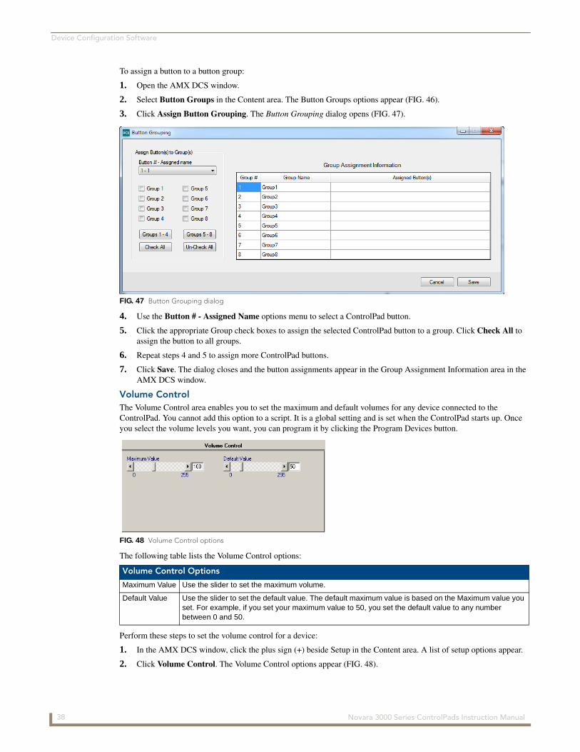
To assign a button to a button group:
1. Open the AMX DCS window.
2. Select Button Groups in the Content area. The Button Groups options appear (FIG. 46).
3. Click Assign Button Grouping. The Button Grouping dialog opens (FIG. 47).
4. Use the Button # - Assigned Name options menu to select a ControlPad button.
5. Click the appropriate Group check boxes to assign the selected ControlPad button to a group. Click Check All to assign the button to all groups.
6. Repeat steps 4 and 5 to assign more ControlPad buttons.
7. Click Save. The dialog closes and the button assignments appear in the Group Assignment Information area in the AMX DCS window.
Volume ControlThe Volume Control area enables you to set the maximum and default volumes for any device connected to the ControlPad. You cannot add this option to a script. It is a global setting and is set when the ControlPad starts up. Once you select the volume levels you want, you can program it by clicking the Program Devices button.
The following table lists the Volume Control options:
Perform these steps to set the volume control for a device:
1. In the AMX DCS window, click the plus sign (+) beside Setup in the Content area. A list of setup options appear.
2. Click Volume Control. The Volume Control options appear (FIG. 48).
FIG. 47 Button Grouping dialog
FIG. 48 Volume Control options
Volume Control Options
Maximum Value Use the slider to set the maximum volume.
Default Value Use the slider to set the default value. The default maximum value is based on the Maximum value you set. For example, if you set your maximum value to 50, you set the default value to any number between 0 and 50.
38 Novara 3000 Series ControlPads Instruction Manual

Device Configuration Software
3. Use the Maximum Value slider to set the maximum volume for the device.
4. Use the Default Value slider to set the default volume for the device.
5. In the Scripting area, click Program Devices. The volume settings are sent to the ControlPad.
InterrogationThe Interrogation option enables you to assign specific devices that are connected to the ports on the rear of the ControlPad. After assigning devices, you can view the request and status names and the hexadecimal command codes for each device. You can also view or change the Request and Status commands for RMS.
The following table lists the Interrogation options:
Perform these steps to assign a device to a ControlPad:
1. In the AMX DCS window, click the plus sign (+) beside Setup in the Content area. A list of setup options appear.
2. Click Interrogation. The Device Interrogation options appear (FIG. 49).
3. Click Select Device. The DCS Device Library dialog opens (FIG. 50).
4. Use the Make and Type menus to select the manufacturer and type of device, and click Load Devices. The dialog closes and the make is populated in the Manufacturer field of the Device Interrogation options.
If you attempt to program the volume with an empty script, the ControlPad does not reflect the change. You must program at least one line of a script for the new volume settings to take effect.
FIG. 49 Interrogation options
Interrogation Options
Manufacturer Displays the manufacturer of the device. This option is view-only on this screen. You can only change it by clicking Select Device and selecting a different Make.
Device Model Use the drop-down menu to select the model of the device for the manufacturer. No devices appear in this menu until you use the Select Device option to select a model and device type.
Clear Data Click to clear the device from the corresponding port. You must clear and reselect a device to pick up any changes to the device in the Device Library entry. Otherwise, the original RS-232 commands, responses, and formulas remain in the script, despite the library being updated.
Select Device Click to open the DCS Device Library dialog so you can select a device for the port.
Tag Data Click to open the Device Interrogation window and select which requests you want to be programmed on the ControlPad.
RMS/Settings Click to open the Assign RMS Custom Request and Status Names window which displays the Request and Status names. You can enter custom names and select the Timeout/Time for Response settings.
FIG. 50 DCS Device Library dialog
39 Novara 3000 Series ControlPads Instruction Manual
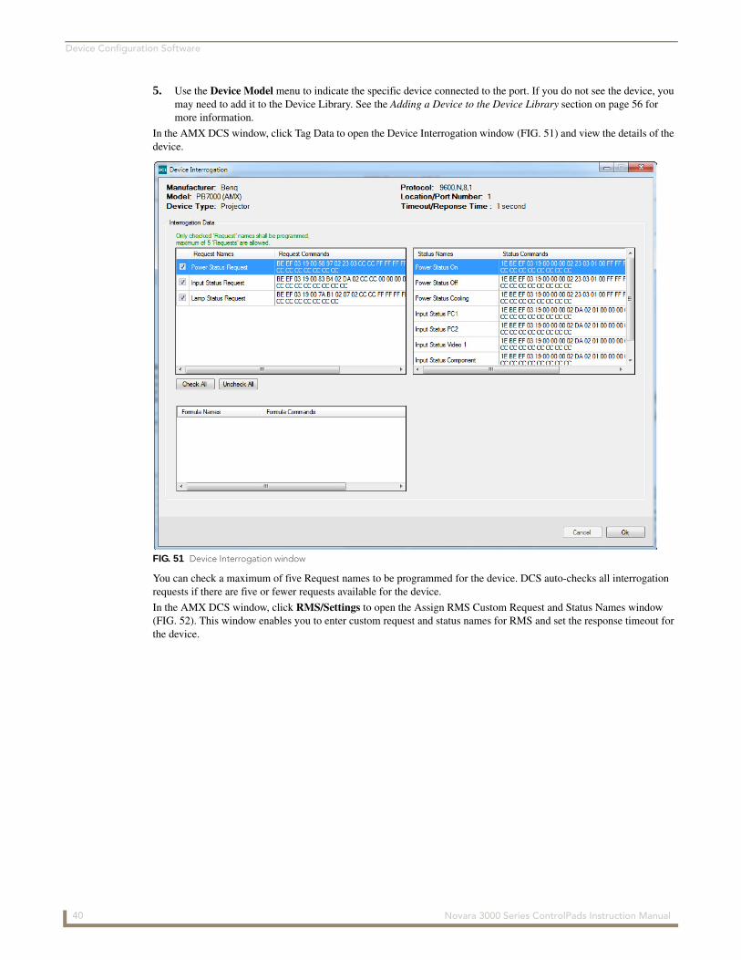
Device Configuration Software
5. Use the Device Model menu to indicate the specific device connected to the port. If you do not see the device, you may need to add it to the Device Library. See the Adding a Device to the Device Library section on page 56 for more information.
In the AMX DCS window, click Tag Data to open the Device Interrogation window (FIG. 51) and view the details of the device.
You can check a maximum of five Request names to be programmed for the device. DCS auto-checks all interrogation requests if there are five or fewer requests available for the device.
In the AMX DCS window, click RMS/Settings to open the Assign RMS Custom Request and Status Names window (FIG. 52). This window enables you to enter custom request and status names for RMS and set the response timeout for the device.
FIG. 51 Device Interrogation window
40 Novara 3000 Series ControlPads Instruction Manual
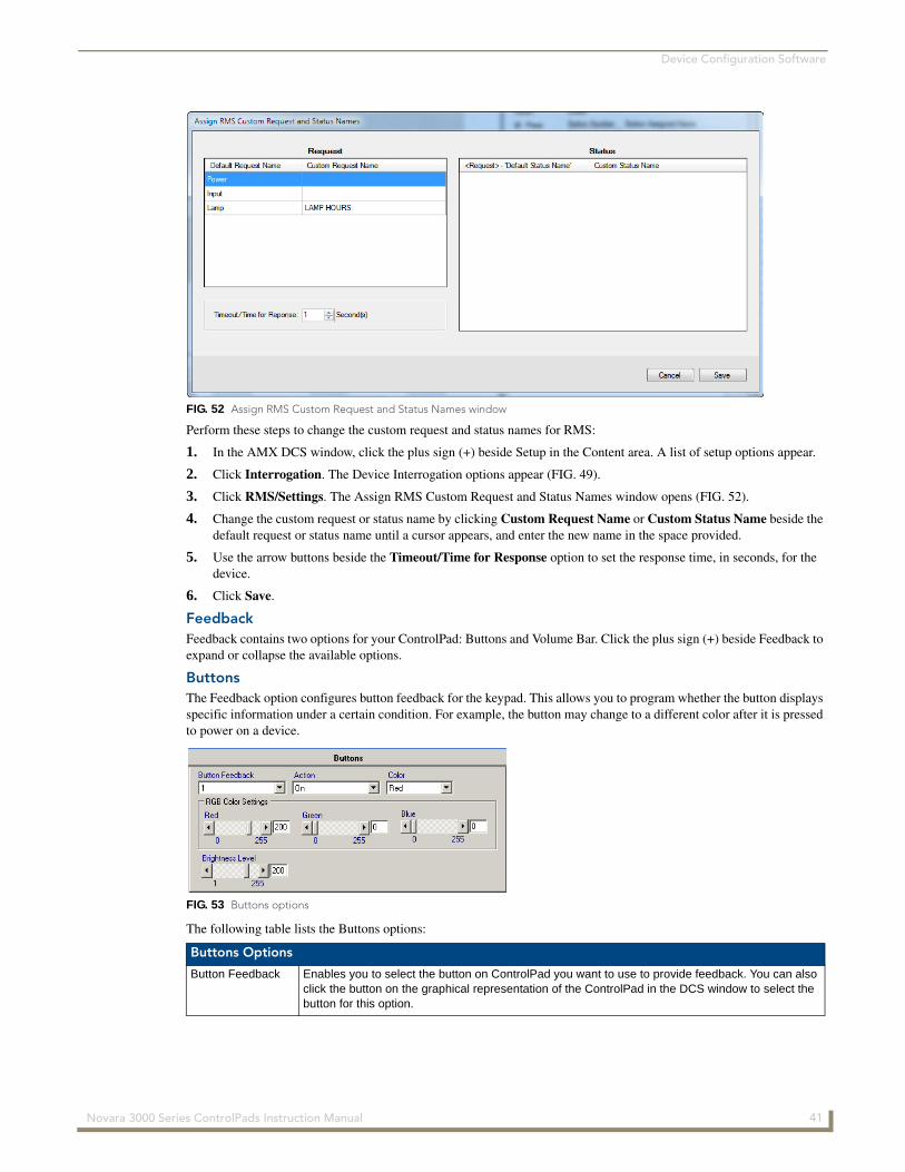
Device Configuration Software
Perform these steps to change the custom request and status names for RMS:
1. In the AMX DCS window, click the plus sign (+) beside Setup in the Content area. A list of setup options appear.
2. Click Interrogation. The Device Interrogation options appear (FIG. 49).
3. Click RMS/Settings. The Assign RMS Custom Request and Status Names window opens (FIG. 52).
4. Change the custom request or status name by clicking Custom Request Name or Custom Status Name beside the default request or status name until a cursor appears, and enter the new name in the space provided.
5. Use the arrow buttons beside the Timeout/Time for Response option to set the response time, in seconds, for the device.
6. Click Save.
FeedbackFeedback contains two options for your ControlPad: Buttons and Volume Bar. Click the plus sign (+) beside Feedback to expand or collapse the available options.
ButtonsThe Feedback option configures button feedback for the keypad. This allows you to program whether the button displays specific information under a certain condition. For example, the button may change to a different color after it is pressed to power on a device.
The following table lists the Buttons options:
FIG. 52 Assign RMS Custom Request and Status Names window
FIG. 53 Buttons options
Buttons Options
Button Feedback Enables you to select the button on ControlPad you want to use to provide feedback. You can also click the button on the graphical representation of the ControlPad in the DCS window to select the button for this option.
41 Novara 3000 Series ControlPads Instruction Manual

Device Configuration Software
Perform the following steps to set button feedback:
1. In the AMX DCS window, click the plus sign (+) beside Feedback in the Content area. A list of feedback options appear.
2. Click Buttons. The Buttons options appear (FIG. 53).
3. Select the button number from the Button Feedback options menu.
4. Use the Action options menu to indicate whether you want to turn on button feedback. Selecting Off turns off button feedback.
5. Select a color from the Color options menu, or use the RGB Color Settings sliders to indicate a different color from those listed.
6. In the Scripting area, click Add. The Feedback event now appears in the script.
Volume BarThe Volume Bar area enables you to set the brightness level for the volume indicator on the ControlPad.
The following table lists the Volume Bar options:
RS232The RS232 option configures an RS232 device for the keypad. RS232 devices connect to the RS232 serial ports on the rear of the keypad. You must use the Device Library Manager to add or import RS232 devices that you can program through DCS. Once the device you want to program is in the device library, you can load the device in the RS232 section and program events for it. See the Device Library Manager section on page 54 for more information.
Buttons Options
Action Enables you to indicate whether you want to activate button feedback. You can choose from On, Backlight, Flash, Full Off, On / All Buttons Off, On / Group Off, On / All Buttons Backlight, and On / Group Backlight. Selecting Full Off turns off button feedback and reduces LED power to zero. Selecting Group Off or Group Backlight sets the event for all buttons assigned to a button group. See the Button Groups section on page 37 for more information.
Color Enables you to indicate the color of the button feedback for the specified action.
RGB Color Settings Use the sliders to set a custom color for the button feedback.
Brightness Level Use the slider to set the brightness level of the button between 1 and 255. You can also use your pointer to select the text in the field beside the slider and manually enter the brightness level for the button.
Note: You cannot turn off the brightness level by setting the level to 0.
FIG. 54 Volume Bar options
Volume Bar Options
Action Enables you to select the volume LED action type. You can choose from On, Flash, or Power Off.
Brightness Level Use the slider to set the brightness level of the button between 1 and 255. You can also use your pointer to select the text in the field beside the slider and manually enter the brightness level for the button.
Note: You cannot turn off the brightness level by setting the level to 0.
42 Novara 3000 Series ControlPads Instruction Manual
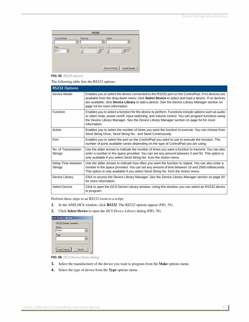
Device Configuration Software
The following table lists the RS232 options:
Perform these steps to an RS232 event to a script:
1. In the AMX DCS window, click RS232. The RS232 options appear (FIG. 55).
2. Click Select Device to open the DCS Device Library dialog (FIG. 56).
3. Select the manufacturer of the device you want to program from the Make options menu.
4. Select the type of device from the Type options menu.
FIG. 55 RS232 options
RS232 Options
Device Model Enables you to select the device connected to the RS232 port on the ControlPad. If no devices are available from the drop-down menu, click Select Device to select and load a device. If no devices are available, click Device Library to add a device. See the Device Library Manager section on page 54 for more information.
Function Enables you to select a function for the device to perform. Functions include options such as audio or video mute, power on/off, input switching, and volume control. You can program functions using the Device Library Manager. See the Device Library Manager section on page 54 for more information.
Action Enables you to select the number of times you want the function to execute. You can choose from Send String Once, Send String No., and Send Continuously.
Port Enables you to select the port on the ControlPad you want to use to execute the function. The number of ports available varies depending on the type of ControlPad you are using.
No. of Transmission Strings
Use the slider arrows to indicate the number of times you want a function to transmit. You can also enter a number in the space provided. You can set any amount between 2 and 50. This option is only available if you select Send String No. from the Action menu.
Delay Time between Strings
Use the slider arrows to indicate how often you want the function to repeat. You can also enter a number in the space provided. You can set any amount of time between 10 and 2500 milliseconds. This option is only available if you select Send String No. from the Action menu.
Device Library Click to access the Device Library Manager. See the Device Library Manager section on page 54 for more information.
Select Device Click to open the DCS Device Library window. Using this window, you can select an RS232 device to program.
FIG. 56 DCS Device Library dialog
43 Novara 3000 Series ControlPads Instruction Manual
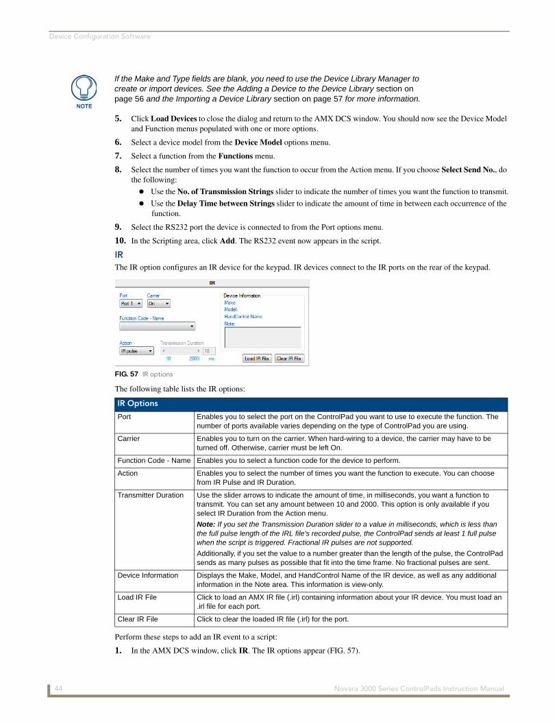
Device Configuration Software
5. Click Load Devices to close the dialog and return to the AMX DCS window. You should now see the Device Model and Function menus populated with one or more options.
6. Select a device model from the Device Model options menu.
7. Select a function from the Functions menu.
8. Select the number of times you want the function to occur from the Action menu. If you choose Select Send No., do the following:
Use the No. of Transmission Strings slider to indicate the number of times you want the function to transmit.
Use the Delay Time between Strings slider to indicate the amount of time in between each occurrence of the function.
9. Select the RS232 port the device is connected to from the Port options menu.
10. In the Scripting area, click Add. The RS232 event now appears in the script.
IRThe IR option configures an IR device for the keypad. IR devices connect to the IR ports on the rear of the keypad.
The following table lists the IR options:
Perform these steps to add an IR event to a script:
1. In the AMX DCS window, click IR. The IR options appear (FIG. 57).
If the Make and Type fields are blank, you need to use the Device Library Manager to create or import devices. See the Adding a Device to the Device Library section on page 56 and the Importing a Device Library section on page 57 for more information.
FIG. 57 IR options
IR Options
Port Enables you to select the port on the ControlPad you want to use to execute the function. The number of ports available varies depending on the type of ControlPad you are using.
Carrier Enables you to turn on the carrier. When hard-wiring to a device, the carrier may have to be turned off. Otherwise, carrier must be left On.
Function Code - Name Enables you to select a function code for the device to perform.
Action Enables you to select the number of times you want the function to execute. You can choose from IR Pulse and IR Duration.
Transmitter Duration Use the slider arrows to indicate the amount of time, in milliseconds, you want a function to transmit. You can set any amount between 10 and 2000. This option is only available if you select IR Duration from the Action menu.
Note: If you set the Transmission Duration slider to a value in milliseconds, which is less than the full pulse length of the IRL file's recorded pulse, the ControlPad sends at least 1 full pulse when the script is triggered. Fractional IR pulses are not supported.
Additionally, if you set the value to a number greater than the length of the pulse, the ControlPad sends as many pulses as possible that fit into the time frame. No fractional pulses are sent.
Device Information Displays the Make, Model, and HandControl Name of the IR device, as well as any additional information in the Note area. This information is view-only.
Load IR File Click to load an AMX IR file (.irl) containing information about your IR device. You must load an .irl file for each port.
Clear IR File Click to clear the loaded IR file (.irl) for the port.
44 Novara 3000 Series ControlPads Instruction Manual
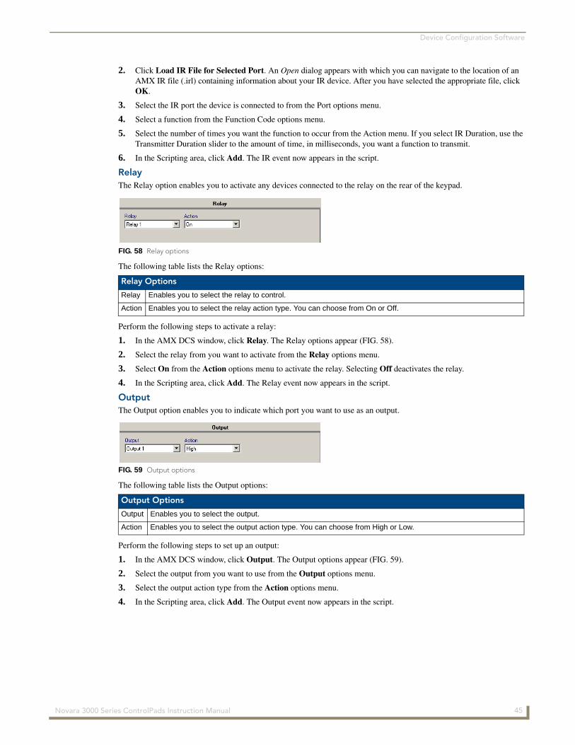
Device Configuration Software
2. Click Load IR File for Selected Port. An Open dialog appears with which you can navigate to the location of an AMX IR file (.irl) containing information about your IR device. After you have selected the appropriate file, click OK.
3. Select the IR port the device is connected to from the Port options menu.
4. Select a function from the Function Code options menu.
5. Select the number of times you want the function to occur from the Action menu. If you select IR Duration, use the Transmitter Duration slider to the amount of time, in milliseconds, you want a function to transmit.
6. In the Scripting area, click Add. The IR event now appears in the script.
RelayThe Relay option enables you to activate any devices connected to the relay on the rear of the keypad.
The following table lists the Relay options:
Perform the following steps to activate a relay:
1. In the AMX DCS window, click Relay. The Relay options appear (FIG. 58).
2. Select the relay from you want to activate from the Relay options menu.
3. Select On from the Action options menu to activate the relay. Selecting Off deactivates the relay.
4. In the Scripting area, click Add. The Relay event now appears in the script.
OutputThe Output option enables you to indicate which port you want to use as an output.
The following table lists the Output options:
Perform the following steps to set up an output:
1. In the AMX DCS window, click Output. The Output options appear (FIG. 59).
2. Select the output from you want to use from the Output options menu.
3. Select the output action type from the Action options menu.
4. In the Scripting area, click Add. The Output event now appears in the script.
FIG. 58 Relay options
Relay Options
Relay Enables you to select the relay to control.
Action Enables you to select the relay action type. You can choose from On or Off.
FIG. 59 Output options
Output Options
Output Enables you to select the output.
Action Enables you to select the output action type. You can choose from High or Low.
45 Novara 3000 Series ControlPads Instruction Manual
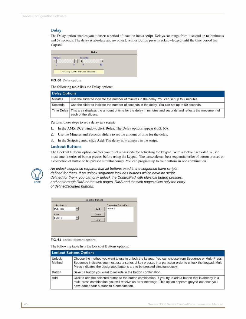
Device Configuration Software
DelayThe Delay option enables you to insert a period of inaction into a script. Delays can range from 1 second up to 9 minutes and 59 seconds. The delay is absolute and no other Event or Button press is acknowledged until the time period has elapsed.
The following table lists the Delay options:
Perform these steps to set a delay in a script:
1. In the AMX DCS window, click Delay. The Delay options appear (FIG. 60).
2. Use the Minutes and Seconds sliders to set the amount of time for the delay.
3. In the Scripting area, click Add. The delay now appears in the script.
Lockout ButtonsThe Lockout Buttons option enables you to set a passcode for activating the keypad. With a lockout activated, a user must enter a series of button presses before using the keypad. The passcode can be a sequential order of button presses or a collection of button to be pressed simultaneously. You can program up to four buttons in one combination.
The following table lists the Lockout Buttons options:
FIG. 60 Delay options
Delay Options
Minutes Use the slider to indicate the number of minutes in the delay. You can set up to 9 minutes.
Seconds Use the slider to indicate the number of seconds in the delay. You can set up to 59 seconds.
Time Delay This area displays the amount of time for the delay in minutes and seconds and reflects the movement of each of the sliders.
An unlock sequence requires that all buttons used in the sequence have scripts defined for them. If an unlock sequence includes buttons which have no script defined for them, you can only unlock the ControlPad with physical button presses, and not through RMS or the web pages. RMS and the web pages allow only the entry of defined/scripted buttons.
FIG. 61 Lockout Buttons options
Lockout Buttons Options
Unlock Method
Choose the method you want to use to unlock the keypad. You can choose from Sequence or Multi-Press. Sequence indicates you must use a series of key presses in a particular order to unlock the keypad. Multi-Press indicates the designated buttons are to be pressed simultaneously.
Button Select a button you want to include in the button combination.
Add Click to add the selected button to the button combination. If you try to add a button that is already in a multi-press combination, you will receive an error message. This option appears greyed-out once you have added four buttons to a combination.
46 Novara 3000 Series ControlPads Instruction Manual
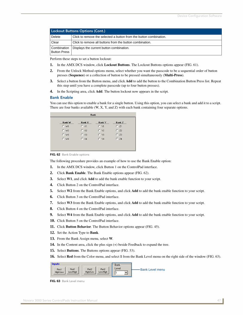
Device Configuration Software
Perform these steps to set a button lockout:
1. In the AMX DCS window, click Lockout Buttons. The Lockout Buttons options appear (FIG. 61).
2. From the Unlock Method options menu, select whether you want the passcode to be a sequential order of button presses (Sequence) or a collection of button to be pressed simultaneously (Multi-Press).
3. Select a button from the Button menu, and click Add to add the button to the Combination Button Press list. Repeat this step until you have a complete passcode (up to four button presses).
4. In the Scripting area, click Add. The button lockout now appears in the script.
Bank EnableYou can use this option to enable a bank for a single button. Using this option, you can select a bank and add it to a script. There are four banks available (W, X, Y, and Z) with each bank containing four separate options.
The following procedure provides an example of how to use the Bank Enable option:
1. In the AMX DCS window, click Button 1 on the ControlPad interface.
2. Click Bank Enable. The Bank Enable options appear (FIG. 62).
3. Select W1, and click Add to add the bank enable function to your script.
4. Click Button 2 on the ControlPad interface.
5. Select W2 from the Bank Enable options, and click Add to add the bank enable function to your script.
6. Click Button 3 on the ControlPad interface.
7. Select W3 from the Bank Enable options, and click Add to add the bank enable function to your script.
8. Click Button 4 on the ControlPad interface.
9. Select W4 from the Bank Enable options, and click Add to add the bank enable function to your script.
10. Click Button 5 on the ControlPad interface.
11. Click Button Behavior. The Button Behavior options appear (FIG. 45).
12. Set the Action Type to Bank.
13. From the Bank Assign menu, select W.
14. In the Content area, click the plus sign (+) beside Feedback to expand the tree.
15. Select Buttons. The Buttons options appear (FIG. 53).
16. Select Red from the Color menu, and select 1 from the Bank Level menu on the right side of the window (FIG. 63).
Lockout Buttons Options (Cont.)
Delete Click to remove the selected a button from the button combination.
Clear Click to remove all buttons from the button combination.
Combination Button Press
Displays the current button combination.
FIG. 62 Bank Enable options
FIG. 63 Bank Level menu
Bank Level menu
47 Novara 3000 Series ControlPads Instruction Manual

Device Configuration Software
17. Click Add to add the event to the script.
18. Select Green from the Color menu, and select 2 from the Bank Level menu on the right side of the window.
19. Click Add to add the event to the script.
20. Select Blue from the Color menu, and select 3 from the Bank Level menu on the right side of the window.
21. Click Add to add the event to the script.
22. Select Yellow from the Color menu, and select 4 from the Bank Level menu on the right side of the window.
23. Click Add to add the event to the script.
24. Click Program Devices to program the scripts on the selected ControlPads.
The ControlPad should now act in the following way:
If you press Button 1 then press Button 5, Button 5 turns red.
If you press Button 2 then press Button 5, Button 5 turns green.
If you press Button 3 then press Button 5, Button 5 turns blue.
If you press Button 4 then press Button 5, Button 5 turns yellow.
Advance ToggleThe Advance Toggle feature allows a button to skip toggles. For example, a button is configured to toggle a Device on and off, and the first press turns on the device. With a toggle programmed into the script, a second press of the same button turns off the device. If the Device is also turned off by a Time Out function, then pressing the button a 2nd time will have no effect as the Device is already off.
If you are using a delay in a script with toggles, you should include an additional toggle at the end of the script in the event that the delay caused the ControlPad to miss a toggle. Pressing a button during a delay can causes any button events to not execute during the period of delay. An advance toggle at the end of the script switches the toggle to the next event in case it was not executed.
In the AMX DCS window, click Advance Toggle. The Advance Toggle options appear (FIG. 64).
The following procedure provides an example of how to use the Advance Toggle option.
1. In the AMX DCS window, click Button 1 on the ControlPad interface.
2. Select Button Behavior in the Content area, and ensure that the Action Type is set to Normal.
3. In the Content area, click the plus sign (+) beside Feedback to expand the tree.
4. Select Buttons. The Buttons options appear (FIG. 53).
5. Select Red from the Color menu, and Add to add the event to the script.
6. Click Button 2 on the ControlPad interface.
7. Select Button Behavior in the Content area, and set the Action Type is set to Toggle.
8. Set the Max # of Toggles option to 2.
9. Select Buttons in the Content area.
You may find that executing a button press through RMS does not advance toggle. If this occurs in RMS, create a virtual button that contains all the events you want to run, and if you want to change the toggle level, use the advance toggle level to X script function.
FIG. 64 Advance Toggle options
48 Novara 3000 Series ControlPads Instruction Manual
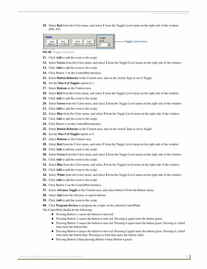
Device Configuration Software
10. Select Red from the Color menu, and select 1 from the Toggle Level menu on the right side of the window (FIG. 65).
11. Click Add to add the event to the script.
12. Select Green from the Color menu, and select 2 from the Toggle Level menu on the right side of the window.
13. Click Add to add the event to the script.
14. Click Button 3 on the ControlPad interface.
15. Select Button Behavior in the Content area, and set the Action Type is set to Toggle.
16. Set the Max # of Toggles option to 3.
17. Select Buttons in the Content area.
18. Select Red from the Color menu, and select 1 from the Toggle Level menu on the right side of the window.
19. Click Add to add the event to the script.
20. Select Green from the Color menu, and select 2 from the Toggle Level menu on the right side of the window.
21. Click Add to add the event to the script.
22. Select Blue from the Color menu, and select 3 from the Toggle Level menu on the right side of the window.
23. Click Add to add the event to the script.
24. Click Button 4 on the ControlPad interface.
25. Select Button Behavior in the Content area, and set the Action Type is set to Toggle.
26. Set the Max # of Toggles option to 4.
27. Select Buttons in the Content area.
28. Select Red from the Color menu, and select 1 from the Toggle Level menu on the right side of the window.
29. Click Add to add the event to the script.
30. Select Green from the Color menu, and select 2 from the Toggle Level menu on the right side of the window.
31. Click Add to add the event to the script.
32. Select Blue from the Color menu, and select 3 from the Toggle Level menu on the right side of the window.
33. Click Add to add the event to the script.
34. Select White from the Color menu, and select 4 from the Toggle Level menu on the right side of the window.
35. Click Add to add the event to the script.
36. Click Button 5 on the ControlPad interface.
37. Select Advance Toggle in the Content area, and select button 4 from the Button menu.
38. Select 2nd from the Advance to option buttons.
39. Click Add to add the event to the script.
40. Click Program Devices to program the scripts on the selected ControlPads.
The ControlPad should do the following:
Pressing Button 1 causes the button to turn red.
Pressing Button 2 causes the button to turn red. Pressing it again turns the button green.
Pressing Button 3 causes the button to turn red. Pressing it again turns the button green. Pressing it a third time turns the button blue.
Pressing Button 4 causes the button to turn red. Pressing it again turns the button green. Pressing it a third time turns the button blue. Pressing it a final time turns the button white.
Pressing Button 5 then pressing Button 4 turns Button 4 green.
FIG. 65 Toggle Level menu
Toggle Level menu
49 Novara 3000 Series ControlPads Instruction Manual
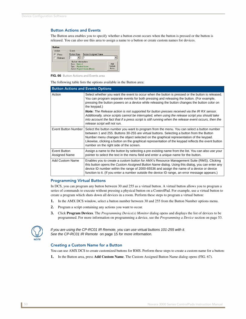
Device Configuration Software
Button Actions and EventsThe Button area enables you to specify whether a button event occurs when the button is pressed or the button is released. You can also use this area to assign a name to a button or create custom names for devices.
The following table lists the options available in the Button area:
Programming Virtual ButtonsIn DCS, you can program any button between 30 and 255 as a virtual button. A virtual button allows you to program a series of commands to execute without pressing a physical button on a ControlPad. For example, use a virtual button to create a program which shuts down all devices in a room. Perform these steps to program a virtual button:
1. In the AMX DCS window, select a button number between 30 and 255 from the Button Number options menu.
2. Program a script containing any actions you want to occur.
3. Click Program Devices. The Programming Device(s) Monitor dialog opens and displays the list of devices to be programmed. For more information on programming a device, see the Programming a Device section on page 53.
Creating a Custom Name for a ButtonYou can use AMX DCS to create customized buttons for RMS. Perform these steps to create a custom name for a button:
1. In the Button area, press Add Custom Name. The Custom Assigned Button Name dialog opens (FIG. 67).
FIG. 66 Button Actions and Events area
Button Actions and Events Options
Action Select whether you want the event to occur when the button is pressed or the button is released. You can program separate events for both pressing and releasing the button. (For example, pressing the button powers on a device while releasing the button changes the button color on the keypad.)
Note: The Release action is not supported for button presses received via the IR RX sensor. Additionally, since scripts cannot be interrupted, when using the release script you should take into account the fact that if a press script is still running when the release event occurs, then the release script will not run.
Event Button Number Select the button number you want to program from the menu. You can select a button number between 1 and 255. Buttons 30-255 are virtual buttons. Selecting a button from the Button Number menu changes the object selected on the graphical representation of the keypad. Likewise, clicking a button on the graphical representation of the keypad reflects the event button number on the right side of the screen.
Event Button Assigned Name
Assign a name to the button by selecting a pre-existing name from the list. You can also use your pointer to select the text in the menu field and enter a unique name for the button.
Add Custom Name Enables you to create a custom button for AMX’s Resource Management Suite (RMS). Clicking this button opens the Custom Assigned Button Name dialog. Using this dialog, you can enter any device ID number within the range of 2000-65536 and assign the name of a device or device function to it. (If you enter a number outside the device ID range, an error message appears.)
If you are using the CP-RC01 IR Remote, you can use virtual buttons 101-255 with it. See the CP-RC01 IR Remote on page 15 for more information.
50 Novara 3000 Series ControlPads Instruction Manual
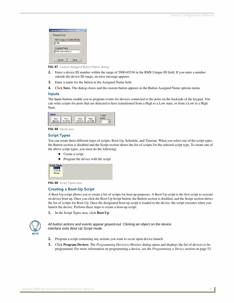
Device Configuration Software
2. Enter a device ID number within the range of 2000-65536 in the RMS Unique ID field. If you enter a number outside the device ID range, an error message appears.
3. Enter a name for the button in the Assigned Name field.
4. Click Save. The dialog closes and the custom button appears in the Button Assigned Name options menu.
InputsThe Input buttons enable you to program events for devices connected to the ports on the backside of the keypad. You can write scripts for ports that are detected to have transitioned from a High to a Low state, or from a Low to a High State.
Script TypesYou can create three different types of scripts: Boot-Up, Schedule, and Timeout. When you select one of the script types, the Button section is disabled and the Script section shows the list of scripts for the selected script type. To create one of the above script types, you must do the following:
Create a script
Program the device with the script
Creating a Boot-Up ScriptA Boot-Up script allows you to create a list of scripts for boot up purposes. A Boot-Up script is the first script to execute on device boot up. Once you click the Boot-Up Script button, the Button section is disabled, and the Script section shows the list of scripts for Boot Up. Once the designated boot-up script is loaded to the device, the script executes when you launch the device. Perform these steps to create a boot-up script:
1. In the Script Types area, click Boot Up.
2. Program a script containing any actions you want to occur upon device launch.
3. Click Program Devices. The Programming Device(s) Monitor dialog opens and displays the list of devices to be programmed. For more information on programming a device, see the Programming a Device section on page 53.
FIG. 67 Custom Assigned Button Name dialog
FIG. 68 Inputs area
FIG. 69 Script Types area
All button actions and events appear greyed-out. Clicking an object on the device interface exits Boot Up Script mode.
51 Novara 3000 Series ControlPads Instruction Manual
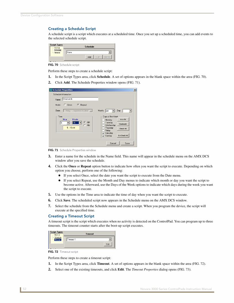
Device Configuration Software
Creating a Schedule ScriptA schedule script is a script which executes at a scheduled time. Once you set up a scheduled time, you can add events to the selected schedule script.
Perform these steps to create a schedule script:
1. In the Script Types area, click Schedule. A set of options appears in the blank space within the area (FIG. 70).
2. Click Add. The Schedule Properties window opens (FIG. 71).
3. Enter a name for the schedule in the Name field. This name will appear in the schedule menu on the AMX DCS window after you save the schedule.
4. Click the Once or Repeat option button to indicate how often you want the script to execute. Depending on which option you choose, perform one of the following:
If you select Once, select the date you want the script to execute from the Date menu.
If you select Repeat, use the Month and Day menus to indicate which month or day you want the script to become active. Afterward, use the Days of the Week options to indicate which days during the week you want the script to execute.
5. Use the options in the Time area to indicate the time of day when you want the script to execute.
6. Click Save. The scheduled script now appears in the Schedule menu on the AMX DCS window.
7. Select the schedule from the Schedule menu and create a script. When you program the device, the script will execute at the specified time.
Creating a Timeout ScriptA timeout script is the script which executes when no activity is detected on the ControlPad. You can program up to three timeouts. The timeout counter starts after the boot-up script executes.
Perform these steps to create a timeout script:
1. In the Script Types area, click Timeout. A set of options appears in the blank space within the area (FIG. 72).
2. Select one of the existing timeouts, and click Edit. The Timeout Properties dialog opens (FIG. 73).
FIG. 70 Schedule script
FIG. 71 Schedule Properties window
FIG. 72 Timeout script
52 Novara 3000 Series ControlPads Instruction Manual
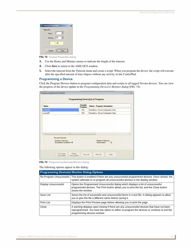
Device Configuration Software
3. Use the Hours and Minutes menus to indicate the length of the timeout.
4. Click Save to return to the AMX DCS window.
5. Select the timeout from the Timeout menu and create a script. When you program the device, the script will execute after the specified amount of time elapses without any activity on the ControlPad.
Programming a DeviceClick the Program Devices button to program configuration data and scripts to all tagged Novara devices. You can view the progress of the device update in the Programming Device(s) Monitor dialog (FIG. 74).
The following options appear in this dialog:
FIG. 73 Timeout Properties dialog
FIG. 74 Programming Device(s) Monitor dialog
Programming Device(s) Monitor Dialog Options
Re-Program Unsuccessful This button is enabled if there are any unsuccessful programmed devices. Once clicked, the system attempts to re-program all unsuccessful devices in the display window.
Display Unsuccessful Opens the Programmed Unsuccessful dialog which displays a list of unsuccessful programmed devices. The Print button allows you to print the list, and the Close button closes the window.
Save List Saves the list of successful and unsuccessful items in a text file. A dialog appears to allow you to give the file a different name before saving it.
Print List Displays the Print Preview page before allowing you to print the page.
Close A warning displays upon closing if there are any unsuccessful devices that have not been reprogrammed. You have the option to either re-program the devices or continue to exit the programming devices window
53 Novara 3000 Series ControlPads Instruction Manual
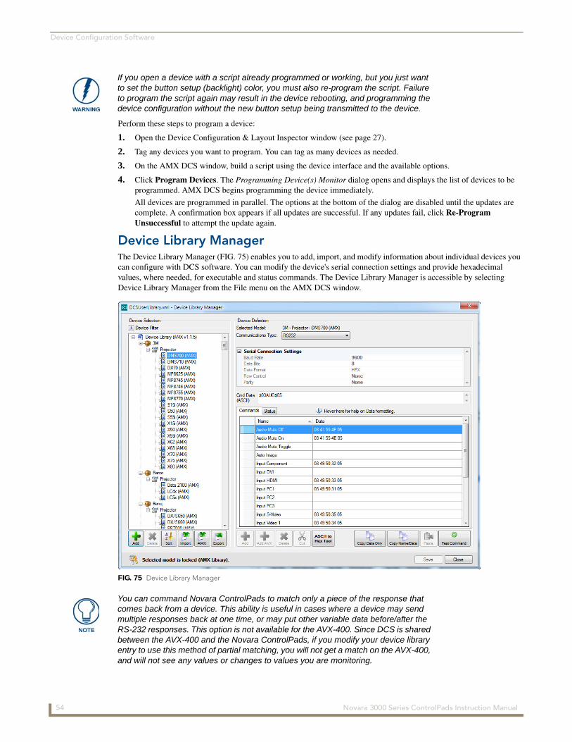
Device Configuration Software
Perform these steps to program a device:
1. Open the Device Configuration & Layout Inspector window (see page 27).
2. Tag any devices you want to program. You can tag as many devices as needed.
3. On the AMX DCS window, build a script using the device interface and the available options.
4. Click Program Devices. The Programming Device(s) Monitor dialog opens and displays the list of devices to be programmed. AMX DCS begins programming the device immediately.
All devices are programmed in parallel. The options at the bottom of the dialog are disabled until the updates are complete. A confirmation box appears if all updates are successful. If any updates fail, click Re-Program Unsuccessful to attempt the update again.
Device Library ManagerThe Device Library Manager (FIG. 75) enables you to add, import, and modify information about individual devices you can configure with DCS software. You can modify the device's serial connection settings and provide hexadecimal values, where needed, for executable and status commands. The Device Library Manager is accessible by selecting Device Library Manager from the File menu on the AMX DCS window.
If you open a device with a script already programmed or working, but you just want to set the button setup (backlight) color, you must also re-program the script. Failure to program the script again may result in the device rebooting, and programming the device configuration without the new button setup being transmitted to the device.
FIG. 75 Device Library Manager
You can command Novara ControlPads to match only a piece of the response that comes back from a device. This ability is useful in cases where a device may send multiple responses back at one time, or may put other variable data before/after the RS-232 responses. This option is not available for the AVX-400. Since DCS is shared between the AVX-400 and the Novara ControlPads, if you modify your device library entry to use this method of partial matching, you will not get a match on the AVX-400, and will not see any values or changes to values you are monitoring.
54 Novara 3000 Series ControlPads Instruction Manual
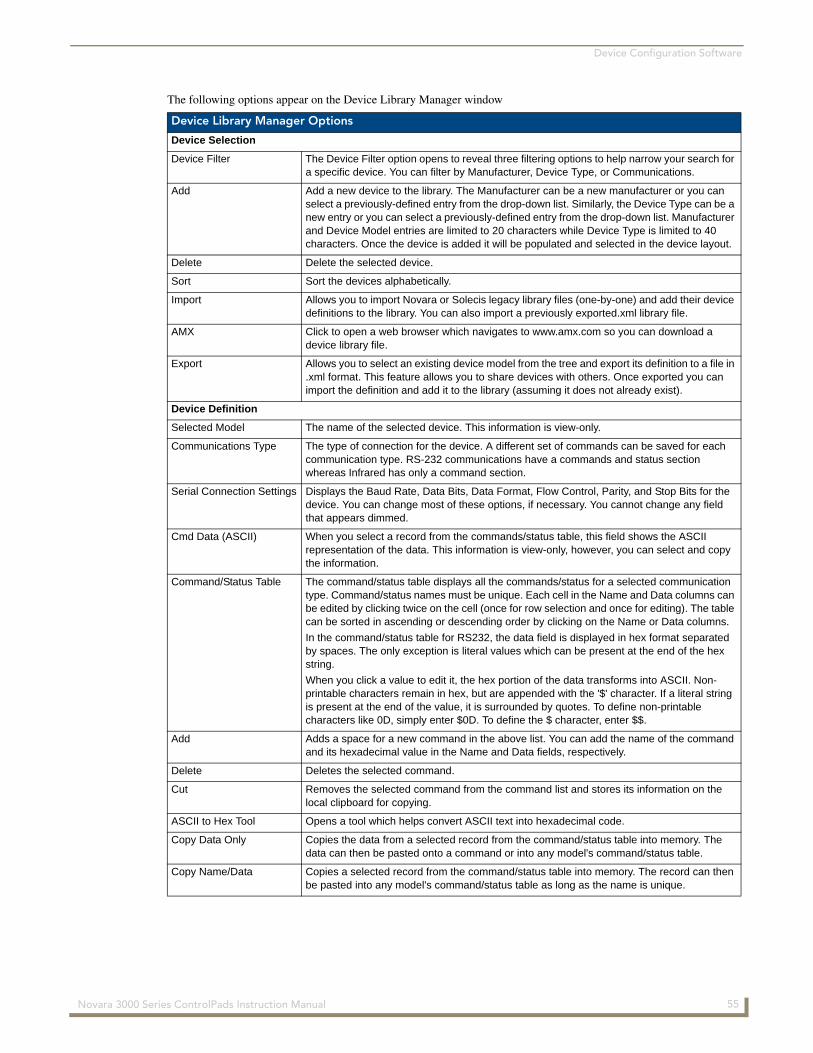
Device Configuration Software
The following options appear on the Device Library Manager window
Device Library Manager Options
Device Selection
Device Filter The Device Filter option opens to reveal three filtering options to help narrow your search for a specific device. You can filter by Manufacturer, Device Type, or Communications.
Add Add a new device to the library. The Manufacturer can be a new manufacturer or you can select a previously-defined entry from the drop-down list. Similarly, the Device Type can be a new entry or you can select a previously-defined entry from the drop-down list. Manufacturer and Device Model entries are limited to 20 characters while Device Type is limited to 40 characters. Once the device is added it will be populated and selected in the device layout.
Delete Delete the selected device.
Sort Sort the devices alphabetically.
Import Allows you to import Novara or Solecis legacy library files (one-by-one) and add their device definitions to the library. You can also import a previously exported.xml library file.
AMX Click to open a web browser which navigates to www.amx.com so you can download a device library file.
Export Allows you to select an existing device model from the tree and export its definition to a file in .xml format. This feature allows you to share devices with others. Once exported you can import the definition and add it to the library (assuming it does not already exist).
Device Definition
Selected Model The name of the selected device. This information is view-only.
Communications Type The type of connection for the device. A different set of commands can be saved for each communication type. RS-232 communications have a commands and status section whereas Infrared has only a command section.
Serial Connection Settings Displays the Baud Rate, Data Bits, Data Format, Flow Control, Parity, and Stop Bits for the device. You can change most of these options, if necessary. You cannot change any field that appears dimmed.
Cmd Data (ASCII) When you select a record from the commands/status table, this field shows the ASCII representation of the data. This information is view-only, however, you can select and copy the information.
Command/Status Table The command/status table displays all the commands/status for a selected communication type. Command/status names must be unique. Each cell in the Name and Data columns can be edited by clicking twice on the cell (once for row selection and once for editing). The table can be sorted in ascending or descending order by clicking on the Name or Data columns.
In the command/status table for RS232, the data field is displayed in hex format separated by spaces. The only exception is literal values which can be present at the end of the hex string.
When you click a value to edit it, the hex portion of the data transforms into ASCII. Non-printable characters remain in hex, but are appended with the '$' character. If a literal string is present at the end of the value, it is surrounded by quotes. To define non-printable characters like 0D, simply enter $0D. To define the $ character, enter $$.
Add Adds a space for a new command in the above list. You can add the name of the command and its hexadecimal value in the Name and Data fields, respectively.
Delete Deletes the selected command.
Cut Removes the selected command from the command list and stores its information on the local clipboard for copying.
ASCII to Hex Tool Opens a tool which helps convert ASCII text into hexadecimal code.
Copy Data Only Copies the data from a selected record from the command/status table into memory. The data can then be pasted onto a command or into any model's command/status table.
Copy Name/Data Copies a selected record from the command/status table into memory. The record can then be pasted into any model's command/status table as long as the name is unique.
55 Novara 3000 Series ControlPads Instruction Manual
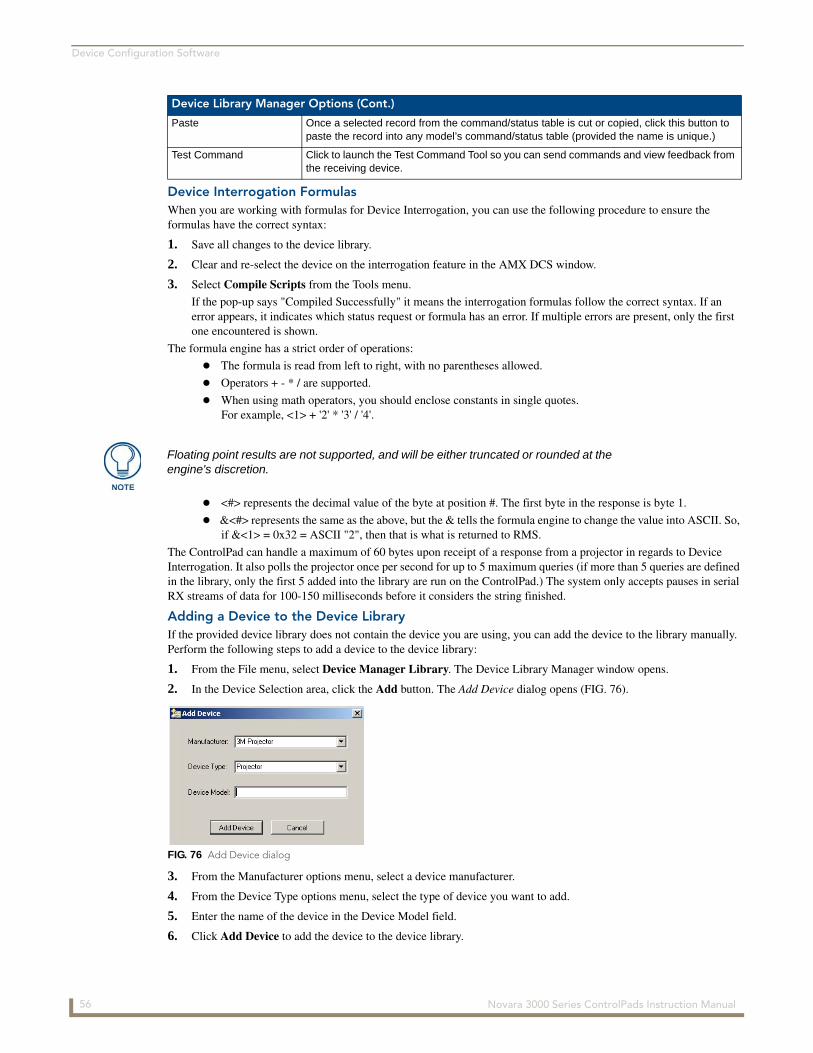
Device Configuration Software
Device Interrogation FormulasWhen you are working with formulas for Device Interrogation, you can use the following procedure to ensure the formulas have the correct syntax:
1. Save all changes to the device library.
2. Clear and re-select the device on the interrogation feature in the AMX DCS window.
3. Select Compile Scripts from the Tools menu.
If the pop-up says "Compiled Successfully" it means the interrogation formulas follow the correct syntax. If an error appears, it indicates which status request or formula has an error. If multiple errors are present, only the first one encountered is shown.
The formula engine has a strict order of operations:
The formula is read from left to right, with no parentheses allowed.
Operators + - * / are supported.
When using math operators, you should enclose constants in single quotes. For example, <1> + '2' * '3' / '4'.
<#> represents the decimal value of the byte at position #. The first byte in the response is byte 1.
&<#> represents the same as the above, but the & tells the formula engine to change the value into ASCII. So, if &<1> = 0x32 = ASCII "2", then that is what is returned to RMS.
The ControlPad can handle a maximum of 60 bytes upon receipt of a response from a projector in regards to Device Interrogation. It also polls the projector once per second for up to 5 maximum queries (if more than 5 queries are defined in the library, only the first 5 added into the library are run on the ControlPad.) The system only accepts pauses in serial RX streams of data for 100-150 milliseconds before it considers the string finished.
Adding a Device to the Device LibraryIf the provided device library does not contain the device you are using, you can add the device to the library manually. Perform the following steps to add a device to the device library:
1. From the File menu, select Device Manager Library. The Device Library Manager window opens.
2. In the Device Selection area, click the Add button. The Add Device dialog opens (FIG. 76).
3. From the Manufacturer options menu, select a device manufacturer.
4. From the Device Type options menu, select the type of device you want to add.
5. Enter the name of the device in the Device Model field.
6. Click Add Device to add the device to the device library.
Device Library Manager Options (Cont.)
Paste Once a selected record from the command/status table is cut or copied, click this button to paste the record into any model’s command/status table (provided the name is unique.)
Test Command Click to launch the Test Command Tool so you can send commands and view feedback from the receiving device.
Floating point results are not supported, and will be either truncated or rounded at the engine's discretion.
FIG. 76 Add Device dialog
56 Novara 3000 Series ControlPads Instruction Manual
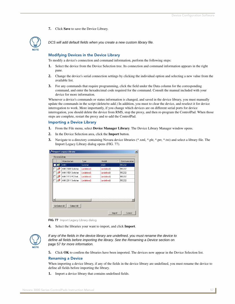
Device Configuration Software
7. Click Save to save the Device Library.
Modifying Devices in the Device LibraryTo modify a device's connection and command information, perform the following steps:
1. Select the device from the Device Selection tree. Its connection and command information appears in the right pane.
2. Change the device's serial connection settings by clicking the individual option and selecting a new value from the available list.
3. For any commands that require programming, click the field under the Data column for the corresponding command, and enter the hexadecimal code required for the command. Consult the manual included with your device for more information.
Whenever a device's commands or status information is changed, and saved in the device library, you must manually update the commands in the script (delete/re-add.) In addition, you must to clear the device, and reselect it for device interrogation to work. More importantly, if you change which devices are on different serial ports for device interrogation, you should delete the device from RMS, stop the proxy, and then re-program the ControlPad. When those steps are complete, restart the proxy and re-add the ControlPad.
Importing a Device Library
1. From the File menu, select Device Manager Library. The Device Library Manager window opens.
2. In the Device Selection area, click the Import button.
3. Navigate to a directory containing Novara device libraries (*.xml, *.plr, *.prr, *.txt) and select a library file. The Import Legacy Library dialog opens (FIG. 77).
4. Select the libraries your want to import, and click Import.
5. Click OK to confirm the libraries have been imported. The devices now appear in the Device Selection list.
Renaming a DeviceWhen importing a device library, if any of the fields in the device library are undefined, you must rename the device to define all fields before importing the library.
1. Import a device library that contains undefined fields.
DCS will add default fields when you create a new custom library file.
FIG. 77 Import Legacy Library dialog
If any of the fields in the device library are undefined, you must rename the device to define all fields before importing the library. See the Renaming a Device section on page 57 for more information.
57 Novara 3000 Series ControlPads Instruction Manual
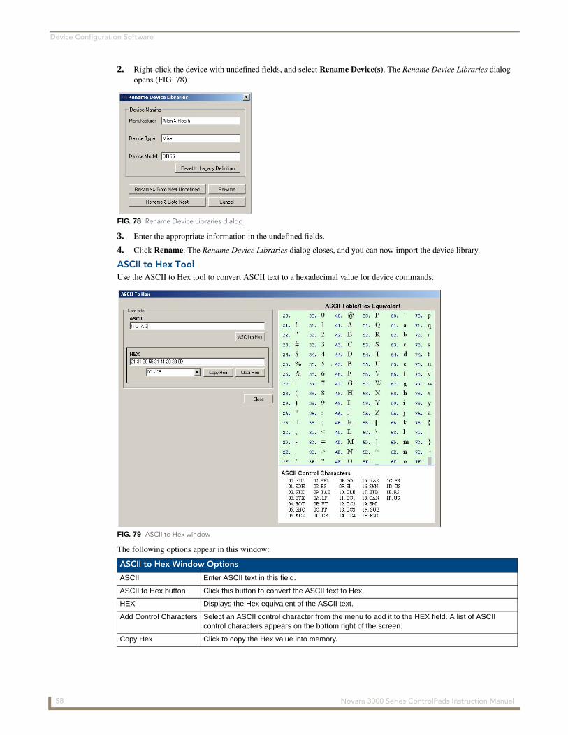
Device Configuration Software
2. Right-click the device with undefined fields, and select Rename Device(s). The Rename Device Libraries dialog opens (FIG. 78).
3. Enter the appropriate information in the undefined fields.
4. Click Rename. The Rename Device Libraries dialog closes, and you can now import the device library.
ASCII to Hex ToolUse the ASCII to Hex tool to convert ASCII text to a hexadecimal value for device commands.
The following options appear in this window:
FIG. 78 Rename Device Libraries dialog
FIG. 79 ASCII to Hex window
ASCII to Hex Window Options
ASCII Enter ASCII text in this field.
ASCII to Hex button Click this button to convert the ASCII text to Hex.
HEX Displays the Hex equivalent of the ASCII text.
Add Control Characters Select an ASCII control character from the menu to add it to the HEX field. A list of ASCII control characters appears on the bottom right of the screen.
Copy Hex Click to copy the Hex value into memory.
58 Novara 3000 Series ControlPads Instruction Manual
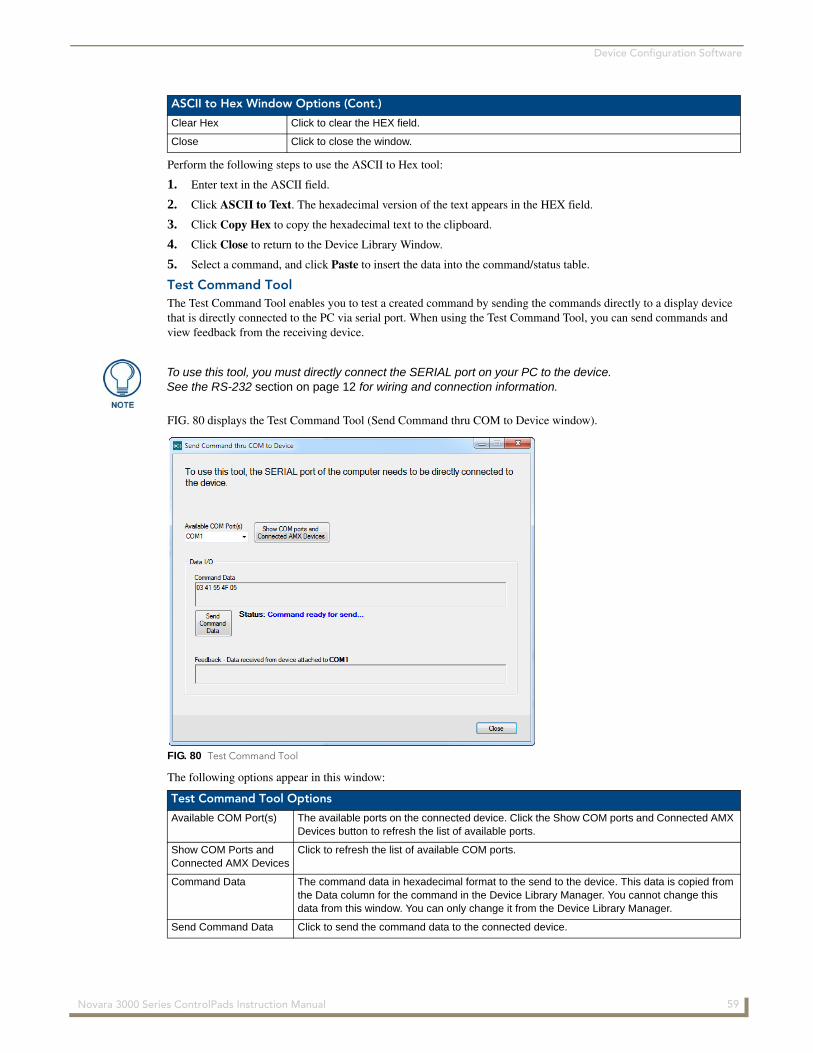
Device Configuration Software
Perform the following steps to use the ASCII to Hex tool:
1. Enter text in the ASCII field.
2. Click ASCII to Text. The hexadecimal version of the text appears in the HEX field.
3. Click Copy Hex to copy the hexadecimal text to the clipboard.
4. Click Close to return to the Device Library Window.
5. Select a command, and click Paste to insert the data into the command/status table.
Test Command ToolThe Test Command Tool enables you to test a created command by sending the commands directly to a display device that is directly connected to the PC via serial port. When using the Test Command Tool, you can send commands and view feedback from the receiving device.
FIG. 80 displays the Test Command Tool (Send Command thru COM to Device window).
The following options appear in this window:
ASCII to Hex Window Options (Cont.)
Clear Hex Click to clear the HEX field.
Close Click to close the window.
To use this tool, you must directly connect the SERIAL port on your PC to the device. See the RS-232 section on page 12 for wiring and connection information.
FIG. 80 Test Command Tool
Test Command Tool Options
Available COM Port(s) The available ports on the connected device. Click the Show COM ports and Connected AMX Devices button to refresh the list of available ports.
Show COM Ports andConnected AMX Devices
Click to refresh the list of available COM ports.
Command Data The command data in hexadecimal format to the send to the device. This data is copied from the Data column for the command in the Device Library Manager. You cannot change this data from this window. You can only change it from the Device Library Manager.
Send Command Data Click to send the command data to the connected device.
59 Novara 3000 Series ControlPads Instruction Manual
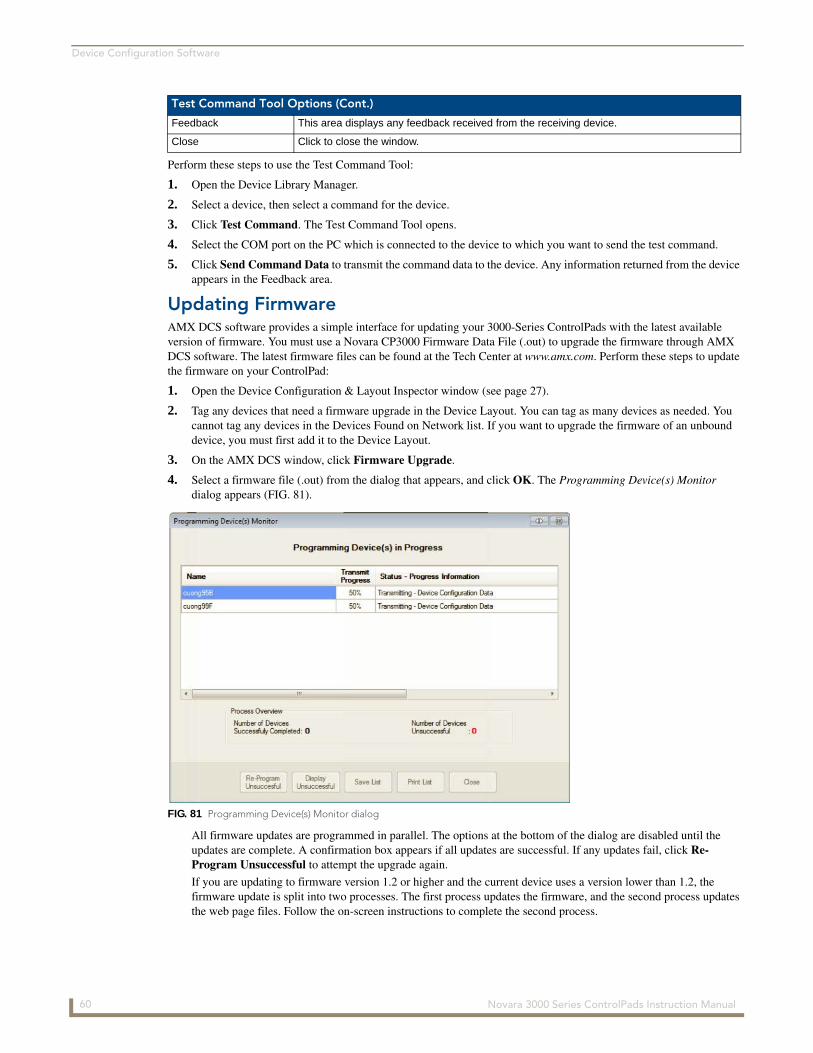
Device Configuration Software
Perform these steps to use the Test Command Tool:
1. Open the Device Library Manager.
2. Select a device, then select a command for the device.
3. Click Test Command. The Test Command Tool opens.
4. Select the COM port on the PC which is connected to the device to which you want to send the test command.
5. Click Send Command Data to transmit the command data to the device. Any information returned from the device appears in the Feedback area.
Updating FirmwareAMX DCS software provides a simple interface for updating your 3000-Series ControlPads with the latest available version of firmware. You must use a Novara CP3000 Firmware Data File (.out) to upgrade the firmware through AMX DCS software. The latest firmware files can be found at the Tech Center at www.amx.com. Perform these steps to update the firmware on your ControlPad:
1. Open the Device Configuration & Layout Inspector window (see page 27).
2. Tag any devices that need a firmware upgrade in the Device Layout. You can tag as many devices as needed. You cannot tag any devices in the Devices Found on Network list. If you want to upgrade the firmware of an unbound device, you must first add it to the Device Layout.
3. On the AMX DCS window, click Firmware Upgrade.
4. Select a firmware file (.out) from the dialog that appears, and click OK. The Programming Device(s) Monitor dialog appears (FIG. 81).
All firmware updates are programmed in parallel. The options at the bottom of the dialog are disabled until the updates are complete. A confirmation box appears if all updates are successful. If any updates fail, click Re-Program Unsuccessful to attempt the upgrade again.
If you are updating to firmware version 1.2 or higher and the current device uses a version lower than 1.2, the firmware update is split into two processes. The first process updates the firmware, and the second process updates the web page files. Follow the on-screen instructions to complete the second process.
Test Command Tool Options (Cont.)
Feedback This area displays any feedback received from the receiving device.
Close Click to close the window.
FIG. 81 Programming Device(s) Monitor dialog
60 Novara 3000 Series ControlPads Instruction Manual

Device Configuration Software
When you upgrade a ControlPad from a 1.0 version of firmware to a 1.2 version of firmware, the firmware must be upgraded two times. DCS normally prompts you to perform both upgrades. If you do not run the upgrade two times, the Web Console will not be available. Additionally, whenever a 1.2 version of firmware is upgraded, you MUST wait 2 minutes before attempting to program the ControlPad. This is true even if DCS says the firmware update is complete. The ControlPad sends the "complete" message to DCS before it has actually unpacked the web pages, and the board will be online (and could be programmed) while this unpacking is ongoing. You should not program, or press buttons physically, via the web, or via RMS during this time.
During a firmware upgrade, the ControlPad runs sluggishly, and may skip scripted events and/or appear offline to RMS. You should only perform a firmware upgrade when the ControlPad is not in use, and no scheduled events or macros are set to run from RMS enabled ControlPads.
If you need to downgrade the firmware from a 1.2.xx version to a 1.0.xx version, you must remove any scripting pertaining to options only available in version 1.2.xx and above. Your scripts cannot contain interrogation data or any configuration data including Bank, Toggle, Disable Schedule, or Volume LED from a 1.2.xx code release. Running scripts with these features on 1.0.xx firmware may cause errors with your ControlPad which can only be resolved by pressing the Reset button on the ControlPad and rebooting the system.
If you are using Windows 7 Home Premium, 32-bit, US English version, you may experience an incomplete firmware upgrade. If this occurs, you can perform a complete firmware upgrade by disabling your firewall. You can re-enable the firewall after the firmware upgrade is complete.
61 Novara 3000 Series ControlPads Instruction Manual

Device Configuration Software
62 Novara 3000 Series ControlPads Instruction Manual
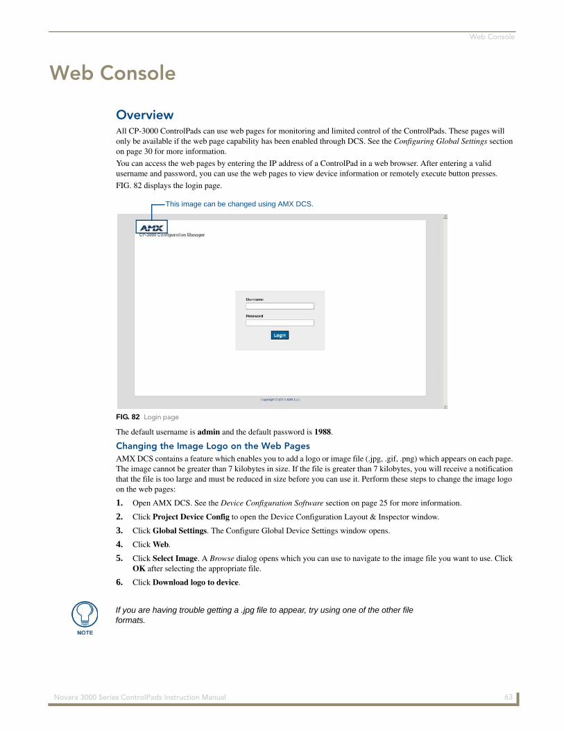
Web Console
Web Console
OverviewAll CP-3000 ControlPads can use web pages for monitoring and limited control of the ControlPads. These pages will only be available if the web page capability has been enabled through DCS. See the Configuring Global Settings section on page 30 for more information.
You can access the web pages by entering the IP address of a ControlPad in a web browser. After entering a valid username and password, you can use the web pages to view device information or remotely execute button presses.
FIG. 82 displays the login page.
The default username is admin and the default password is 1988.
Changing the Image Logo on the Web PagesAMX DCS contains a feature which enables you to add a logo or image file (.jpg, .gif, .png) which appears on each page. The image cannot be greater than 7 kilobytes in size. If the file is greater than 7 kilobytes, you will receive a notification that the file is too large and must be reduced in size before you can use it. Perform these steps to change the image logo on the web pages:
1. Open AMX DCS. See the Device Configuration Software section on page 25 for more information.
2. Click Project Device Config to open the Device Configuration Layout & Inspector window.
3. Click Global Settings. The Configure Global Device Settings window opens.
4. Click Web.
5. Click Select Image. A Browse dialog opens which you can use to navigate to the image file you want to use. Click OK after selecting the appropriate file.
6. Click Download logo to device.
FIG. 82 Login page
This image can be changed using AMX DCS.
If you are having trouble getting a .jpg file to appear, try using one of the other file formats.
63 Novara 3000 Series ControlPads Instruction Manual
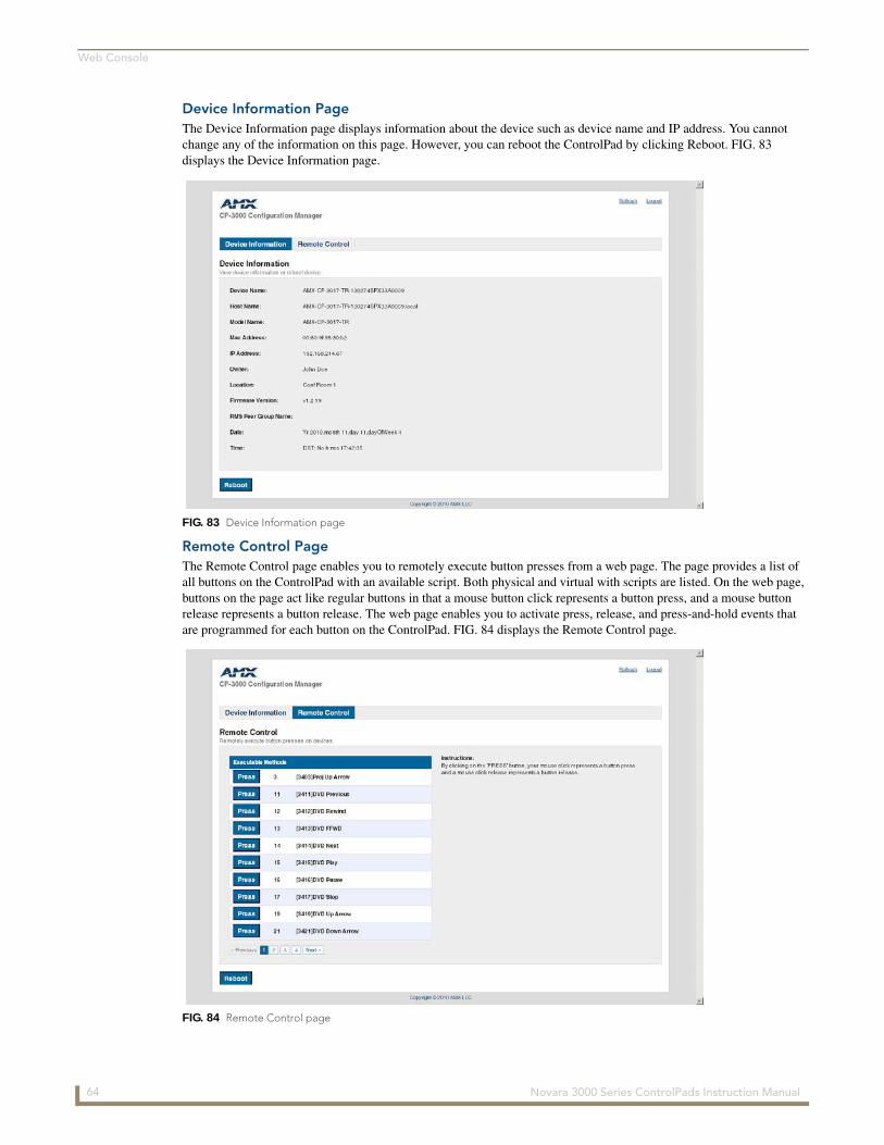
Web Console
Device Information PageThe Device Information page displays information about the device such as device name and IP address. You cannot change any of the information on this page. However, you can reboot the ControlPad by clicking Reboot. FIG. 83 displays the Device Information page.
Remote Control PageThe Remote Control page enables you to remotely execute button presses from a web page. The page provides a list of all buttons on the ControlPad with an available script. Both physical and virtual with scripts are listed. On the web page, buttons on the page act like regular buttons in that a mouse button click represents a button press, and a mouse button release represents a button release. The web page enables you to activate press, release, and press-and-hold events that are programmed for each button on the ControlPad. FIG. 84 displays the Remote Control page.
FIG. 83 Device Information page
FIG. 84 Remote Control page
64 Novara 3000 Series ControlPads Instruction Manual
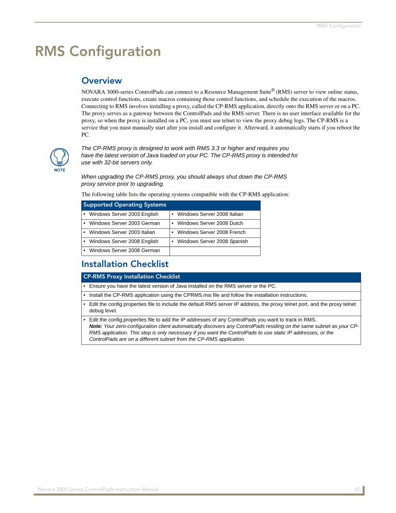
RMS Configuration
RMS Configuration
OverviewNOVARA 3000-series ControlPads can connect to a Resource Management Suite® (RMS) server to view online status, execute control functions, create macros containing those control functions, and schedule the execution of the macros. Connecting to RMS involves installing a proxy, called the CP-RMS application, directly onto the RMS server or on a PC. The proxy serves as a gateway between the ControlPads and the RMS server. There is no user interface available for the proxy, so when the proxy is installed on a PC, you must use telnet to view the proxy debug logs. The CP-RMS is a service that you must manually start after you install and configure it. Afterward, it automatically starts if you reboot the PC.
The following table lists the operating systems compatible with the CP-RMS application:
Installation Checklist
The CP-RMS proxy is designed to work with RMS 3.3 or higher and requires you have the latest version of Java loaded on your PC. The CP-RMS proxy is intended for use with 32-bit servers only.
When upgrading the CP-RMS proxy, you should always shut down the CP-RMS proxy service prior to upgrading.
Supported Operating Systems
• Windows Server 2003 English • Windows Server 2008 Italian
• Windows Server 2003 German • Windows Server 2008 Dutch
• Windows Server 2003 Italian • Windows Server 2008 French
• Windows Server 2008 English • Windows Server 2008 Spanish
• Windows Server 2008 German
CP-RMS Proxy Installation Checklist
• Ensure you have the latest version of Java installed on the RMS server or the PC.
• Install the CP-RMS application using the CPRMS.msi file and follow the installation instructions.
• Edit the config.properties file to include the default RMS server IP address, the proxy telnet port, and the proxy telnet debug level.
• Edit the config.properties file to add the IP addresses of any ControlPads you want to track in RMS. Note: Your zero-configuration client automatically discovers any ControlPads residing on the same subnet as your CP-RMS application. This step is only necessary if you want the ControlPads to use static IP addresses, or the ControlPads are on a different subnet from the CP-RMS application.
65 Novara 3000 Series ControlPads Instruction Manual
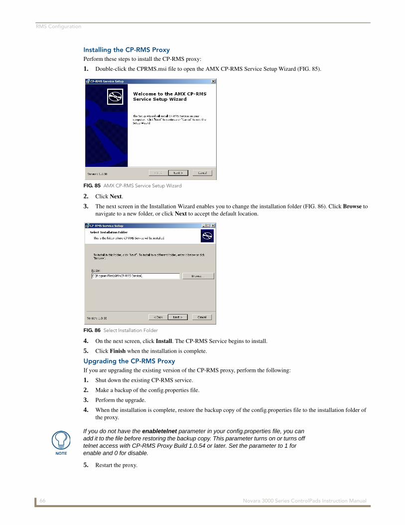
RMS Configuration
Installing the CP-RMS ProxyPerform these steps to install the CP-RMS proxy:
1. Double-click the CPRMS.msi file to open the AMX CP-RMS Service Setup Wizard (FIG. 85).
2. Click Next.
3. The next screen in the Installation Wizard enables you to change the installation folder (FIG. 86). Click Browse to navigate to a new folder, or click Next to accept the default location.
4. On the next screen, click Install. The CP-RMS Service begins to install.
5. Click Finish when the installation is complete.
Upgrading the CP-RMS ProxyIf you are upgrading the existing version of the CP-RMS proxy, perform the following:
1. Shut down the existing CP-RMS service.
2. Make a backup of the config.properties file.
3. Perform the upgrade.
4. When the installation is complete, restore the backup copy of the config.properties file to the installation folder of the proxy.
5. Restart the proxy.
FIG. 85 AMX CP-RMS Service Setup Wizard
FIG. 86 Select Installation Folder
If you do not have the enabletelnet parameter in your config.properties file, you can add it to the file before restoring the backup copy. This parameter turns on or turns off telnet access with CP-RMS Proxy Build 1.0.54 or later. Set the parameter to 1 for enable and 0 for disable.
66 Novara 3000 Series ControlPads Instruction Manual
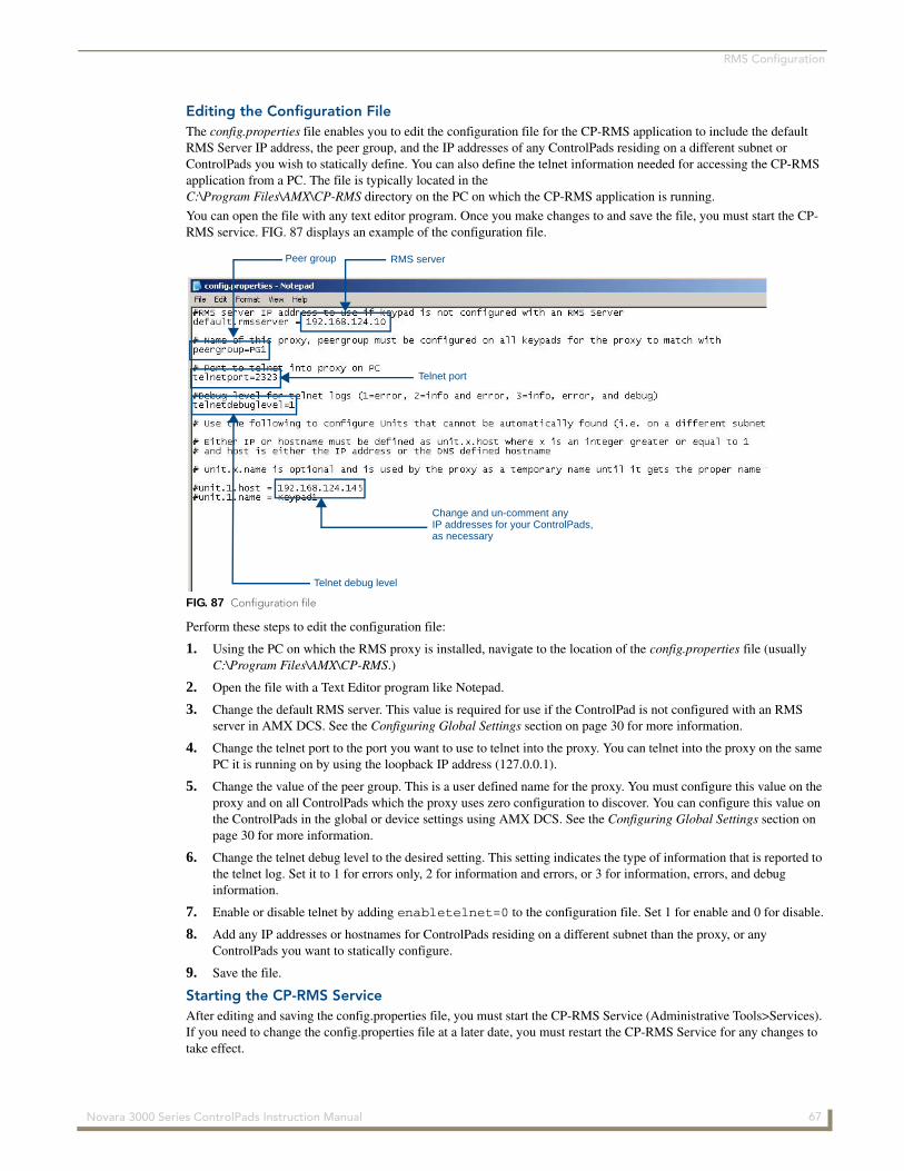
RMS Configuration
Editing the Configuration FileThe config.properties file enables you to edit the configuration file for the CP-RMS application to include the default RMS Server IP address, the peer group, and the IP addresses of any ControlPads residing on a different subnet or ControlPads you wish to statically define. You can also define the telnet information needed for accessing the CP-RMS application from a PC. The file is typically located in the C:\Program Files\AMX\CP-RMS directory on the PC on which the CP-RMS application is running.
You can open the file with any text editor program. Once you make changes to and save the file, you must start the CP-RMS service. FIG. 87 displays an example of the configuration file.
Perform these steps to edit the configuration file:
1. Using the PC on which the RMS proxy is installed, navigate to the location of the config.properties file (usually C:\Program Files\AMX\CP-RMS.)
2. Open the file with a Text Editor program like Notepad.
3. Change the default RMS server. This value is required for use if the ControlPad is not configured with an RMS server in AMX DCS. See the Configuring Global Settings section on page 30 for more information.
4. Change the telnet port to the port you want to use to telnet into the proxy. You can telnet into the proxy on the same PC it is running on by using the loopback IP address (127.0.0.1).
5. Change the value of the peer group. This is a user defined name for the proxy. You must configure this value on the proxy and on all ControlPads which the proxy uses zero configuration to discover. You can configure this value on the ControlPads in the global or device settings using AMX DCS. See the Configuring Global Settings section on page 30 for more information.
6. Change the telnet debug level to the desired setting. This setting indicates the type of information that is reported to the telnet log. Set it to 1 for errors only, 2 for information and errors, or 3 for information, errors, and debug information.
7. Enable or disable telnet by adding enabletelnet=0 to the configuration file. Set 1 for enable and 0 for disable.
8. Add any IP addresses or hostnames for ControlPads residing on a different subnet than the proxy, or any ControlPads you want to statically configure.
9. Save the file.
Starting the CP-RMS ServiceAfter editing and saving the config.properties file, you must start the CP-RMS Service (Administrative Tools>Services). If you need to change the config.properties file at a later date, you must restart the CP-RMS Service for any changes to take effect.
FIG. 87 Configuration file
Change and un-comment any
Peer group RMS server
Telnet debug level
IP addresses for your ControlPads,as necessary
Telnet port
67 Novara 3000 Series ControlPads Instruction Manual
RMS Configuration
When you configure the peer group on a ControlPad, you must restart the proxy after the ControlPad comes back online for the proxy to get an updated beacon and match peer groups.
For first time installations, you should program and configure all ControlPads that connect to a proxy using a zero-configuration client before starting the CP-RMS Service. If you are using a zero-configuration client, and the IP address of the ControlPad is changed for any reason (for example, the DHCP server assigns a different IP upon reboot of the ControlPad), the CP-RMS Service needs to be restarted for it to update the ControlPad’s IP address.
RMS Control Functions and MacrosWhen a ControlPad connects to RMS, all physical and virtual buttons that have been programmed properly with scripts and Button Assigned Names using AMX DCS display as available control functions in RMS (see the Button Actions and Events section on page 50 for more information). These control functions are available for inclusion in macros. You can schedule the macros to execute by using the RMS Internal Scheduler or an external scheduler.
When you execute a button press on the ControlPad, physically or through RMS, the script that is programmed for that button executes. The ControlPad only runs one script at a time, so if it is busy running a script and a new button event is received, the button event is ignored.
The most efficient way to execute multiple events in one macro through RMS is to create a virtual button that contains all desired events. When programming the keypad through DCS, make sure to select one of the existing RMS standard functions from the Button Assigned Name options menu or create a custom name for the virtual button. This virtual button then appears in RMS as a control function and you can create and schedule a macro, containing only that control function, in RMS.
Device InterrogationIf you program a ControlPad for device interrogation, and later re-program the ControlPad, but add a new input on a device, you must not only clear the device, re-select it, and reprogram the ControlPad from DCS, but you also need to delete the ControlPad from RMS, and restart the proxy to guarantee that the new inputs show up in the notification menus and the status is shown in the RMS server.
When the ControlPad boots up, it only runs device interrogation after the CP-RMS Proxy successfully connects to it. Additionally, the ControlPad only sends values to the CP-RMS proxy on the initial connection, and when they update. This means that for formula results, the result of the formula calculation must change at the integer/whole number level. If a device was returning lamp hours as seconds, and the formula converts seconds to hours, then the final integer result must increment or decrement to update the proxy, and ultimately RMS Server.
If a device goes offline or fails to respond to the ControlPad Status Query, no update is sent since the device is in an unknown state. A device which has lost power, or has had a disconnected serial cable, will appear online, but will never update its status.
If you add a ControlPad as a room in RMS, and then change the device name on the Controlpad to display updated information regarding the device name, you must delete the room in RMS and re-add it for the changes to appear.
68 Novara 3000 Series ControlPads Instruction Manual

RMS Configuration
69Novara 3000 Series ControlPads Instruction Manual
7/14
©20
13 A
MX
. All
right
s re
serv
ed. A
MX
and
the
AM
X lo
go
are
reg
iste
red
tra
dem
arks
of A
MX
. AM
X r
eser
ves
the
rig
ht t
o a
lter
spec
ifica
tions
with
out
no
tice
at a
ny t
ime.
3000 RESEARCH DRIVE, RICHARDSON, TX 75082 USA • 800.222.0193 • 469.624.8000 • 469-624-7153 fax • 800.932.6993 technical support • www.amx.com
Increase Your Revenuethrough education + knowledge
In the ever-changing AV industry, continual education is key to success. AMX University is dedicated to ensuring that you have the opportunity to gather the information and experience you need to deliver strong AMX solutions. Plus, AMX courses also help you earn CEDIA, NSCA, InfoComm, and AMX continuing education units (CEUs).
Visit AMX University online for 24/7/365 access to:- Schedules and registration for any AMX University course- Travel and hotel information- Your individual certification requirements and progress