Embed Size (px)
Citation preview
BG7TBL LCD-GPS DISCIPLINED OSCILLATOR
Instruction Manual
Dec. 16, 2017 @ BG7TBL, English Instruction Manual - Rogue Translation -
Version 1.1 - C
This User's Manual describes how to Install and Use the GPS Disciplined Clock
For Assistance Contact:
WUTONG electronic
Longhua, Shenzhen, Guangdong, China
Website (Chinese): http://bg7tbl.taobao.com , https://bg7tbl.world.taobao.com/
TEL/VX: 0086-134 2795 9750
Email: [email protected] , 6N2 [mailto:[email protected]] , [email protected]
2
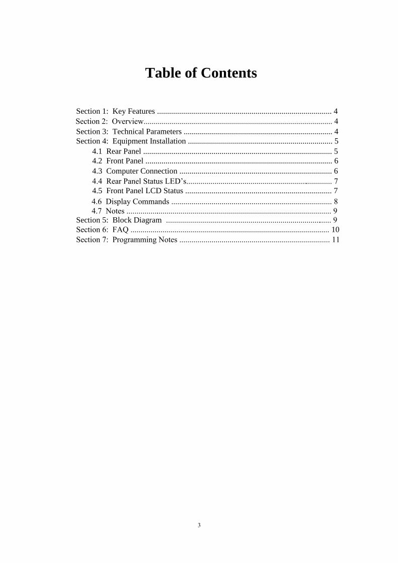
Table of Contents
Section 1: Key Features ....................................................................................... 4
Section 2: Overview.............................................................................................. 4
Section 3: Technical Parameters .......................................................................... 4
Section 4: Equipment Installation ........................................................................ 5
4.1 Rear Panel .............................................................................................. 5
4.2 Front Panel ............................................................................................. 6
4.3 Computer Connection ............................................................................ 6
4.4 Rear Panel Status LED’s......................................................................... 7 4.5 Front Panel LCD Status ......................................................................... 7
4.6 Display Commands ................................................................................ 8 4.7 Notes ....................................................................................................... 9
Section 5: Block Diagram ................................................................................... 9
Section 6: FAQ ................................................................................................... 10
3
Section 7: Programming Notes ........................................................................... 11
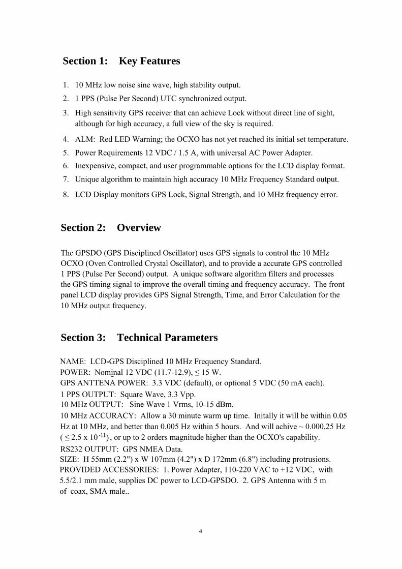
Section 1: Key Features
1. 10 MHz low noise sine wave, high stability output.
2. 1 PPS (Pulse Per Second) UTC synchronized output.
3. High sensitivity GPS receiver that can achieve Lock without direct line of sight, although for high accuracy, a full view of the sky is required.
4. ALM: Red LED Warning; the OCXO has not yet reached its initial set temperature.
6. Inexpensive, compact, and user programmable options for the LCD display format.
8. LCD Display monitors GPS Lock, Signal Strength, and 10 MHz frequency error.
Section 2: Overview
The GPSDO (GPS Disciplined Oscillator) uses GPS signals to control the 10 MHz OCXO (Oven Controlled Crystal Oscillator), and to provide a accurate GPS controlled1 PPS (Pulse Per Second) output. A unique software algorithm filters and processesthe GPS timing signal to improve the overall timing and frequency accuracy. The front panel LCD display provides GPS Signal Strength, Time, and Error Calculation for the10 MHz output frequency.
Section 3: Technical Parameters
4
5. Power Requirements 12 VDC / 1.5 A, with universal AC Power Adapter.
7. Unique algorithm to maintain high accuracy 10 MHz Frequency Standard output.
NAME: LCD-GPS Disciplined 10 MHz Frequency Standard.
POWER: Nominal 12 VDC (11.7-12.9), ≤ 15 W. - GPS ANTTENA POWER: 3.3 VDC (default), or optional 5 VDC (50 mA each).
1 PPS OUTPUT: Square Wave, 3.3 Vpp.
10 MHz OUTPUT: Sine Wave 1 Vrms, 10-15 dBm.
RS232 OUTPUT: GPS NMEA Data.
SIZE: H 55mm (2.2") x W 107mm (4.2") x D 172mm (6.8") including protrusions.
PROVIDED ACCESSORIES: 1. Power Adapter, 110-220 VAC to +12 VDC, with 5.5/2.1 mm male, supplies DC power to LCD-GPSDO. 2. GPS Antenna with 5 mof coax, SMA male..
-
-
10 MHz ACCURACY: Allow a 30 minute warm up time. Initally it will be within 0.05Hz at 10 MHz, and better than 0.005 Hz within 5 hours. And will achive ~ 0.000,25 Hz( ≤ 2.5 x 10 , or up to 2 orders magnitude higher than the OCXO's capability.
-11)
Section 4: Equipment Installation
4.1 Rear Panel
5
6
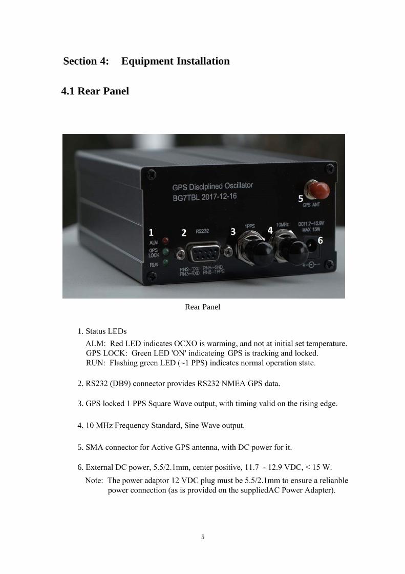
Rear Panel
1. Status LEDs
ALM: Red LED indicates OCXO is warming, and not at initial set temperature. GPS LOCK: Green LED 'ON' indicateing GPS is tracking and locked. RUN: Flashing green LED (~1 PPS) indicates normal operation state.
2. RS232 (DB9) connector provides RS232 NMEA GPS data.
3. GPS locked 1 PPS Square Wave output, with timing valid on the rising edge.
4. 10 MHz Frequency Standard, Sine Wave output.
5. SMA connector for Active GPS antenna, with DC power for it.
6. External DC power, 5.5/2.1mm, center positive, 11.7 - 12.9 VDC, < 15 W.
Note: The power adaptor 12 VDC plug must be 5.5/2.1mm to ensure a relianble
5
power connection (as is provided on the suppliedAC Power Adapter).
4.2 Front Panel
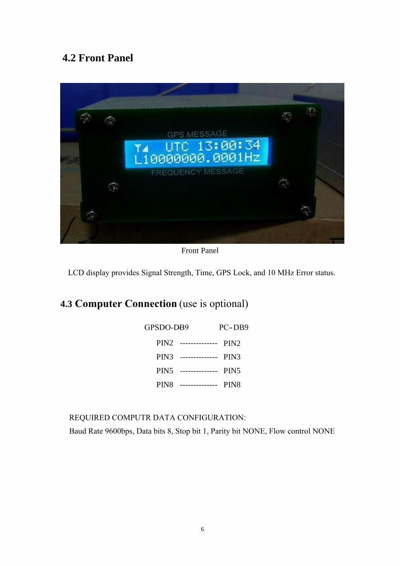
Front Panel
LCD display provides Signal Strength, Time, GPS Lock, and 10 MHz Error status.
4.3 Computer Connection
GPSDO- -DB9 PC -DB9
PIN2 -------------- PIN2
PIN3 -------------- PIN3
PIN5 -------------- PIN5
PIN8 -------------- PIN8
Baud Rate 9600bps, Data bits 8, Stop bit 1, Parity bit NONE, Flow control NONE
6
REQUIRED COMPUTR DATA CONFIGURATION:
(use is optional)
4.4 Rear Panel Status LEDs
- Power up: All three LEDs will light momentarily followed by 'RUN' (flashing), 'ALM'ON, and 'GPS Lock' OFF.
- Power up current: Less than 1.5 A.
- Preheat: The OCXO requires 30 minutes to warm up and stabilize. When it initiallyreaches operating temperature, the 'ALM' (red) will turn OFF. When the GPS is Locked,tthe 'GPS Lock' (green) will turn ON indicating normal operation is in process.
-- Normal: 'RUN' (green) flashing, 'GPS Lock' (green) ON. 'ALM' (red) OFF, means that the GSDO is operating normally.
4.5 Front Panel LCD Display Status Indications
1 2 3
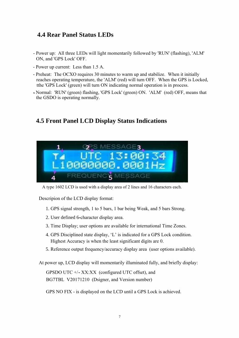
4 5 A type 1602 LCD is used with a display area of 2 lines and 16 characters each.
1. GPS signal strength, 1 to 5 bars, 1 bar being Weak, and 5 bars Strong.
2. User defined 6-character display area.
3. Time Display; user options are available for international Time Zones.
4. GPS Disciplined state display, ‘L’ is indicated for a GPS Lock condition.Highest Accuracy is when the least significant digits are 0.
5. Reference output frequency/accuracy display area (user options available).
At power up, LCD display will momentarily illuminated fully, and briefly display:
GPSDO UTC +/- XX:XX (configured UTC offset), and
GPS NO FIX - is displayed on the LCD until a GPS Lock is achieved.
7
-
Descripion of the LCD display format:
-
BG7TBL V20171210 (Dsigner, and Version number)
4.6 Display Commands - User Display Options
- An Internal 'Run/Test Mode Jumper' must set to the Test Mode for programming.Test Mode is enabled by placing a connection across this Jumper (on main PCB behind the 3 LEDs)
The instructions are in 'ASCII code' starting with: $GPGTC’, then 12 bits (X1-X12), and ending with ‘T*
$GPGTC, X1 X2 X3 X4 X5 X6 X7 X8 X9 X10 X11 X12 T* X1, sets frequency display mode:
‘0’ for “10000000.0000 Hz” format ‘1’ for “10M +/- 0.0000 Hz” format ‘2’ for “10M +/- 000.00 ppb” format (i.e. 001.00 = 1 x 10 ‘3’ for “10M +/- 0.00000 ppm” format
X2 - X7, sets the user defined 6-character area X8, sets positive time offset from UTC ‘+’ (default is +, e.g. +0000) X9 & X10, two digit hour offset, ‘00’ to ‘23’ (default 00, for UTC Time) X11 & X12, two-digit minute offset, ’00’ to ‘59’ (default is 00, seldom ever changed ) - Example 1: PPM frequency format display mode, w/UTC displayed as 'BJT' (Beijing)Time, with a time offset of 8:00 hours, the command would be;
$GPGTC,3 BJT +0800T*
- Example 2: 10000000.0000 Hz frequency format display mode, with UTC Time display,without a time offset, the command would be;
$GPGTC,0 UTC +0000T*
-with a time offse of 5:00 hours, the command would be;
$GPGTC,2 EST +0500T*
After a command is sent and executed successfully, the device will return an ‘OK’ reply.
8
-9 ) -11, 000.01 = 1 x 10(i.e. 1.00000 = 1 x 10 -6 )
Configure a PC for Terminal emulation with an appropriate software utility* (see Section7, Programming Notes.
- User LCD Display Programming basic command string ($) structure follows:
When LCD display programming has been completed, remove the PC connection, and setthe 'Test Mode Jumper' to the normal 'Run Mode' (Open). Recycle the GPSDO DC Power(OFF/ON), and the GPSDO should boot-up using the new LCD Display Option format.
-
-
Note: The following command strings use 1 Space before 'UTC' and 2 Spaces after.
NOTE ! All basic command strings ($) for programming need to tbe copied twice (2x)into the TX Send [field] of the Terminal Emulator (witout a space between them).i.e. Copy $GPGTC,0 GMT +0000T* twice for sending to the GPSDO as follows:$GPGTC,0 GMT +0000T*$GPGTC,0 GMT +0000T* (two basic comand strings as one)
Example 3: PPB frequency format display mode, with EST Ttime display,-
-
-
-
-
-
4.7 Notes
The LCD display for the Frequency Standard's frequency, or error, is a calculated value,and as such, there may be a deviation from its actual frequency.
The GPSDO surface will become Warm (not HOT) during operation, and this is normal.
For optimum GPS signal Lock, place the antenna for a clear view of the sky, avoidpotential interference sources such as high voltage power lines, etc. GPS Lock may beobtained without a full view of the sky, although with a potential for degradation infrequency accuracy.
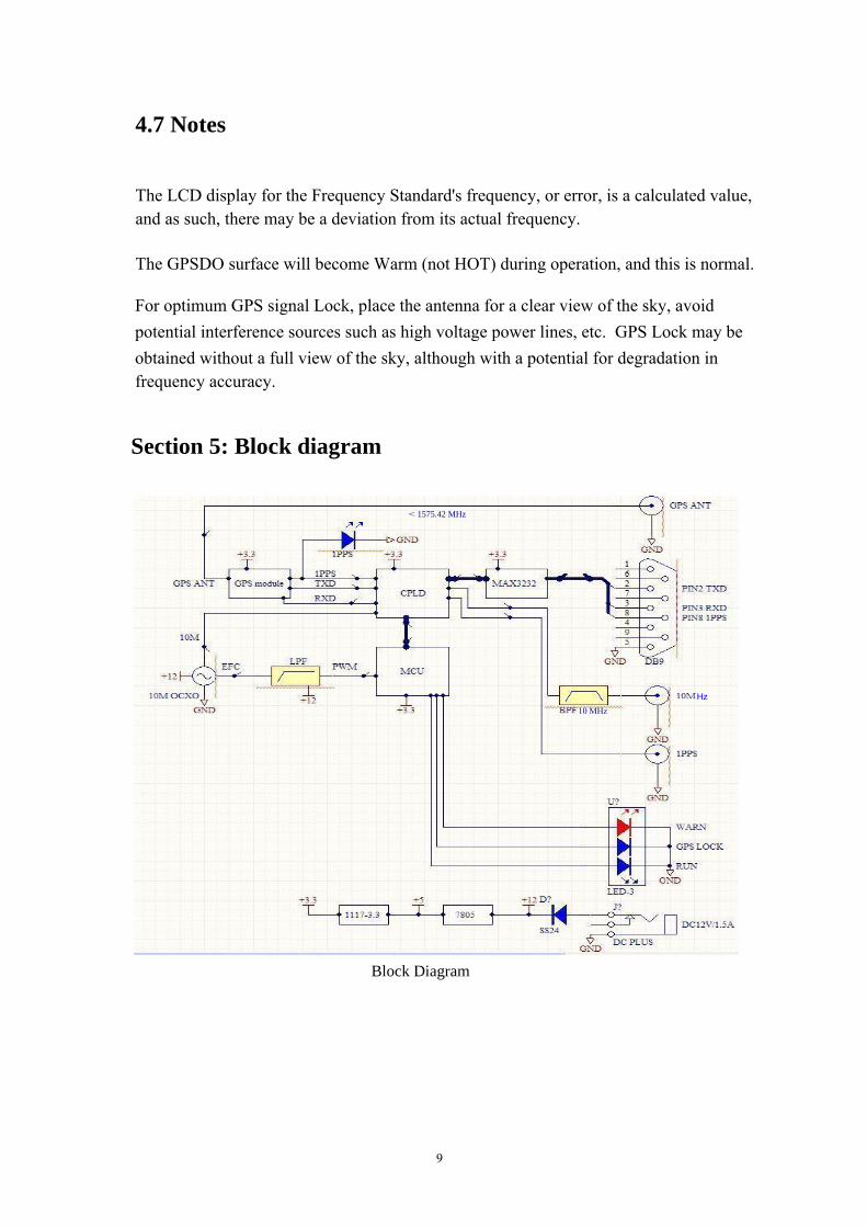
Section 5: Block diagram
< 1575.42 MHz
Hz
10 MHz
Block Diagram
9
Section 6: FAQ
Q : How can I tell if the device is working?
A : After powering ON for serveral minutes, the ALM (red) LED should turn off.
Q : How can I tell if the MCU is working?
A : When powered ON, all the LEDs will light momentarily, then the RUN (green) LED
will be flashing, and the ALM (red) will be lit, indicating the MCU is operating.
Q :The 5m GPS active antenna cable is too short for connecting it to the GPSDO?
A : An appropriate 50 Ohm coax extension cable with SMA M/F connectors can be used.
The GPSDO will operate in if the GSP antenna isn't connected, or the GPS signalsare lost for any reason. In this event, GPS NO FIX is displayed, and the frequencyaccuracy may be degraded.
Q : I use a frequency counter and the frequency of the device shows a difference, what
should I do?
A : The LCD frequency of the device is from a internal calculation, the actual test frequency
may have a deviation. However, when the machine displays L10000000.0000 Hz the the accuracy is high. For verification measurement, ensure that the reference frequencymeasurement device's accuracy is at least good for +/- 0.000,01 Hz. A frequencycounter should have an accuracy of at least 10 times better than the expectation of the device being measured.
Q : The displayed GPS signal strength changes from high, to low, etc.
A : Some of this is normal. The signal strength is affected by the satellite locations,weather (rain, snow, etc), and any signal absorption, or reflections.
10
10 10 10 10 10 10 10 10 10 10 10 10 10 10 10 10 10
11
Section 7: Programming Notes
'Master Reset' command for the BG7TBL LCD-GPSDO: To Initialize Factory Defaults.Send > 00000000000000000000000000$GPGTC,0 UTC +0000T* twice in a single $(this command leads with 26 Zeros, then One Space before "UTC", Two Spaces after)
Termite' Terminal Emulator, is a proven application for programming the LCD-GPSDO.It is a freeware, portable app. that doesn't require installation, and can be run from aUSB Thumb drive. Available at > https://www.compuphase.com/software_termite.htm Terminal Emulattor Configuration: Baud Rate 9600bps, Data bits 8, Stop bit 1,Parity bit NONE, Flow control NONE. Connect PC to the Rear Panel RS232 connector. A inexpensive 'USB to Serial Port(RS232) Adapter Cable' works well for programming using a PC without a Serial Port.
The full command to send is as follows:00000000000000000000000000$GPGTC,0 UTC +0000T*00000000000000000000000000$GPGTC,0 UTC +0000T*
Remember:LCD Display Option Programming Commands are to be sent as a double basic string,without a space between them. This a firmware programming verification requirementto help ensure that only valid commands are executed.
1. Potentiometer RP1 on the Display Board is a Contrast adjustment for the LCD. 2. To configure the GPSDO to supply 5 VDC to the GPS Antenna (vs. default 3.3 VDC) for a 5 VDC Active GPS Antenna. Move the SMT Fuse from 'ANT 3.3V' to the 'ANT 5V' location. These are clearly marked on the bottom of the Main PCB, next to the U-blox GPS Receiver IC.3. GPS NO FIX is displayed on the LCD when the GPS isn't Lock'ed.4. The character '$' is used to represent a ASCII string command.
Miscellaneous:
Recommendation:
LCD Display Option Pgm. Commands:1. Display UTC Time, with Frequency in Hz (defaut, as supplied) $GPGTC,0 UTC +0000T*$GPGTC,0 GMT +0000T* 2. Display UTC Time, with Frequency Error in PPB (recommended) $GPGTC,2 UTC +0000T*$GPGTC,2 GMT +0000T*3. Display EST Time, with Frequency Error in PPB $GPGTC,2 EST +0500T*$GPGTC,2 EST +0500T*
Ready to paste into Terminal [TX Field]