Embed Size (px)
Citation preview

INSTRUCTION MANUALMeade114 EQ-ASB4.5" Equatorial Reflecting Telescope
Meade Instruments Corporation

– 2 –
WARNING! NEVER USE A MEADE 114 EQ-ASBTELESCOPE TO LOOK AT THE SUN! LOOKING AT ORNEAR THE SUN WILL CAUSE INSTANT AND
IRREVERSIBLE DAMAGE TO YOUR EYE. EYE DAMAGE IS OFTENPAINLESS, SO THERE IS NO WARNING TO THE OBSERVER THATDAMAGE HAS OCCURRED UNTIL IT IS TOO LATE. DO NOT POINTTHE TELESCOPE OR ITS VIEWFINDER AT OR NEAR THE SUN. DONOT LOOK THROUGH THE TELESCOPE OR ITS VIEWFINDER AS ITIS MOVING. CHILDREN SHOULD ALWAYS HAVE ADULTSUPERVISION WHILE OBSERVING.
Meade Limited Warranty
Every Meade telescope, spotting scope, and binocular is warranted by Meade Instruments Corp. (MIC) to be free ofdefects in materials and workmanship for a period of ONE YEAR from date of original retail purchase in the U.S.A.MIC will repair or replace the product, or part thereof, found upon inspection by MIC to be defective, provided thedefective part or product is returned to MIC, freight prepaid, with proof of purchase. This warranty applies to theoriginal purchaser only and is non-transferable. Meade products purchased outside North America are notincluded in this warranty, but are covered under separate warranties issued by Meade InternationalDistributors.
RGA Number Required: Prior to the return of any product or part, a Return Goods Authorization (RGA) number mustbe obtained by writing to MIC or calling 949-451-1450. Each returned part or product must include a written statementdetailing the nature of the claimed defect, as well as the owner’s name, address, phone number, and a copy of theoriginal sales invoice.
This warranty is not valid in cases where the product has been abused or mishandled, where unauthorized repairshave been attempted or performed, or where depreciation of the product is due to normal wear-and tear. MICspecifically disclaims special, indirect, or consequential damages or lost profit, which may result from a breach of thiswarranty. Any implied warranties which cannot be disclaimed are hereby limited to a term of one year from the date ofpurchase by the original retail purchaser.
This warranty gives you specific rights. You may have other rights which vary from state to state.
MIC reserves the right to change product specifications or to discontinue products without prior notice.
This warranty supersedes all previous Meade product warranties.

– 3 –
TABLE OF CONTENTS
Introduction . . . . . . . . . . . . . . . . . . . . . . . . . . . . 6
This Manual . . . . . . . . . . . . . . . . . . . . . . . . . . . . . . . . . . . . . . . . 6
Standard Equipment . . . . . . . . . . . . . . . . . . . . . . . . . . . . . . . . . . 6
Unpacking and Assembly . . . . . . . . . . . . . . . . . . . . . . . . . . . . . . . . . . . 6
Balancing the Telescope . . . . . . . . . . . . . . . . . . . . . . . . . . . . . . . 7
Alignment of the Viewfinder. . . . . . . . . . . . . . . . . . . . . . . . . . . . . 7
Understanding Celestial Movements and Coordinates. . . . . . . . . . . . . . 8
Lining Up with the Celestial Pole. . . . . . . . . . . . . . . . . . . . . . . . . . . . . . 9
Using the Telescope . . . . . . . . . . . . . . . . . . . . . . . . . . . . . . . . . . . . . . . 9
Using Setting Circles. . . . . . . . . . . . . . . . . . . . . . . . . . . . . . . . . . . . . . 11
Calculating Power . . . . . . . . . . . . . . . . . . . . . . . . . . . . . . . . . . . . . . . . 11
Maintenance. . . . . . . . . . . . . . . . . . . . . . . . . . . . . . . . . . . . . . . . . . . . 12
Cleaning. . . . . . . . . . . . . . . . . . . . . . . . . . . . . . . . . . . . . . . . . . 12
Mount and Tripod Adjustments . . . . . . . . . . . . . . . . . . . . . . . . . 12
Collimation . . . . . . . . . . . . . . . . . . . . . . . . . . . . . . . . . . . . . . . . 12
a. Correct Collimation . . . . . . . . . . . . . . . . . . . . . . . . . . . . . . . 12
b. Diagonal Holder Adjustments . . . . . . . . . . . . . . . . . . . . . . . 12
c. Primary Mirror Adjustments. . . . . . . . . . . . . . . . . . . . . . . . . 13
d. Star Testing the Collimation . . . . . . . . . . . . . . . . . . . . . . . . 13
Specifications . . . . . . . . . . . . . . . . . . . . . . . . . . . . 15
Optional Accessories . . . . . . . . . . . . . . . . . . . . . . . . . . . . . . . . . . . . . 15
– 4 –
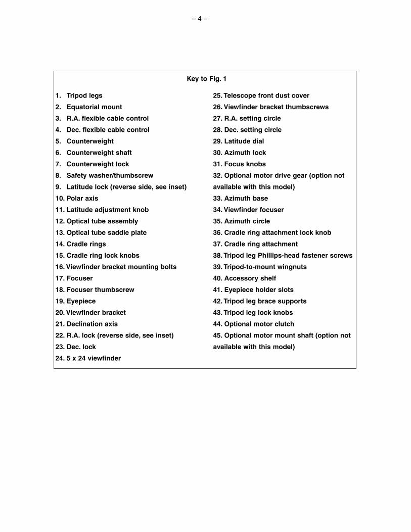
1. Tripod legs
2. Equatorial mount
3. R.A. flexible cable control
4. Dec. flexible cable control
5. Counterweight
6. Counterweight shaft
7. Counterweight lock
8. Safety washer/thumbscrew
9. Latitude lock (reverse side, see inset)
10. Polar axis
11. Latitude adjustment knob
12. Optical tube assembly
13. Optical tube saddle plate
14. Cradle rings
15. Cradle ring lock knobs
16. Viewfinder bracket mounting bolts
17. Focuser
18. Focuser thumbscrew
19. Eyepiece
20. Viewfinder bracket
21. Declination axis
22. R.A. lock (reverse side, see inset)
23. Dec. lock
24. 5 x 24 viewfinder
25. Telescope front dust cover
26. Viewfinder bracket thumbscrews
27. R.A. setting circle
28. Dec. setting circle
29. Latitude dial
30. Azimuth lock
31. Focus knobs
32. Optional motor drive gear (option not
available with this model)
33. Azimuth base
34. Viewfinder focuser
35. Azimuth circle
36. Cradle ring attachment lock knob
37. Cradle ring attachment
38. Tripod leg Phillips-head fastener screws
39. Tripod-to-mount wingnuts
40. Accessory shelf
41. Eyepiece holder slots
42. Tripod leg brace supports
43. Tripod leg lock knobs
44. Optional motor clutch
45. Optional motor mount shaft (option not
available with this model)
Key to Fig. 1
– 5 –
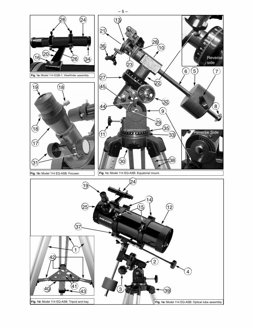
Fig. 1a: Model 114 EQB-1: Viewfinder assembly.
4
340 4143
38
56 7
8
10
11
13
17
18
18
19
21
23
24
20
25
26
27
28
3031
45
33
37
29
14
2
36
3244
15
24
1
39
19
16 26 34
9
35
12
42
Fig. 1b: Model 114 EQ-ASB: Focuser. Fig. 1c: Model 114 EQ-ASB: Equatorial mount.
Fig. 1d: Model 114 EQ-ASB: Tripod and tray. Fig. 1e: Model 114 EQ-ASB: Optical tube assembly.
22
Reverseside
Reverse Side

– 6 –
INTRODUCTIONThe Meade 114 EQ-ASB is an easy-to-operate, high performance 4.5" (114mm) reflecting telescope,intended for astronomical observing. Equipped with a deluxe equatorial mount and aluminum tripod, thetelescope’s motion is continuously adjustable for tracking celestial objects. Your telescope comes to youready for adventure; it will be your companion in a universe of planets, galaxies, and stars. Please notethat the Meade 114 EQ-ASB is a Newtonian reflecting telescope optimized for astronomical observingperformance, and is not intended for terrestrial observing.
This ManualThese instructions detail the set-up, operation, specifications, and optional accessories of your Jupiter114 EQ-ASB. In order that you may achieve maximum enjoyment of the instrument, we urge thatyou take a few minutes to read all of this manual before making first observations through the telescope.
Standard Equipment• Complete optical tube assembly with a 4.5" (114mm) diameter primary mirror, viewfinder mounting
bolts with mounting nuts and rack-and-pinion focuser. Mirror focal length = 1000mm; f/8.8• Equatorial mount with pre-attached heavy duty, continuously adjustable, aluminum tripod and leg
braces.• Accessories: MA25mm eyepiece (1.25" O.D.), MH9mm eyepiece (1.25" O.D.),
2x Barlow lensCradle rings with lock knobs5 x 24 viewfinder and bracketCounterweight with counterweight shaftFlexible cable controls for both telescope axesAccessory trayCD-Rom with Astronomy Software
UNPACKING AND ASSEMBLYYour Meade 114 EQ-ASB comes to you packaged almost entirely pre-assembled. (References in thissection—e.g. (6)—are to Fig.1a - 1e unless otherwise specified.)
• Remove and identify the telescope’s Standard Equipment listed above.
• The three tripod lock knobs (43) have been removed from thebottom section of each tripod leg to insure safe arrival of the tripodassembly. To install, thread in each tripod lock knob into thethreaded hole located at the right side of each of the threecastings (see Fig. 1f) at the bottom of each tripod leg. Tighten thetripod lock knob only to a “firm feel” to avoid damage to the tripodcaused by overtightening.
• Spread the tripod legs (1) to full extension so that the leg braces(42) are taut (should one of the tripod leg braces slip out of thecenter triangle fastener, merely reposition the brace and slide itback into position). Adjust the tripod with the attached equatorialmount (2) to the desired height by loosening the tripod lock knobs and extend the sliding inner sectionof each tripod leg; then tighten each knob.
• Attach the flexible cable controls (3) and (4). These cable controls are secured in place with a firmtightening of the thumbscrew located at the end of each cable.
• Holding the counterweight (5) firmly in one hand, slip the counterweight onto the counterweight shaft(6). Attach the counterweight (5) and counterweight shaft (6), by supporting the unlocked (7)counterweight firmly in one hand, while threading the counterweight shaft into the base of theDeclination axis of the telescope’s equatorial mount with the other (see Fig. 1). Once firmly attached,slide the counterweight to the midpoint on the counterweight shaft and secure it in place with the lockknob (7) of the counterweight. Note: If the counterweight ever slips, the secured threaded safetywasher/knob (8) will not let the weight slide entirely off the counterweight shaft. Be certain that thissafety washer/knob is always in place.
• Release the latitude lock (9) of the equatorial mount, and tilt the polar axis (10) of the telescope toroughly a 45° angle by turning the latitude adjustment knob (11). With the polar axis thus tilted, firmlyre-tighten the latitude lock.
Trou taraudé
Bouton de blocagePartie intérieure coulissante
Fig. 1f: Tripod lock knob assembly.
Threaded Hole
Leg Lock Knob
Sliding Inner Leg

– 7 –
• Remove the viewfinder bracket mounting nuts from the viewfinder bracket mounting bolts (16) thatprotrude from the optical tube (12), near the focuser (17). Place the viewfinder bracket’s mountingholes (located at the base of the bracket) over the mounting bolts, so that the bracket is oriented asshown in Fig. 1. Replace the viewfinder bracket mounting nuts, and tighten to a firm feel. Then centerthe viewfinder in both bracket rings by backing off the three thumbscrews (26) on each bracket ring.Orient the viewfinder so its front objective lens is pointing in the same direction as the open end (front)of the optical tube (25).
• Position the cradle ring attachment (37) onto the optical tube saddle plate (13), with the mid-point lyingroughly in the center of the saddle plate. Tighten the cradle ring lock knob (36) to a firm feel when thecradle ring attachment is positioned in the telescope’s saddle (13).
• If the cradle ring assmbly did not come already attached to the optical tube assembly (12), loosen thelock knobs (15) of the cradle rings (14) and open the cradle rings. Place the optical tube assemblyroughly in the center of the cradle rings and close the rings over the tube. Then tighten the cradle ringlock knobs (15) to a firm feel; do not overtighten these knobs. Please note that you may want to changethe rotational position of the optical tube to gain a more comfortable observing position of the focuser(17). This adjustment may be performed several times in one observing session, as desired.
• Insert the 25mm eyepiece (19) into the focuser, and tighten the focuser thumbscrew (18) to secure theeyepiece.
The telescope is now fully assembled. Before it can be properly used, however, the telescope must bebalanced and the viewfinder aligned.
Balancing the TelescopeIn order for the telescope to move smoothly on its mechanical axes, it must first be balanced about the 2telescope axes: the polar axis (10, Fig. 1c) and the Declination axis (21, Fig. 1c). All motions of the polaraligned telescope (more on this later) take place by moving about these two axes, separately orsimultaneously. To obtain a fine balance of the telescope, follow the method below:
• Loosen the R.A. lock (22, Fig. 1c) and rotate the telescope so that the counterweight shaft (6, Fig. 1c)is parallel to the ground (horizontal).
• Slide the counterweight along the counterweight shaft until the telescope remains in one positionwithout tending to drift down in either direction. Then tighten the counterweight lock knob (7, Fig. 1c),locking the counterweight in position.
• Lock the R.A. lock (22, Fig. 1c), and unlock the Declination lock (23, Fig. 1c). The telescope will nowturn freely about the Declination axis. Loosen the cradle ring lock knobs (15, Fig. 1e) so that the maintube in the cradle rings slides easily up-or-down in the cradle rings. Move the main tube in the cradlerings until it is balanced rotationally about the Declination axis. Re-lock the knobs (15, Fig. 1e).
The telescope is now properly balanced on both axes.
Alignment of the ViewfinderThe wide field of view provided by the 5 x 24mm viewfinder permits easy object sighting prior toobservation in the higher-power main telescope. The 5 x 24 Viewfinder (24, Fig. 1a) and viewfinder bracket(20, Fig. 1a) attaches to the telescope tube assembly as described above (see Fig. 1a). In order for theviewfinder to be functional, however, it must be aligned to the main telescope, so that both the viewfinderand main telescope point at the same position in the sky. With this simple alignment performed, findingobjects is greatly facilitated, since you will first locate an object in the wide-field viewfinder, then you willlook in the eyepiece of the main telescope for a detailed view. To align the viewfinder follow these steps:• Remove the telescope front dust cover (25, Fig. 1e), and the dust covers of the viewfinder.
• Place the low- power (25mm) eyepiece into the focuser of the main telescope.
• Unlock the R.A. lock (22, Fig. 1c) and the Dec. lock (23, Fig. 1c) so that the telescope turns freely onboth axes. Then point the main telescope at some well-defined land object (e.g. the top of a telephonepole) at least 200 yards distant, and re-lock the R.A and Dec. axes. Turn the flexible cable controls, (3,Fig. 1e) and (4, Fig. 1e), to center the object in the telescopic field.
• With the front of the viewfinder already centered in the front bracket ring, look through the viewfinderand loosen or tighten, as appropriate, one or more of the rear viewfinder bracket ring thumbscrews(26, Fig. 1a) until the viewfinder’s crosshairs are likewise centered on the object previously centeredin the main telescope.

– 8 –
• Check this alignment on a celestial object, such as a bright star or the Moon, and make anyrefinements necessary, using the method outlined above.
With this alignment performed, objects first located in the wide-field viewfinder will also be centered in themain telescope’s field of view. (Note: The viewfinder presents an image which is upside-down.)
UNDERSTANDING CELESTIAL MOVEMENTS AND COORDINATESUnderstanding where to locate celestial objects, and how those objects move across the sky isfundamental to enjoying the hobby of astronomy. Most amateur astronomers adopt the simple practice of“star-hopping” to locate celestial objects by using star charts or astronomical software which identify brightstars and star patterns (constellations) that serve as “road maps” and “landmarks” in the sky. These visualreference points guide amateur astronomers in their search for astronomical objects. And while star-hopping is the preferred technique, a discussion of using setting circles for locating objects is desirablesince your telescope is provided with this feature. However, be advised, compared to star-hopping, objectlocation by use of setting circles requires a greater investment in time and patience to achieve a moreprecise alignment of the telescope’s polar axis to the celestial pole. For this reason, in part, star-hoppingis popular because it is the faster, easier way to become initiated in the hobby.
Understanding how astronomical objects move: Due to the Earth’s rotation, celestial bodies appear tomove from East to West in a curved path through the skies. The path they follow is known as their line ofRight Ascension (R.A.). The angle of this path they follow is known as their line of Declination (Dec.).
A celestial coordinate system was created that maps an imaginary sphere surrounding the Earth uponwhich all stars appear to be placed. This mapping system is similar to the system of latitude and longitudeon Earth surface maps.
In mapping the surface of the Earth, lines of longitude are drawn between the North and South Poles andlines of latitude are drawn in an East-West direction, parallel to the Earth’s equator. Similarly, imaginarylines have been drawn to form a latitude and longitude grid for the celestial sphere. These lines are knownas Right Ascension and Declination.
The celestial map also contains two poles and an equator just like a map of the Earth. The poles of thiscoordinate system are defined as those two points where the Earth’s North and South poles (i.e., theEarth's axis), if extended to infinity, would cross the celestial sphere. Thus, the North Celestial Pole (seeFig. 3) is that point in the sky where an extension of the North Pole intersects the celestial sphere. TheNorth Star, Polaris, is located very near the North Celestial Pole. The celestial equator is a projection of theEarth’s equator onto the celestial sphere.
So just as an object's position on the Earth’s surface can be located by its latitude and longitude, celestialobjects may also be located using Right Ascension and Declination. For example: You could locate LosAngeles, California, by its latitude (+34°) and longitude (118°). Similarly, you could locate the Ring Nebula(also known as “M57”) by its Right Ascension (18hr) and its Declination (+33°).
n Right Ascension (R.A.): This celestial version of longitude is measured in units of hours (hr), minutes(min), and seconds (sec) on a 24-hour "clock" (similar to how Earth's time zones are determined bylongitude lines). The "zero" line was arbitrarily chosen to pass through the constellation Pegasus, a sortof cosmic Greenwich meridian. R.A.coordinates range from 0hr 0min0sec to 23hr 59min 59sec. There are24 primary lines of R.A., located at15-degree intervals along thecelestial equator. Objects locatedfurther and further East of the zeroR.A. grid line (0hr 0min 0sec) carryhigher R.A. coordinates.
n Declination (Dec.): This celestialversion of latitude is measured indegrees, arc-minutes, and arc-seconds (e.g., 15° 27' 33"). Dec.locations North of the celestialequator are indicated with a plus (+)sign (e.g., the Dec. of the Northcelestial pole is +90°). Dec. locations
1415
1617
1819
2021
22 23 0 1
12 11 109
87
56
43
2
13
Rotation de la Terre
0° Déc.
Pôle céleste Sud.
Ascension droite
Etoile
Equateur céleste
Déc.-90° Déc.
+90° Déc.Pôle nord céleste
Déclinaison
Fig. 2: Celestial Sphere.
North Celestial Pole(Vicinity of Polaris)
+90° Dec.
Star
Celestial Equator
-90° Dec.
South Celestial Pole

South of the celestial equator are indicated with a minus (–) sign (e.g., the Dec. of the South celestialpole is –90°). Any point on the celestial equator (such as the the constellations of Orion, Virgo, andAquarius) is said to have a Declination of zero, shown as 0° 0' 0."
With all celestial objects therefore capable of being specified in position by their celestial coordinates ofRight Ascension and Declination, the task of finding objects (in particular, faint objects) in the telescope isvastly simplified. The setting circles, R.A (27, Fig. 1c) and Dec. (28, Fig. 1c) of the Polaris 114 EQ-ASBtelescope may be dialed, in effect, to read the object coordinates and the object found without resorting tovisual location techniques. However, these setting circles may be used to advantage only if the telescopeis first properly aligned with the North Celestial Pole.
LINING UP WITH THE CELESTIAL POLEObjects in the sky appear to revolve around the celestial pole. (Actually, celestial objects are essentially“fixed,” and their apparent motion is caused by the Earth’s axial rotation). During any 24 hour period, starsmake one complete revolution about the pole, making concentric circles with the pole at the center. Bylining up the telescope’s polar axis with the North Celestial Pole (or for observers located in Earth’sSouthern Hemisphere with the South Celestial Pole), astronomical objects may be followed, or tracked, bymoving the telescope about one axis, the polar axis.
If the telescope is reasonably well aligned with the pole, therefore, very little use of the telescope’sDeclination flexible cable control is necessary and virtually all of the required telescope tracking will be inRight Ascension. (If the telescope were perfectly aligned with the pole, no Declination tracking of stellarobjects would be required). For the purposes of casual visual telescopic observations, lining up thetelescope’s polar axis to within a degree or two of the pole is more than sufficient: with this level of pointingaccuracy, the telescope can track accurately by slowly turning the telescope’s R.A. flexible cable controland keep objects in the telescopic field of view for perhaps 20 to 30 minutes.
To line up the Meade 114 EQ-ASB with the pole, follow this procedure:1. Release the Azimuth lock (30, Fig. 1c) of the Azimuth base (33, Fig. 1c), so that the entire telescope-
with-mounting may be rotated in a horizontal direction. Rotate the telescope until the polar axis (10,Fig. 1c) points due North. Locate Polaris, the North Star (see Fig. 3), as an accurate reference for dueNorth.
2. Level the mount, if necessary, by adjusting theheights of the three tripod legs. Set the Dec dialto 90°.
3. Determine the latitude of your observing location bychecking a road map or atlas. Release thelatitude lock (9, Fig. 1c) and tilt the telescopemount with the latitude adjustment knob (11, Fig.1) so that the pointer indicates the correct latitudeof your viewing location on the latitude scale (29,Fig. 1c). Re-tighten the latitude lock (9, Fig. 1c).
4. Without moving the telescope on the Right Ascension and Declination axes, loosen the azimuth andlatitude locks (9 and 30, Fig. 1c) and adjust the telescope until Polaris is centered in the telescopeeyepiece. If steps 1 - 3 above were performed with reasonable accuracy, your telescope is nowsufficiently well-aligned to the North Celestial Pole for visual observations.
Once the mount has been polar-aligned as described above, the latitude angle need not be adjusted again,unless you move to a different geographical location (i.e. a different latitude). The only polar alignmentprocedure that need be done each time you use the telescope is to point the polar axis due North, asdescribed in step 1 above.
USING THE TELESCOPEWith the telescope assembled, balanced and polar aligned as described above, you are ready to beginobservations. Decide on an easy-to-find object such as the Moon, if it is visible, or a bright star to becomeaccustomed to the functions and operations of the telescope. For the best results during observations,follow the suggestions below:
– 9 –
Polaire
Grande Ourse
Petite Ourse
Cassiopée
Fig. 3: Locating Polaris.
Little DipperPolaris
Big Dipper Cassiopeia

– 10 –
• To center an object in the main telescope, loosen the telescope’s R.A. lock (22, Fig. 1c) and Dec. lock(23, Fig. 1c). The telescope can now turn freely on its axes. Use the aligned viewfinder to first sight-inon the object you wish to observe; with the object centered on the viewfinder’s crosshairs, re-tighten theR.A. and Dec. locks.
• If you have purchased an assortment of eyepieces (see Section G on Calculating Power and Section Jon Optional Accessories for higher and lower powers with the telescope), always start an observationwith a low power eyepiece (e.g., the 25mm eyepiece); get the object well-centered in the field of viewand sharply focused. Then try the next step up in magnification. If the image starts to become fuzzy asyou work into higher magnifications, then back down to a lower power; the atmospheric steadiness is notsufficient to support high powers at the time you are observing. Keep in mind that a bright, clearlyresolved but smaller image will show far more detail than a dimmer, poorly resolved larger image. The25mm eyepiece included with the Meade 114 EQ-ASB presents a wide field of view, ideal for generalastronomical observing of star fields, clusters of stars, nebulae, and galaxies; it is also probably the besteyepiece to use in the initial finding and centering of any object.
• Once centered, the object can be focused by turning one of the knobs of the focusing mechanism (31,Fig. 1b). You will notice that the astronomical object in the field of view will begin to slowly move acrossthe eyepiece field. This motion is caused by the rotation of the Earth on its axis, as described in SectionC, although the planets and stars, are, for practical purposes, fixed in their positions in the sky. Theplatform on which the telescope is sitting ( the Earth) rotates once every 24 hours under these objects.To keep astronomical objects centered in the field of the polar aligned telescope, simply turn theR.A. flexible cable control (3, Fig. 1e). These objects will appear to move through the field more rapidlyat higher powers. Note that the Declination flexible cable control (4, Fig. 1e) is used only for centeringpurposes, and not for tracking.
• Avoid touching the eyepiece while observing through the telescope. Vibrations resulting from suchcontact will cause the image to move. Likewise, avoid observing sites where ground-based vibrationsmay resonate the tripod. Viewing from the upper floors of a building may also introduce imagemovement.
• You should allow a few minutes to allow your eyes to become “dark adapted” before attempting anyserious astronomical observations. Use a red filtered flashlight to protect your night vision when readingstar maps or inspecting the components of the telescope.
• Avoid setting up the telescope inside a room and observing through an open window (or worse yet, aclosed window). Images viewed in such a manner may appear blurred or distorted due to temperaturedifferences between inside and outside air. Also, it is a good idea to allow your telescope a chance toreach the ambient (surrounding) outside temperature before starting an observing session.
• Avoid viewing objects low on the horizon–objects will appear better resolved with far greater contrastwhen viewed higher in the sky. Also, if images appear to “shimmer” in the eyepiece–reduce power untilthe image steadies. This condition is caused by air turbulence in the upper atmosphere. We repeat thewarning stated at the outset of this manual:
Never point the telescope directly at or near the Sun at any time! Observing the Sun, even for thesmallest fraction of a second, will result in instant and irreversible eye damage, as well as physicaldamage to the telescope itself.
The Meade 114 EQ-ASB may be used for a lifetime of rewarding astronomical observing, but basic to yourenjoyment of the telescope is a good understanding of the instrument. Read the above instructions carefullyuntil you understand all of the telescope’s parts and functions. One or two observing sessions will serve toclarify these points forever in your mind.The number of fascinating objects visible through your Jupiter reflector is limited only by your own motivation.Astronomical software, such as Polaris’s AstroSearch, or a good star atlas, will assist you in locating manyinteresting celestial objects. These objects include:• Cloud belts across the surface of the planet Jupiter.
• The 4 major satellites of Jupiter, visible in rotation about the planet, with the satellite positions changingeach night.
• Saturn and its famous ring system, as well as several satellites of Saturn, much fainter than the majorsatellites of Jupiter.

– 11 –
• The Moon: A veritable treasury of craters, mountain ranges and fault lines. The best contrast forviewing the Moon is during its crescent phase. The contrast during the full Moon phase is low due tothe angle of illumination.
• Deep-Space: Nebulae, galaxies, multiple star systems, star clusters–hundreds of such objects arevisible through the Meade 114 EQ-ASB.
USING SETTING CIRCLESSetting circles of the polar aligned equatorial mount can facilitate the location of faint celestial objects noteasily found by direct visual observation. To use the setting circles, follow this procedure:
• Use a star chart or star atlas, and look up the celestial coordinates, Right Ascension and Declination(R.A. and Dec.), of an easy-to-find bright star that is within the general vicinity of the faint object youwish to locate.
• Center the determined bright star in the telescope’s field of view.• Manually turn the R.A. setting circle (27, Fig. 1c) to read the R.A. of the object now in the telescope’s
eyepiece.• The setting circles are now calibrated (the Dec. setting circle (28, Fig. 1c) is factory calibrated). To
locate a nearby faint object using the setting circles determine the faint object’s celestial coordinatesfrom a star chart, and move the telescope in R.A. and Declination until the setting circles read the R.A.and Dec. of the object you are attempting to locate. If the above procedure has been carefullyperformed, the faint object will now be in the field of a low power eyepiece.
• The R.A. Setting Circle must be manually re-calibrated on the current Right Ascension of a star everytime the telescope is set up, and reset to the centered object’s R.A. coordinate before moving to a newR.A. coordinate setting. The R.A. Setting Circle has two sets of numbers, the inner set is for Southernhemisphere use while the outer set of numbers (the set closest to the R.A. gear), is for use byobservers located North of the Earth’s equator (e.g., in North America).
CALCULATING POWERThe power, or magnification of the telescope depends on two optical characteristics: the focal length of themain telescope and the focal length of the eyepiece used during a particular observation. For example, thefocal length of the Meade 114 EQ-ASB telescope is fixed at 1000mm. To calculate the power in use with aparticular eyepiece, divide the focal length of the eyepiece into the focal length of the main telescope. Forexample, using the 25mm eyepiece supplied with the Meade 114 EQ-ASB, the power is calculated asfollows:
Power = 1000mm ÷ 25mm = 40X
The supplied 2X Barlow lens doubles the power of each eyepiece. Insert the 2X Barlow lens into the theeyepiece holder (17, Fig. 1b), followed by the eyepiece, and secure by tightening the respectivethumbscrews. For example, the 25mm (40X) eyepiece, when used with the 2X Barlow Lens, yields 80X.The 9mm (1000 ÷ 9 = 111X) eyepiece, when used with the 2X Barlow Lens, yields 222X.
Meade Instruments manufactures several types of eyepiece designs that are available for your telescope.The type of eyepiece (“MA”or “MH”) has no bearing on magnifying power but does affect such opticalcharacteristics as field of view, flatness of field, eye relief and color correction.
The maximum practical magnification is determined by the nature of the object being observed and, mostimportantly, by the prevailing atmospheric conditions. Under very steady atmospheric “seeing,” the Meade114 EQ-ASB may be used at powers up to about 225x on astronomical objects. Generally, however, lowerpowers of perhaps 75x to 175x will present the best images consistent with high image resolution. Whenunsteady air conditions prevail (as witnessed by rapid “twinkling” of the stars), extremely high-powereyepieces result in poor magnification, where the object detail observed is actually reduced by theexcessive power.

– 12 –
MAINTENANCE
CleaningAs with any quality instrument, lens or mirror surfaces should be cleaned as infrequently as possible. Frontsurface aluminized mirrors, in particular, should be cleaned only when absolutely necessary. In all casesavoid touching any mirror surface. A little dust on the surface of a mirror or lens causes negligible loss ofperformance and should not be considered reason to clean the surface. When lens or mirror cleaning doesbecome necessary, use a camel’s hair brush or compressed air gently to remove dust. If the telescope’sdust cover is replaced after each observing session, cleaning of the optics will rarely be required.
Mount and Tripod AdjustmentsEvery Meade 114 EQ-ASB equatorial mount and tripod is factory inspected for proper fit and function priorto shipment.
The tripod legs have wingnuts (39, Fig. 1c), and Phillips-head screws (38, Fig. 1c) that may have backedoff. They may be tightened to a firm feel for a more sturdy performance of the telescope.
Collimation (Alignment) of the OpticsAll Meade 114 EQ-ASB telescopes are optically aligned at the factory prior to shipment. It is unlikely thatyou will need to align, or collimate, the optics after receipt of the instrument. However, if the telescopereceived unusually rough handling in shipment, it is possible that the optics must be re aligned for bestoptical performance. In any case this alignment procedure is simple, and requires only a few minutes thevery first time the telescope is used. Take the time to familiarize yourself with the following collimationprocedure, so that you will recognize a properly collimated instrument and can adjust the collimationyourself, if necessary.
a. Correct collimationThe properly collimated (aligned) mirror system in the Meade 114 EQ-ASB assures the sharpest imagespossible. This occurs when the primary mirror and diagonal mirror are tilted so that the focused image (seeFig. 4) falls directly through the center of the focuser drawtube (17, Fig. 1b). These mirror tilt adjustmentsare made with the diagonal assembly (Fig. 5) and the primary mirror cell (Fig. 6), and will be discussedlater.
To inspect the view of the mirror collimation, look down the focuser drawtube with the eyepiece removed.The edge of the focuser drawtube (1, Fig. 7), will frame the reflections of the primary mirror with the 3 mirrorclips (2, Fig. 7), the diagonal mirror (3, Fig. 7) , the spider vanes (4, Fig. 7), and your eye (5, Fig. 7).Properly aligned, all of these reflections will appear concentric (i.e., centered) as illustrated in Fig. 7.
Any deviation from the concentric reflections will require adjustments to the diagonal assembly (Fig. 5),and/or the primary mirror cell (Fig. 6).
b. Diagonal holder adjustmentsIf the diagonal mirror (1, Fig. 8) is centered in the drawtube (2, Fig. 8), but the primary mirror is only partiallyvisible in the reflection (3, Fig. 8), the 3 Phillips-head diagonal tilt screws (1, Fig. 5). Note: To adjust thesescrews you must first remove an adhesive backing) must be unthreaded slightly to the point of where youcan tilt the diagonal holder (3, Fig. 5) from side-to-side by grasping the diagonal holder with your hand andtilt until you see the primary mirror become as centered in the reflection of the diagonal mirror as possible.Once you are at the best position, thread in the 3 Phillips-head diagonal tilt screws to lock the rotational
Monture Diagonale Miroir Diagonal
Image Focalisée
Miroir Primaire
Vis D'inclinaison du Miroir Primaire
Fig. 4: The Newtonian Reflecting Telescope.
DiagonalAssembly Diagonal Mirror
Focused Image
Primary Mirror
Promary Mirror-TiltScrews

– 13 –
position. Then, if necessary, make adjustments to these 3 Phillips-headscrews to refine the tilt-angle of the diagonal mirror until the entire primarymirror can be seen centered within the diagonal mirror reflection. When thediagonal mirror is correctly aligned, it will look like Fig. 9. (Note: the primarymirror is shown out of alignment.)
c. Primary mirror adjustmentsIf the diagonal mirror (1, Fig. 9) and the reflection of the primary mirror (2,Fig. 9) appear centered within the drawtube (3, Fig. 9), but the reflection ofyour eye and the reflection of the diagonal mirror (4, Fig. 9) appear off-center, you will need to adjust the primary mirror tilt Phillips-head screws ofthe primary mirror cell (3, Fig. 6). These primary tilt screws are located behind the primary mirror, at thelower end of the main tube. See Fig. 4. To adjust the primary mirror tilt screws, first unscrew several turns,the 3 hex-head primary mirror cell locking screws (2, Fig.6) that are next to each primary mirror tilt Phillips-head screw. Then by trial-and-error, turn the primary mirror tilt Phillips-head screws (3, Fig. 6) until youdevelop a feel for which way to turn each screw to center the reflection of your eye. Once centered, as inFig. 7, turn the 3 hex-head primary mirror cell locking screws (2, Fig. 6) to relock the tilt-angle adjustment.
d. Star testing the collimationWith the collimation performed, you will want to test the accuracy of the alignment on a star. Use the 25mmeyepiece and point the telescope at a moderately bright (second or third magnitude) star, then center thestar image in the telescope’s field-of-view. With the star centered follow the method below:
• Bring the star image slowly out of focus until one or more rings are visible around the central disc. Ifthe collimation was performed correctly, the central star disk and rings will be concentric circles, with adark spot dead center within the out-of-focus star disk (this is the shadow of the secondary mirror), asshown in Fig. 10C. (An improperly aligned telescope will reveal elongated circles (Fig. 10A), with anoff-center dark shadow.)
• If the out-of-focus star disk appears elongated (Fig. 10A), you will need to adjust the primary mirrorPhillips-head tilt screws of the primary mirror cell (3, Fig. 6).
• To adjust the primary mirror tilt screws (3, Fig. 6), first unscrew several turns the 3 hex-head primarymirror cell locking screws (2, Fig. 6), to allow free turning movement of the tilt knobs.
• Using the flexible cable controls (3 and 4, Fig. 1e), move the telescope until the star image is atthe edge of the field-of-view in the eyepiece, as in Fig. 10B.
• As you make adjustments to the primary mirror tilt screws (3, Fig. 6), you will notice that the out-of-focus star disk image will move across the eyepiece field. Choose one of the 3 primary mirror tilt screwsand slightly move the shadow to the center of the disk. Then slightly move the telescope using theflexible cable controls to center the star disk image in the center of the eyepiece.
• If any further adjustments are necessary, repeat this process as many times as needed until the out-of-focus star disk appears as in Fig. 10C, when the star disk image is in the center of the eyepiecefield.
• With the star testing of the collimation complete, tighten the 3 hex-head primary mirror locking screws(2, Fig. 6).
2
Fig. 5: Diagonal Assembly.
3 2
Fig. 6: Primary Mirror Cell.
1
Removeadhesivebacking

– 14 –
4
5
3
31
2
2
2
2
1
34
1
Fig. 9: Primary Mirror Misalignment.
Fig. 7: Correct Collimation. Fig. 8: Diagonal Mirror Misalignment.
Fig. 10: Collimation.
A B C

– 15 –
SPECIFICATIONSPrimary (main) mirror focal length: . . . . . .1000mm
Primary mirror diameter: . . . . . . . . . . . . . .4.5" (114mm)
Focal ratio: . . . . . . . . . . . . . . . . . . . . . . . .f/8
Mounting: . . . . . . . . . . . . . . . . . . . . . . . . .German equatorial
OPTIONAL ACCESSORIES See your Meade 114 EQ-ASB dealer for further details on any of these accessories.
Additional Eyepieces (1.25"): Meade offers a wide line of eyepieces for enhanced astronomicaland/or terrestrial viewing, including:
• MA 40mm (1.25"): Offers the most dramatic, wide field of view for observing deep-space objects. Thisis also the eyepiece most recommended for viewing of objects on land (23x).
Basic Camera Adapter (1.25” O.D.): Permits direct attachment of 35mm SLR cameras to thetelescope. (Requires T-Mount for your specific brand of camera). Suitable for lunar disk and landphotography.

04057-00 ver 4/04
A D V A N C E D P R O D U C T S D I V I S I O N
Meade Instruments CorporationWorld’s Leading Manufacturer of Astronomical Telescopes for the Serious Amateur6001 Oak Canyon, Irvine, California 92618 n (949) 451-1450FAX: (949) 451-1460 n www.meade.com © 2004