Embed Size (px)
Citation preview
Instruction Manual
LVI-S200
Aisti Science Co., Ltd.
2
Notice
1. The contents of this instruction manual are subject to change without prior notice due
to an upgrade to the instrument.
2. We have made the utmost effort to ensure that this instruction manual provides all the
necessary information to guarantee correct and safe use of the instrument. Please
inform us if you find any errors, missing information, or unclear descriptions.
Guidelines for Safe Operation of the Instrument
Please be sure to follow the instructions below for safe operation of the instrument.
1-1
1. Do not use the LVI-S200 (LVI) for purposes other than as an inlet for the specified gas
chromatographs.
2. Before using the instrument, read this manual carefully so that you fully understand
the contents.
3. Do not disassemble or modify the instrument without our prior permission.
4. Contact our distributors or us for LVI for repair.
3
1-2
In this instruction manual, the safety indications are defined as follows.
Danger Failure to follow the instructions could result in death or serious injury.
Warning Failure to follow the instructions could result in minor injury.
Caution Failure to follow the instructions could result in physical damage.
1-3
Warning labels attached to the instrument
Warning Beware of electric shock.
Caution The inlet becomes very hot when it is in operation. Be careful not to suffer
burns.
Emergency measures
1-4
If you find an irregularity with the inlet, take the following measures.
1. Switch off the power.
2. Unplug the power cord.
Inspect the instrument before resuming a run. Contact our distributors or us for the LVI, if
necessary.
4
Contents
1 GENERAL......................................................................................................................... 7
1-1 Features .....................................................................................................................................7
1-2 Composition ...............................................................................................................................7
1-3 Accessories .................................................................................................................................7
1-4 Optional Items ........................................................................................................................... 8
2 SPECIFICATIONS............................................................................................................ 9
2-1 Inlet...........................................................................................................................................9
2-2 Controller .................................................................................................................................9
2-3 Pump Unit................................................................................................................................9
2-4 Insert ........................................................................................................................................ 9
3 OVERVIEW OF PARTS .................................................................................................. 10
3-1 Inlet for the Agilent 6890 and 7890 Series GCs ..................................................................10
3-2 Inlet for Shimadzu GCs.........................................................................................................10
3-3 Front of the Controller .......................................................................................................... 11
3-4 Back of the Controller ........................................................................................................... 11
4 INSTALLATION SITE.................................................................................................... 13
5 INSTALLING LVI ON GC .............................................................................................. 14
5-1 On the Agilent 6890A, 6890 Plus, and 6890N GCs ............................................................14
5-2 On the Shimadzu 2010 GC....................................................................................................15
5
5-3 On the Shimadzu 17A GC, Version 2 and 3 .........................................................................15
5-4 Flow Diagram.........................................................................................................................16
5-5 Connecting the Controller ..................................................................................................... 17
6 SAVING DATA ................................................................................................................ 20
7 MAINTENANCE............................................................................................................. 22
7-1 Replacing the Septum...........................................................................................................22
7-2 Replacing the Insert ..............................................................................................................22
7-3 Installing a Column...............................................................................................................23
7-4 Replacing the O-rings............................................................................................................24
7-5 Replacing the Heater.............................................................................................................25
7-6 Replacing the Pump............................................................................................................... 26
8 CONTROLLER OPERATION......................................................................................... 28
9 OPERATION ................................................................................................................... 31
9-1 Isothermal Operation ............................................................................................................33
9-2 Repeat Operation...................................................................................................................35
9-3 Sequence Operation............................................................................................................... 37
10 SETTING PARAMETERS .................................................................................................... 38
10-1 Editing Sequences...............................................................................................................39
10-2 Editing Methods.................................................................................................................41
6
10-3 Procedure for Creating Methods.......................................................................................45
10-4 User.....................................................................................................................................48
10-5 Configuration......................................................................................................................49
10-5-1 Setting Temperatures ...................................................................................................52
10-5-2 Version Display..............................................................................................................53
10-5-3 Error Log........................................................................................................................54
10-5-4 Error Display.................................................................................................................55
10-5-5 Clearing Memory...........................................................................................................56
10-5-6 Setting Alarm ................................................................................................................57
11 ALARMS AND ERROR MESSAGES.......................................................................... 59
11-1 List of Error Messages.......................................................................................................59
11-2 Alarms.................................................................................................................................60
12 FREQUENTLY ASKED QUESTIONS (FAQ)............................................................. 61
7
1 GENERAL
1-1 Features
1. The spiral insert enables both usual-volume injections (1 L) and large-volume
injections (up to 200 L).
2. The insert is easily replaceable.
3. The touch screen interface ensures easy operation.
4. The controller can save up to 200 methods.
5. A method can hold up to eight steps of a target temperature and hold time.
6. Automatic operation is possible by running methods and sequences that specify
the number of runs.
7. The controller can save 19 sequences, each of which can hold up to 48 steps.
8. You can add a user No. to each method and sequence to prevent their mistaken
modifications when you share the instrument with others.
1-2 Composition
LVI inlet
Controller
Pump unit
Connecting cable for the LVI inlet
Air tube
Signal cables for connecting a gas chromatograph (GC) (The type of the cable depends on a
GC.)
PC software
PC connecting cable (RS232C, 9Pin, 2 m)
Connecting tubes
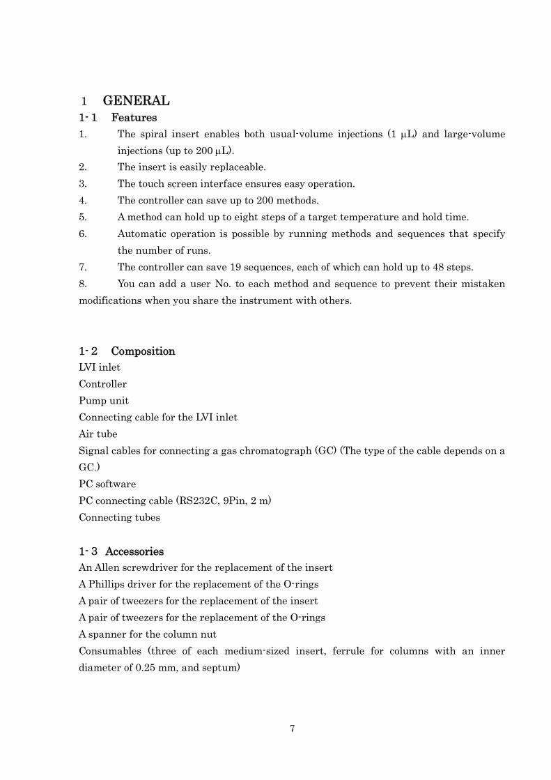
1-3 Accessories
An Allen screwdriver for the replacement of the insert
A Phillips driver for the replacement of the O-rings
A pair of tweezers for the replacement of the insert
A pair of tweezers for the replacement of the O-rings
A spanner for the column nut
Consumables (three of each medium-sized insert, ferrule for columns with an inner
diameter of 0.25 mm, and septum)

8
1-4 Optional Items
Solvent vent (optional)
Electronic pneumatic control (EPC) module for programmable temperature vaporization
(PTV) injections (a flow controller for PTV on Agilent GCs)
Advanced flow controller (AFC) (a flow controller for Shimadzu GCs)
9
2 SPECIFICATIONS
2-1 Inlet
Injection methods Large volume injection, derivatization injection, split
injection, splitless injection, cold split injection, cold
splitless injection, on-column injection
Heating method Air heating
2-2 Controller
Temperature control range 40 C to 300 C (with the ambient temperature: 25 C,
column oven temperature: 50 C)
Maximum heating rate 150 C per minute
Display and operation 128 × 64 dot LCD touch screen interface
Size 100 mm (W) 300 mm (D) 200 mm (H)
Weight 3.3 kg
Line voltage 100 VAC, 50/60 Hz
Power consumption 120 VA
2-3 Pump Unit
Size 160 mm (W) 130 mm (D) 115 mm (H)
Weight 2.5kg
Line voltage Supplied from the controller
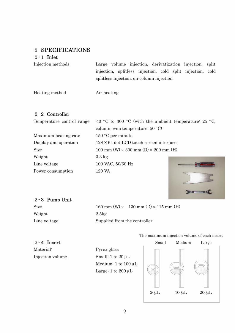
2-4 Insert
Material: Pyrex glass
Injection volume Small: 1 to 20 L
Medium: 1 to 100 L
Large: 1 to 200 L
20L 100L 200L
The maximum injection volume of each insert
Small Medium Large
10
3 OVERVIEW OF PARTS
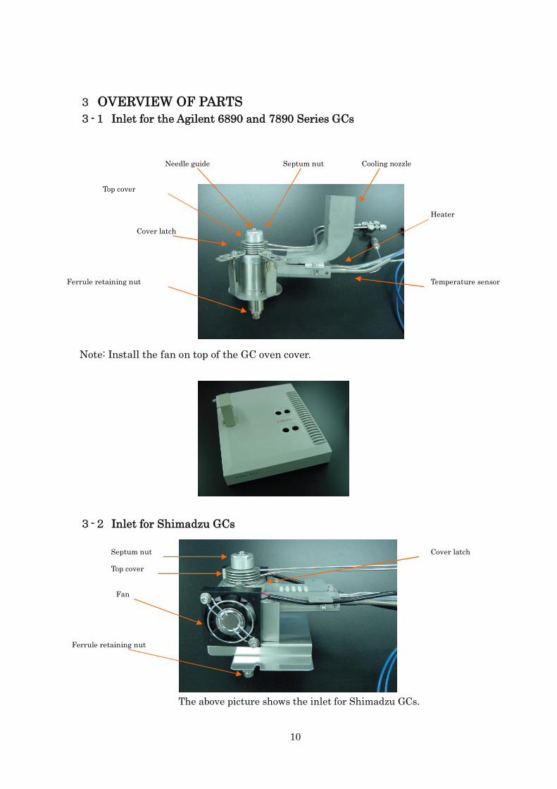
3-1 Inlet for the Agilent 6890 and 7890 Series GCs
Note: Install the fan on top of the GC oven cover.
3-2 Inlet for Shimadzu GCs
Ferrule retaining nut
Top cover
Septum nut
Cover latch
Cooling nozzle
Temperature sensor
Heater
Needle guide
Ferrule retaining nut
Top cover
Fan
Septum nut Cover latch
The above picture shows the inlet for Shimadzu GCs.
11
Air tube connector
LGI link (optional)
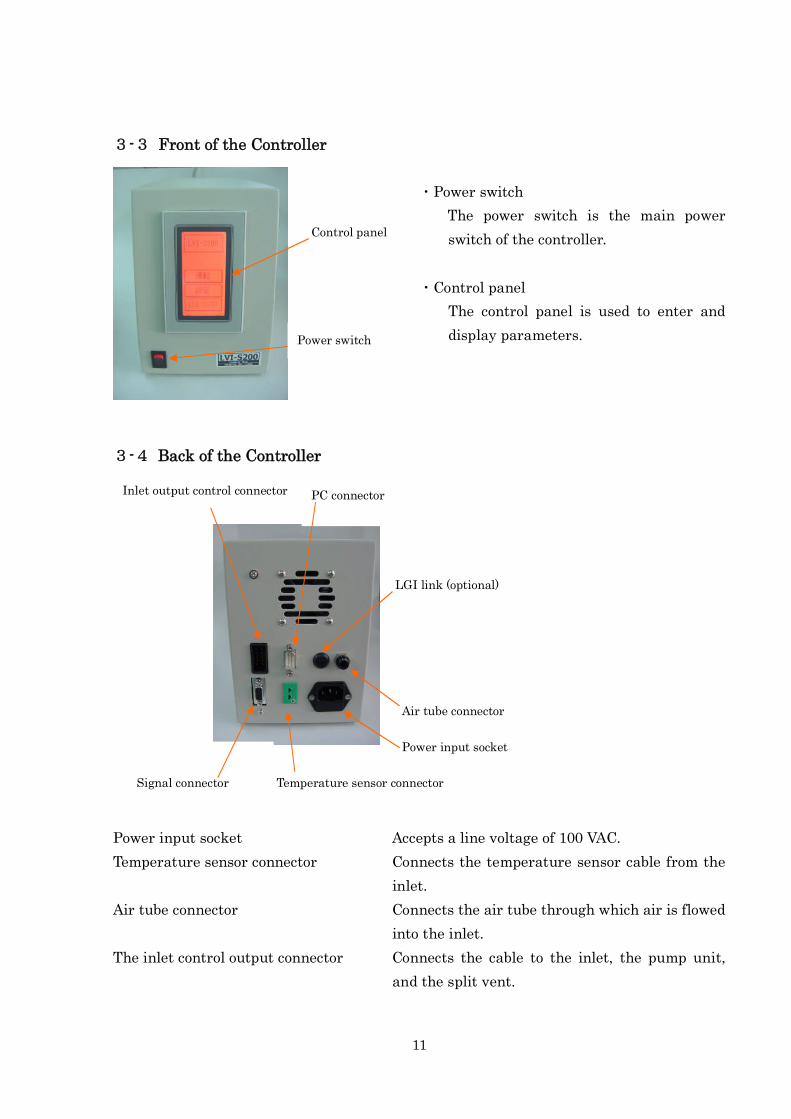
3-3 Front of the Controller
・Power switch
The power switch is the main power
switch of the controller.
・Control panel
The control panel is used to enter and
display parameters.
3-4 Back of the Controller
Power input socket Accepts a line voltage of 100 VAC.
Temperature sensor connector Connects the temperature sensor cable from the
inlet.
Air tube connector Connects the air tube through which air is flowed
into the inlet.
The inlet control output connector Connects the cable to the inlet, the pump unit,
and the split vent.
Power switch
Control panel
Temperature sensor connector
Power input socket
Inlet output control connector
Signal connector
PC connector
12
Signal connector Connects a gas chromatograph.
PC connector Connects a PC.
LGI link Connects and controls the LGI-S100 (optional).
13
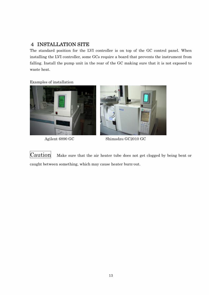
4 INSTALLATION SITEThe standard position for the LVI controller is on top of the GC control panel. When
installing the LVI controller, some GCs require a board that prevents the instrument from
falling. Install the pump unit in the rear of the GC making sure that it is not exposed to
waste heat.
Examples of installation
Agilent 6890 GC Shimadzu GC2010 GC
Caution Make sure that the air heater tube does not get clogged by being bent or
caught between something, which may cause heater burn-out.
14
5 INSTALLING LVI ON GCSee other reference manual.
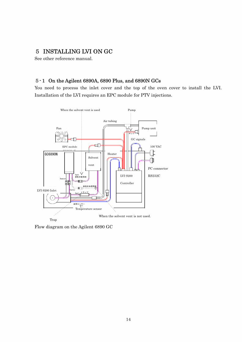
5-1 On the Agilent 6890A, 6890 Plus, and 6890N GCs
You need to process the inlet cover and the top of the oven cover to install the LVI.
Installation of the LVI requires an EPC module for PTV injections.
GC6890N
冷却ファン
LVI-S200
注入口
トラップ
EPCモジュール
溶媒排気弁
ポンプユニット
LVI-S200コントローラ
GC信号
AC100V
PC接続RS232C
排気弁使用時
排気弁未使用時
ヒーター
温度センサー
エアー配管
ポンプ
Septum
Carrier
Sprit
Sprit
Flow diagram on the Agilent 6890 GC
Fan
Air tubing
Pump unit
100 VAC
PC connector
RS232CLVI-S200
Controller
EPC module
LVI-S200 Inlet
Pump
GC signals
Temperature sensor
Heater
Solvent
vent
When the solvent vent is used
TrapWhen the solvent vent is not used.
15
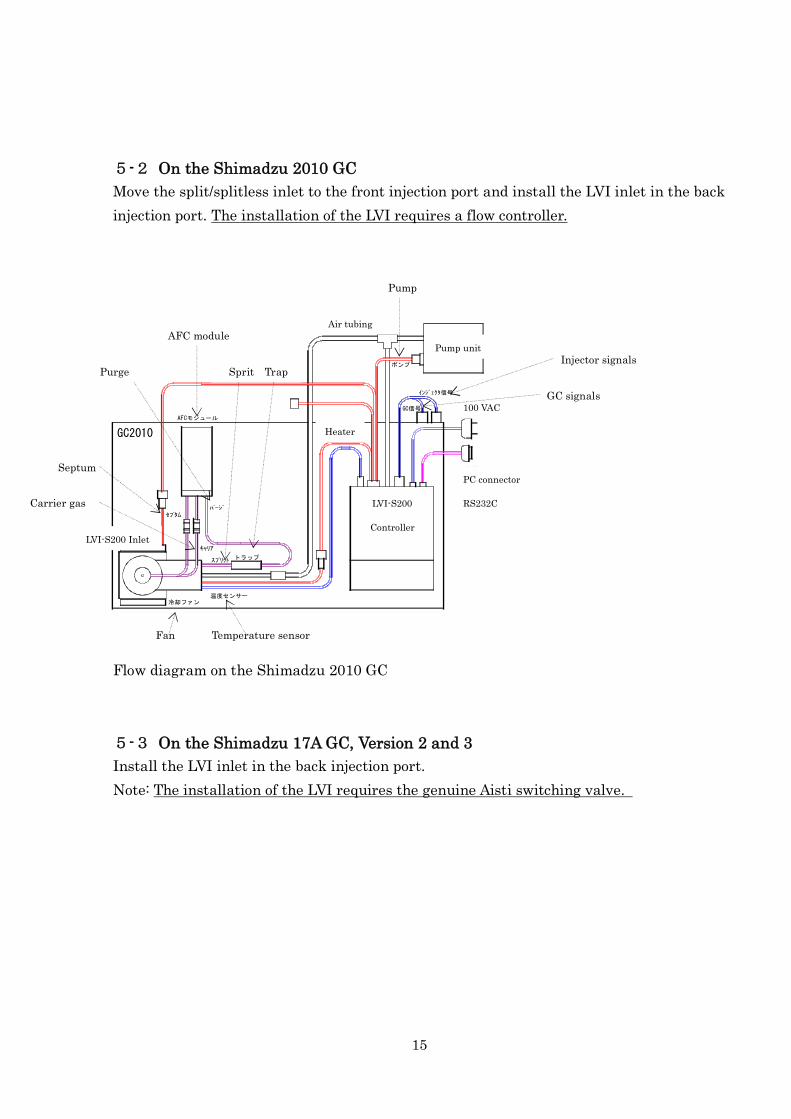
5-2 On the Shimadzu 2010 GC
Move the split/splitless inlet to the front injection port and install the LVI inlet in the back
injection port. The installation of the LVI requires a flow controller.
GC2010
冷却ファン
LVI-S200
注入口
トラップ
AFCモジュール
ポンプユニット
LVI-S200コントローラ
GC信号AC100V
PC接続RS232C
ヒーター
温度センサー
エアー配管
ポンプ
セプタム
キャリア
スプリット
パージ
インジェクタ信号
Flow diagram on the Shimadzu 2010 GC
5-3 On the Shimadzu 17A GC, Version 2 and 3
Install the LVI inlet in the back injection port.
Note: The installation of the LVI requires the genuine Aisti switching valve.
Pump unit
100 VAC
PC connector
RS232CLVI-S200
Controller
GC signals
Pump
Air tubing
Heater
LVI-S200 Inlet
Fan Temperature sensor
Injector signals
Septum
Purge Sprit Trap
Carrier gas
AFC module
16
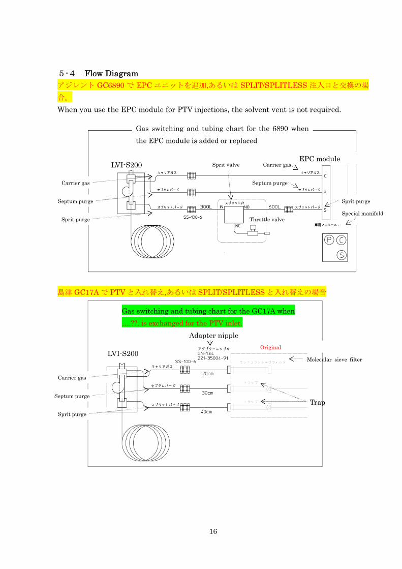
5-4 Flow Diagram
アジレント GC6890 で EPC ユニットを追加,あるいは SPLIT/SPLITLESS 注入口と交換の場
合。
When you use the EPC module for PTV injections, the solvent vent is not required.
島津 GC17A で PTV と入れ替え,あるいは SPLIT/SPLITLESS と入れ替えの場合
Gas switching and tubing chart for the 6890 when
the EPC module is added or replaced
EPC moduleLVI-S200
Carrier gas
Sprit purge
Septum purge
Carrier gas
Sprit purge
Septum purge
Carrier gas
Sprit purge
Septum purge
Throttle valve
Sprit valve
Special manifold
Gas switching and tubing chart for the GC17A when
….??. is exchanged for the PTV inlet.
Adapter nipple
Original
Molecular sieve filter
Trap
LVI-S200
17
5-5 Connecting the Controller
Enter the model of your GC on the GC model setting display of the LVI controller before
connecting them with each other.
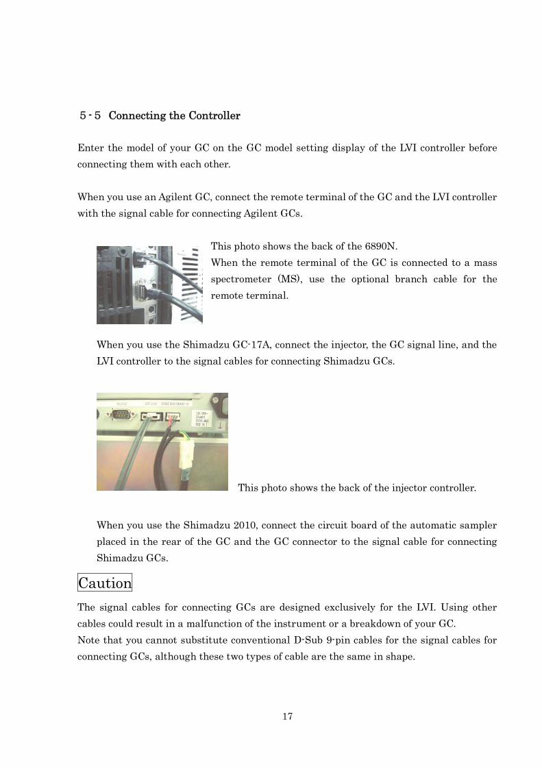
When you use an Agilent GC, connect the remote terminal of the GC and the LVI controller
with the signal cable for connecting Agilent GCs.
This photo shows the back of the 6890N.
When the remote terminal of the GC is connected to a mass
spectrometer (MS), use the optional branch cable for the
remote terminal.
When you use the Shimadzu GC-17A, connect the injector, the GC signal line, and the
LVI controller to the signal cables for connecting Shimadzu GCs.
This photo shows the back of the injector controller.
When you use the Shimadzu 2010, connect the circuit board of the automatic sampler
placed in the rear of the GC and the GC connector to the signal cable for connecting
Shimadzu GCs.
Caution
The signal cables for connecting GCs are designed exclusively for the LVI. Using other
cables could result in a malfunction of the instrument or a breakdown of your GC.
Note that you cannot substitute conventional D-Sub 9-pin cables for the signal cables for
connecting GCs, although these two types of cable are the same in shape.
18
Signals from GCs from different manufacturers.
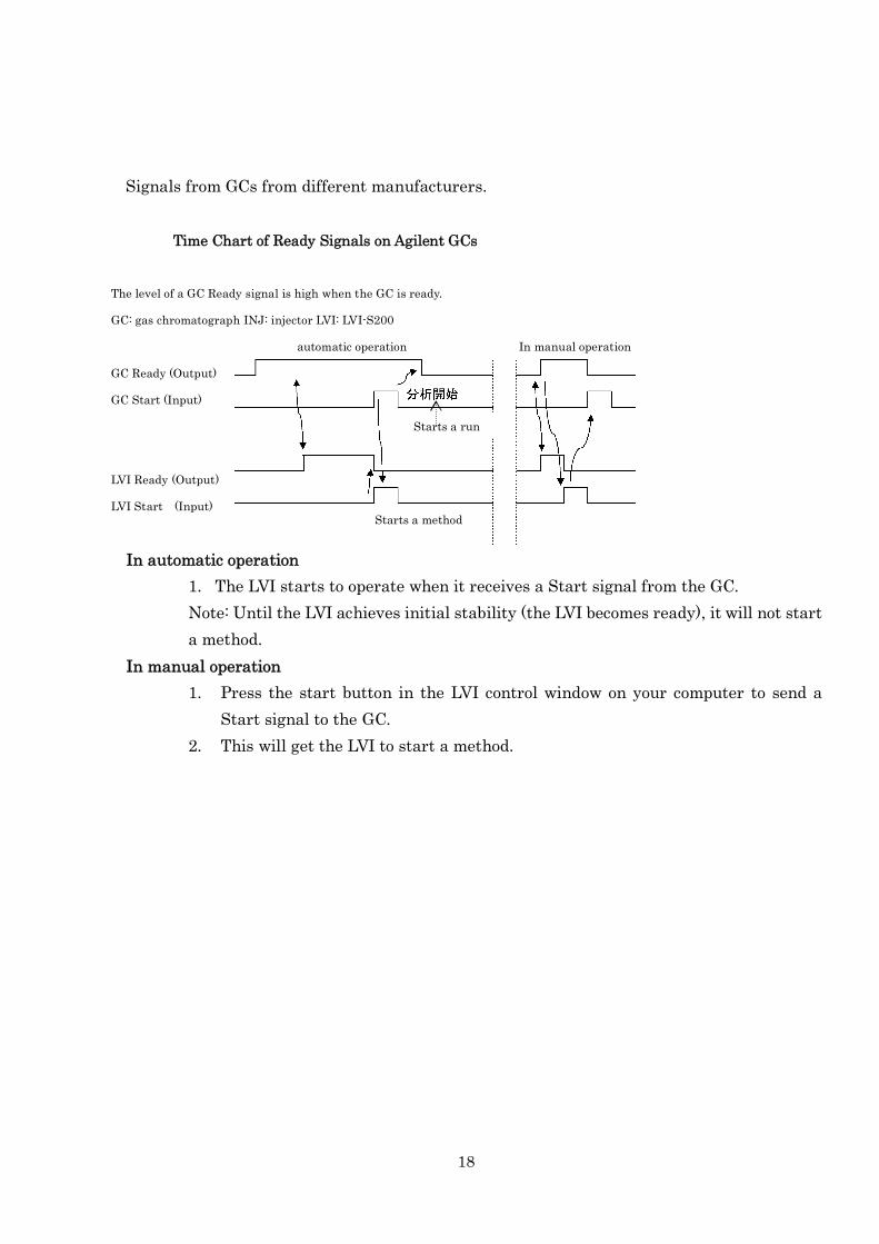
Time Chart of Ready Signals on Agilent GCs
The level of a GC Ready signal is high when the GC is ready.
GC: gas chromatograph INJ: injector LVI: LVI-S200
automatic operation In manual operation
GC Ready (Output)
GC Start (Input)
LVI Ready (Output)
LVI Start (Input)
Starts a run
Starts a method
In automatic operation
1. The LVI starts to operate when it receives a Start signal from the GC.
Note: Until the LVI achieves initial stability (the LVI becomes ready), it will not start
a method.
In manual operation
1. Press the start button in the LVI control window on your computer to send a
Start signal to the GC.
2. This will get the LVI to start a method.
19
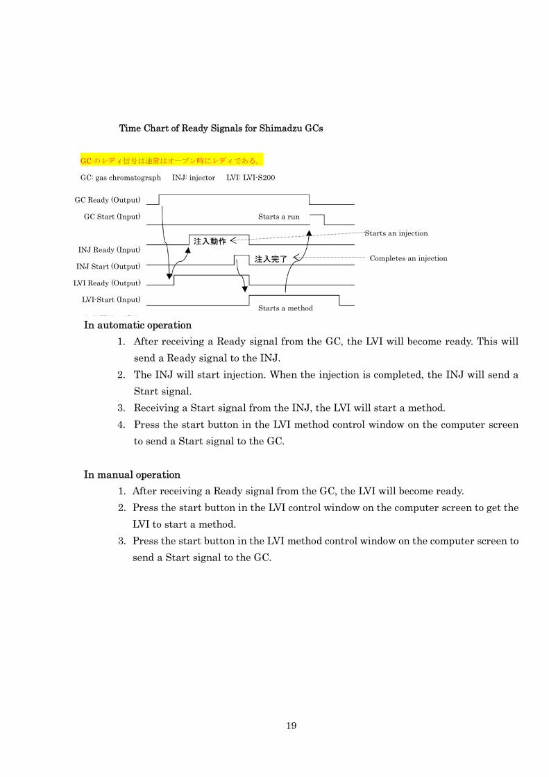
Time Chart of Ready Signals for Shimadzu GCs
GC のレディ信号は通常はオープン時にレディである。
GC: gas chromatograph INJ: injector LVI: LVI-S200
GC Ready (Output)
GC Start (Input)
INJ Ready (Input)
INJ Start (Output)
LVI Ready (Output)
LVI-Start (Input)Starts a method
Completes an injection
Starts a run
Starts an injection
In automatic operation
1. After receiving a Ready signal from the GC, the LVI will become ready. This will
send a Ready signal to the INJ.
2. The INJ will start injection. When the injection is completed, the INJ will send a
Start signal.
3. Receiving a Start signal from the INJ, the LVI will start a method.
4. Press the start button in the LVI method control window on the computer screen
to send a Start signal to the GC.
In manual operation
1. After receiving a Ready signal from the GC, the LVI will become ready.
2. Press the start button in the LVI control window on the computer screen to get the
LVI to start a method.
3. Press the start button in the LVI method control window on the computer screen to
send a Start signal to the GC.
20
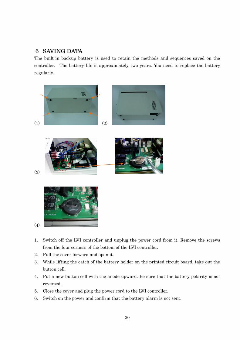
6 SAVING DATAThe built-in backup battery is used to retain the methods and sequences saved on the
controller. The battery life is approximately two years. You need to replace the battery
regularly.
(1) (2)
(3)
(4)
1. Switch off the LVI controller and unplug the power cord from it. Remove the screws
from the four corners of the bottom of the LVI controller.
2. Pull the cover forward and open it.
3. While lifting the catch of the battery holder on the printed circuit board, take out the
button cell.
4. Put a new button cell with the anode upward. Be sure that the battery polarity is not
reversed.
5. Close the cover and plug the power cord to the LVI controller.
6. Switch on the power and confirm that the battery alarm is not sent.

21
Replacement battery] Part number LB-2010-014, BR2020 from Panasonic Corp. 1,500
yen
Install the LVI controller in the reverse order of removal. Connect the cables and the tube
to the LVI controller. Securely fix the LVI controller onto the rod that is placed to prevent
the instrument from falling off. (After fitting the LVI controller onto the rod, slightly push
the controller backwards to fix it.)
22
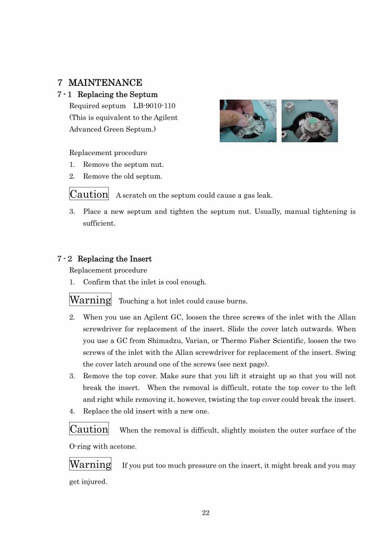
7 MAINTENANCE7-1 Replacing the Septum
Required septum LB-9010-110
(This is equivalent to the Agilent
Advanced Green Septum.)
Replacement procedure
1. Remove the septum nut.
2. Remove the old septum.
Caution A scratch on the septum could cause a gas leak.
3. Place a new septum and tighten the septum nut. Usually, manual tightening is
sufficient.
7-2 Replacing the Insert
Replacement procedure
1. Confirm that the inlet is cool enough.
Warning Touching a hot inlet could cause burns.
2. When you use an Agilent GC, loosen the three screws of the inlet with the Allan
screwdriver for replacement of the insert. Slide the cover latch outwards. When
you use a GC from Shimadzu, Varian, or Thermo Fisher Scientific, loosen the two
screws of the inlet with the Allan screwdriver for replacement of the insert. Swing
the cover latch around one of the screws (see next page).
3. Remove the top cover. Make sure that you lift it straight up so that you will not
break the insert. When the removal is difficult, rotate the top cover to the left
and right while removing it, however, twisting the top cover could break the insert.
4. Replace the old insert with a new one.
Caution When the removal is difficult, slightly moisten the outer surface of the
O-ring with acetone.
Warning If you put too much pressure on the insert, it might break and you may
get injured.
23
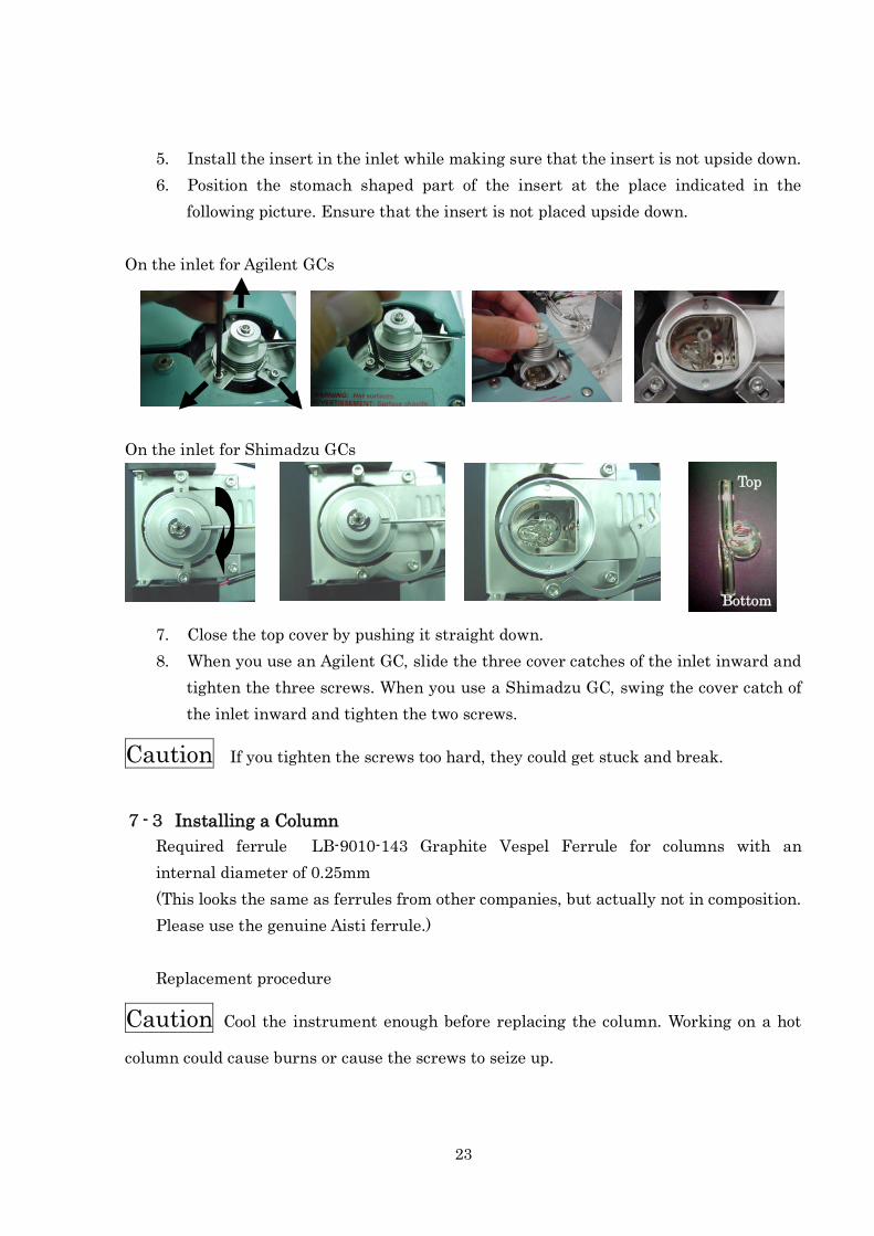
5. Install the insert in the inlet while making sure that the insert is not upside down.
6. Position the stomach shaped part of the insert at the place indicated in the
following picture. Ensure that the insert is not placed upside down.
On the inlet for Agilent GCs
On the inlet for Shimadzu GCs
7. Close the top cover by pushing it straight down.
8. When you use an Agilent GC, slide the three cover catches of the inlet inward and
tighten the three screws. When you use a Shimadzu GC, swing the cover catch of
the inlet inward and tighten the two screws.
Caution If you tighten the screws too hard, they could get stuck and break.
7-3 Installing a Column
Required ferrule LB-9010-143 Graphite Vespel Ferrule for columns with an
internal diameter of 0.25mm
(This looks the same as ferrules from other companies, but actually not in composition.
Please use the genuine Aisti ferrule.)
Replacement procedure
Caution Cool the instrument enough before replacing the column. Working on a hot
column could cause burns or cause the screws to seize up.
Bottom
Top
24
1. Loosen the column nut installed to the inlet inside the oven.
2. Thread a column through the column nut first and then the ferrule. Cut a tip of the
column.
3. Insert the ferrule, the column nut, and the column into the column port of the inlet
and temporarily tighten the column nut. Push the column until it reaches the
inner surface of the insert. Then, withdraw it 2 to 3 mm. (Set the column to project
approximately 30 mm from the end of the ferrule.)
4. Tighten the column nut with the spanner for the column nut.
5. Pull the column to confirm that it is secure.
The column nut for the LVI is compatible with Agilent split/splitless inlets. Note that a
length of the column to be projected from the end of the ferule is different on Agilent inlets.
7-4 Replacing the O-rings
Replacement procedure
Caution When the removal is difficult, slightly moisten the outer surface of the
O-ring with acetone.
Caution A scratch on the O-ring could cause a gas leak.
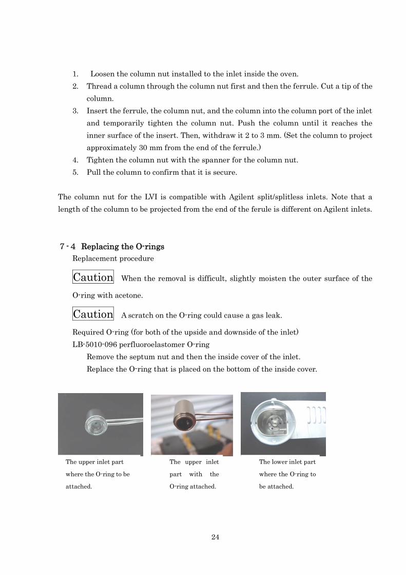
Required O-ring (for both of the upside and downside of the inlet)
LB-5010-096 perfluoroelastomer O-ring
Remove the septum nut and then the inside cover of the inlet.
Replace the O-ring that is placed on the bottom of the inside cover.
The upper inlet part
where the O-ring to be
attached.
The upper inlet
part with the
O-ring attached.
The lower inlet part
where the O-ring to
be attached.
25
O-ring placed on the lower inlet part Perfluoroelastomer O-ring AS568A-008
Loosen the three screws in the same way of the replacement of the O-ring for the
upper inlet part. Turn the O-ring catch clockwise to the position where the heads
of the three screws do not interference with the removal of the O-ring catch.
Remove the O-ring catch and replace the old O-ring with a new one.
When you remove the O-ring catch, use a pair of tweezers.
Caution If the removal is difficult, slightly moisten the outer surface of the O-ring
with acetone.
Caution Since the screws are small, do not tighten them too hard. Do not remove the
screws. Removing the screws could result in damage to their threads when they are
retightened. A scratch on the O-rings and around the hole for delivering gases could cause
a gas leak.
7-5 Replacing the Heater
The air heater is a consumable.
Replacement procedure for the inlet for Agilent GCs
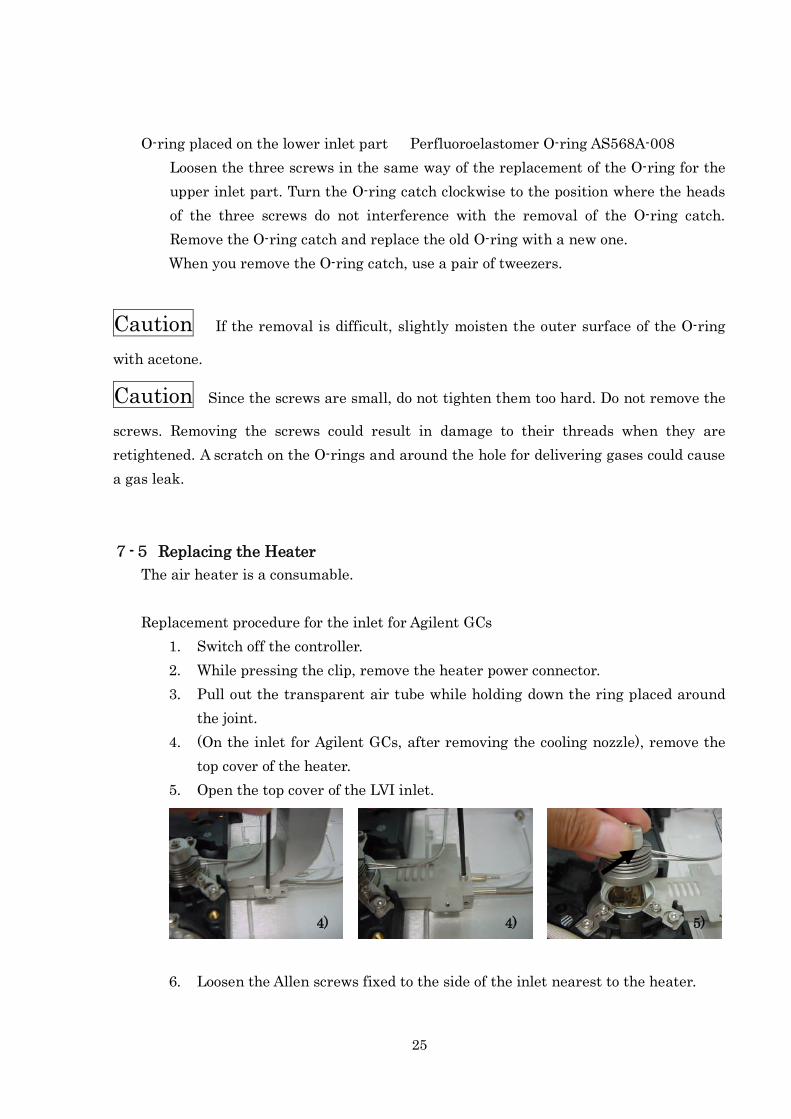
1. Switch off the controller.
2. While pressing the clip, remove the heater power connector.
3. Pull out the transparent air tube while holding down the ring placed around
the joint.
4. (On the inlet for Agilent GCs, after removing the cooling nozzle), remove the
top cover of the heater.
5. Open the top cover of the LVI inlet.
6. Loosen the Allen screws fixed to the side of the inlet nearest to the heater.
4) 4) 5)
26
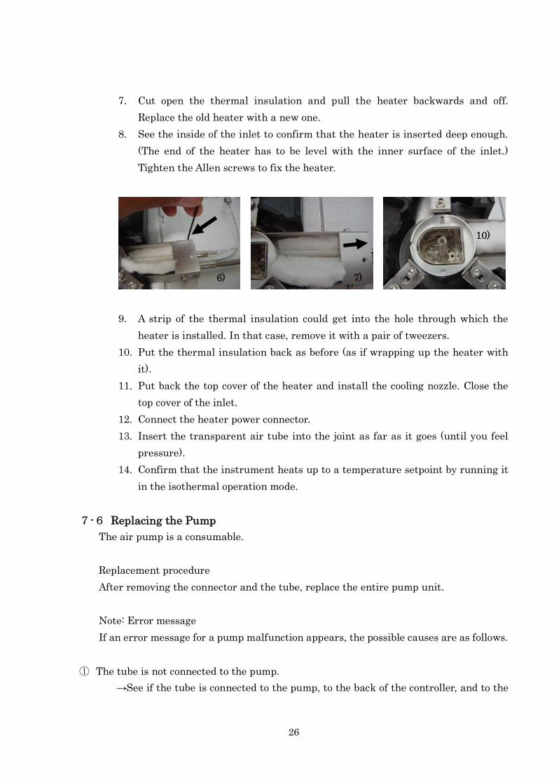
7. Cut open the thermal insulation and pull the heater backwards and off.
Replace the old heater with a new one.
8. See the inside of the inlet to confirm that the heater is inserted deep enough.
(The end of the heater has to be level with the inner surface of the inlet.)
Tighten the Allen screws to fix the heater.
9. A strip of the thermal insulation could get into the hole through which the
heater is installed. In that case, remove it with a pair of tweezers.
10. Put the thermal insulation back as before (as if wrapping up the heater with
it).
11. Put back the top cover of the heater and install the cooling nozzle. Close the
top cover of the inlet.
12. Connect the heater power connector.
13. Insert the transparent air tube into the joint as far as it goes (until you feel
pressure).
14. Confirm that the instrument heats up to a temperature setpoint by running it
in the isothermal operation mode.
7-6 Replacing the Pump
The air pump is a consumable.
Replacement procedure
After removing the connector and the tube, replace the entire pump unit.
Note: Error message
If an error message for a pump malfunction appears, the possible causes are as follows.
① The tube is not connected to the pump.
→See if the tube is connected to the pump, to the back of the controller, and to the
6) 7)
10)
27
heater.
② The built-in filter of the pump is clogged, so the pump does not have enough suction
and the air flow is insufficient.
→ Remove the filter by following the instructions below and see how the instrument
works without the filter. If it works well, the filter could be clogged. Replace the
filter.
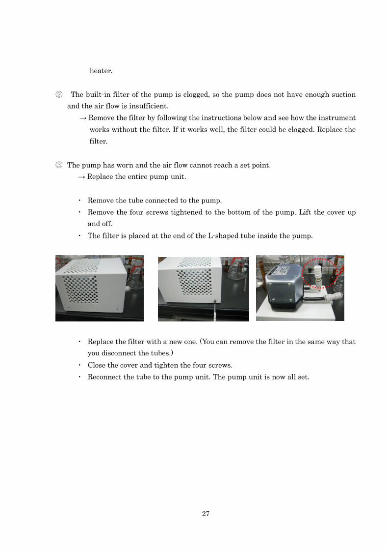
③ The pump has worn and the air flow cannot reach a set point.
→ Replace the entire pump unit.
・ Remove the tube connected to the pump.
・ Remove the four screws tightened to the bottom of the pump. Lift the cover up
and off.
・ The filter is placed at the end of the L-shaped tube inside the pump.
・ Replace the filter with a new one. (You can remove the filter in the same way that
you disconnect the tubes.)
・ Close the cover and tighten the four screws.
・ Reconnect the tube to the pump unit. The pump unit is now all set.
28
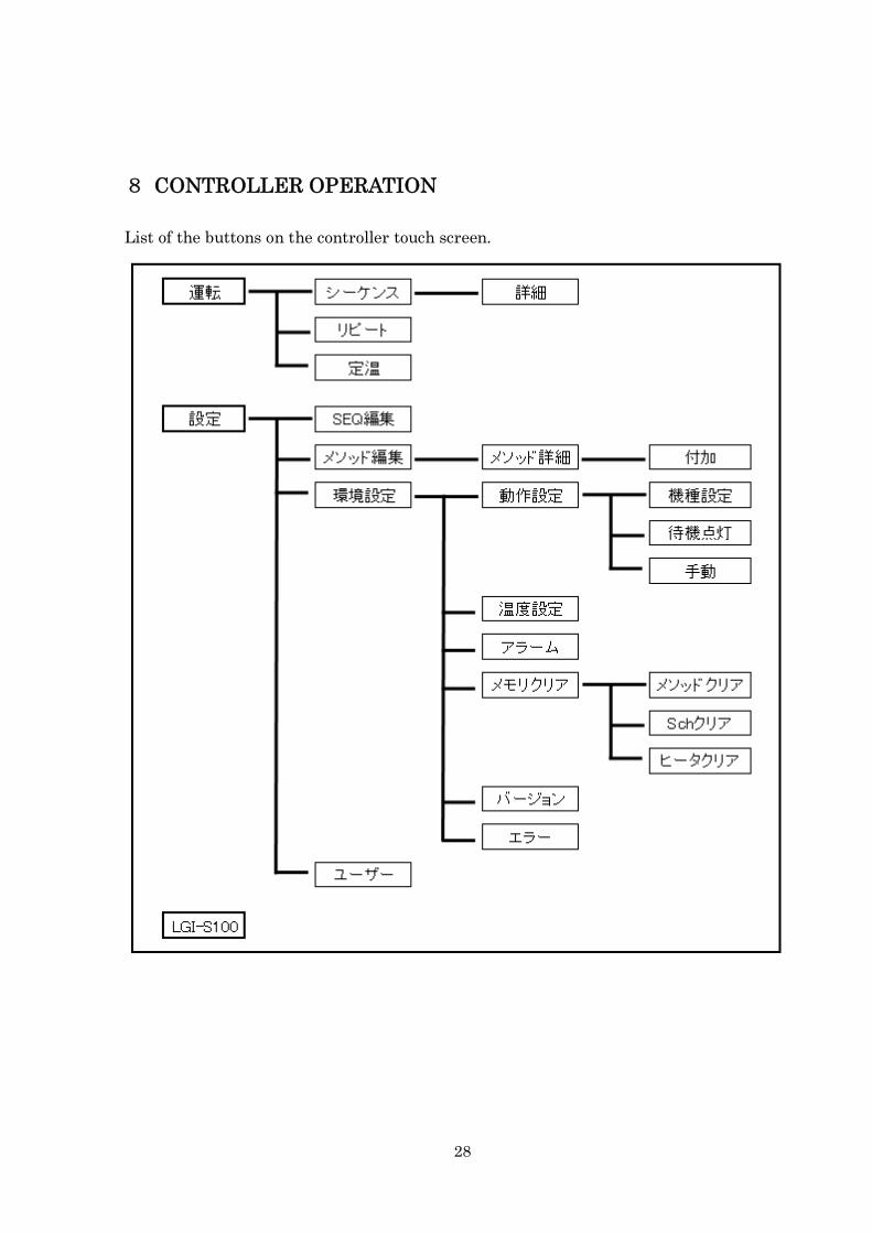
8 CONTROLLER OPERATION
List of the buttons on the controller touch screen.
29
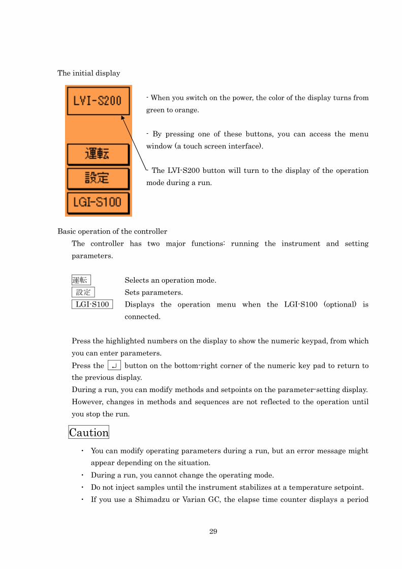
The initial display
- When you switch on the power, the color of the display turns from
green to orange.
- By pressing one of these buttons, you can access the menu
window (a touch screen interface).
- The LVI-S200 button will turn to the display of the operation
mode during a run.
Basic operation of the controller
The controller has two major functions: running the instrument and setting
parameters.
運転 Selects an operation mode.
設定 Sets parameters.
LGI-S100 Displays the operation menu when the LGI-S100 (optional) is
connected.
Press the highlighted numbers on the display to show the numeric keypad, from which
you can enter parameters.
Press the button on the bottom-right corner of the numeric key pad to return to
the previous display.
During a run, you can modify methods and setpoints on the parameter-setting display.
However, changes in methods and sequences are not reflected to the operation until
you stop the run.
Caution
・ You can modify operating parameters during a run, but an error message might
appear depending on the situation.
・ During a run, you cannot change the operating mode.
・ Do not inject samples until the instrument stabilizes at a temperature setpoint.
・ If you use a Shimadzu or Varian GC, the elapse time counter displays a period
30
that has passed since the LVI sent a Start signal to the GC. If you use an Agilent
GC, it displays a period that has passed since the LVI received a Start signal
from the GC.
・ If the inlet is hot, stop a run without turning off the power. This will cool down
the inlet more quickly by allowing the fan to assist cooling.
31
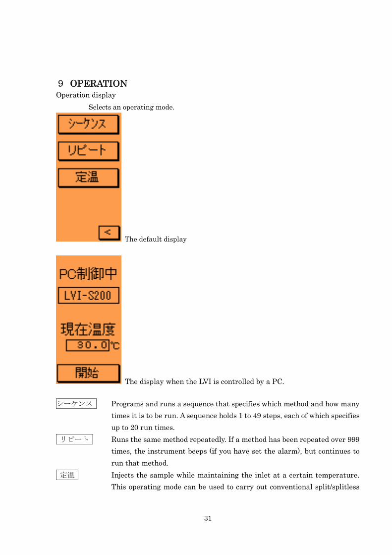
9 OPERATIONOperation display
Selects an operating mode.
The default display
The display when the LVI is controlled by a PC.
シーケンス Programs and runs a sequence that specifies which method and how many
times it is to be run. A sequence holds 1 to 49 steps, each of which specifies
up to 20 run times.
リピート Runs the same method repeatedly. If a method has been repeated over 999
times, the instrument beeps (if you have set the alarm), but continues to
run that method.
定温 Injects the sample while maintaining the inlet at a certain temperature.
This operating mode can be used to carry out conventional split/splitless
32
injections.
開始 Starts manual operation.
Caution
・ The LVI does not become ready until the GC is ready.
・ Create a GC method that allows the LVI to re-stabilize sooner than the GC after
the end of the proceeding method.
・ While the LVI is controlled by a PC, the buttons on the touch screen are
unavailable except for the開始 button. If you want to control the LVI from the touch screen,
exit the LVI-S200 software.
33
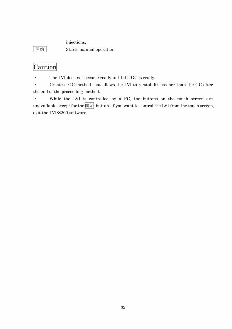
9-1 Isothermal Operation
Display
Function
The isothermal operation mode is used to perform conventional split/splitless
injections repeatedly while maintaining the instrument at a certain temperature.
The color of the display turns from orange to green when the instrument stabilizes at a
temperature setpoint by the temperature controlling function.
After each injection, the elapse time counter will be reset.
Operation
Set the target temperature and press the 定温運転 button to start the temperature
controlling operation.
Press the 定温運転 button again to stop the run and cool the instrument to a
temperature setpoint.
If you want to start manual operation, press the 開始 button to send a Start signal to
the GC.
When you change the temperature setpoint, the color of the display will turn to green after
the instrument has re-stabilized.
Caution
・ You can change the temperature setpoint during a run. In this situation, do not
inject samples until the instrument stabilizes at the changed setpoint.
・ The valid range of the temperature of the LVI inlet is from 40 C to 300 C.

34
However, note that the instrument might not stabilize at 40 C depending on the GC oven
temperature. In this situation, lower the GC oven temperature.
・ Have a longer interval between injections than the stabilization time.
35
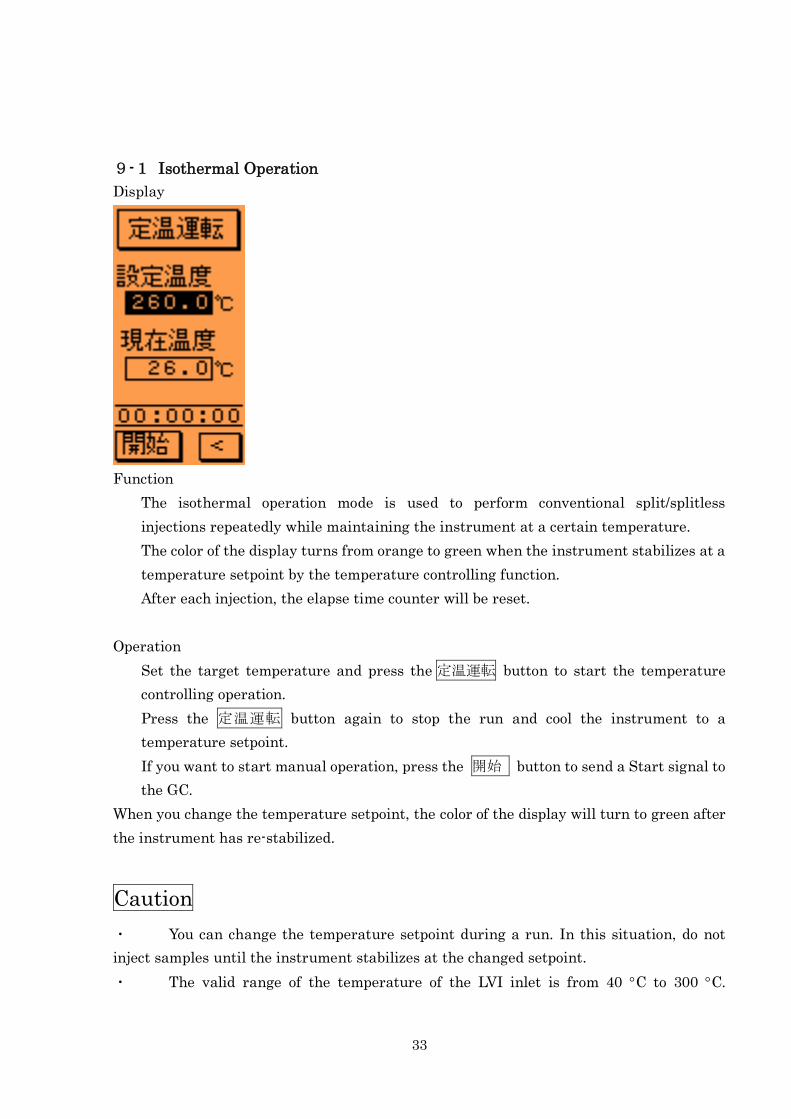
9-2 Repeat Operation
Display
Function
The repeat operation mode is used to run one method repeatedly.
The counter that displays the number of runs will be reset at the start of each new run.
If you want to modify a temperature setpoint for each sample or stop the run after the
specified number of samples are run, create an appropriate method and run the
instrument in the sequence operation mode.
Operation
Select a method No.
Press the リピート運転 button. The display will turn from 停止中 to 準備中
When the instrument stabilizes at the temperature setpoint, the display will turn to
待機中. And the color of the display will turn to green.
Once receiving a Start signal, the LVI starts running a method. The display will turn
to 運転中.
When the method is completed, the display will turn to 冷却中.
If you want to change the method, stop the running method and change the method
No.
If you want to start the manual operation, press the 開始 button to start a method.
Press the リピート停止 button to stop a run.
Caution
You cannot change the method No. during a run. (If a method has been repeated over 999

36
times, the instrument beeps and resets the counter for the number of runs, but continues
to run the method.)
If you select an undefined method, the instrument will not start running.
37
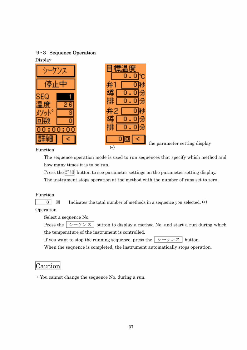
9-3 Sequence Operation
Display
the parameter setting display
Function
The sequence operation mode is used to run sequences that specify which method and
how many times it is to be run.
Press the 詳細 button to see parameter settings on the parameter setting display.
The instrument stops operation at the method with the number of runs set to zero.
Function
0 回 Indicates the total number of methods in a sequence you selected. ()
Operation
Select a sequence No.
Press the シーケンス button to display a method No. and start a run during which
the temperature of the instrument is controlled.
If you want to stop the running sequence, press the シーケンス button.
When the sequence is completed, the instrument automatically stops operation.
Caution
・You cannot change the sequence No. during a run.
()
38
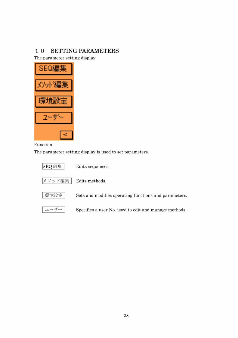
10 SETTING PARAMETERSThe parameter setting display
Function
The parameter setting display is used to set parameters.
SEQ 編集 Edits sequences.
メソッド編集 Edits methods.
環境設定 Sets and modifies operating functions and parameters.
ユーザー Specifies a user No. used to edit and manage methods.
39
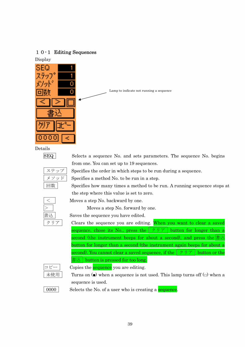
10-1 Editing Sequences
Display
Details
SEQ Selects a sequence No. and sets parameters. The sequence No. begins
from one. You can set up to 19 sequences.
ステップ Specifies the order in which steps to be run during a sequence.
メソッド Specifies a method No. to be run in a step.
回数 Specifies how many times a method to be run. A running sequence stops at
the step where this value is set to zero.
< Moves a step No. backward by one.
> Moves a step No. forward by one.
書込 Saves the sequence you have edited.
クリア Clears the sequence you are editing. When you want to clear a saved
sequence, chose its No., press the クリア button for longer than a
second (the instrument beeps for about a second), and press the 書込
button for longer than a second (the instrument again beeps for about a
second). You cannot clear a saved sequence, if the クリア button or the
書込 button is pressed for too long.
コピー Copies the sequence you are editing.
未使用 Turns on (■) when a sequence is not used. This lamp turns off (□) when a
sequence is used.
0000 Selects the No. of a user who is creating a sequence.
Lamp to indicate not running a sequence
40
Operation
1. Select a sequence No.
2. Confirm that the lamp for unused sequences is on, and edit the sequence.
3. Select a method No.
4. Set how many times the method to be repeated.
5. Press the > button to move the step No. forward by one.
Repeat the above procedure as many times as necessary.
When you finish parameter setting, press the 書込 button for two seconds or more.
The LVI beeps when the sequence is accepted.
Caution
If you select an undefined method, you cannot set the number of its runs.
If a number of runs has already been entered, it will be reset to zero.
You cannot edit a sequence with a different user No. . from your own
Procedure for copying sequences
Enter the sequence No. that you want to copy.
Press the コピー button once to make it concave.
Enter the sequence No. that you want to overwrite with the copied sequence.
Press the 書込 button. When the instrument beeps and the コピー button returns
to the previous shape, the copied sequence is accepted.
If you want to abort copying, press the コピー button to return it to the previous
shape.
If you copy a sequence with a different user No. from your own, the copied sequence
will be saved with your user No.
41
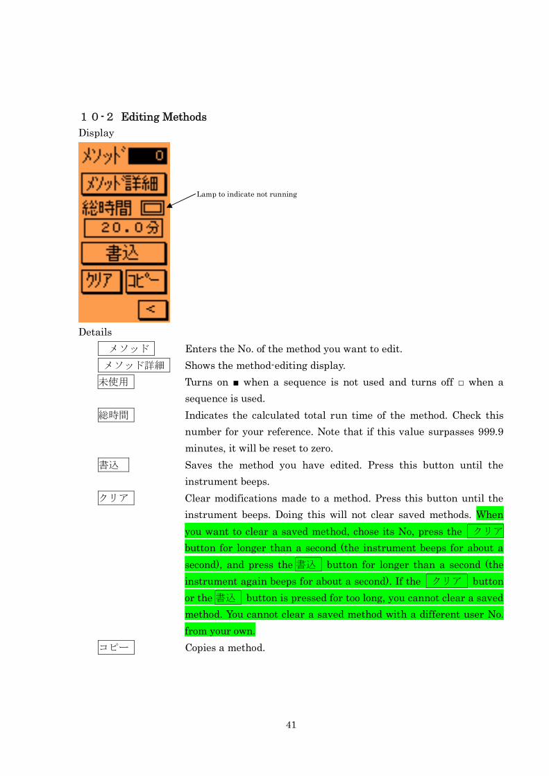
10-2 Editing Methods
Display
Details
メソッド Enters the No. of the method you want to edit.
メソッド詳細 Shows the method-editing display.
未使用 Turns on ■ when a sequence is not used and turns off □ when a
sequence is used.
総時間 Indicates the calculated total run time of the method. Check this
number for your reference. Note that if this value surpasses 999.9
minutes, it will be reset to zero.
書込 Saves the method you have edited. Press this button until the
instrument beeps.
クリア Clear modifications made to a method. Press this button until the
instrument beeps. Doing this will not clear saved methods. When
you want to clear a saved method, chose its No, press the クリア
button for longer than a second (the instrument beeps for about a
second), and press the 書込 button for longer than a second (the
instrument again beeps for about a second). If the クリア button
or the 書込 button is pressed for too long, you cannot clear a saved
method. You cannot clear a saved method with a different user No.
from your own.
コピー Copies a method.
Lamp to indicate not running
42
Procedure for copying methods
Enter the No. of a method you want to copy.
Press the コピー button once to make it concave.
Enter the No. of the method you want to overwrite with the copied method.
Press the 書込 button. When the コピー button returns to the previous look and
the instrument keeps beeping, the copied method has been accepted.
If you want to abort copying, press the コピー button to return it to the previous
look.
If you copy a method with a different user No. from your own, the copied method will
be saved with your user No.
43
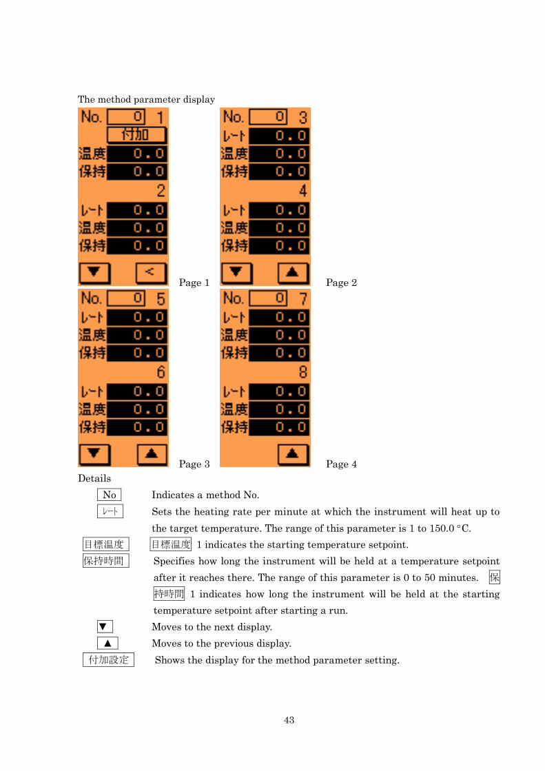
The method parameter display
Page 1 Page 2
Page 3 Page 4
Details
No Indicates a method No.
レート Sets the heating rate per minute at which the instrument will heat up to
the target temperature. The range of this parameter is 1 to 150.0 C.
目標温度 目標温度 1 indicates the starting temperature setpoint.
保持時間 Specifies how long the instrument will be held at a temperature setpoint
after it reaches there. The range of this parameter is 0 to 50 minutes. 保
持時間 1 indicates how long the instrument will be held at the starting
temperature setpoint after starting a run.
▼ Moves to the next display.
▲ Moves to the previous display.
付加設定 Shows the display for the method parameter setting.
44
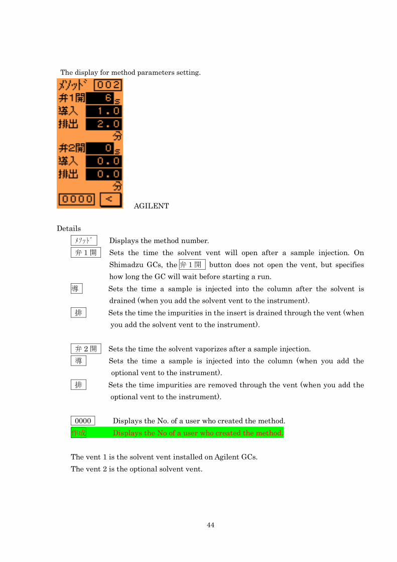
The display for method parameters setting.
AGILENT
Details
メソッド Displays the method number.
弁1開 Sets the time the solvent vent will open after a sample injection. On
Shimadzu GCs, the 弁1開 button does not open the vent, but specifies
how long the GC will wait before starting a run.
導 Sets the time a sample is injected into the column after the solvent is
drained (when you add the solvent vent to the instrument).
排 Sets the time the impurities in the insert is drained through the vent (when
you add the solvent vent to the instrument).
弁 2 開 Sets the time the solvent vaporizes after a sample injection.
導 Sets the time a sample is injected into the column (when you add the
optional vent to the instrument).
排 Sets the time impurities are removed through the vent (when you add the
optional vent to the instrument).
0000 Displays the No. of a user who created the method.
作成 Displays the No of a user who created the method.
The vent 1 is the solvent vent installed on Agilent GCs.
The vent 2 is the optional solvent vent.
45
10-3 Procedure for Creating Methods
Procedure for creating methods
1. Select the method No. that you want to load or edit. And press the メソッド詳細
button.
2. Specify the starting temperature setpoint.
3. After the step 1, set a target temperature and the time the instrument heats up. Set
the hold time, if necessary.
4. Do not set the target temperature to the same value in the prior step.
5. If you set a target temperature to a lower value than the one for the previous step,
the heating time is disregarded, but the instrument is controlled to reach a target
temperature.
6. If necessary, make additional settings on the method parameter setting display.
7. When you finish parameter setting, press the button to return to the
method-editing window.
8. Press the 書込 button until the instrument beeps to save the parameters. You can
use created methods when carrying out the repeat operation or the sequence
operation.
Note: When you modify the parameters of a running method, the modification will not
be reflected to the operation until you stop the run.
46
,
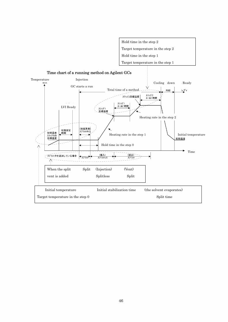
Time chart of a running method on Agilent GCs
Temperature Injection
GC starts a run
LVI Ready
R ReadyCooling down
Total time of a method
Heating rate in the step 1
Heating rate in the step 2
Initial temperature
Time
Hold time in the step 0
Hold time in the step 2
Target temperature in the step 2
Hold time in the step 1
Target temperature in the step 1
Initial temperature Initial stabilization time (the solvent evaporates)
Target temperature in the step 0 Split time
When the split Split (Injection) (Vent)
vent is added Splitless Split
47
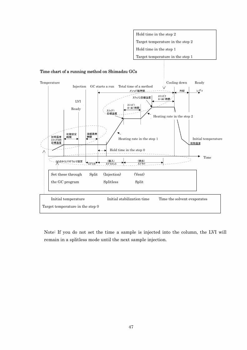
Note: If you do not set the time a sample is injected into the column, the LVI will
remain in a splitless mode until the next sample injection.
Hold time in the step 2
Target temperature in the step 2
Hold time in the step 1
Target temperature in the step 1
Total time of a methodReadyCooling down
Heating rate in the step 1
Heating rate in the step 2
Initial temperature
Time
Hold time in the step 0
Temperature
Time chart of a running method on Shimadzu GCs
Injection GC starts a run
LVI
Ready
Initial temperature Initial stabilization time Time the solvent evaporates
Target temperature in the step 0
Set these through Split (Injection) (Vent)
the GC program Splitless Split
48
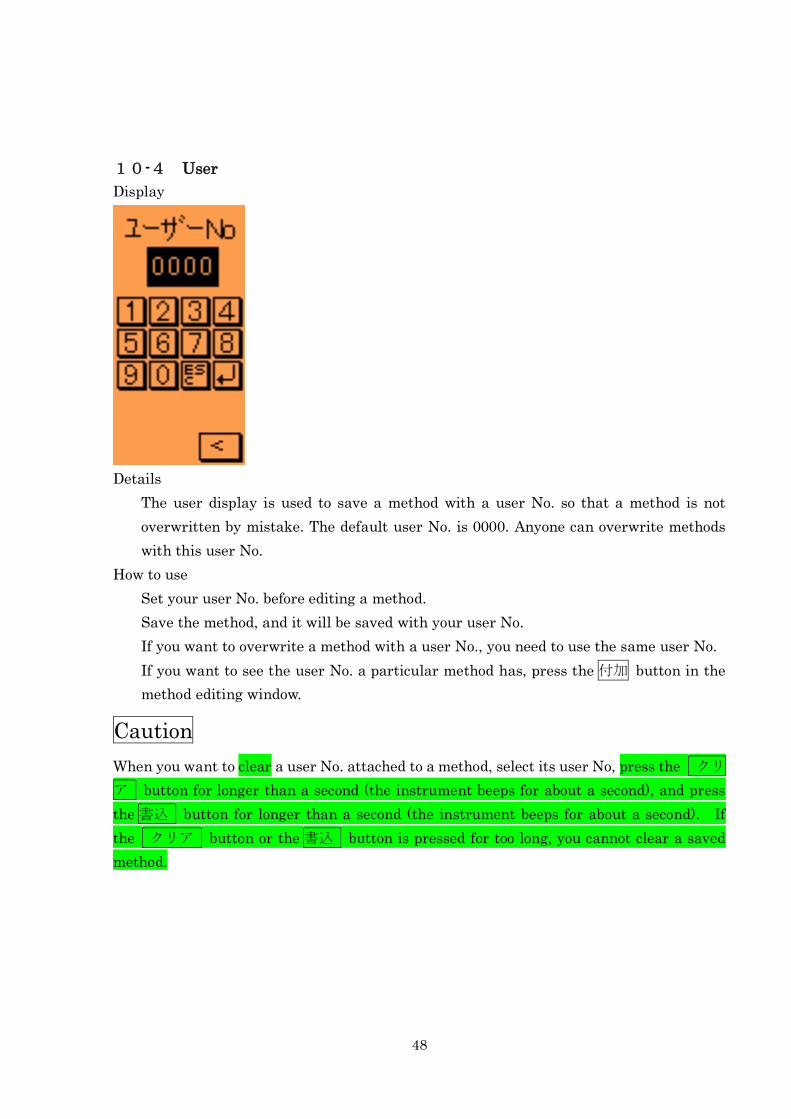
10-4 User
Display
Details
The user display is used to save a method with a user No. so that a method is not
overwritten by mistake. The default user No. is 0000. Anyone can overwrite methods
with this user No.
How to use
Set your user No. before editing a method.
Save the method, and it will be saved with your user No.
If you want to overwrite a method with a user No., you need to use the same user No.
If you want to see the user No. a particular method has, press the 付加 button in the
method editing window.
Caution
When you want to clear a user No. attached to a method, select its user No, press the クリ
ア button for longer than a second (the instrument beeps for about a second), and press
the 書込 button for longer than a second (the instrument beeps for about a second). If
the クリア button or the 書込 button is pressed for too long, you cannot clear a saved
method.
49
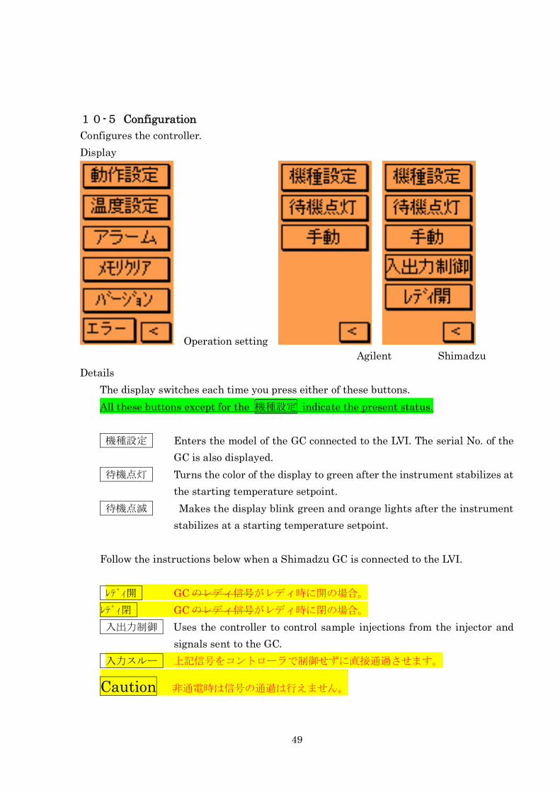
10-5 Configuration
Configures the controller.
Display
Operation setting
Agilent Shimadzu
Details
The display switches each time you press either of these buttons.
All these buttons except for the 機種設定 indicate the present status.
機種設定 Enters the model of the GC connected to the LVI. The serial No. of the
GC is also displayed.
待機点灯 Turns the color of the display to green after the instrument stabilizes at
the starting temperature setpoint.
待機点滅 Makes the display blink green and orange lights after the instrument
stabilizes at a starting temperature setpoint.
Follow the instructions below when a Shimadzu GC is connected to the LVI.
レディ開 GC のレディ信号がレディ時に開の場合。
レディ閉 GC のレディ信号がレディ時に閉の場合。
入出力制御 Uses the controller to control sample injections from the injector and
signals sent to the GC.
入力スルー 上記信号をコントローラで制御せずに直接通過させます。
Caution 非通電時は信号の通過は行えません。
50
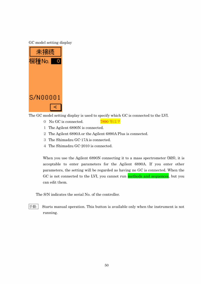
GC model setting display
The GC model setting display is used to specify which GC is connected to the LVI.
0 No GC is connected. 7890 等は?
1 The Agilent 6890N is connected.
2 The Agilent 6890A or the Agilent 6890A Plus is connected.
3 The Shimadzu GC-17A is connected.
4 The Shimadzu GC-2010 is connected.
When you use the Agilent 6890N connecting it to a mass spectrometer (MS), it is
acceptable to enter parameters for the Agilent 6890A. If you enter other
parameters, the setting will be regarded as having no GC is connected. When the
GC is not connected to the LVI, you cannot run methods and sequences, but you
can edit them.
The S/N indicates the serial No. of the controller.
手動 Starts manual operation. This button is available only when the instrument is not
running.
51
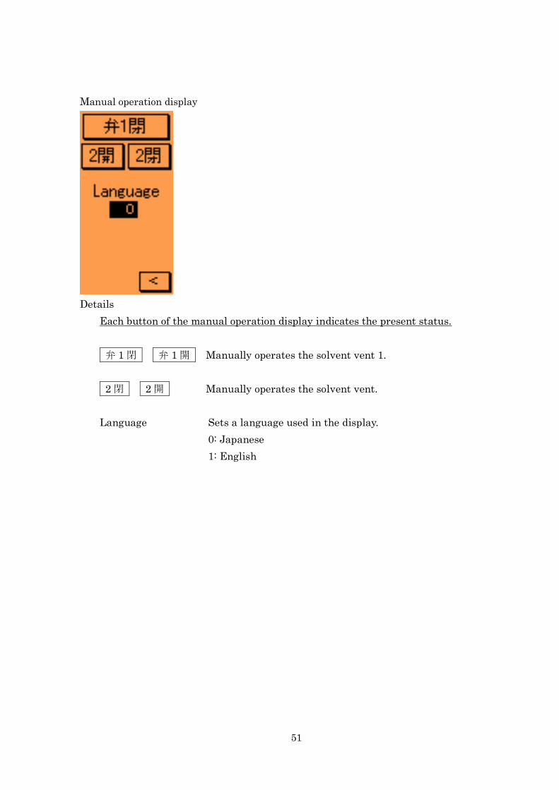
Manual operation display
Details
Each button of the manual operation display indicates the present status.
弁 1 閉 弁 1 開 Manually operates the solvent vent 1.
2 閉 2 開 Manually operates the solvent vent.
Language Sets a language used in the display.
0: Japanese
1: English
52
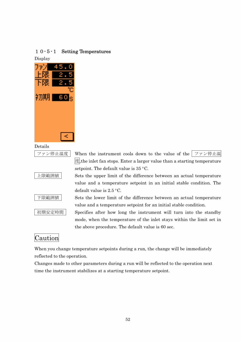
10-5-1 Setting Temperatures
Display
Details
ファン停止温度 When the instrument cools down to the value of the ファン停止温
度,the inlet fan stops. Enter a larger value than a starting temperature
setpoint. The default value is 35 C.
上限範囲値 Sets the upper limit of the difference between an actual temperature
value and a temperature setpoint in an initial stable condition. The
default value is 2.5 C.
下限範囲値 Sets the lower limit of the difference between an actual temperature
value and a temperature setpoint for an initial stable condition.
初期安定時間 Specifies after how long the instrument will turn into the standby
mode, when the temperature of the inlet stays within the limit set in
the above procedure. The default value is 60 sec.
Caution
When you change temperature setpoints during a run, the change will be immediately
reflected to the operation.
Changes made to other parameters during a run will be reflected to the operation next
time the instrument stabilizes at a starting temperature setpoint.
53
10-5-2 Version Display
Display
Details
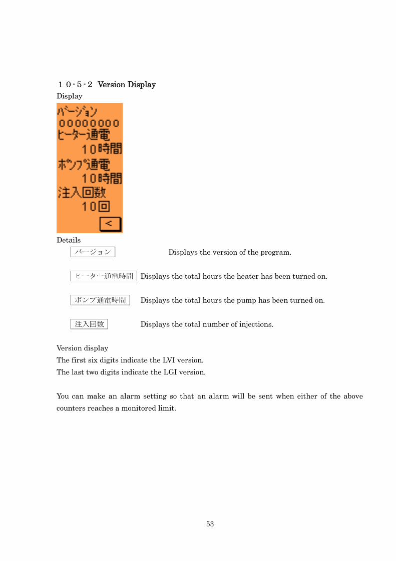
バージョン Displays the version of the program.
ヒーター通電時間 Displays the total hours the heater has been turned on.
ポンプ通電時間 Displays the total hours the pump has been turned on.
注入回数 Displays the total number of injections.
Version display
The first six digits indicate the LVI version.
The last two digits indicate the LGI version.
You can make an alarm setting so that an alarm will be sent when either of the above
counters reaches a monitored limit.
54
10-5-3 Error Log
Display
Details
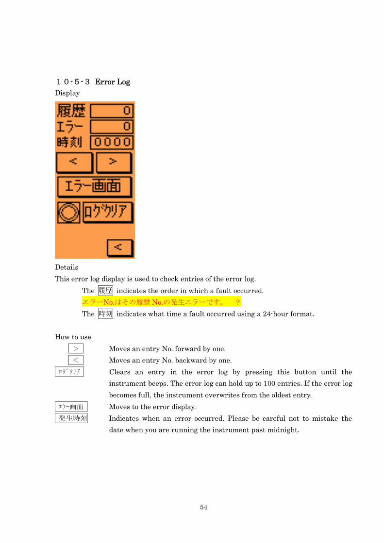
This error log display is used to check entries of the error log.
The 履歴 indicates the order in which a fault occurred.
エラーNo.はその履歴 No.の発生エラーです。 ?
The 時刻 indicates what time a fault occurred using a 24-hour format.
How to use
> Moves an entry No. forward by one.
< Moves an entry No. backward by one.
ログクリア Clears an entry in the error log by pressing this button until the
instrument beeps. The error log can hold up to 100 entries. If the error log
becomes full, the instrument overwrites from the oldest entry.
エラー画面 Moves to the error display.
発生時刻 Indicates when an error occurred. Please be careful not to mistake the
date when you are running the instrument past midnight.
55
10-5-4 Error Display
Display
Details
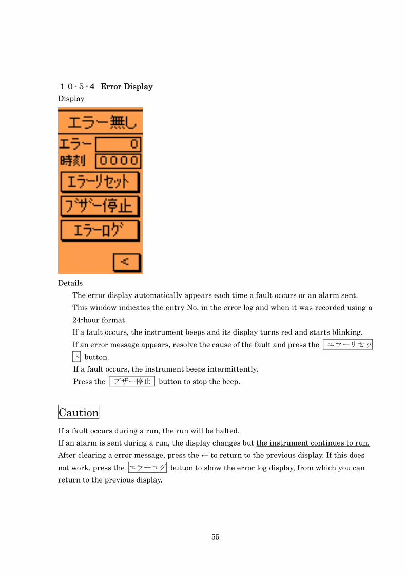
The error display automatically appears each time a fault occurs or an alarm sent.
This window indicates the entry No. in the error log and when it was recorded using a
24-hour format.
If a fault occurs, the instrument beeps and its display turns red and starts blinking.
If an error message appears, resolve the cause of the fault and press the エラーリセッ
ト button.
If a fault occurs, the instrument beeps intermittently.
Press the ブザー停止 button to stop the beep.
Caution
If a fault occurs during a run, the run will be halted.
If an alarm is sent during a run, the display changes but the instrument continues to run.
After clearing a error message, press the ← to return to the previous display. If this does
not work, press the エラーログ button to show the error log display, from which you can
return to the previous display.
56
10-5-5 Clearing Memory
Display
Caution
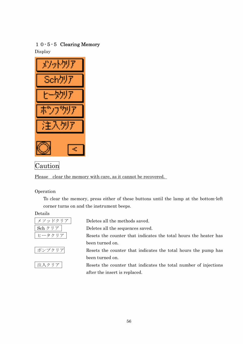
Please clear the memory with care, as it cannot be recovered.
Operation
To clear the memory, press either of these buttons until the lamp at the bottom-left
corner turns on and the instrument beeps.
Details
メソッドクリア Deletes all the methods saved.
Sch クリア Deletes all the sequences saved.
ヒータクリア Resets the counter that indicates the total hours the heater has
been turned on.
ポンプクリア Resets the counter that indicates the total hours the pump has
been turned on.
注入クリア Resets the counter that indicates the total number of injections
after the insert is replaced.

57
10-5-6 Setting Alarm
Display
Details
アラーム切 Turns off the alarm, regardless of monitored limits.
アラーム入 Sends an alarm if either of these counters reaches a monitored limit.
When an alarm is sent, the display turns to red, but the instrument does
not beep or stop the operation.
注入回数 Sends an alarm if the total number of injections reaches the limit you set.
Use this alarm to let you know the appropriate timing for the replacement
of the septum and insert.
ヒーター時間 Sends an alarm if the counter for the total hours the heater has been
turned on reaches a monitored limit. Use this alarm to let you know the
appropriate timing for the inspection of the heater.
ポンプ時間 Sends an alarm if the counter for the total hours the pump has been
turned reaches a monitored limit. Use the alarm to let you know the
appropriate timing for the inspection of the pump.
Caution
Alarms for the pump and the heater will be sent, if any, when you turn on the LVI
controller.
If you set a higher limit than the warranted values, the instrument could become damaged

58
before any alarm notification.
The range of alarm parameters is up to 30,000.
59
11 ALARMS AND ERROR MESSAGES
Caution
If an alarm is sent during the middle of a run, the instrument continues operation. If an
error message is generated during the middle of a run, the instrument aborts the run.
After clearing an error messages, see Chapter 7, “Maintenance,” if maintenance is
necessary.
11-1 List of Error Messages
No.1 Malfunction of the air pump
Air delivery pressure is not enough. Check for a disconnected air tube. If the air
tube is connected, see page 25.
No.2 Malfunction of the pressure sensor
The pressure sensor fails. Contact our distributor or us for the LVI to replace it.
No.3 Malfunction in the temperature control function
The instrument does not stabilize at a temperature setpoint. This could happen
when the starting temperature setpoint of the GC oven is higher than that of the
inlet. Check for a disconnected connector of the heater.
No.4 Malfunction of the heater
The heater could be burned out. Set the oven temperature setpoint at about 80
C and run the instrument to see if the actual value of the temperature will change.
If not, contact our distributor or us for the LVI.
No.6 Malfunction of the temperature sensor
The connector for the temperature sensor could be disconnected. Or, the
temperature sensor could be broken. If the sensor is broken, contact our
distributor or us for the LVI to replace it.
No.7 A sample has been injected before the instrument stabilizes at a temperature
setpoint.
A sample has been injected before the instrument stabilizes at a temperature
60
setpoint.
No.8 Malfunction of the CPU battery
The memory backup battery is low. Contact our distributor or us for the LVI.
No.9 Not defined
11-2 Alarms
No.11 You cannot edit the method.
You are trying to overwrite a method with a different user No. from your own.
No.12 Alarm for the number of repetitions of a method
In the repeat operation mode, a method has been repeated over the limit you set.
No.13 Alarm for the number of injections
The number of injections has reached the limit you set for the alarm. Carry out
maintenance work on the septa and the insert. (This alarm is sent only if you
make the alarm setting.)
No.14 Alarm for the time the heater has been turned on.
The heater has been operated for longer than the limit you set. (This alarm is sent
only if you make the alarm setting.)
No.15 Alarm for the time the air pump has been turned on.
The air pump has been operated for longer than the limit you set. (This alarm is
sent only if you make the alarm setting.)
61
12 FREQUENTLY ASKED QUESTIONS (FAQ)[Q1] An error message for a malfunction of the air pump appears.
A1. If an error message for the air pump appears, follow the instructions below.
① Check for disconnected (or loosened) tubing.
Pull the tube to see if it will not come off. Even if not, there could be a leak from a
loosely connected tube. Insert the tube as far as it goes.
・Check the tubing from the air pump.
・Check the tubing on the T-shaped connecter near the back of the LVI controller.
・Check the tubing connected to the heater near the LVI inlet.
② Confirm that the filter on the suction side of the pump is not clogged.
Run the instrument without the filter to see if the problem will remain. If not, replace
the filter.
③ If the same problem remains when you run the instrument without the filter, the
discharge pressure of the air pump could be insufficient. Replace the air pump. (The
air pump is warranted for six months from the date of shipment.)
[Q2] An error message for a malfunction of the temperature sensor appears.
A2. If an error message for the temperature sensor appears, follow the instructions below.
① Confirm that the sensor cable (with a blue connecter connected to the back of the LVI
controller) is not disconnected. Insert its plug all the way into the jack.
② Remove the top cover of the LVI inlet so that you can see the insert. Confirm that the
sensor projects approximately 5 mm from the inner surface of the inlet. If you find
anything wrong, please contact our distributor or us for the LVI.
③ If you cannot find any of the problems above, the temperature sensor cable could be
broken. Please contact our distributor or us for the LVI.
[Q3] An error message for a malfunction of the heater appears.
62
A3. If an error message for a malfunction of the heater appears, follow the instructions
below. It takes approximately 10 minutes for the LVI to detect a malfunction of the heater.
Be assured that nothing is wrong with the LVI when it takes some while to generate an
error message for a malfunction of the heater.
①. The LVI controller display indicates that the actual temperature of the instrument has
risen, but it is fluctuating between too high and too low values for a temperature
setpoint and an error message appears.
→Air flow from the air pump could be insufficient. Refer to the [Q1], “An error message
for a malfunction of the air pump appears.”
②. The LVI controller display indicates that an actual temperature does not rise to a
temperature setpoint and stays under the ambient temperature.
→ The heater could be burned out. Replace the heater by following the instructions in
this manual on the replacement of the heater.
[Q4] A method you saved on the LVI controller is cleared.
The LVI controller does not retain the parameters you saved last time, but indicates
the default values.
A4. The memory backup battery placed in the controller could be low. Replace the battery
by following the instructions in this manual on the replacement of the battery.
[Q5] The sensitivity is low.
A5. If the sensitivity is low, there could be a problem not only in the LVI inlet, but also in
the detector, or both. Follow the steps below to find and troubleshoot a problem in the LVI.
①. Check that a sample has been injected.
→ Check that the syringe of the auto sampler precisely aspirates the defined volume
of sample and injects it into the inlet.
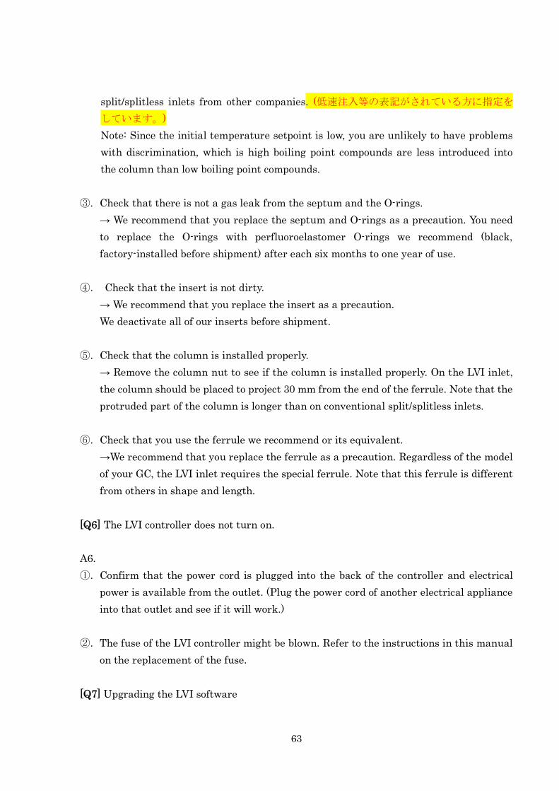
②. Check that sample injection speed is appropriate.
→On the LVI inlet, sample injection speed should be set relatively lower than on
63
split/splitless inlets from other companies. (低速注入等の表記がされている方に指定を
しています。)
Note: Since the initial temperature setpoint is low, you are unlikely to have problems
with discrimination, which is high boiling point compounds are less introduced into
the column than low boiling point compounds.
③. Check that there is not a gas leak from the septum and the O-rings.
→ We recommend that you replace the septum and O-rings as a precaution. You need
to replace the O-rings with perfluoroelastomer O-rings we recommend (black,
factory-installed before shipment) after each six months to one year of use.
④. Check that the insert is not dirty.
→ We recommend that you replace the insert as a precaution.
We deactivate all of our inserts before shipment.
⑤. Check that the column is installed properly.
→ Remove the column nut to see if the column is installed properly. On the LVI inlet,
the column should be placed to project 30 mm from the end of the ferrule. Note that the
protruded part of the column is longer than on conventional split/splitless inlets.
⑥. Check that you use the ferrule we recommend or its equivalent.
→We recommend that you replace the ferrule as a precaution. Regardless of the model
of your GC, the LVI inlet requires the special ferrule. Note that this ferrule is different
from others in shape and length.
[Q6] The LVI controller does not turn on.
A6.
①. Confirm that the power cord is plugged into the back of the controller and electrical
power is available from the outlet. (Plug the power cord of another electrical appliance
into that outlet and see if it will work.)
②. The fuse of the LVI controller might be blown. Refer to the instructions in this manual
on the replacement of the fuse.
[Q7] Upgrading the LVI software
64
A7. You can download the latest software from our website for free by entering the
password, the same as the one for installation which is indicated in the instruction
manual.
[Q8] An error message for a malfunction of the temperature control appears.
A8. If an error message for a malfunction of the temperature control appears, there are
three possible causes as below.
①. The initial temperature setpoint of the GC oven is higher than that of the LVI inlet.
→ Since the LVI inlet is installed on top of the GC oven, it is affected by the heat from
the oven. To re-concentrate an injected sample at the end of the column, set the GC
oven temperature at 10 C lower than the initial temperature setpoint of the LVI inlet.
② The initial temperature setpoint of the LVI inlet is lower than the ambient
temperature.
→ Refrigerant is not used on the LVI to lower running costs, instead, ambient air is
pumped into the inlet to cool it down. This makes it impossible for the inlet to become
cooler than the ambient air. For practical use, the initial temperature setpoint of the
inlet should be set at 40 C or higher. It should be set to 60 C or higher for stable
operation.
③ Either of the heater, the sensor or the air pump is likely to fail.
→ Refer to the Q1 to Q3.
65
Warranty Policy
Thank you for your purchase of the LVI-S200.
This instrument is warranted under the following conditions:
Warranty Period Warranty period is one year from the day of installation.
Warranty Coverage If a defect arises due to our fault within the warranty period, we
will repair the instrument or replace its parts at no charge.
Warranty Exclusions Even within the warranty period, no warranty will apply to the
instrument that has malfunctioned resulting from:
(1) Improper operation.
(2) Repair or modification performed by any personnel other than
us or the parties authorized by us.
(3) Any causes other than a failure of the LVI.
(4) The use under harsh conditions such as in a site where the air
is hot and humid or contains a corrosive gas, or the instrument
is shaken.
(5) Fires, earthquakes, or other natural disasters.
(6) Relocation or transportation of the instrument after
installation.
(7) A fault of the consumables and their equivalents.
66
Manufacturer: Aisti Science Co., Ltd.
Assort Kuroda Bldg. 2F
120-6, Kuroda, Wakayama 640-8341 Japan
TEL: +81-73-475-0033
FAX: +81-73-497-5011
URL http://www.aisti.co.jp
Email: [email protected]


![SPRING S200 S250 S200 から MOMENTUM S250 へのアップグレードサービス [SPRING アップグレードキャンペーン ]](https://img.dokumen.tips/doc/110x75/5cc6f90488c99368098dda59/spring-s200-s200-momentum-s250-spring.jpg)