Embed Size (px)
Citation preview

1
www.milwaukeeinst.com
EC/TDS MeterEC/TDS MeterEC/TDS MeterEC/TDS MeterEC/TDS Meter
Mi 306AAAAAutomatic & Lutomatic & Lutomatic & Lutomatic & Lutomatic & Logging EC/TDS Meterogging EC/TDS Meterogging EC/TDS Meterogging EC/TDS Meterogging EC/TDS Meter
INSTRUCTION MANUAL

Instruction Manual Mi 306 EC/TDS Meter
22222
FUNCTIONAL DESCRIPTION .................................................................................... 2GENERAL DESCRIPTION ........................................................................................... 4PROBE MAINTENANCE ............................................................................................ 5SPECIFICATION ....................................................................................................... 5SETUP ...................................................................................................................... 7TAKING MEASUREMENTS ......................................................................................... 9AUTORANGING .................................................................................................... 10AUTO ENDPOINT MODE ....................................................................................... 10TEMPERATURE COMPENSATION ............................................................................ 11EC/TDS CALIBRATION ............................................................................................ 12NACL CALIBRATION ............................................................................................... 13LOGGING FUNCTION .......................................................................................... 14DATA TRANSFER TO PC .......................................................................................... 17BATTERY REPLACEMENT ......................................................................................... 18CONDUCTIVITY VS TEMPERATURE CHART .............................................................. 18ACCESSORIES ........................................................................................................ 19
DISPLAYDISPLAYDISPLAYDISPLAYDISPLAYA. PRIMARY DISPLAYB. AUTO ENDPOINT MODE
INDICATORC. LOW BATTERY INDICATORD. CALIBRATION MODE INDICATORE. REQUIRE USER CONFIRMATIONF. CALIBRATION TAGSG. MEASURING UNIT FOR PRIMARY
DISPLAYH. PRIMARY DISPLAY MODEI. MEASURING UNIT FOR
SECONDARY DISPLAYJ. SECONDARY DISPLAY
FUNCTIONAL DESCRIPTION
B
C
H
D
E
F J
G
I
A

www.milwaukeeinst.com
3
FUNCTIONAL DESCRIPTION
1. Liquid Crystal Display (LCD)
2. ON/OFF key, to turn the meter onand off
3. RANGE/FIXED key, to select mea-surement range or (with SHIFT) to fixthe current range.
4. ▲/SETUP key, to move up or (withSHIFT) to enter setup mode.
5. ATC/TC key, to select temperaturecompensation mode or (with SHIFT)to view the temperature coefficientvalue.
6. MEM/MR key, to store or (with SHIFT)recall measurements.
7. ▼/CFM key, to move down or (withSHIFT) to confirm displayed choice.
8. SHIFT key, to enable inverse functions.
9. CAL/HOLD key, to enter calibrationmode or (with SHIFT) to enter AutoEndpoint mode.
10. DIN connector for probe
11. RS232 plug
Instruction Manual Mi 306 EC/TDS Meter
44444
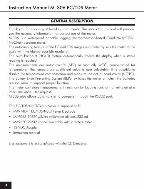
GENERAL DESCRIPTION
Thank you for choosing Milwaukee Instruments. This instruction manual will provide you the necessary information for correct use of the meter.Mi306 is a waterproof portable logging microprocessor-based Conductivity/TDS/NaCl/temperature meter.The autoranging feature of the EC and TDS ranges automatically sets the meter to the scale with the highest possible resolution.The Auto Endpoint (HOLD) feature automatically freezes the display when a stable reading is reached.The measurements are automatically (ATC) or manually (MTC) compensated for temperature. The temperature coefficient value is user selectable. It is possible to disable the temperature compensation and measure the actual conductivity (NOTC). The Battery Error Preventing System (BEPS) switches the meter off when the batteries are too weak to support proper function.The meter can store measurements in memory by logging function for retrieval at a later time upon user request.Mi306 also allows data transfer to computer through the RS232 port.
This EC/TDS/NaCl/Temp Meter is supplied with:
• MA914D/1 EC/TDS/NaCl Temp Electrode
• MA9066 12880 μS/cm calibration olution, 230 mL
• MA9350 RS232 connection cable with 2 meters cable
• 12 VDC Adapter
• Instruction manual
This instrument is in compliance with the CE Directives.
www.milwaukeeinst.com
5
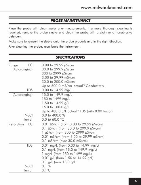
SPECIFICATIONS
Range EC 0.00 to 29.99 μS/cm(Autoranging) 30.0 to 299.9 μS/cm
300 to 2999 μS/cm3.00 to 29.99 mS/cm30.0 to 200.0 mS/cmUp to 500.0 mS/cm actual(*) Conductivity
TDS 0.00 to 14.99 mg/L(Autoranging) 15.0 to 149.9 mg/L
150 to 1499 mg/L1.50 to 14.99 g/L15.0 to 100.0 g/LUp to 400.0 g/L actual(*) TDS (with 0.80 factor)
NaCl 0.0 to 400.0 %Temp. 0.0 to 60.0 °C
Resolution EC 0.01 μS/cm (from 0.00 to 29.99 μS/cm)0.1 μS/cm (from 30.0 to 299.9 μS/cm)1 μS/cm (from 300 to 2999 μS/cm)0.01 mS/cm (from 3.00 to 29.99 mS/cm)0.1 mS/cm (over 30.0 mS/cm)
TDS 0.01 mg/L (from 0.00 to 14.99 mg/L)0.1 mg/L (from 15.0 to 149.9 mg/L)1 mg/L (from 150 to 1499 mg/L)0.01 g/L (from 1.50 to 14.99 g/L)0.1 g/L (over 15.0 g/L)
NaCl 0.1 %Temp. 0.1°C
PROBE MAINTENANCE
Rinse the probe with clean water after measurements. If a more thorough cleaning isrequired, remove the probe sleeve and clean the probe with a cloth or a nonabrasivedetergent.
Make sure to reinsert the sleeve onto the probe properly and in the right direction.
After cleaning the probe, recalibrate the instrument.

Instruction Manual Mi 306 EC/TDS Meter
66666
SPECIFICATIONS
Accuracy EC ±1% of reading (±0.05 μs/cm or 1 digit whichevergreater)
TDS ±1% of reading (±0.053 ppm or 1 digit whichever greater)NaCl ±1% of reading
Temp. ±0.4°CTypical EMC EC ±1% of readingDeviation TDS ±1% of reading
NaCl ±1% of readingTemp. ±0.1 °C
Logging 250 records, LOG on demand or auto-loggingCommunication with PC - RS232EC Calibration 1 point with 7 memorized buffers: 0, 84, 1413, 5000,
12880, 80000, 111800 μS/cmNaCl Calibration 1 point with HI 7037 buffer (optional)Temperature 2 points at 0 and 50°CCalibration (plus ±1°C adjustment)Temperature Automatic or Manual from 0 to 60°CCompensation (can be disabled to measure actual conductivity)Temperature 0.00 to 6.00 %/°C (for EC and TDS only)Coefficient Default value is 1.90%/°CReference Temp. 20 or 25 °CTDS Factor 0.40 to 0.80 (default value is 0.50)Probe MA 814D/1 EC probe with built-in temperature sensor
& 1.1 m cable (included)Auto Off After 5 minutes (can be disabled)Power supply 9V Battery (included) - approx. 100 hours of useCasing IP 67Environment 0 to 50°C ; 100% RHDimensions 200 x 85 x 50 mm (7.9 x 3.3 x 2.0")Weight 280 g (10 oz)

www.milwaukeeinst.com
7
SETUP
Setup is used to view or change the instrument parameters.
To enter setup press SHIFT+SETUP when the meter is in measure-ment mode.
"Set" is displayed on the upper LCD. The lower LCD displays the blinking code of thecurrent setup item.
Select the desired setup item using the ▲ or ▼ key.
Press SHIFT+CFM to confirm.
Note:Note:Note:Note:Note: If SHIFT+SETUP are pressed before item confirmation, the meter will escape andreturn to measurement mode.
Once the desired setup item has been selected, its current value blinks (if it is achangeable parameter).
Instruction Manual Mi 306 EC/TDS Meter
88888
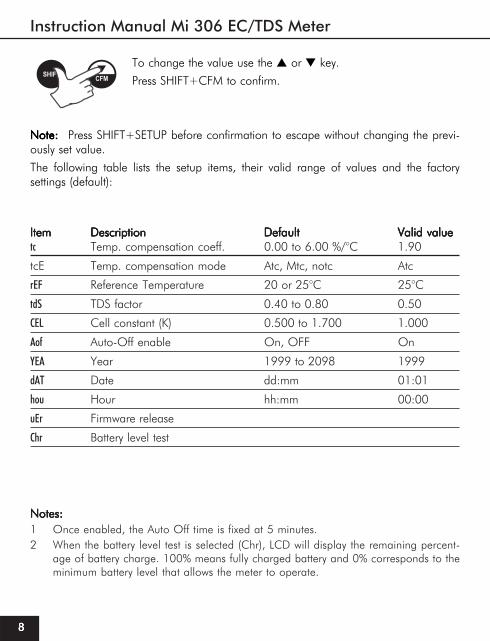
ItemItemItemItemItem DescriptionDescriptionDescriptionDescriptionDescription DefaultDefaultDefaultDefaultDefault Valid valueValid valueValid valueValid valueValid valuetc Temp. compensation coeff. 0.00 to 6.00 %/°C 1.90
tcE Temp. compensation mode Atc, Mtc, notc Atc
rEF Reference Temperature 20 or 25°C 25°C
tdS TDS factor 0.40 to 0.80 0.50
CEL Cell constant (K) 0.500 to 1.700 1.000
Aof Auto-Off enable On, OFF On
YEA Year 1999 to 2098 1999
dAT Date dd:mm 01:01
hou Hour hh:mm 00:00
uEr Firmware release
Chr Battery level test
To change the value use the ▲ or ▼ key.
Press SHIFT+CFM to confirm.
Note:Note:Note:Note:Note: Press SHIFT+SETUP before confirmation to escape without changing the previ-ously set value.
The following table lists the setup items, their valid range of values and the factorysettings (default):
Notes:Notes:Notes:Notes:Notes:1 Once enabled, the Auto Off time is fixed at 5 minutes.2 When the battery level test is selected (Chr), LCD will display the remaining percent-
age of battery charge. 100% means fully charged battery and 0% corresponds to theminimum battery level that allows the meter to operate.
www.milwaukeeinst.com
9
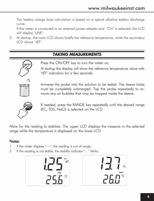
TAKING MEASUREMENTS
Press the ON/OFF key to turn the meter on.
At startup the display will show the reference temperature value with"rEF" indication for a few seconds.
Immerse the probe into the solution to be tested. The sleeve holesmust be completely submerged. Tap the probe repeatedly to re-move any air bubbles that may be trapped inside the sleeve.
If needed, press the RANGE key repeatedly until the desired range(EC, TDS, NaCl) is selected on the LCD.
Allow for the reading to stabilize. The upper LCD displays the measure in the selectedrange while the temperature is displayed on the lower LCD.
Notes:Notes:Notes:Notes:Notes:1 If the meter displays "----", the reading is out of range.2 If the reading is not stable, the stability indicator " " blinks.
The battery charge level calculation is based on a typical alkaline battery dischargecurve.If the meter is connected to an external power adapter and "Chr" is selected, the LCDwill display "LINE".
3 At startup, the main LCD shows briefly the reference temperature, while the secondaryLCD shows "rEF".

Instruction Manual Mi 306 EC/TDS Meter
1010101010
3 Make sure the meter is calibrated before taking measurements.4 If measurements are taken successively in different samples, to have accurate readings it is
recommended to rinse the probe thoroughly with deionized water before immersion in thesamples.
5 To maximize battery life, the meter is automatically switched off after 5 minutes of non-use. Toreactivate the instrument press the ON/OFF key. This feature can be disabled by entering thesetup mode and selecting the "AoF" item (see SETUP section for details).
6 TDS reading is obtained multiplying the EC reading by the TDS factor, which has a defaultvalue of 0.50. It is possible to change the TDS factor in the 0.40 to 0.80 range by enteringthe setup mode and selecting the "tdS" item (see SETUP section). Always set the referencetemperature to 25°C when measuring TDS.
7 When the use of an alternate function (MR, SETUP, CFM, FIXED, TC and HOLD) isrequested, press and hold the SHIFT key first and then the second key.
AUTORANGING
The EC and TDS scales are autoranging. The meter automatically sets the scale withthe highest possible resolution.
By pressing SHIFT+FIXED, the autoranging feature is disabled and thecurrent range is frozen on the LCD. "FIXED" symbol blinks on the LCD.To restore the autoranging option press SHIFT+FIXED again.
Note: Autoranging is automatically restored if the RANGE key is pressed, if the setup orcalibration modes are entered and if the meter is turned off and back on again.
AUTO ENDPOINT MODE
The Auto Endpoint feature allows the user to freeze the display, when a stable reading isreached (EC/TDS/NaCl and temperature range).
To enter the Auto Endpoint mode, press SHIFT+HOLD keys.
www.milwaukeeinst.com
11
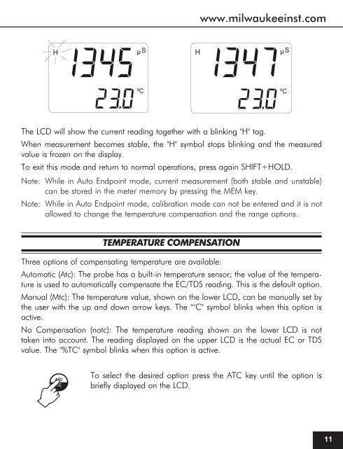
The LCD will show the current reading together with a blinking "H" tag.
When measurement becomes stable, the "H" symbol stops blinking and the measuredvalue is frozen on the display.
To exit this mode and return to normal operations, press again SHIFT+HOLD.
Note: While in Auto Endpoint mode, current measurement (both stable and unstable)can be stored in the meter memory by pressing the MEM key.
Note: While in Auto Endpoint mode, calibration mode can not be entered and it is notallowed to change the temperature compensation and the range options.
TEMPERATURE COMPENSATION
Three options of compensating temperature are available:
Automatic (Atc): The probe has a built-in temperature sensor; the value of the tempera-ture is used to automatically compensate the EC/TDS reading. This is the default option.
Manual (Mtc): The temperature value, shown on the lower LCD, can be manually set bythe user with the up and down arrow keys. The "°C" symbol blinks when this option isactive.
No Compensation (notc): The temperature reading shown on the lower LCD is nottaken into account. The reading displayed on the upper LCD is the actual EC or TDSvalue. The "%TC" symbol blinks when this option is active.
To select the desired option press the ATC key until the option isbriefly displayed on the LCD.

Instruction Manual Mi 306 EC/TDS Meter
1212121212
If temperature compensation is active, measurements are compensated using a defaulttemperature coefficient of 1.90 %/°C.
It is possible to select a different temperature coefficient (TC) in the 0.00 to 6.00 %/°Crange by entering the setup mode and selecting the "tc" item (see SETUP section fordetails).
The current temperature coefficient can be quickly viewed pressingSHIFT+ATC. The value is briefly displayed on the lower LCD.
EC/TDS CALIBRATION
EC calibration is a single point procedure. Selectable calibration points are: 0.0, 84.0μS/cm, 1413 μS/cm, 5.00 mS/cm, 12.88 mS/cm, 80.0 mS/cm,111.8 mS/cm.
To enter EC calibration select the EC range and press the CAL key.
Note: TDS reading is automatically derived from the EC reading and no specificcalibration for TDS is needed. Pressing CAL while TDS range is selected has noeffect.
Rinse the probe with some of the calibration solution or deionized water. Immerse theprobe into the solution. The sleeve holes must be completely submerged. Tap the proberepeatedly to remove any air bubbles that may be trapped inside the sleeve.
Begin with Zero calibration, just leave the dry probe in air.
The indications "REF" and "CAL" are displayed. The upper LCD shows the uncalibratedEC reading. The lower LCD shows the buffer value. The stability indicator " " blinks.
Select the desired value of buffer with the ▲ and ▼ keys, ifnecessary.

www.milwaukeeinst.com
13
When the " " symbol stops blinking, the reading is stable. The "CFM" indication startsblinking on the LCD asking for confirmation.
Press SHIFT+CFM to confirm the calibration.
If everything is satisfactory, the meter displays the "Stor Good"message and returns to measurement mode.
NotesI. The meter uses 1.90%/°C compensation factor during calibration. If the setup item
"tc" has been set to a different value, when exiting the calibration mode the valuedisplayed on the upper LCD could be different from the nominal buffer value.
II. It is possible to set the cell constant value directly without following the calibrationprocedure. To set the cell constant enter the setup mode and select "CEL" (see SETUPfor details).
III. Press SHIFT+CFM to confirm. The meter returns to measurement mode.
NaCl CALIBRATION
Calibration is 1-point at 100.0% NaCl. Use the MA 9066 calibration solution (sea water solution) as a 100% NaCl standard solution.• To enter NaCl calibration select the NaCl from “RANGE” key and press CAL.• Rinse the probe with some of the calibration solution or deionized water. Immerse the
probe into MA9066 solution. The sleeve holes must be completely submerged. Tap the probe repeatedly to remove any air bubbles that may be trapped inside the sleeve.
• The indications "STD" and "CAL" are displayed. The upper LCD shows the uncalibratedNaCl reading in percentage. The lower LCD shows "100".
• When the " " symbol stops blinking, the reading is stable. The "CFM" indicationstarts blinking on the LCD asking for confirmation.
• Press SHIFT+CFM to confirm the calibration.
• If everything is satisfactory, the meter displays the "Stor Good" message and returns tomeasurement mode.
Note: If the uncalibrated reading is too far from the expected value, the calibration isnot recognized. The "CFM" indication does not appear; the " " and "STD"symbols blink to signal wrong or contaminated calibration solution.
Instruction Manual Mi 306 EC/TDS Meter
1414141414
LOGGING FUNCTION
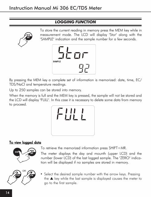
To store the current reading in memory press the MEM key while inmeasurement mode. The LCD will display "Stor" along with the"SAMPLE" indication and the sample number for a few seconds.
By pressing the MEM key a complete set of information is memorized: date, time, EC/TDS/NaCl and temperature readings.
Up to 250 samples can be stored into memory.
When the memory is full and the MEM key is pressed, the sample will not be stored andthe LCD will display "FULL". In this case it is necessary to delete some data from memoryto proceed.
To view logged dataTo view logged dataTo view logged dataTo view logged dataTo view logged data
To retrieve the memorized information press SHIFT+MR.
The meter displays the day and mounth (upper LCD) and thenumber (lower LCD) of the last logged sample. The "ZERO" indica-tion will be displayed if no samples are stored in memory.
• Select the desired sample number with the arrow keys. Pressingthe ▲ key while the last sample is displayed causes the meter togo to the first sample.

www.milwaukeeinst.com
15
• Press RANGE to view remaining data of the selected sample.After the date information, the remaining data will be displayedin the following order:
year hour
• It is always possible to skip to another sample using the up and down arrow keys.For example, if the reading of a sample is displayed, pressing the up arrow keywill cause the meter to display the reading of the next sample.
• At any time it is possible to return to normal operational mode by pressingSHIFT+MR.
- temperature reading"----" means reading out of range.
- EC, TDS, NaCL reading"----" means reading out of range
or no probe was connected.

Instruction Manual Mi 306 EC/TDS Meter
1616161616
To delete logged dataTo delete logged dataTo delete logged dataTo delete logged dataTo delete logged data
It is possible to delete a single sample or all the memory at one time.
To delete a single sample:
• Enter the viewing logged data mode and select the desiredsample number.
• Press SHIFT+HOLD. The "CFM" indication starts blinking askingfor confirmation.
• Press the SHIFT+CFM to confirm deletion.
Note: Press SHIFT+HOLD to escape without data deletion.When viewing through the logged data, the "NULL" message will be displayed whenselecting a deleted sample.
To delete all data in memory:To delete all data in memory:To delete all data in memory:To delete all data in memory:To delete all data in memory:
• Enter the viewing logged data mode.
• Press SHIFT+TC. The "CFM" indication will start blinking askingfor confirmation.
• Press SHIFT and CFM to confirm deletion.
Note: Press SHIFT+TC to escape without data deletion.
Note: If no samples are stored in memory and a deletion is attempted, the meter willshow the message "Zero" and then returns to normal operational mode.

www.milwaukeeinst.com
17
DATA TRANSFER TO PC
Connect the meter to a PC through the RS232C output (the connector is located on thetop of the meter). Use MA 9351MA 9351MA 9351MA 9351MA 9351(5 to 9 pin) connection cable.
SpecificationsSpecificationsSpecificationsSpecificationsSpecifications
Isolated 8-bit data transmission
Baud Rate: 2400
Start bit: 1
Stop bit: 1
Parity bit: none
Sending Commands from PCSending Commands from PCSending Commands from PCSending Commands from PCSending Commands from PC
With any terminal programs it is possible to remotely control the instrument. Connectthe meter to the PC through the MA 9351MA 9351MA 9351MA 9351MA 9351 cable, start the terminal program and set thecommunication options as follows: 8, N, 1, no flow control.
To send a command to the meter the scheme is:
<command> <CR>
The computer sends the command expressed as a 3-character sequence and a CRcharacter.
Note:Note:Note:Note:Note: All the terminal programs that support the ANSI escape sequence, represent theCR character with the string '^M'.
The commands available are as follows:MOD - to request the firmware code of the meter.RPA - to request the setup parameters setting.LTB - to request the number of logged samples.LOD - to request the logged data.
The meter answers with the following order:status bytedate (ddmmyy)time (hhmm)measurement (binary)temperature reading (binary)At the end of the logged data the checksum (2 complement) is sent.
Note:Note:Note:Note:Note: The meter will send <CAN> if a corrupted or unknown command is received.

Instruction Manual Mi 306 EC/TDS Meter
1818181818
BATTERY REPLACEMENT
When the battery is low the meter will display the blinking battery symbol in the lower leftcorner of the LCD.
When the battery indicator appears, the meter can still work for about 20 hours.
A low battery condition will lead to unreliable readings. It is recommended to replaceimmediately the battery.
Battery replacement must only take place in a non-hazardous area using a 9V alkalinebattery. Turn the meter off, remove the battery compartment cover on the rear of themeter and replace the rundown battery with a new one.
Install the battery while paying attention to its polarity and reattach the cover.
CONDUCTIVITY VS TEMPERATURE CHART
The conductivity of an aqueous solution is the measure of its ability to carry an electricalcurrent by means of ionic motion. The conductivity invariably increases with increasingtemperature. It is affected by the type and number of ions in the solution and by theviscosity of the solution itself. Both parameters are temperature dependent. The depen-dency of conductivity on temperature is expressed as a relative change per degreeCelsius at a particular temperature, commonly as percent per °C.
The following table lists the temperature dependence of the calibration buffers.°C °F - - - - - -
(µS/cm)19 66.2 11430 1251 74 71300 100200 442920 68 11670 1278 76 72400 102100 452321 69.8 11910 1305 78 74000 104000 461722 71.6 12150 1332 79 75200 105900 471123 73.4 12390 1359 81 76500 107900 480524 75.2 12640 1386 82 78300 109800 490225 77 1288012880128801288012880 14131413141314131413 8484848484 8000080000800008000080000 111800111800111800111800111800 5000500050005000500026 78.8 13130 1440 86 81300 113800 509627 80.6 13370 1467 87 83000 115700 519028 82.4 13620 1494 89 84900 117700 528629 84.2 13870 1521 90 86300 119700 538330 86 14120 1548 92 88200 121800 547931 87.8 14370 1575 94 90000 123900 5575

www.milwaukeeinst.com
19
ACCESSORIES
MA 814D/1MA 814D/1MA 814D/1MA 814D/1MA 814D/1 4-ring EC probe with DIN connector and 1 m (3.3’) cable
M1 0030BM1 0030BM1 0030BM1 0030BM1 0030B 12880 μS/cm calibration solution, 20 ml sachet, 25 pcs.
M1 0031BM1 0031BM1 0031BM1 0031BM1 0031B 1413 μS/cm calibration solution, 20 ml sachet, 25 pcs.
M1 0033BM1 0033BM1 0033BM1 0033BM1 0033B 84 μS/cm calibration solution, 20 ml sachet, 25 pcs.
M1 0035BM1 0035BM1 0035BM1 0035BM1 0035B 111.8 mS/cm calibration solution, 20 ml sachet, 25 pcs.
MA 9060MA 9060MA 9060MA 9060MA 9060 12880 μS/cm calibration solution, 230 ml bottle
MA 9061MA 9061MA 9061MA 9061MA 9061 1413 μS/cm calibration solution, 230 ml bottle
MA 9063MA 9063MA 9063MA 9063MA 9063 84 μS/cm calibration solution, 230 ml bottle
MA 9065MA 9065MA 9065MA 9065MA 9065 111.8 mS/cm calibration solution, 230 ml bottle
MA 9069MA 9069MA 9069MA 9069MA 9069 5000 μS/cm solution, 230 ml bottle
MA 9351MA 9351MA 9351MA 9351MA 9351 RS232 connection cable (5 to 9 pin) with 2 meters cable (for Mi306)
MA 9066MA 9066MA 9066MA 9066MA 9066 100% NaCl Calibration solution, 230 ml bottle
WARRANTYWARRANTYWARRANTYWARRANTYWARRANTYThese instruments are warranted against defects in materials and manufacturing for aperiod of 3 years from the date of purchase. Electrodes and Probes are warranted for 6months.If during this period the repair or replacement of parts is required, where thedamage is not due to negligence or erroneous operation by the user, please returnthe intruments, electrode and probe to either distributor or our office and the repairwill be effected free of charge.Damage due to accidents, misuse, tampering or lack of prescribed maintenance isnot covered by the warranty.
Milwaukee instruments reserves the right to make improvements in design, construction and appearance of its products without advance notice.
For your Safety don’t use or store the instrument in hazardous environments. To avoiddamages or burns, do not perform any measurement in microwave ovens.

THANK YOU FOR CHOOSING
Sales and Technical Service Contacts:
Milwaukee Electronics Kft.Alsókikötő sor 11.
6726, Szeged, HungaryTel: +36-62-428-050Fax: +36-62-428-051
e-mail: [email protected]
Milwaukee Instruments, Inc.2950 Business Park Drive Rocky Mount, NC
27804 USATel: +1 252 443 3630Fax: +1 252 443 1937
e-mail: [email protected]
www.milwaukeeinst.com
MANMI306 23/06