Embed Size (px)
Citation preview
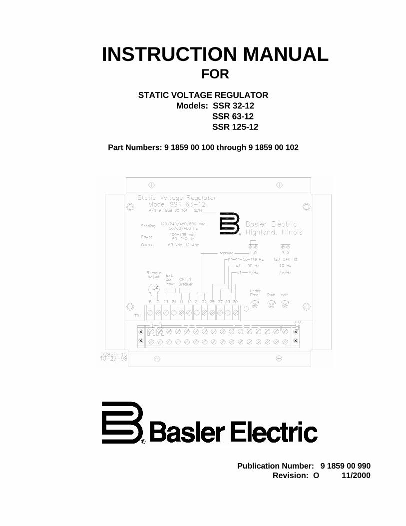
INSTRUCTION MANUALFOR
STATIC VOLTAGE REGULATORModels: SSR 32-12
SSR 63-12SSR 125-12
Part Numbers: 9 1859 00 100 through 9 1859 00 102
Publication Number: 9 1859 00 990Revision: O 11/2000

SSR Introduction i
INTRODUCTION
This manual provides information concerning the operation and installation of Static Voltage Regulators.To accomplish this, the following is provided.
• Specifications
• Functional Description
• Installation Information
• Operation
• Maintenance
WARNINGTO AVOID PERSONAL INJURY OR EQUIPMENT DAMAGE, ONLY QUALIFIEDPERSONNEL SHOULD PERFORM THE PROCEDURES PRESENTED IN THISMANUAL.
CAUTIONMeggers and high potential test equipment should be used with extreme care. Incorrect use of such equipment could damage components contained in thedevice.
ii SSR Introduction
First Printing: July 1986
Printed in USA
© 1998 — 2000 Basler Electric Co., Highland, IL 62249
November 2000
CONFIDENTIAL INFORMATIONOF BASLER ELECTRIC COMPANY, HIGHLAND, IL. IT IS LOANED FORCONFIDENTIAL USE, SUBJECT TO RETURN ON REQUEST, AND WITH THEMUTUAL UNDERSTANDING THAT IT WILL NOT BE USED IN ANY MANNERDETRIMENTAL TO THE INTEREST OF BASLER ELECTRIC COMPANY.
It is not the intention of this manual to cover all details and variations in equipment, nordoes this manual provide data for every possible contingency regarding installation oroperation. The availability and design of all features and options are subject tomodification without notice. Should further information be required, contact BaslerElectric Company, Highland, Illinois.
BASLER ELECTRICROUTE 143, BOX 269
HIGHLAND, IL 62249 USAhttp://www.basler.com, [email protected]
PHONE 618-654-2341 FAX 618-654-2351
SSR Introduction iii
CONTENTSSECTION 1 GENERAL INFORMATION...................................................................................................... 1-1
Description................................................................................................................................. 1-1Specifications ............................................................................................................................ 1-1Accessories ............................................................................................................................... 1-3Spike Suppression Module ....................................................................................................... 1-3
SECTION 2 INSTALLATION........................................................................................................................ 2-1
Mounting.................................................................................................................................... 2-1Voltage Regulator Mounting ........................................................................................... 2-1Spike Suppression Module Mounting............................................................................. 2-2
Interconnection.......................................................................................................................... 2-2General............................................................................................................................ 2-2Regulator Sensing Connections ..................................................................................... 2-3Frequency Selection ....................................................................................................... 2-3Field Power Connection.................................................................................................. 2-7Input Power ..................................................................................................................... 2-7External Control Input ..................................................................................................... 2-7Remote Voltage Adjust Rheostat ................................................................................... 2-7Parallel Compensation.................................................................................................... 2-8Reactive Droop Compensation....................................................................................... 2-8Reactive Differential (Cross-Current) Compensation..................................................... 2-8Overexcitation Circuit Breaker........................................................................................ 2-8
SECTION 3 OPERATION............................................................................................................................. 3-1
Front Panel Controls and Indicators ......................................................................................... 3-1VOLT Adjustment............................................................................................................ 3-1STAB Adjustment............................................................................................................ 3-1FREQ Adjustment ........................................................................................................... 3-1UNDER FREQ Indicator ................................................................................................. 3-1DROOP ADJUST Control............................................................................................... 3-1
Optional Voltage Shutdown Switch........................................................................................... 3-1Initial Operation ......................................................................................................................... 3-2
Preliminary Instructions................................................................................................... 3-2System Check-out........................................................................................................... 3-2
Field Flashing ............................................................................................................................ 3-3Parallel Operation...................................................................................................................... 3-3
Preliminary Instructions................................................................................................... 3-3Preliminary Operation ..................................................................................................... 3-3Conditions Necessary for Paralleling.............................................................................. 3-4Paralleling Operation....................................................................................................... 3-4
SECTION 4 MAINTENANCE........................................................................................................................ 4-1
Preventive Maintenance............................................................................................................ 4-1Corrective Maintenance ............................................................................................................ 4-1Warranty and Repair Service.................................................................................................... 4-1Troubleshooting......................................................................................................................... 4-1Operational Testing................................................................................................................... 4-1
SECTION 5 REPLACEMENT PARTS ......................................................................................................... 5-1
General...................................................................................................................................... 5-1
iv SSR Introduction
CONTENTS-Continued
SECTION 6 MANUAL CHANGE INFORMATION .......................................................................................6-1
Changes....................................................................................................................................6-1
SSR General Information 1-1
SECTION 1 • GENERAL INFORMATIONDESCRIPTION
The Basler SSR Series Voltage Regulators precisely controls the output voltage of an ac electricgenerating system by controlling the amount of current supplied to the exciter (or generator) field. TheSSR Series Voltage Regulators are for use on brushless generators that require a high performanceregulator and use a wide range of accessory devices.
Compatible with a variety of input voltages and frequencies, the SSR Series Voltage Regulator features aselectable V/Hz or 2-V/Hz frequency characteristic. The 2-V/Hz characteristic is for improved primemover response during large motor starting and/or large load pick-up. The greater voltage drop meansless kW loading will be seen by the prime mover and thus, a faster speed recovery.
Both the SSR 63-12 and SSR 125-12 have full-wave outputs, while the SSR 32-12 is of the half-waveoutput type.
SPECIFICATIONS
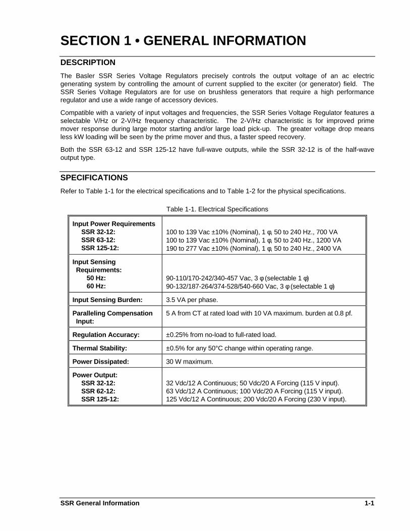
Refer to Table 1-1 for the electrical specifications and to Table 1-2 for the physical specifications.
Table 1-1. Electrical Specifications
Input Power Requirements SSR 32-12: SSR 63-12: SSR 125-12:
100 to 139 Vac ±10% (Nominal), 1 φ, 50 to 240 Hz., 700 VA100 to 139 Vac ±10% (Nominal), 1 φ, 50 to 240 Hz., 1200 VA190 to 277 Vac ±10% (Nominal), 1 φ, 50 to 240 Hz., 2400 VA
Input Sensing Requirements: 50 Hz: 60 Hz:
90-110/170-242/340-457 Vac, 3 φ (selectable 1 φ)90-132/187-264/374-528/540-660 Vac, 3 φ (selectable 1 φ)
Input Sensing Burden: 3.5 VA per phase.
Paralleling Compensation Input:
5 A from CT at rated load with 10 VA maximum. burden at 0.8 pf.
Regulation Accuracy: ±0.25% from no-load to full-rated load.
Thermal Stability: ±0.5% for any 50°C change within operating range.
Power Dissipated: 30 W maximum.
Power Output: SSR 32-12: SSR 62-12: SSR 125-12:
32 Vdc/12 A Continuous; 50 Vdc/20 A Forcing (115 V input).63 Vdc/12 A Continuous; 100 Vdc/20 A Forcing (115 V input).125 Vdc/12 A Continuous; 200 Vdc/20 A Forcing (230 V input).
1-2 SSR General Information
Table 1-1. Electrical Specifications - Continued
Minimum Field Resistance: SSR 32-12: SSR 63-12: SSR 125-12:
2.5 ohms5.0 ohms10.0 ohms
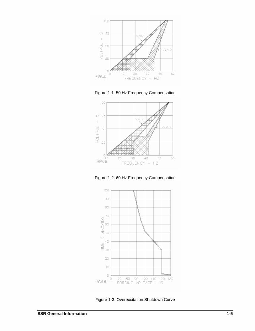
Frequency Compensation: Variable. Frequency roll-off is preset at the factory for 48.5 Hz.(50 Hz. systems) and 58.5 Hz. (60 Hz. systems). Either V/Hz or2 V/Hz can be selected. Refer to Figures 1-1 and1-2.
Voltage Build-Up: From 6 volts residual or more (12 V for the SSR 125-12 only).
Internal Voltage Adjust Range (Minimum):
For 120 V Tap: 90 to 132 Vac;For 240 V Tap: 170 to 264 Vac;For 480 V Tap: 340 to 528 Vac;For 600 V Tap: 540 to 660 Vac.
Overexcitation Protection: Removes excitation if the regulator output is at 95% of ratedforcing voltage for more than 60 seconds or instantaneously (<1second) if output exceeds 130 % of rated forcing voltage. Referto Figure 1-3.
External Voltage AdjustRange:
±10% of nominal.
Optional Circuit Breaker: Rated at 20 A, 277 Vac, 50/60 Hz., with a 5000 A interruptingcapacity.
Table 1-2. Mechanical Specifications
Storage Temperature Range: -40°C (-40°F) to +85°C (+185°F).
Operating TemperatureRange:
-40°C (-40°F) to +70°C (+158°F).
Humidity: The control module is totally protected for humidity andcondensation by encapsulation.
Vibration: Withstands the following: 5 to 26 Hz. at 1.2 G's; 27 to 52 Hz. at 0.036 inch double amplitude; 53 to 1000 Hz. at 5.0 G's.
Shock: Withstands 15 G's in each of three mutually perpendicularplanes.
Weight: 12 lbs. (5.5 kg) net;15 lbs. (7.0 kg) shipping.
Overall Dimensions: Height: Width: Depth:
9.0 inches (230 mm)11.1 inches (281 mm)3.6 inches (93 mm)
Optional Circuit Breaker: Shock: Vibration:
Withstands 100 G's.Withstands 10 G's.
SSR General Information 1-3
Weight: 10 ounces (280 grams) net.
1-4 SSR General Information
ACCESSORIES
The SSR Series Voltage Regulators is designed to be compatible with any of the Basler accessories andequipment listed below:
a. Remote mounted Overexcitation Circuit Breaker (P/N 9 1859 00 014). Refer to Section 2 for moreinformation.
b. VAR/Power Factor Controller (SCP 250)
c. Series Boost Option (SBO 160)
d. Current Transformers (CT2 through CT50)
e. Exciter Diode Monitor (EDM 200)
f. Minimum/Maximum Excitation Limiter (EL 200)
g. Auto-Synchronizer (BE3-25A)
h. Auto-Synchronizer (BE1-25A)
i. Line Drop Compensator (LDC 300)
j. Manual Voltage Control (MVC 112)
k. Low and Medium Power Isolation Transformers. Refer to Table 1-3.
Table 1-3. Transformer Selection
Voltage SSR 32-12 SSR 63-12 SSR 125-12
240/480 BE22207-001 BE22209-001 BE12819-001
600 BE22207-001 BE11050-001 BE22209-001
2400/4160 BE22208-001 BE13487-001 BE12818-001
7200 BE22210-001 BE22136-001 BE22136-001
13800 BE22210-001 BE21327-001 BE21327-001
* Transformers used with the SSR 32-12 are designed to be compatible with the regulator's half-wave dcoutput.
SPIKE SUPPRESSION MODULE
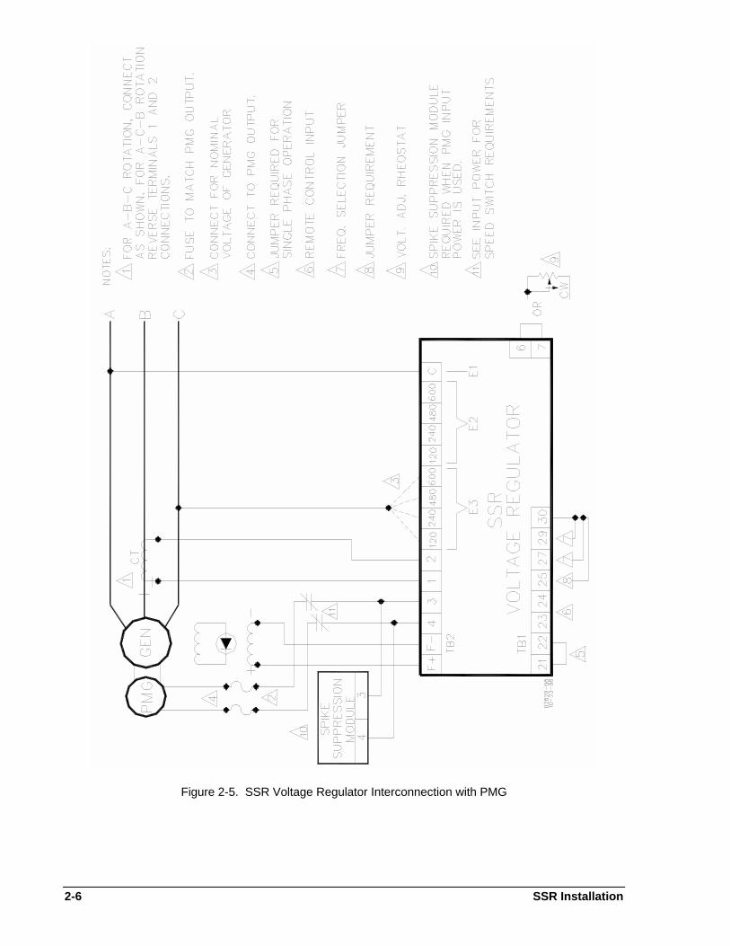
Some higher impedance power sources (such as power isolation transformers and PMG's) may haveenough inductance to cause potentially damaging voltage spikes in the power output stage of the SSRVoltage Regulator. In these cases, Basler Electric recommends the use of the Spike Suppression Modulewhich was supplied with the Regulator to filter out these potentially damaging voltage spikes. Refer toSection 2 for mounting and interconnection instructions.
SSR General Information 1-5
Figure 1-1. 50 Hz Frequency Compensation
Figure 1-2. 60 Hz Frequency Compensation
Figure 1-3. Overexcitation Shutdown Curve

SSR Installation 2-1
SECTION 2 • INSTALLATIONMOUNTING
Voltage Regulator Mounting
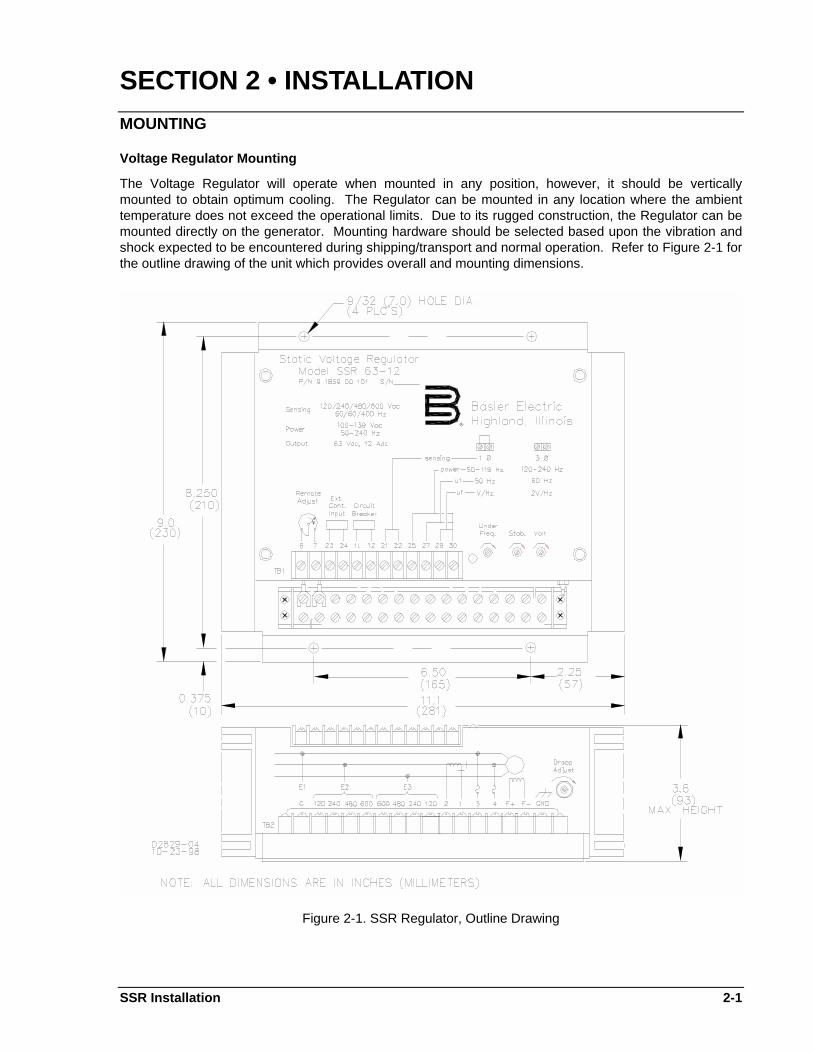
The Voltage Regulator will operate when mounted in any position, however, it should be verticallymounted to obtain optimum cooling. The Regulator can be mounted in any location where the ambienttemperature does not exceed the operational limits. Due to its rugged construction, the Regulator can bemounted directly on the generator. Mounting hardware should be selected based upon the vibration andshock expected to be encountered during shipping/transport and normal operation. Refer to Figure 2-1 forthe outline drawing of the unit which provides overall and mounting dimensions.
Figure 2-1. SSR Regulator, Outline Drawing
2-2 SSR Installation
Spike Suppression Module Mounting
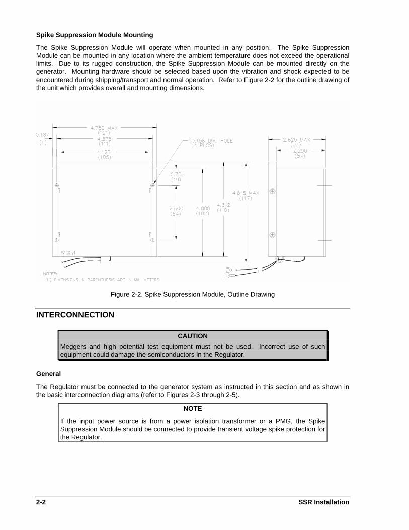
The Spike Suppression Module will operate when mounted in any position. The Spike SuppressionModule can be mounted in any location where the ambient temperature does not exceed the operationallimits. Due to its rugged construction, the Spike Suppression Module can be mounted directly on thegenerator. Mounting hardware should be selected based upon the vibration and shock expected to beencountered during shipping/transport and normal operation. Refer to Figure 2-2 for the outline drawing ofthe unit which provides overall and mounting dimensions.
Figure 2-2. Spike Suppression Module, Outline Drawing
INTERCONNECTION
CAUTION
Meggers and high potential test equipment must not be used. Incorrect use of suchequipment could damage the semiconductors in the Regulator.
General
The Regulator must be connected to the generator system as instructed in this section and as shown inthe basic interconnection diagrams (refer to Figures 2-3 through 2-5).
NOTE
If the input power source is from a power isolation transformer or a PMG, the SpikeSuppression Module should be connected to provide transient voltage spike protection forthe Regulator.
SSR Installation 2-3
Regulator Sensing Connections
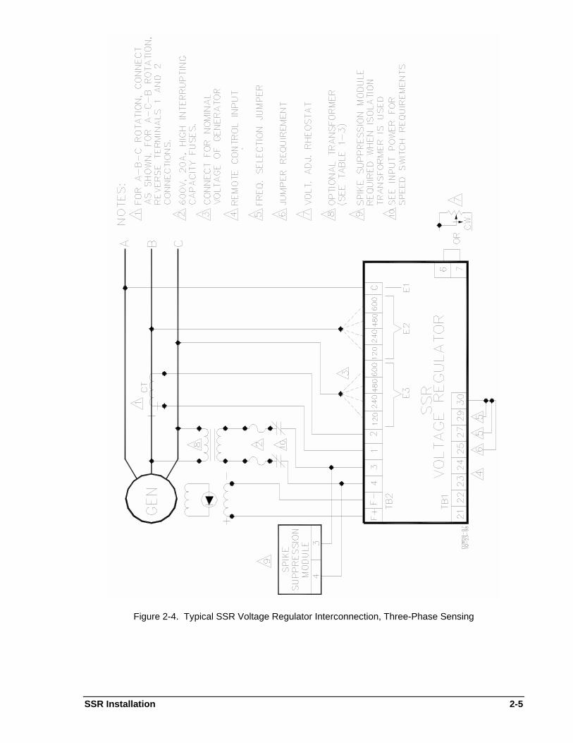
Three-Phase Sensing
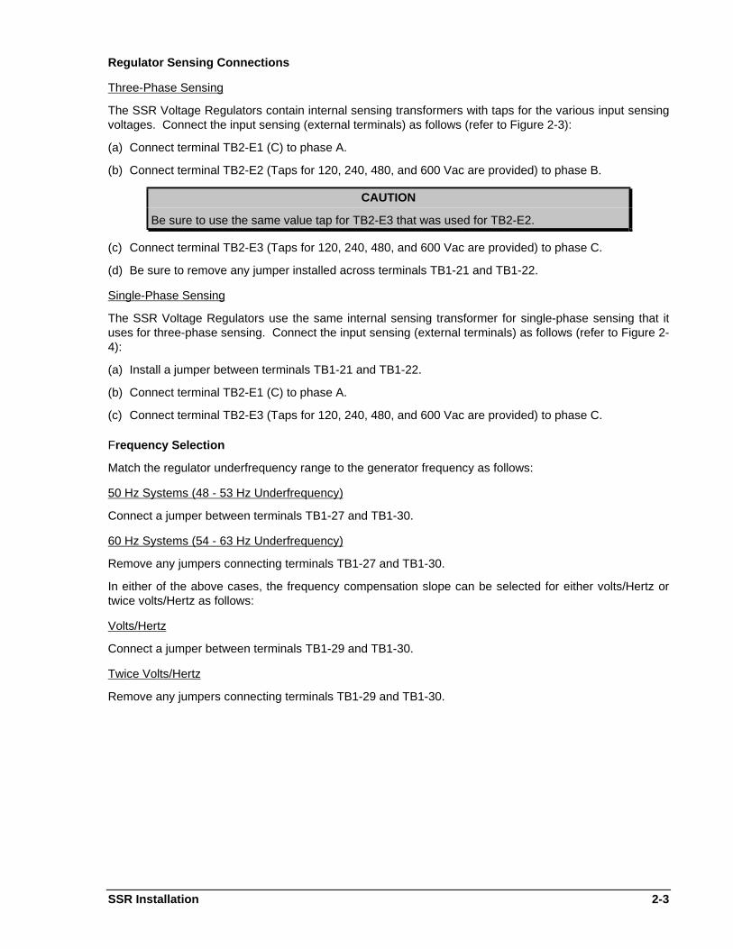
The SSR Voltage Regulators contain internal sensing transformers with taps for the various input sensingvoltages. Connect the input sensing (external terminals) as follows (refer to Figure 2-3):
(a) Connect terminal TB2-E1 (C) to phase A.
(b) Connect terminal TB2-E2 (Taps for 120, 240, 480, and 600 Vac are provided) to phase B.
CAUTION
Be sure to use the same value tap for TB2-E3 that was used for TB2-E2.
(c) Connect terminal TB2-E3 (Taps for 120, 240, 480, and 600 Vac are provided) to phase C.
(d) Be sure to remove any jumper installed across terminals TB1-21 and TB1-22.
Single-Phase Sensing
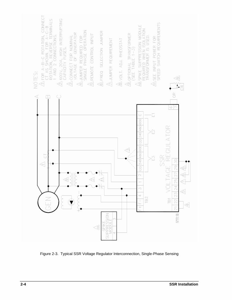
The SSR Voltage Regulators use the same internal sensing transformer for single-phase sensing that ituses for three-phase sensing. Connect the input sensing (external terminals) as follows (refer to Figure 2-4):
(a) Install a jumper between terminals TB1-21 and TB1-22.
(b) Connect terminal TB2-E1 (C) to phase A.
(c) Connect terminal TB2-E3 (Taps for 120, 240, 480, and 600 Vac are provided) to phase C.
Frequency Selection
Match the regulator underfrequency range to the generator frequency as follows:
50 Hz Systems (48 - 53 Hz Underfrequency)
Connect a jumper between terminals TB1-27 and TB1-30.
60 Hz Systems (54 - 63 Hz Underfrequency)
Remove any jumpers connecting terminals TB1-27 and TB1-30.
In either of the above cases, the frequency compensation slope can be selected for either volts/Hertz ortwice volts/Hertz as follows:
Volts/Hertz
Connect a jumper between terminals TB1-29 and TB1-30.
Twice Volts/Hertz
Remove any jumpers connecting terminals TB1-29 and TB1-30.
2-4 SSR Installation
Figure 2-3. Typical SSR Voltage Regulator Interconnection, Single-Phase Sensing
SSR Installation 2-5
Figure 2-4. Typical SSR Voltage Regulator Interconnection, Three-Phase Sensing
2-6 SSR Installation
Figure 2-5. SSR Voltage Regulator Interconnection with PMG
SSR Installation 2-7
Field Power Connection
(1) Be sure to observe polarity and connect the field leads to terminals TB2-F+ and TB2-F-.
(2) The dc resistance of the field to which the Regulator is connected (terminals TB2-F+ and TB2-F-)must be equal to, or greater than that specified in Table 1-1. If the resistance is less than thespecified minimum, a resistor must be added in series with the field. This resistor value plus the fieldresistance, must be equal to or greater than the minimum field resistance.
Input Power
(1) The input power connected to terminals TB2-3 and TB2-4 should be fused and may be taken from anygenerator lines that provide the correct voltage (line-to-line or line-to-neutral) as specified in Table 1-1. If line-to-neutral is used with a grounded neutral, it is strongly recommended that a power isolationtransformer be used to limit the possibility of a ground loop. The phase relationship on this input tothe other inputs is not important.
(2) When the generator output voltage does not match the values given in Table 1-1, a power transformermust be used to match the generator output to the Regulator input (refer to Table 1-3 for propertransformer selection). If excessive voltage is applied to the Regulator, the Regulator will bedamaged.
CAUTION
Without the use of a power isolation transformer, any ground in the field circuit andanother ground in the generator output could result in Regulator failure.
NOTE
On prime mover applications that require a long time to reach rated RPM, a speed switchsetting should be coordinated such that input voltage applied to the SSR is above theSSR minimum residual build-up level. The minimum residual build-up level is 6 Vac forthe SSR32-12 and SSR63-12, and 12 Vac for the SSR125-12.
(3) If the field or field flashing circuit is grounded, a power transformer must be used to isolate theRegulator input from ground.
(4) If the SSR is powered directly from a 50 Hz or 60 Hz generator output (as in Figures 2-3 and 2-4),install a jumper between terminals TB1-25 and TB1-30. If the SSR is powered from a special source,such as a PMG (as in Figure 2-5), the frequency of the incoming power must be considered. If thisfrequency is less than 120 Hz, install a jumper between terminals TB1-25 and TB1-30. If the inputpower frequency is between 120 Hz and 240 Hz, then remove any jumpers connecting terminals TB1-25 and TB1-30.
External Control Input
When using an external control device such as a VAR/Power Factor Controller (SCP 250), Auto-Synchronizer (BE1-25A or BE3-25A), and/or a Minimum/Maximum Excitation Limiter (EL 200), thenconnect them in series with terminals TB1-23 and TB1-24. Refer to the accessory item manuals forproper connection.
Remote Voltage Adjust Rheostat
When using an external voltage adjust rheostat, connect the rheostat to terminals TB1-6 and TB1-7. Usethe potentiometer supplied with the Regulator (as a loose item) or replace it with any 5 kW, 2 Wattrheostat/potentiometer. If using only the internal voltage adjust, install a jumper across terminals TB1-6and TB1-7. If shielding of the wiring is required due to its location in a high noise environment, connectthe shield to terminal 30 of the SSR. If connected anyplace else, the shielding will not have any effect.
2-8 SSR Installation
Parallel Compensation
(1) When it is required to operate the generator in parallel, a 25 VA current transformer (CT) is required. The CT is connected into the generator line and should deliver from 3 to 5 amperes secondary currentat rated load to the Regulator terminals, TB2-1 and TB2-2.
(2) The phase relationship of the CT signal to the Regulator sensing input must be correct or the systemwill not parallel properly. For three-phase sensing, the CT must be installed in the line supplying thesensing voltage to terminal TB2-E2 (phase B). For single-phase sensing, the CT must be installed inthe line that does not supply sensing to the Regulator (phase B).
Reactive Droop Compensation
(1) For reactive droop compensation, connect the Regulator to the CT as shown by Figures 2-3 and 2-4.
(2) A unit/parallel switch shorts the parallel CT secondary to prevent any droop signal from being injectedinto the regulating system during single-unit operation. The switch may not be required on paralleldroop compensation applications where a voltage drop is not objectionable.
Reactive Differential (Cross-Current) Compensation
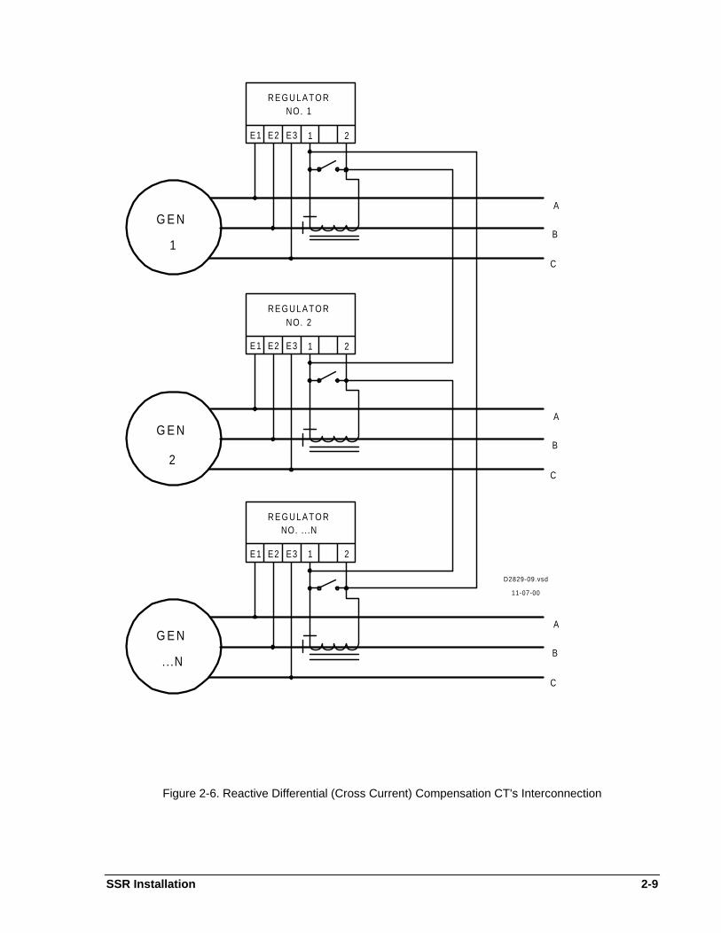
(1) On parallel reactive differential (cross-current) compensation applications, a contact should be used toshort out the paralleling CT secondary when that generator is not paralleled to the bus. If the switch isnot used, a voltage droop will be introduced into the system. This is due to the unloaded generatorparallel CT not supplying a compensated signal, but allowing a voltage drop to occur across it. Lack ofthis shorting contact will also cause the voltage of the oncoming generator to fluctuate prior toparalleling. Ideally, this contact is an auxiliary of the circuit breaker contractor (52 device) that openswhen the breaker is closed.
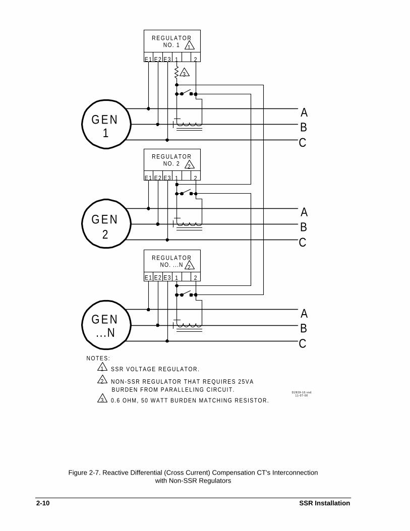
(2) For reactive differential (cross-current) compensation, refer to Figure 2-6 when only SSR's are beingused. If SSR's and non-SSR regulators are used, refer to Figure 2-7. First connect each CT to itsrespective Regulator. Then connect the end of the first CT to the start of the second CT, the end ofthe second CT to the start of the third, etc. Continue until all of the CT's are connected in series. Thefinal step will be to connect the end of the last CT to the start of the first CT.
(3) Reactive differential compensation should not be used with generators in parallel with the utility or anyinfinite bus. If the system will be paralleled with a source not in the loop, a switching circuit must beused to convert the system to a reactive droop compensation system by opening the loop at any point.
Overexcitation Circuit Breaker
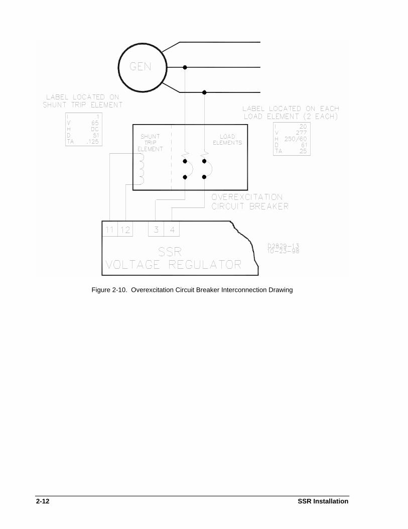
An optional Overexcitation Circuit Breaker is available which will perform three functions as follows (referto Figures 2-8 through 2-10):
(1) The Circuit Breaker can be operated manually to perform as an On/Off switch to apply or remove acpower and replaces the input power fuses connected to terminals TB2-3 and TB2-4.
(2) The Circuit Breaker will respond to a special signal from the overexcitation circuit in the Regulator. This signal will open the Circuit Breaker if the field voltage remains after the internal overexcitationcircuit has tripped and thus provide a back-up to the Regulator circuitry. This condition could arise asa result of component failure within the regulator.
(3) In 50/60 Hz applications, the Circuit Breaker provides overcurrent protection. For higher frequencypower sources such as a PMG, fuses must be used to provide proper overcurrent protection.
SSR Installation 2-9
G E NA
B
C
R E G U L A T O RNO. 1
E1 E2 E3 1 2
21E3E2E1
NO. 2R E G U L A T O R
C
B
A
G E N
21E3E2E1
NO. . . .NR E G U L A T O R
C
B
AG E N
...N
1
2
D2829-09.vsd
11-07-00
Figure 2-6. Reactive Differential (Cross Current) Compensation CT's Interconnection
2-10 SSR Installation
G E N ABC
R E G U L A T O RNO. 1
E1 E2 E3 1 2
21E3E2E1
NO. 2R E G U L A T O R
CBA
G E N
21E3E2E1
NO. . . .NR E G U L A T O R
CBAG E N
...N
1
2
2
2
1
3
N O T E S :
1 S S R V O L T A G E R E G U L A T O R .
N O N - S S R R E G U L A T O R T H A T R E Q U I R E S 2 5 V A2BURDEN FROM PARALLEL ING C IRCUIT .
0 .6 OHM, 50 WATT BURDEN MATCHING RESISTOR.3D2829-10.vsd
11-07-00
Figure 2-7. Reactive Differential (Cross Current) Compensation CT's Interconnectionwith Non-SSR Regulators
SSR Installation 2-11
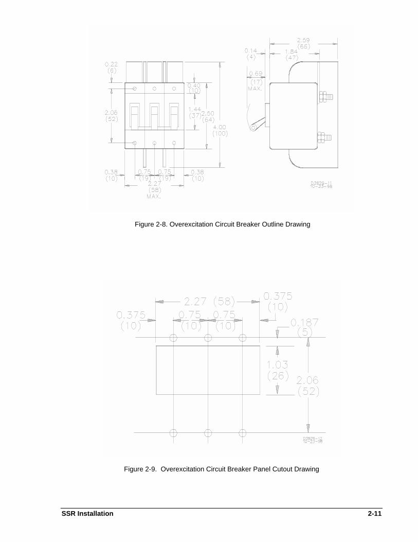
Figure 2-8. Overexcitation Circuit Breaker Outline Drawing
Figure 2-9. Overexcitation Circuit Breaker Panel Cutout Drawing
2-12 SSR Installation
Figure 2-10. Overexcitation Circuit Breaker Interconnection Drawing
SSR Operation 3-1
SECTION 3 • OPERATIONFRONT PANEL CONTROLS AND INDICATORS
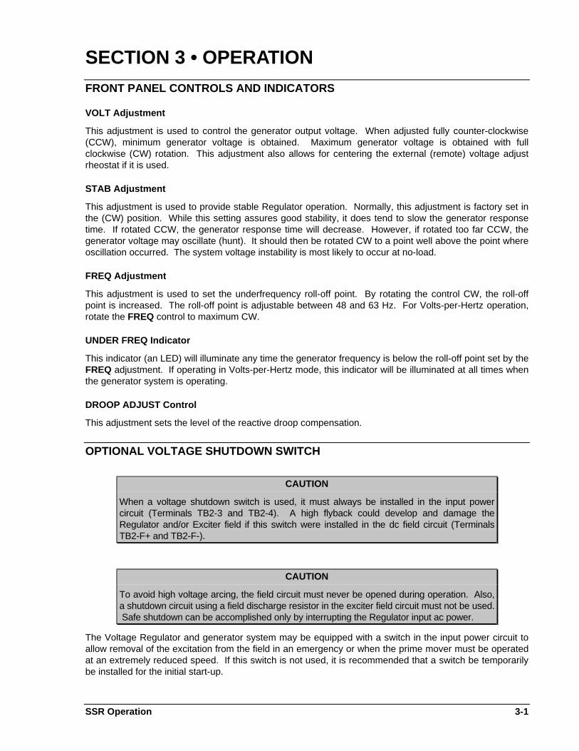
VOLT Adjustment
This adjustment is used to control the generator output voltage. When adjusted fully counter-clockwise(CCW), minimum generator voltage is obtained. Maximum generator voltage is obtained with fullclockwise (CW) rotation. This adjustment also allows for centering the external (remote) voltage adjustrheostat if it is used.
STAB Adjustment
This adjustment is used to provide stable Regulator operation. Normally, this adjustment is factory set inthe (CW) position. While this setting assures good stability, it does tend to slow the generator responsetime. If rotated CCW, the generator response time will decrease. However, if rotated too far CCW, thegenerator voltage may oscillate (hunt). It should then be rotated CW to a point well above the point whereoscillation occurred. The system voltage instability is most likely to occur at no-load.
FREQ Adjustment
This adjustment is used to set the underfrequency roll-off point. By rotating the control CW, the roll-offpoint is increased. The roll-off point is adjustable between 48 and 63 Hz. For Volts-per-Hertz operation,rotate the FREQ control to maximum CW.
UNDER FREQ Indicator
This indicator (an LED) will illuminate any time the generator frequency is below the roll-off point set by theFREQ adjustment. If operating in Volts-per-Hertz mode, this indicator will be illuminated at all times whenthe generator system is operating.
DROOP ADJUST Control
This adjustment sets the level of the reactive droop compensation.
OPTIONAL VOLTAGE SHUTDOWN SWITCH
CAUTION
When a voltage shutdown switch is used, it must always be installed in the input powercircuit (Terminals TB2-3 and TB2-4). A high flyback could develop and damage theRegulator and/or Exciter field if this switch were installed in the dc field circuit (TerminalsTB2-F+ and TB2-F-).
CAUTION
To avoid high voltage arcing, the field circuit must never be opened during operation. Also,a shutdown circuit using a field discharge resistor in the exciter field circuit must not be used. Safe shutdown can be accomplished only by interrupting the Regulator input ac power.
The Voltage Regulator and generator system may be equipped with a switch in the input power circuit toallow removal of the excitation from the field in an emergency or when the prime mover must be operatedat an extremely reduced speed. If this switch is not used, it is recommended that a switch be temporarilybe installed for the initial start-up.
3-2 SSR Operation
INITIAL OPERATION
Preliminary Instructions
Verify that all wiring is properly and securely connected. Refer to Section 2.
System Check-out
Perform the following steps to ensure the proper operation of the Regulator during initial operation:
(1) Start the prime mover and bring up to rated speed. If a voltage shutdown switch is used, close theswitch to apply excitation. When this switch is not used, generator voltage will build up automatically.
(2) Verify generator voltage. Note that any of the following conditions may occur:
Overvoltage
If this condition occurs, open the shutdown switch and stop the prime mover. Determine the cause of theovervoltage. If necessary, refer to the troubleshooting chart in Section 4.
No Voltage Build-up
If this condition occurs, field flashing may be required. Refer to the following sub-section Flashing.
Undervoltage
If this condition occurs, adjust the VOLT control. If not corrected, refer to the troubleshooting chart inSection 4.
Voltage Builds Up and Then Collapses
If this condition occurs, stop the prime mover and determine the cause by referring to the troubleshootingchart in Section 4.
Oscillating Voltage
If this condition occurs, rotate the front panel STAB adjustment to correct. If the voltage continues tooscillate and the STAB control has no effect, refer to the troubleshooting chart in Section 4.
(3) Adjust the front panel VOLT control for nominal generator output.
(4) Apply load to the generator.
(5) Verify that the voltage regulation is within ±0.25%. If not, refer to the troubleshooting chart in Section4.
(6) Alternately remove and apply the load to determine if the generator voltage is stable.
(7) If an underfrequency setting other than the factory pre-set is desired, proceed as follows:
(a) Lower the generator frequency (speed) to the desired underfrequency value.
(b) Rotate the front panel FREQ adjustment until the front panel UNDER FREQ indicator (LED) isilluminated.
(c) Return the generator frequency (speed) to its nominal value.
SSR Operation 3-3
FIELD FLASHING
CAUTION
Do not attempt to flash the machine when it is rotating.
When the Voltage Regulator is operated with the generator for the first time, the polarity of residualmagnetism may not be correct or of sufficient magnitude. If the generator does not build up after start-up,check for 6 volts or more residual at the Regulator terminals TB2-3 and TB2-4. If the voltage is below 6volts, shut down the prime mover and proceed as follows:
a. With the prime mover at rest, apply a dc source (non-grounded) of not more than 12 Vdc, to terminals"F+" (positive) and "F-" (negative) while observing polarity, in series with a limiting resistor of 25 - 30ohms.
b. Allow approximately 3 seconds before removing the dc source.
c. With the Voltage Regulator power input disconnected (terminals TB2-3 and TB2-4), start the primemover and measure the voltage at the generator terminals. If the generator output is less than 6 volts,repeat steps a. and b. If the voltage is greater than 6 volts, voltage build-up should occur. Stop theprime mover and reconnect the Regulator input power.
PARALLEL OPERATION
The following paragraphs describe the procedures to be followed when operating two or more generatorsin parallel. In order to ensure proper operation, the following requirements must be met:
(1) The voltage regulating systems must cause the generators to share the total kVAR load,
and
(2) The speed governing system must make the generators share the total kW load.
Preliminary Instructions
It is essential that the paralleling signal at terminals TB2-1 and TB2-2 of the regulator have the properphase relationship with that of the sensing voltages at terminals TB2-E1, TB2-E2, and TB2-E3. Verify thatthese connections are made as shown by Figure 2-2. If reactive differential (cross-current) compensationis desired, the paralleling CT's must be connected as described in Section 2. A CT must be selectedwhich will furnish 3 to 5 amperes at the rated generator load current.
Preliminary Operation
Before attempting to parallel two or more generators, it is recommended that the individual generators betested to verify that the paralleling features function properly. Test as follows:
(1) Place each generator in operation in accordance with initial operation instructions.
(2) Verify that the paralleling CT secondary is not shorted. (Unit/Parallel switch in Parallel position.)
(3) Verify that the front panel DROOP ADJUST control is adjusted for maximum droop.
(4) Apply 25% to 100% unity power factor load to the generator under test. The generator voltage shouldnot change more than 1%.
(5) Apply 25% to 100% 0.8 pf inductive load to the generator under test. The generator voltage shoulddroop from 2% to 6% with the reactive load. If the voltage rises instead of drooping, reverse the CTsensing leads.
(6) Verify that the voltage and speed do not drift or jump erratically.
3-4 SSR Operation
Conditions Necessary for Paralleling
In order to prevent damage to the generator and/or prime mover, paralleling should be attempted onlywhen the generator speeds (frequencies) are equal and at the instant when the generator voltages areequal. That is, they have the same phase sequence of voltage and the voltages are in phase.
Paralleling Operation
The following instructions describe the procedures for paralleling two or more generators. If using anauto-synchronizer (such as the Basler BE1-25A or BE3-25A) than all adjustments and the breaker closureare automatically performed by the auto-synchronizer.
(1) Start generator No. 1 and verify that the bus is dead.
(2) Close the breaker connecting generator No. 1 to the bus.
(3) Adjust the generator voltage and frequency to nominal.
(4) Apply the load. (If possible, the load should be at least 10% or more of the generator kW rating.)
(5) Start generator No. 2 and adjust the output to nominal.
(6) Adjust generator No. 2's speed slightly higher than that of No. 1's. Speeds must be within 0.1 Hz(10 second rotation of synchroscope through 360°).
(7) At zero phase angle between the generator and bus, close the breaker for the No. 2 generator andimmediately read the ammeter for No. 2. The reading should be well within the generator rating andthe operation stable. If not, shut down the system and troubleshoot.
(8) Adjust the speed of No. 2 to the point where each set is carrying the desired share of the load.
(9) Adjust the voltage of No. 2 until the ammeter reading (of both generators) are near minimum.
(10) If kVAR meters are available, adjust the front panel DROOP ADJUST on Regulator No. 2 for anequal kVAR reading.
(11) If the generators are equipped with power factor meters instead of kW meters, alternately adjust thespeed and droop of No. 2 until the ammeter readings are proportional and the power factor readingsare equal.
NOTE
For best results, final adjustments should be made with a full load on the bus.
(12) With a full load applied, readjust the speed and voltage on No. 2 until the desired load division isobtained.
SSR Maintenance 4-1
SECTION 4 • MAINTENANCEPREVENTIVE MAINTENANCE
The only preventive maintenance required on the SSR Series Voltage Regulators is to periodically checkthat the connections between the Regulator and system are clean and tight and that the Regulator coolingfins and housing are free from accumulations of dirt and dust.
CORRECTIVE MAINTENANCE
The SSR Series Voltage Regulators are designed for ease of repair by the replacement of major parts,such as the transformers, power module, or electronics module. Refer to Section 5 for part numbers.
WARRANTY AND REPAIR SERVICE
The Basler SSR Series Voltage Regulators are warranted against defective material and workmanship for18 months from the date of shipment from our factory. Units submitted for warranty repair should bereturned to the factory in Highland, Illinois, freight prepaid, with a complete description of the installationand the reported problem. Pre-arrangement with either the nearest Basler Sales Office or with the factorywill assure the fastest possible turn around time.
TROUBLESHOOTING
The more common generator system malfunctions and the appropriate repair procedures are listed inTable 4-1.
OPERATIONAL TESTING
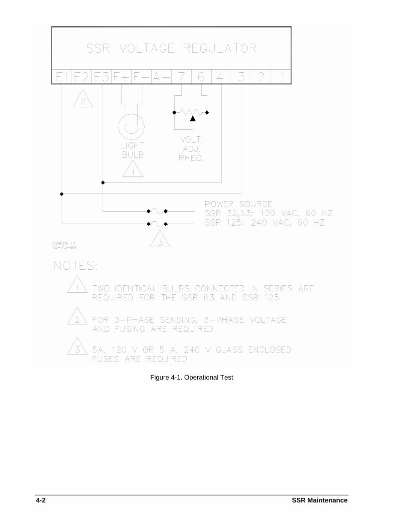
To test the SSR Voltage Regulator, refer to Figure 4-1 and proceed as follows:
a. Adjust the front panel STAB control fully counter-clockwise (CCW).
b. Connect the circuit as shown in Figure 4-1. The light bulb should be a 120 V type of not more than300 W).
c. Adjust the Voltage Adjust Rheostat for maximum resistance.
d. Connect the regulator to a power source. Note that the light bulbs may flash momentarily.
e. Slowly rotate the Voltage Adjust Rheostat toward minimum resistance. The light should reach fullbrilliance before minimum resistance is attained. (If the light does not illuminate, adjust the front panelVOLT control.)
f. At the regulating point, a small change in the Voltage Adjust Rheostat should turn the light on or off.
NOTE
If the light bulb(s) do not illuminate, the regulator is defective.
g. This test may not reveal a stability problem. However, rotating the front panel STAB adjustmentshould affect the bulb's turn on/turn off time.
4-2 SSR Maintenance
Figure 4-1. Operational Test
SSR Maintenance 4-3
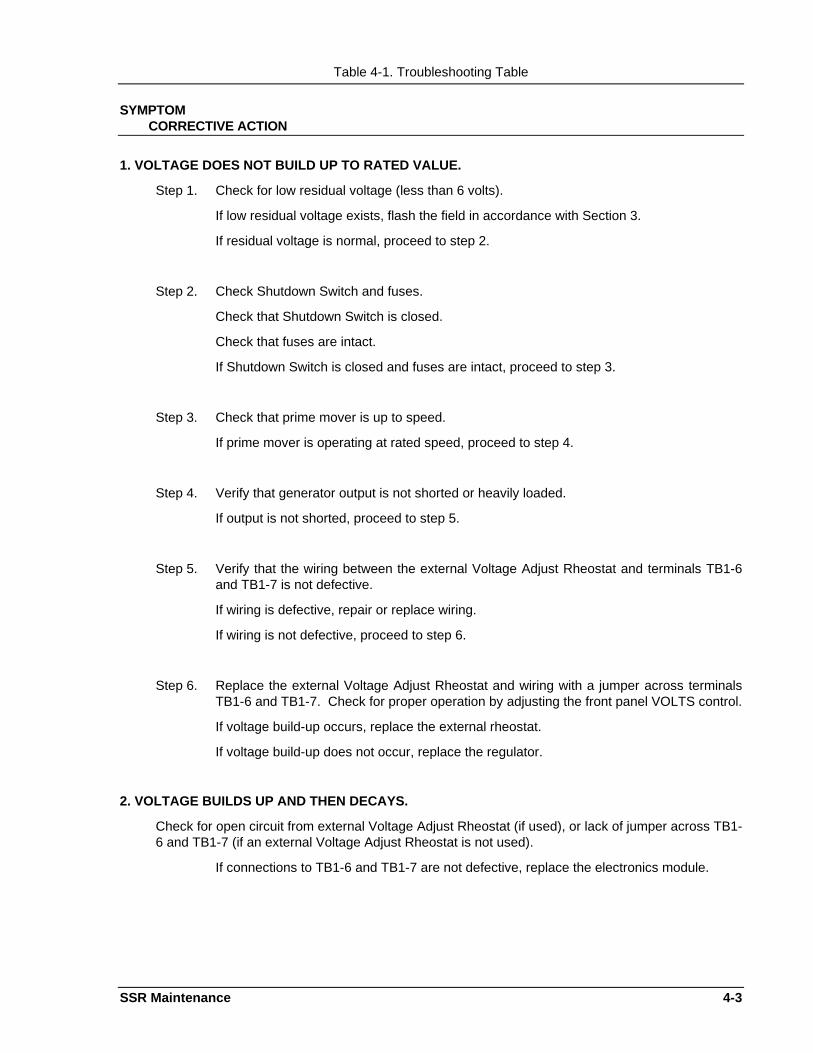
Table 4-1. Troubleshooting Table
SYMPTOMCORRECTIVE ACTION
1. VOLTAGE DOES NOT BUILD UP TO RATED VALUE.
Step 1. Check for low residual voltage (less than 6 volts).
If low residual voltage exists, flash the field in accordance with Section 3.
If residual voltage is normal, proceed to step 2.
Step 2. Check Shutdown Switch and fuses.
Check that Shutdown Switch is closed.
Check that fuses are intact.
If Shutdown Switch is closed and fuses are intact, proceed to step 3.
Step 3. Check that prime mover is up to speed.
If prime mover is operating at rated speed, proceed to step 4.
Step 4. Verify that generator output is not shorted or heavily loaded.
If output is not shorted, proceed to step 5.
Step 5. Verify that the wiring between the external Voltage Adjust Rheostat and terminals TB1-6and TB1-7 is not defective.
If wiring is defective, repair or replace wiring.
If wiring is not defective, proceed to step 6.
Step 6. Replace the external Voltage Adjust Rheostat and wiring with a jumper across terminalsTB1-6 and TB1-7. Check for proper operation by adjusting the front panel VOLTS control.
If voltage build-up occurs, replace the external rheostat.
If voltage build-up does not occur, replace the regulator.
2. VOLTAGE BUILDS UP AND THEN DECAYS.
Check for open circuit from external Voltage Adjust Rheostat (if used), or lack of jumper across TB1-6 and TB1-7 (if an external Voltage Adjust Rheostat is not used).
If connections to TB1-6 and TB1-7 are not defective, replace the electronics module.
4-4 SSR Maintenance
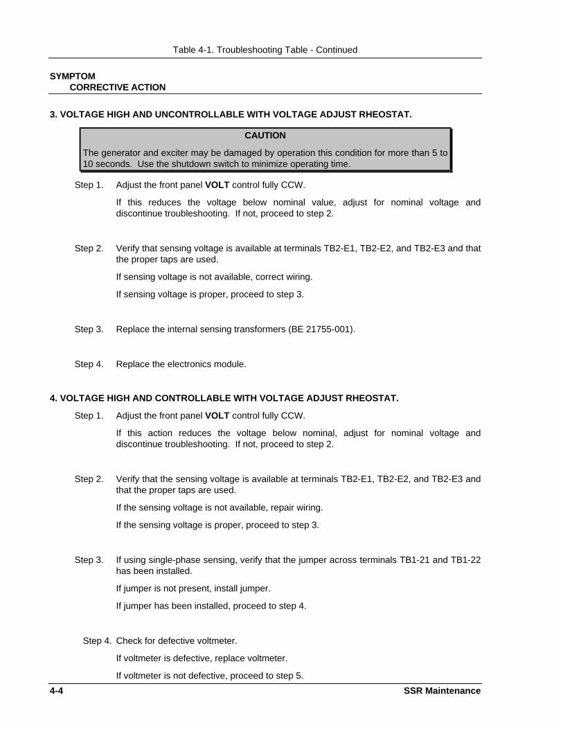
Table 4-1. Troubleshooting Table - Continued
SYMPTOMCORRECTIVE ACTION
3. VOLTAGE HIGH AND UNCONTROLLABLE WITH VOLTAGE ADJUST RHEOSTAT.
CAUTION
The generator and exciter may be damaged by operation this condition for more than 5 to10 seconds. Use the shutdown switch to minimize operating time.
Step 1. Adjust the front panel VOLT control fully CCW.
If this reduces the voltage below nominal value, adjust for nominal voltage anddiscontinue troubleshooting. If not, proceed to step 2.
Step 2. Verify that sensing voltage is available at terminals TB2-E1, TB2-E2, and TB2-E3 and thatthe proper taps are used.
If sensing voltage is not available, correct wiring.
If sensing voltage is proper, proceed to step 3.
Step 3. Replace the internal sensing transformers (BE 21755-001).
Step 4. Replace the electronics module.
4. VOLTAGE HIGH AND CONTROLLABLE WITH VOLTAGE ADJUST RHEOSTAT.
Step 1. Adjust the front panel VOLT control fully CCW.
If this action reduces the voltage below nominal, adjust for nominal voltage anddiscontinue troubleshooting. If not, proceed to step 2.
Step 2. Verify that the sensing voltage is available at terminals TB2-E1, TB2-E2, and TB2-E3 andthat the proper taps are used.
If the sensing voltage is not available, repair wiring.
If the sensing voltage is proper, proceed to step 3.
Step 3. If using single-phase sensing, verify that the jumper across terminals TB1-21 and TB1-22has been installed.
If jumper is not present, install jumper.
If jumper has been installed, proceed to step 4.
Step 4. Check for defective voltmeter.
If voltmeter is defective, replace voltmeter.
If voltmeter is not defective, proceed to step 5.

SSR Maintenance 4-5
4-6 SSR Maintenance
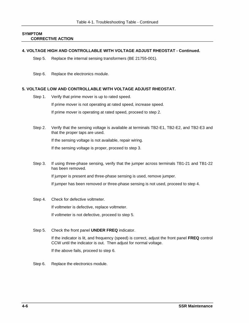
Table 4-1. Troubleshooting Table - Continued
SYMPTOMCORRECTIVE ACTION
4. VOLTAGE HIGH AND CONTROLLABLE WITH VOLTAGE ADJUST RHEOSTAT - Continued.
Step 5. Replace the internal sensing transformers (BE 21755-001).
Step 6. Replace the electronics module.
5. VOLTAGE LOW AND CONTROLLABLE WITH VOLTAGE ADJUST RHEOSTAT.
Step 1. Verify that prime mover is up to rated speed.
If prime mover is not operating at rated speed, increase speed.
If prime mover is operating at rated speed, proceed to step 2.
Step 2. Verify that the sensing voltage is available at terminals TB2-E1, TB2-E2, and TB2-E3 andthat the proper taps are used.
If the sensing voltage is not available, repair wiring.
If the sensing voltage is proper, proceed to step 3.
Step 3. If using three-phase sensing, verify that the jumper across terminals TB1-21 and TB1-22has been removed.
If jumper is present and three-phase sensing is used, remove jumper.
If jumper has been removed or three-phase sensing is not used, proceed to step 4.
Step 4. Check for defective voltmeter.
If voltmeter is defective, replace voltmeter.
If voltmeter is not defective, proceed to step 5.
Step 5. Check the front panel UNDER FREQ indicator.
If the indicator is lit, and frequency (speed) is correct, adjust the front panel FREQ controlCCW until the indicator is out. Then adjust for normal voltage.
If the above fails, proceed to step 6.
Step 6. Replace the electronics module.
SSR Maintenance 4-7
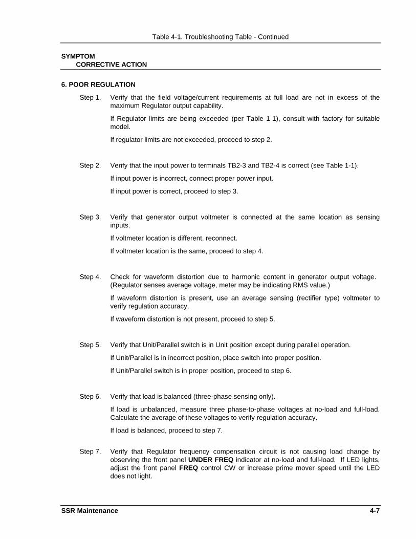
Table 4-1. Troubleshooting Table - Continued
SYMPTOMCORRECTIVE ACTION
6. POOR REGULATION
Step 1. Verify that the field voltage/current requirements at full load are not in excess of themaximum Regulator output capability.
If Regulator limits are being exceeded (per Table 1-1), consult with factory for suitablemodel.
If regulator limits are not exceeded, proceed to step 2.
Step 2. Verify that the input power to terminals TB2-3 and TB2-4 is correct (see Table 1-1).
If input power is incorrect, connect proper power input.
If input power is correct, proceed to step 3.
Step 3. Verify that generator output voltmeter is connected at the same location as sensinginputs.
If voltmeter location is different, reconnect.
If voltmeter location is the same, proceed to step 4.
Step 4. Check for waveform distortion due to harmonic content in generator output voltage. (Regulator senses average voltage, meter may be indicating RMS value.)
If waveform distortion is present, use an average sensing (rectifier type) voltmeter toverify regulation accuracy.
If waveform distortion is not present, proceed to step 5.
Step 5. Verify that Unit/Parallel switch is in Unit position except during parallel operation.
If Unit/Parallel is in incorrect position, place switch into proper position.
If Unit/Parallel switch is in proper position, proceed to step 6.
Step 6. Verify that load is balanced (three-phase sensing only).
If load is unbalanced, measure three phase-to-phase voltages at no-load and full-load.Calculate the average of these voltages to verify regulation accuracy.
If load is balanced, proceed to step 7.
Step 7. Verify that Regulator frequency compensation circuit is not causing load change byobserving the front panel UNDER FREQ indicator at no-load and full-load. If LED lights,adjust the front panel FREQ control CW or increase prime mover speed until the LEDdoes not light.
4-8 SSR Maintenance
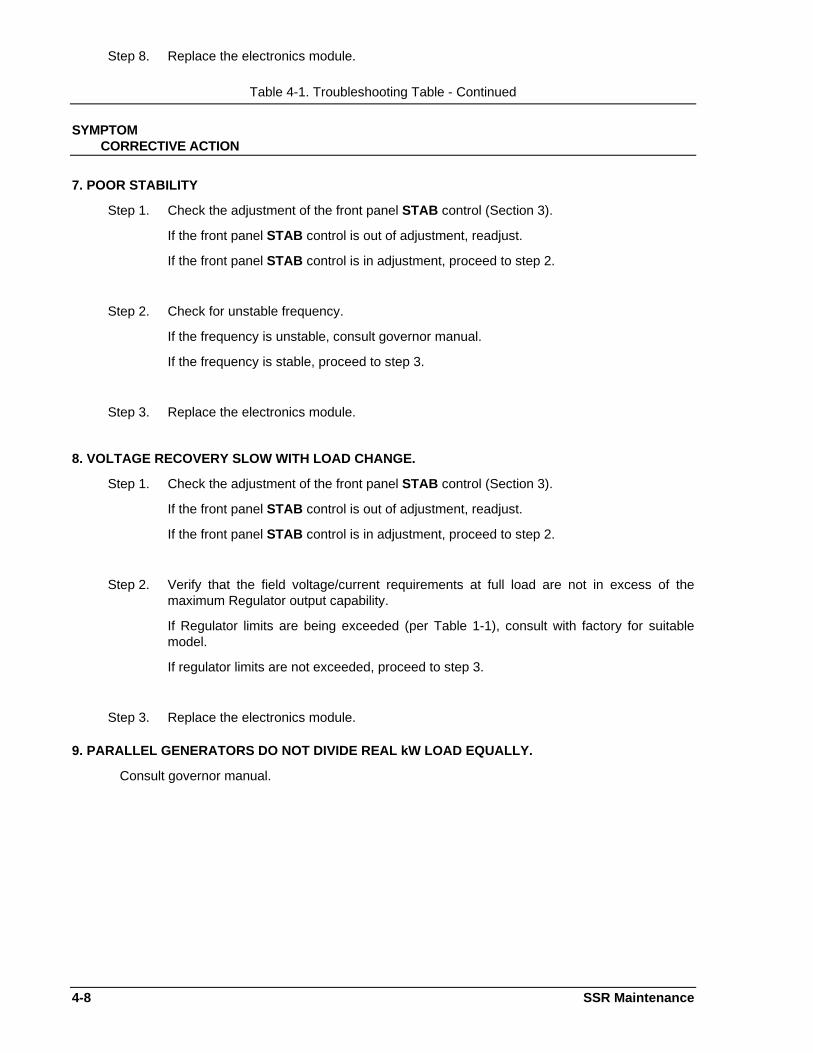
Step 8. Replace the electronics module.
Table 4-1. Troubleshooting Table - Continued
SYMPTOMCORRECTIVE ACTION
7. POOR STABILITY
Step 1. Check the adjustment of the front panel STAB control (Section 3).
If the front panel STAB control is out of adjustment, readjust.
If the front panel STAB control is in adjustment, proceed to step 2.
Step 2. Check for unstable frequency.
If the frequency is unstable, consult governor manual.
If the frequency is stable, proceed to step 3.
Step 3. Replace the electronics module.
8. VOLTAGE RECOVERY SLOW WITH LOAD CHANGE.
Step 1. Check the adjustment of the front panel STAB control (Section 3).
If the front panel STAB control is out of adjustment, readjust.
If the front panel STAB control is in adjustment, proceed to step 2.
Step 2. Verify that the field voltage/current requirements at full load are not in excess of themaximum Regulator output capability.
If Regulator limits are being exceeded (per Table 1-1), consult with factory for suitablemodel.
If regulator limits are not exceeded, proceed to step 3.
Step 3. Replace the electronics module.
9. PARALLEL GENERATORS DO NOT DIVIDE REAL kW LOAD EQUALLY.
Consult governor manual.
SSR Maintenance 4-9
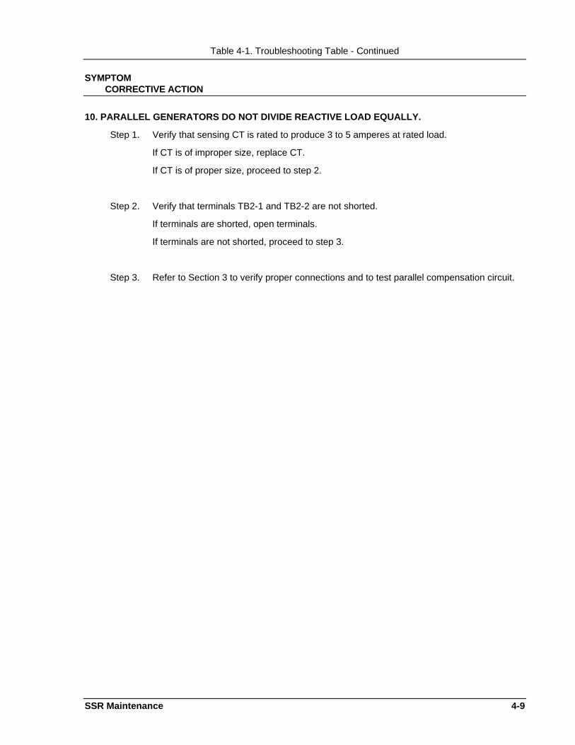
Table 4-1. Troubleshooting Table - Continued
SYMPTOMCORRECTIVE ACTION
10. PARALLEL GENERATORS DO NOT DIVIDE REACTIVE LOAD EQUALLY.
Step 1. Verify that sensing CT is rated to produce 3 to 5 amperes at rated load.
If CT is of improper size, replace CT.
If CT is of proper size, proceed to step 2.
Step 2. Verify that terminals TB2-1 and TB2-2 are not shorted.
If terminals are shorted, open terminals.
If terminals are not shorted, proceed to step 3.
Step 3. Refer to Section 3 to verify proper connections and to test parallel compensation circuit.


SSR Replacement Parts 5-1
SECTION 5 • REPLACEMENT PARTSGENERAL
The following list (Table 5-1) describes the components of the SSR Series of Voltage Regulators that havemaintenance significance. When ordering parts from Basler Electric Company, be sure to specify theRegulator model and part number and the Basler component part number, quantity, and description. Unless otherwise specified, all components are interchangeable.
Table 5-2 provides a Model Number to Part Number Cross-Reference list of the SSR regulators.
Table 5-1. Replacement Parts
Basler Part Number Qty Description
9 1859 01 100 1 Printed Circuit Board Assembly (Model SSR 32-12 Only)
9 1859 01 101 1 Printed Circuit Board Assembly (Model SSR 63-12 Only)
9 1859 01 102 1 Printed Circuit Board Assembly (Model SSR 125-12 Only)
19781 1 Resistor, Variable, 15 ohms, 12.5 watts
19364 2 Power Module (SSR 63-12 and SSR 125-12 Only)
19763 1 SCR Module (SSR 32-12 Only)
19764 1 Diode Module (SSR 32-12 Only)
BE22352-001 1 Transformer
BE21600-001 1 Transformer
BE21755-001 1 Transformer
BE21756-001 1 Transformer
02682 1 Potentiometer, 5 kohms, 2 watts
9 2615 00 100 1 Spike Suppression Module (Models SSR32-12 & SSR63-12Only)
9 2615 00 101 1 Spike Suppression Module (Model SSR125-12 Only)
Table 5-2. Part Number to Model Number Cross-Reference List
Model Number Part Number
SSR 32-12 9 1859 00 100
SSR 63-12 9 1859 00 101
SSR 125-12 9 1859 00 102

SSR Manual Change Information 6-1
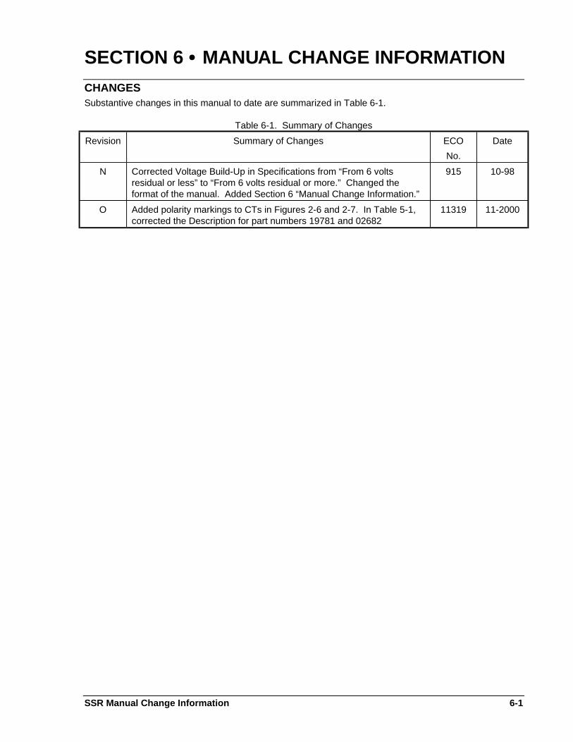
SECTION 6 •••• MANUAL CHANGE INFORMATIONCHANGESSubstantive changes in this manual to date are summarized in Table 6-1.
Table 6-1. Summary of Changes
Revision Summary of Changes ECO
No.
Date
N Corrected Voltage Build-Up in Specifications from “From 6 voltsresidual or less” to “From 6 volts residual or more.” Changed theformat of the manual. Added Section 6 “Manual Change Information.”
915 10-98
O Added polarity markings to CTs in Figures 2-6 and 2-7. In Table 5-1,corrected the Description for part numbers 19781 and 02682
11319 11-2000

RROOUUTTEE 114433,, BBOOXX 226699HHIIGGHHLLAANNDD,, IILL 6622224499 UUSSAA
hhttttpp::////wwwwww..bbaasslleerr..ccoomm,, iinnffoo@@bbaasslleerr..ccoommPPHHOONNEE 661188--665544--22334411 FFAAXX 661188--665544--22335511