Embed Size (px)
Citation preview

DOCUMENT 2811
REVISION E
November 27, 2012
Instruction Manual
Runway Threshold and End Light FAA Type L-850D
Cooper Industries
Crouse-Hinds Division
Airport Lighting Products
1200 Kennedy Road
Windsor, CT 06095
CCooppyyrriigghhtt ©© 22001122 CCooooppeerr TTeecchhnnoollooggiieess CCoommppaannyy
For Parts or Technical Service Call (860) 683-4300

DOCUMENT 2811
REV. E
Instruction Manual
Runway Threshold and End Light
FAA Type L-850D
ii
1.0 Revisions
Revision Issue/Reissue
Letter Number Description Checked Approved
A A209-005 INITIAL RELEASE KWF 1/13/09
B A209-020
Parts list 9, item 9 qty was 1 &
item 1 P/N was 21287-4 for GR
& RG combinations and
21287-2 for GX and XG
PG 2/17/09
C A209-085
8.4, 21480-X was 21321-X,
21479 was 21101 & 21477 was
21100; 9 (Parts List), item 9
P/N was 21116, item 12 P/N
was 21321-X, 21479 was 21101
& added P/N 21477 to kit
PG 6/4/09
D A210-016
Title page, Copyright 2010 was
2009; Deleted page footer; pg
1, deleted ”RR” from colors
not available; pg 8, corrected
item numbering & added –RR
versions & related data to
table
PG 2/15/10
E A212-469
Title page, copyright was 2010;
page 8, added –RX version; all
locations, Loctite 243 was 242
(P/N 10048-30); 6.1, -46 (latest
revision) was -46C
PG 11/27/12

DOCUMENT 2811
REV. E
Instruction Manual
Runway Threshold and End Light
FAA Type L-850D
iii
2.0 Limited Product Warranty
THE FOLLOWING WARRANTY IS EXCLUSIVE AND IN LIEU OF ALL OTHER
WARRANTIES, WHETHER EXPRESS, IMPLIED OR STATUTORY, INCLUDING,
BUT NOT BY WAY OF LIMITATION, ANY WARRANTY OF
MERCHANTABILITY OR FITNESS FOR ANY PARTICULAR PURPOSE.
Crouse-Hinds Airport Lighting Products (the “Company”) warrants to each original
Buyer of Products manufactured by the Company that such Products are, at the time of
delivery to the Buyer, free of material and workmanship defects, provided that no
warranty is made with respect to:
(a) any Product which has been repaired or altered in such a way, in the Company’s
judgment, as to affect the Product adversely;
(b) any Product which has, in the Company’s judgment, been subject to negligence,
accident or improper storage;
(c) any Product which has not been operated and maintained in accordance with normal
practice and in conformity with recommendations and published specification of the
Company; and;
(d) any Products, component parts or accessories manufactured by others, but supplied
by the Company (any claims should be submitted directly to the manufacturer
thereof).
Crouse-Hinds Airport Lighting Products’ obligation under this warranty is limited to use
of reasonable efforts to repair or, at its’ option, replace, during normal business hours, at
any authorized service facility of the Company, any Products, which in its judgment,
proved not to be as warranted within the applicable warranty period. All costs of
transportation of Products, claimed not to be as warranted and of repaired or replacement
Products to or from such service facility, shall be borne by Purchaser. The Company
may require the return of any Product claimed not to be as warranted to one of its
facilities as designed by the Company, transportation prepaid by Purchaser, to establish a
claim under this warranty. The cost of labor for installing a repaired or replacement
product shall be borne by Purchaser. Replacement parts provided under the terms of this
warranty are warranted for the remainder of the warranty period of the Products upon
which they are installed to the same extent as if such parts were original components
thereof. Warranty services provided under the Agreement does not assure uninterrupted
operations of Products; The Company does not assume any liability for damages caused
by any delays involving warranty service. The warranty period for the Products is 24
months from date of shipment or 12 months from date of first use whichever occurs first.

DOCUMENT 2811
REV. E
Instruction Manual
Runway Threshold and End Light
FAA Type L-850D
iv
3.0 Safety Notices
This equipment is normally used or connected to circuits that may employ voltages that
are dangerous and may be fatal if accidentally contacted by operating or maintenance
personnel. Extreme caution should be exercised when working with this equipment.
While practical safety precautions have been incorporated in this equipment, the
following rules must be strictly observed:
3.1 Keep Away from Live Circuits
Operating and maintenance personnel must at all times observe all safety regulations.
DO NOT PERFORM MAINTENANCE ON INTERNAL COMPONENTS OR RE-
LAMP WITH POWER ON.
3.2 Resuscitation
Maintenance personnel should familiarize themselves with the technique for resuscitation
found in widely published manuals of first aid instructions.
IMPORTANT
IMPORTANT: See FAA Advisory Circular AC 150/5340-26 for additional information.

DOCUMENT 2811
REV. E
Instruction Manual
Runway Threshold and End Light
FAA Type L-850D
v
4.0 Table Of Contents
Title Page i
1 Revisions ii
2 Limited Product Warranty iii
3 Safety Notices iv
4 Table of Contents v
5 Part Number Explanation 1
6 General Description 2
6.1 Runway Threshold and End Light 2
7 Installation 3
8 Maintenance 3
8.1 Cleaning Lenses 3
8.2 Relamping 4 8.3 O-Ring Replacement 4
8.4 Lens Replacement 5
8.5 Power Lead Feed-thru Replacement 5
8.6 Pressure Test 6
8.7 Cleanliness and Workmanship 6
8.8 Maintenance Program 7
9 Parts List 8
Figure 1 Exploded View of Fixture 9
Figure 2 Isometric View of Fixture 10
Figure 3 Top View of Fixture 11
Figure 4 Side View of Fixture 11
Figure 5 Bottom View of Fixture 12
Figure 6 Feed-thru detail 13

DOCUMENT 2811
REV. E
Instruction Manual
Runway Threshold and End Light
FAA Type L-850D
1
5 Part Number Explanation
850D6 – XX - PX
FAA STYLE:
C-H MODEL:
TOE LEFT COLOR (“A” SIDE):
G = GREEN (TOED BEAM)
R = RED (STRAIGHT)
X = BLANK
TOE RIGHT COLOR (“B” SIDE): G = GREEN (TOED BEAM)
R = RED (STRAIGHT)
X = BLANK
L-823 CONNECTION:
P1 = ONE PLUG
P2 = TWO PLUGS (TWO COLOR UNITS ONLY. BLANK IS NOT CONSIDERED A COLOR)
THESE COLOR COMBINATIONS ARE NOT AVAILABLE: XX, GG, XR
DOCUMENT 2811
REV. E
Instruction Manual
Runway Threshold and End Light
FAA Type L-850D
2
6 General Description
6.1 Runway Threshold and End Light
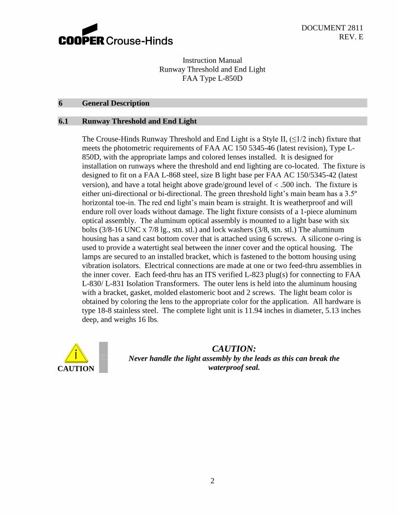
The Crouse-Hinds Runway Threshold and End Light is a Style II, (≤1/2 inch) fixture that
meets the photometric requirements of FAA AC 150 5345-46 (latest revision), Type L-
850D, with the appropriate lamps and colored lenses installed. It is designed for
installation on runways where the threshold and end lighting are co-located. The fixture is
designed to fit on a FAA L-868 steel, size B light base per FAA AC 150/5345-42 (latest
version), and have a total height above grade/ground level of .500 inch. The fixture is
either uni-directional or bi-directional. The green threshold light’s main beam has a 3.5º
horizontal toe-in. The red end light’s main beam is straight. It is weatherproof and will
endure roll over loads without damage. The light fixture consists of a 1-piece aluminum
optical assembly. The aluminum optical assembly is mounted to a light base with six
bolts (3/8-16 UNC x 7/8 lg., stn. stl.) and lock washers (3/8, stn. stl.) The aluminum
housing has a sand cast bottom cover that is attached using 6 screws. A silicone o-ring is
used to provide a watertight seal between the inner cover and the optical housing. The
lamps are secured to an installed bracket, which is fastened to the bottom housing using
vibration isolators. Electrical connections are made at one or two feed-thru assemblies in
the inner cover. Each feed-thru has an ITS verified L-823 plug(s) for connecting to FAA
L-830/ L-831 Isolation Transformers. The outer lens is held into the aluminum housing
with a bracket, gasket, molded elastomeric boot and 2 screws. The light beam color is
obtained by coloring the lens to the appropriate color for the application. All hardware is
type 18-8 stainless steel. The complete light unit is 11.94 inches in diameter, 5.13 inches
deep, and weighs 16 lbs.
CAUTION
CAUTION: Never handle the light assembly by the leads as this can break the
waterproof seal.

DOCUMENT 2811
REV. E
Instruction Manual
Runway Threshold and End Light
FAA Type L-850D
3
7 Installation
The style 2 runway threshold / end lights are shipped complete and are ready for
installation as received. Installation of a light unit is to be done with primary POWER
OFF and SECURED. At each light location, install a steel, Size B, 20 inch deep
minimum, L-868 Light Base per FAA AC 150/5340-4 (latest revision). Place the properly
sized isolation transformer(s) in the light base and make necessary primary power
connection using L-823 connectors. The light unit requires a 6.6A secondary
transformer(s). Verify that the mounting flange on the light base is clean and the o-ring
(optional on deep cans) is coated with Dow Corning FS 1292 grease and is in place on the
light base. Connect the plug from the light unit to the secondary of the previously
installed isolation transformer. Installation tool, Crouse-Hinds P/N 19999, will ease in the
installation and removal of the light unit. The threaded eyebolts on the lifting tool screw
into threaded holes in the light fixture. Lower the light unit straight down onto the base.
The light fixture is subject to optical misalignment or mechanical damage if not seated
properly. Secure the light fixture to the base with six 3/8-16 UNC x 7/8 lg., stn. stl. bolts
and lock-washers and tighten to 225 -0 +10 in-lbs. (18ft-lbs.). It is recommended that
Loctite 243 be used on the mounting bolts to prevent loosening due to vibration.
8 Maintenance
The preferred method of maintaining these lights is to periodically and systematically
replace the units and return it to the maintenance shop for renovation. As an alternative,
the units can be serviced in the field. However, it is recommended that field servicing be
limited to cleaning the lens only as described in section 8.1.
8.1 Cleaning Lenses
With a compressed air blast or suitable brushes, remove all accumulated debris from the
light channel. Clean the outer lens surface with a detergent solution. If the lens is coated
with a substance impervious to the detergent, a suitable solvent should be sparingly
applied with a wad of cotton or a patch of cloth on the end of a wood splint. After the
solvent has acted the remaining solvent and softened coating should be removed with a
clean piece of cotton or cloth. Care should be taken to avoid excessive contact between
the solvent and the lens seal. Remove all remaining solvent from lens and seal. A gentle
air blast may be used.
NOTICE
NOTICE: Warranty is void if other than Crouse-Hinds ALP parts are used to
relamp or rebuild the fixture.

DOCUMENT 2811
REV. E
Instruction Manual
Runway Threshold and End Light
FAA Type L-850D
4
8.2 Relamping
Remove and secure power to the fixture. Turn the fixture upside down and remove the six
screws holding the inner cover to the light housing. Disconnect the lamp leads. Inspect the
feed-thru terminal for signs of corrosion. Replace feed-thru assemblies per paragraph 8.5.
Install the new lamps by reversing the procedure above. Inspect/replace the optical
housing’s o-ring per paragraph 8.3. Assemble the inner cover onto the light housing.
Tighten the mounting screws to 30 in-lbs. Perform a pressure test as described in
paragraph 8.6. Clean the mounting flange area of the base. Place the fixture into the base.
Apply Loctite 243 per manufacturer’s instructions, to all mounting bolts and immediately
torque them to 225 -0+10 in-lbs.
8.3 O-Ring Replacement
Every time the unit is opened, the o-ring must be closely examined and replaced, if
necessary. Any o-ring that is stretched, torn, has permanent set, or some other defect, which
would prevent it from forming a watertight seal, must be replaced with a new o-ring.
Remove the old o-ring from the groove in the optical housing. Carefully clean the o-ring
groove and flange mating surface on the inner cover. Take care not to damage the mating
surface. Clean the new o-ring (P/N 21385) with denatured alcohol. Position the new o-ring
in the center of the groove and press it into place. Torque the inner cover screws to 30 in-
lbs. Perform a pressure test as described in paragraph 8.6. Clean the mounting flange area
of the base. Place the fixture into the base. Apply Loctite 243 per manufacturer’s
instructions, to all mounting bolts and immediately torque them to 225 -0+10 in-lbs.
NOTICE
NOTICE: The lamp is hot when fixture is energized and remains hot for a
short time after fixture is turned off.
NOTICE
NOTICE: A bad o-ring seal is the most common cause of inset fixture leaks.
A new o-ring must be installed every time the
Optical Assembly is opened
NOTICE
NOTICE: The groove is designed to be wider than the o-ring. This provides room for the
displacement of the o-ring when compressed between the housing and mating surface.
Properly tightened screws are important in obtaining a complete seal.

DOCUMENT 2811
REV. E
Instruction Manual
Runway Threshold and End Light
FAA Type L-850D
5
8.4 Lens Replacement
If an outer lens is broken, leaks, or is badly pitted or scarred, it must be replaced. It is
highly recommended that this task be performed in a clean shop environment. Lens
Replacement Kit P/N 21480-X contains all necessary parts to change a lens. Remove and
secure power to the fixture. Turn the fixture upside down and remove the six screws
holding the inner cover to the light housing. Remove the lens retaining bracket screws from
the light housing. Remove the lens-retaining bracket and discard the lens-retaining gasket.
Firmly push the lens/boot assembly from the outside of the light housing; discard the old lens
and boot. Thoroughly clean the lens opening with isopropyl alcohol and let dry. Inspect the
lens opening for scratches or pits; a damaged lens-opening surface will not seal properly.
Place a new lens boot (P/N 21277) over the replacement lens (P/N 21276-X). Apply a thin
coat of Dow Corning FS 1292 grease over the entire outside surface of the lens boot.
Align the lens/boot assembly in the lens opening and press it into place. Verify that the
lens boot is not pinched in the lens opening. Using a new lens-retaining gasket (P/N
21479), fasten the lens-retaining bracket (P/N 21477) to the light housing. Torque the
mounting screws to 30 in-lbs. Inspect/replace the optical housing’s o-ring per paragraph
8.3. Assemble the inner cover onto the light housing. The screw-hole patterns in the inner
cover and light housing are offset to insure proper alignment. Torque the mounting screws
to 30 in-lbs. Perform a pressure test per paragraph 8.6. Clean the mounting flange area of
the base. Place the fixture into the base. Apply Loctite 243 per manufacturer’s
instructions, to all mounting bolts and immediately torque them to 225 -0+10 in-lbs.
8.5 Power Lead/ Feedthru Replacement
The power leads are connected to water tight feedthrus in the inner cover. There is a
coating of RTV over the connections, and an epoxy material to encapsulate the entire
assembly. The power cord and feedthru components can be replaced, but shipping
restrictions prohibit Crouse-Hinds from supplying the epoxy encapsulating material. The
complete inner cover assembly, with leads is part number 21286-1 for one plug, and
21286-2 for two plugs. Follow the instructions below to rebuild the power lead/feedthru
assembly.
Remove and secure power to the fixture. Turn the fixture upside down and remove the
six screws holding the inner cover to the light housing. Remove the Teflon leads inside the
cover. Cut the power leads off at the encapsulating material. Using a hammer and chisel,
separate the encapsulating material from the inner cover. Be careful to not damage the inner
cover. Remove and discard the feedthru assemblies. Carefully clean the feed-thru mounting
area in the inner cover, inspect for any mechanical damage that would prevent a water tight
seal. Replace the feedthru components, refer to Figure 6 for part numbers and orientation.
Replace the Teflon leads inside the cover. Replace the optical housing’s o-ring per paragraph

DOCUMENT 2811
REV. E
Instruction Manual
Runway Threshold and End Light
FAA Type L-850D
6
8.3. Assemble the inner cover onto the light housing. The screw-hole patterns in the inner
cover and light housing are offset to insure proper alignment. Torque the mounting screws to
30 in-lbs. Perform a pressure test per paragraph 8.6. Clean the mounting flange area of the
support ring. Place the optical assembly into the base. Apply Loctite 243 per manufacturer's
instructions, to all mounting bolts and immediately torque them to 225 -0+10 in-lbs.
8.6 Pressure Test
A light fixture should be subjected to a 20-psi air pressure test to verify that it is
waterproof whenever it has been opened or components have been replaced. A tire valve
style pressure fitting is located on the bottom of the inner cover. Pressurize the fixture to
20-psi then place it in a tub of water or use a soap solution to locate escaping air bubbles.
Carefully inspect the areas around the lens, inner cover seal, and feed-thru adapter for
leaks. Relieve the internal air pressure before installing the fixture or attempting to repair a
leak.
8.7 Cleanliness and Workmanship
Service life depends upon the entire assembly being waterproof. All surfaces must be
clean, dry and free of all foreign matter if the light fixture is to operate for extended
periods without requiring maintenance.
WARNING
WARNING: Do not exceed 20-psi when pressure testing the fixture. Serious injury and/or permanent
damage to the fixture may result if a higher air pressure is used. Once the pressure test is
complete, be sure to relieve the air pressure.

DOCUMENT 2811
REV. E
Instruction Manual
Runway Threshold and End Light
FAA Type L-850D
7
8.8 Maintenance Program
In order to insure maximum light fixture life, the installed units should be subject to a
maintenance program in accordance with the following: A daily operation check should be
made of the lighting fixture. The lights should be energized and visually inspected. If any
fixtures are out, the location of the fixture should be recorded and the lamps replaced at a
time when the circuit is de-energized. (See Section 8.2)
8.8.1 Regular cleaning is necessary in order to insure that inset lighting fixtures operate at
maximum efficiency. The lens should be cleaned periodically with a soft cloth and
solvent. The weather and the location of the fixtures will dictate the regularity and type of
cleaning.
8.8.2 Snowplow operators should exercise extra care not to strike the light fixtures with
snowplow blades (use rubber blades for added protection to the fixture.) After snowplow
removal operations, inspect all light fixtures to locate and replace if necessary, any
damaged Light Assemblies. Passes over the light rows should be made with a power
broom only if practical. Whenever snowplows must traverse in-pavement light fixtures,
they should be traveling at less than 5 mph or have the blades lifted clear of the fixture.
Recommended snow removal techniques are described in AC 150/5200-23.
8.8.3 The light is designed to exclude both ground and surface water from entering. If the lights
are not properly maintained (i.e., bolts tightened and seals in good condition) water may
enter the fixture. To prevent this from occurring, it is recommended that each fixture be
inspected for the presence of water at least once a month. More frequent inspection is
desirable during and following rainy seasons.
8.8.4 Inset light hold-down bolts should be checked for proper torque (225 +5, -0, in-lbs.) at
least once every three months or whenever a fixture is serviced regardless of the season.
Light fixtures in and around the Touchdown Zone area are especially prone to vibration
damage if the mounting bolts are not properly torqued. The mounting surface of the light
base must be clean and free of foreign matter when checking mounting bolts.
8.8.5 If any fixture contains water, the water should be removed and the entire fixture cleaned
and dried. Perform a pressure test per paragraph 8.6 to locate the source of the leak.
Replace the o-ring (21385), see Section 8.3.

DOCUMENT 2811
REV. E
Instruction Manual
Runway Threshold and End Light
FAA Type L-850D
8
9 Parts Lists
ITEM NO. QTY PART NUMBER DESCRIPTION
1 1 SEE TABLE HOUSING, OPTICAL, ASS'Y,
2 1 21385 O-RING, SIZE #2-273, 70 DUROMETER, SILICONE, POST CURED
3 1 SEE TABLE COVER, BOTTOM, ASS'Y,
4 1 SEE TABLE LAMP BASE ASSEMBLY
5 8 20356 GROMMET
6 4 19143-2 SPACER
7 4 10B08-019D16 PAN HD, #10-32 x .5 LG, SSTL
8 6 10000-470 SCREW, 100° FLAT HD/DRI-LOC, #10-32 x 7/16 LG, 18-8 SS
9 SEE TABLE 21474 48 WATT LAMP, THRESHOLD
10 SEE TABLE 21128 105 WATT LAMP, END
11 A/R 10047-417 MALE TERMINAL FOR LEAD ASSEMBLY
12 1 2811 INSTRUCTION MANUAL
13 A/R 21480-X LENS REPLACEMENT KIT (G = green. R = red) (Includes 21276-X lens, 21277 lens boot, 21479 lens retaining gasket,
and gasket lubricant), 21477 lens retaining bracket
PART NUMBER ITEM 1 P/N ITEM 3 P/N ITEM 4 P/N ITEM 9
QTY ITEM 10
QTY
850D6-GR-P1 21287-14 21286-1 21465-GR 1 1
850D6-RG-P1 21287-13 21286-1 21465-RG 1 1
850D6-GR-P2 21287-14 21286-2 21465-GR 1 1
850D6-RG-P2 21287-13 21286-2 21465-RG 1 1
850D6-GX-P1 21287-16 21286-1 21465-GX 1 0
850D6-XG-P1 21287-15 21286-1 21465-XG 1 0
850D6-RR-P1 21287-17 21286-1 21465-RR 0 2
850D6-RR-P2 21287-17 21286-2 21465-RR 0 2
850D6-RX-P1 21287-18 21286-1 21465-RX 0 1

DOCUMENT 2811
REV. E
Instruction Manual
Runway Threshold and End Light
FAA Type L-850D
9
Figure 1: Exploded View of Fixture

DOCUMENT 2811
REV. E
Instruction Manual
Runway Threshold and End Light
FAA Type L-850D
10
Figure 2: Isometric View of Fixture

DOCUMENT 2811
REV. E
Instruction Manual
Runway Threshold and End Light
FAA Type L-850D
11
Figure 3: Top View of Fixture
Figure 4: Side View of Fixture

DOCUMENT 2811
REV. E
Instruction Manual
Runway Threshold and End Light
FAA Type L-850D
12
Figure 5: Bottom View of Fixture

DOCUMENT 2811
REV. E
Instruction Manual
Runway Threshold and End Light
FAA Type L-850D
13
NOT SHOWN A/R A/R 10048-63 RTV 116
NOT SHOWN 1 2 21038 LEAD ASSEMBLY, L-823
8 2 4 10035-33-010 O-RING
7 2 4 10030-100 WASHER, SHOULDER,INSULATING
6 2 4 10030-108 WASHER, FLAT, INSULATING
5 4 8 10030-57 WASHER, FLAT, SS, #1/4
4 2 4 20017 LEAD LUG
3 2 4 10K04-025D NUT, HEX, SS, #1/4-20
2 2 4 11A12-016D LOCKWASHER, SPLIT, #8, SS
1 2 4 10A06-016D10 SCREW, PAN HD, #8-32X5/16, SS
ITEM NO. 21286-1 QTY 21286-2 QTY PART NUMBER DESCRIPTION
Figure 6: Feedthru detail
FEEDTHRU REPLACEMENT INSTRUCTIONS
1. Torque item 3 to 30 in-lbs
2. Coat items 3, 4, 5 and lead terminals, on the outside of the
cover only, with item 10. Allow to cure for 8 hours.
3. Encapsulate feedthru assembly with Emerson & Cummings
catalyst 9 / resin 2651 or Mavidon catalyst 4195B / resin
4195A. Allow to cure per manufacturer’s instructions. The
wire leads exit the bottom of the inner cover, not the sides. A
temporary dam must be placed across the inner cover side to
hold the epoxy in place as it cures.