Embed Size (px)
Citation preview

INTERCOM STATIONS
I N S T R U C T I O N M A N U A L
ICS-102/62

ICS-102/62 Intercom Stations Instruction Manual ©1998, 2000, 2004, 2005 Vitec Group Communications, Inc.All Rights Reserved
Part Number 810302 Rev. A
Vitec Group Communications, Inc.4065 Hollis StreetEmeryville, CA 94608-3505U.S.A
Clear-Com is a registered trademark of Vitec Group Communications, Inc.The Clear-Com Logo is a registered trademark of Vitec Group Communications, Inc. Eclipse is a registered trademark of Vitec Group Communications, Inc. Windows is a registered trademark of Microsoft Corp.

CONTENTSIMPORTANT SAFETY INSTRUCTIONS v
OPERATION 1-1Introduction . . . . . . . . . . . . . . . . . . . . . . . . . . . . . . . . . . . . . . . . . . . . . . . . . 1-1
Description . . . . . . . . . . . . . . . . . . . . . . . . . . . . . . . . . . . . . . . . . . . . . . . . . . 1-1
Front-Panel Controls and Indicators . . . . . . . . . . . . . . . . . . . . . . . . . . . . . . . 1-1
Communication-Error Indicator . . . . . . . . . . . . . . . . . . . . . . . . . . . . . . . . 1-2
Speaker/Headset Level Controls. . . . . . . . . . . . . . . . . . . . . . . . . . . . . . . . . 1-2
Intercom Volume Control . . . . . . . . . . . . . . . . . . . . . . . . . . . . . . . . . . . . . 1-2
Page Override . . . . . . . . . . . . . . . . . . . . . . . . . . . . . . . . . . . . . . . . . . . . . . 1-2
Mute Level . . . . . . . . . . . . . . . . . . . . . . . . . . . . . . . . . . . . . . . . . . . . . . . . 1-2
Listen Level Adjustment . . . . . . . . . . . . . . . . . . . . . . . . . . . . . . . . . . . . . . 1-2
Talk/Listen Selectors and Indicators. . . . . . . . . . . . . . . . . . . . . . . . . . . . . . . . 1-3
Selector Operation. . . . . . . . . . . . . . . . . . . . . . . . . . . . . . . . . . . . . . . . . . . 1-3
Talk and Listen Indicators . . . . . . . . . . . . . . . . . . . . . . . . . . . . . . . . . . . . . 1-3
Monitoring/Eavesdropping Indicators . . . . . . . . . . . . . . . . . . . . . . . . . . . . 1-3
Call-Waiting Indicator. . . . . . . . . . . . . . . . . . . . . . . . . . . . . . . . . . . . . . . . 1-3
In-Use Tally Indicator . . . . . . . . . . . . . . . . . . . . . . . . . . . . . . . . . . . . . . . . 1-3
Telephone Off-Hook Tally Indicator . . . . . . . . . . . . . . . . . . . . . . . . . . . . . 1-4
Radio Receiver Active Tally Indicator . . . . . . . . . . . . . . . . . . . . . . . . . . . . 1-4
Station Connected Tally Indicator . . . . . . . . . . . . . . . . . . . . . . . . . . . . . . . 1-4
Audio Presence Tally Indicator. . . . . . . . . . . . . . . . . . . . . . . . . . . . . . . . . . 1-4
Answer-Back Facility . . . . . . . . . . . . . . . . . . . . . . . . . . . . . . . . . . . . . . . . . . . 1-4
Answer Back Selector. . . . . . . . . . . . . . . . . . . . . . . . . . . . . . . . . . . . . . . . . 1-4
Answer-Back Label Selection . . . . . . . . . . . . . . . . . . . . . . . . . . . . . . . . . . . 1-5
Removing Labels from the Answer-Back Stack. . . . . . . . . . . . . . . . . . . . . . 1-5
Function Selectors . . . . . . . . . . . . . . . . . . . . . . . . . . . . . . . . . . . . . . . . . . . . . 1-5
Panel Mic Selector . . . . . . . . . . . . . . . . . . . . . . . . . . . . . . . . . . . . . . . . . . . 1-5
Speaker On Selector. . . . . . . . . . . . . . . . . . . . . . . . . . . . . . . . . . . . . . . . . . 1-5
Mic On Selector . . . . . . . . . . . . . . . . . . . . . . . . . . . . . . . . . . . . . . . . . . . . 1-5
Listen Level Selector . . . . . . . . . . . . . . . . . . . . . . . . . . . . . . . . . . . . . . . . . 1-6
Listen-Level Mode . . . . . . . . . . . . . . . . . . . . . . . . . . . . . . . . . . . . . . . . . 1-6
Listen Level Reset . . . . . . . . . . . . . . . . . . . . . . . . . . . . . . . . . . . . . . . . . 1-6
Call Signals . . . . . . . . . . . . . . . . . . . . . . . . . . . . . . . . . . . . . . . . . . . . . . 1-6
Remote Telephone Line Release . . . . . . . . . . . . . . . . . . . . . . . . . . . . . . 1-7
Rear-Panel Connectors . . . . . . . . . . . . . . . . . . . . . . . . . . . . . . . . . . . . . . . . . 1-7
I C S - 1 0 2 / 6 2 I N T E R C O M S T A T I O N i
Miscellaneous Connector. . . . . . . . . . . . . . . . . . . . . . . . . . . . . . . . . . . . . . 1-7
Logic Inputs #1 and #2 . . . . . . . . . . . . . . . . . . . . . . . . . . . . . . . . . . . . . 1-7
Programmable Relay . . . . . . . . . . . . . . . . . . . . . . . . . . . . . . . . . . . . . . . 1-8
Mute Relay . . . . . . . . . . . . . . . . . . . . . . . . . . . . . . . . . . . . . . . . . . . . . . 1-8
OPT-100 Auxiliary Audio Option . . . . . . . . . . . . . . . . . . . . . . . . . . . . . . . 1-9
Hot Mic Output . . . . . . . . . . . . . . . . . . . . . . . . . . . . . . . . . . . . . . . . . . 1-9
Studio/Stage Announce Audio and Relay Outputs . . . . . . . . . . . . . . . . 1-9
Auxiliary Audio Line Level Output. . . . . . . . . . . . . . . . . . . . . . . . . . . . 1-9
Expansion Panel Operation . . . . . . . . . . . . . . . . . . . . . . . . . . . . . . . . . . . . . . 1-9
INSTALLATION 2-1Introduction . . . . . . . . . . . . . . . . . . . . . . . . . . . . . . . . . . . . . . . . . . . . . . . . . 2-1
Mounting Stations. . . . . . . . . . . . . . . . . . . . . . . . . . . . . . . . . . . . . . . . . . . . . 2-1
Wiring. . . . . . . . . . . . . . . . . . . . . . . . . . . . . . . . . . . . . . . . . . . . . . . . . . . . . . 2-1
Analog Matrix Frame to Station Wiring. . . . . . . . . . . . . . . . . . . . . . . . . . . 2-2
Digital Matrix Frame to Station Wiring. . . . . . . . . . . . . . . . . . . . . . . . . . . 2-3
Single-Pair Digital . . . . . . . . . . . . . . . . . . . . . . . . . . . . . . . . . . . . . . . . . 2-3
Coax Digital . . . . . . . . . . . . . . . . . . . . . . . . . . . . . . . . . . . . . . . . . . . . . 2-3
Matrix Station Miscellaneous Connector Wiring . . . . . . . . . . . . . . . . . . . . 2-4
External Program Feed Input. . . . . . . . . . . . . . . . . . . . . . . . . . . . . . . . . 2-4
Logic Input #1 and #2. . . . . . . . . . . . . . . . . . . . . . . . . . . . . . . . . . . . . . 2-5
Mute Relay Contacts . . . . . . . . . . . . . . . . . . . . . . . . . . . . . . . . . . . . . . . 2-6
Programmable Relay Contacts . . . . . . . . . . . . . . . . . . . . . . . . . . . . . . . . 2-6
OPT-100 Auxiliary Audio I/O Option . . . . . . . . . . . . . . . . . . . . . . . . . . . 2-7
Hot Mic Output . . . . . . . . . . . . . . . . . . . . . . . . . . . . . . . . . . . . . . . . . . 2-7
Studio/Stage Announce Audio and Relay Outputs . . . . . . . . . . . . . . . . 2-7
Auxiliary Audio Line Level Output . . . . . . . . . . . . . . . . . . . . . . . . . . . . 2-8
Mains AC Power . . . . . . . . . . . . . . . . . . . . . . . . . . . . . . . . . . . . . . . . . . . . . . 2-8
Adjustments . . . . . . . . . . . . . . . . . . . . . . . . . . . . . . . . . . . . . . . . . . . . . . . . . 2-9
Headset Sidetone . . . . . . . . . . . . . . . . . . . . . . . . . . . . . . . . . . . . . . . . . . . . 2-9
Panel Microphone Gain. . . . . . . . . . . . . . . . . . . . . . . . . . . . . . . . . . . . . . . 2-9
Speaker Mute. . . . . . . . . . . . . . . . . . . . . . . . . . . . . . . . . . . . . . . . . . . . . . 2-10
Page Volume Level. . . . . . . . . . . . . . . . . . . . . . . . . . . . . . . . . . . . . . . . . . 2-10
Station-to-Matrix Card Baud Rate. . . . . . . . . . . . . . . . . . . . . . . . . . . . . . 2-10
MAINTENANCE 3-1Introduction . . . . . . . . . . . . . . . . . . . . . . . . . . . . . . . . . . . . . . . . . . . . . . . . . 3-1
Station Reset . . . . . . . . . . . . . . . . . . . . . . . . . . . . . . . . . . . . . . . . . . . . . . . . . 3-1
Troubleshooting . . . . . . . . . . . . . . . . . . . . . . . . . . . . . . . . . . . . . . . . . . . . . . 3-1
Technical Reference (Bills of Materials, Component Drawings, Schematics) . 3-3
I C S - 1 0 2 / 6 2 I N T E R C O M S T A T I O Ni i

SPECIFICATIONS 4-1ICS-102/62 . . . . . . . . . . . . . . . . . . . . . . . . . . . . . . . . . . . . . . . . . . . . . . . . . . 4-1
OPT-100 Auxiliary Audio I/O Option . . . . . . . . . . . . . . . . . . . . . . . . . . . . . 4-3
Accessory Panels . . . . . . . . . . . . . . . . . . . . . . . . . . . . . . . . . . . . . . . . . . . . . . 4-3
VITEC GROUP COMMUNICATIONS WARRANTY 5-1Technical Support . . . . . . . . . . . . . . . . . . . . . . . . . . . . . . . . . . . . . . . . . . . . . 5-1
Exceptions . . . . . . . . . . . . . . . . . . . . . . . . . . . . . . . . . . . . . . . . . . . . . . . . . . . 5-1
Warranty Repairs . . . . . . . . . . . . . . . . . . . . . . . . . . . . . . . . . . . . . . . . . . . . . . 5-2
Non-Warranty Repairs. . . . . . . . . . . . . . . . . . . . . . . . . . . . . . . . . . . . . . . . . . 5-2
I C S - 1 0 2 / 6 2 I N T E R C O M S T A T I O N i i i

I C S - 1 0 2 / 6 2 I N T E R C O M S T A T I O Ni v

IMPORTANT SAFETY INSTRUCTIONS
For your safety, it is important to read and follow these instructions before operating an ICS-102/62 intercom station:
(1) WARNING: To reduce the risk of fire or electric shock, do not expose an ICS-102/62 intercom station to rain or moisture. Do not operate an ICS-102/62 intercom station near water, or place objects containing liquid on it. Do not expose an ICS-102/62 intercom station to splashing or dripping water.
(2) For proper ventilation, make sure ventilation openings are not blocked. Install the ICS-102/62 according to the directions in the Installation Chapter of this manual.
(3) Do not install an ICS-102/62 intercom station near a heat source such as a radiator, heat register, stove, or other apparatus (including amplifiers) that produces heat. Do not place naked flame sources such as candles on or near an i-station.
(4) Do not defeat the safety purpose of the polarized or grounding-type plug. A polarized plug has two blades, with one blade wider than the other. A grounding-type plug has two blades and a third grounding prong. The wide blade or the third prong is provided for your safety. If the provided plug does not fit into your outlet, consult an electrician for replacement of the obsolete outlet.
(5) Protect the power plug from being walked on or pinched particularly at plugs, convenience receptacles, and the point where they exit from the i-station’s chassis.
(6) Only use attachments/accessories specified by Clear-Com Communication Systems.
(7) Unplug the ICS-102/62 station during lightning storms or when unused for long periods of time.
(8) Refer all servicing to qualified service personnel. Servicing is required when:
•The ICS-102/62 station has been damaged in any way, such as when a power-supply cord or plug is damaged.
•Liquid has been spilled or objects have fallen into the ICS-102/62 station’s chassis.
•The ICS-102/62 station has been exposed to rain or moisture.
•The ICS-102/62 station does not operate normally.
•The ICS-102/62 station has been dropped.
Please familiarize yourself with the safety symbols in Figure 1. When you see these symbols on an ICS-102/62 intercom station, they warn you of the potential danger of electric shock if the station is used improperly. They also refer you to important operating and maintenance instructions in the manual.
Please read and follow these
instructions before operating
an ICS-102/62 intercom
station.
I C S - 1 0 2 / 6 2 I N T E R C O M S T A T I O N v

Figure 1: Safety Symbols
CAUTIONRISK OF ELECTRIC SHOCK
DO NOT OPEN
This symbol alerts you to the presence of uninsulated dangerousvoltage within the product's enclosure that might be of sufficient magnitude to constitute a risk of electric shock. Do not open the product's case.
This symbol informs you that important operating and main-tenance instructions are included in the literature accompanyingthis product.
I C S - 1 0 2 / 6 2 I N T E R C O M S T A T I O Nv i

OPERATION
INTRODUCTIONThis booklet describes how to use the ICS-102 and ICS-62 intercom stations and their digital equivalents, the ICS-102T and ICS-62T intercom stations. Station operators can use this manual after the Eclipse System has been correctly installed and configured.
DESCRIPTIONThe ICS-102/102T and ICS-62/62T intercom stations are each assembled in a small, 1-RU high (1.75 in. or 44.45 mm) chassis. The ICS-102/102T has ten selectors while the ICS-62/62T has six. Each station has the following features:
• Individually adjustable listen levels
• Fits in one rack unit (1.75 inches or 44.45 mm) of a standard equipment rack
• Built-in speaker and optional plug-in panel microphone
• Front-panel headset connector
• Call signalling capability
• Answer Back facility
• Local program input without front-panel control
• Programmable relay
• Mute relay
• Two logic inputs for external control of selected station functions
The station can both be equipped with the following options:
• XPL-12 and XPL-22 Expansion Panels
• OPT-100 Auxiliary Audio Output.
FRONT-PANEL CONTROLS AND INDICATORSThe front-panel controls and indicators include:
• Communication-error indicator
• Talk/listen selectors and indicators
• Answer Back facility
• Function buttons
This chapter describes how
to operate the ICS-102 and
ICS-62 intercom stations
and the ICS-102T and
ICS-62T digital stations.
1
I
C S - 1 0 2 / 6 2 I N T E R C O M S T A T I O N 1 - 1
COMMUNICATION-ERROR INDICATORIf the station should lose data communication with the matrix frame, all of the red lights on the front of the station will flash slowly.
When data communication is restored, the station will automatically return to normal operation.
SPEAKER/HEADSET LEVEL CONTROLSTo adjust the speaker or headset volume, use the knob labeled “intercom,” as described below. The speaker volume can also be affected by three software-controlled functions: Page Override, Mute Level, and Listen Level Adjustment.
INTERCOM VOLUME CONTROLThe “intercom” volume control sets the overall level of all signals coming from the matrix frame, except for the page mode, which is controlled by an internal software function (see the next section “Page Override.”)
PAGE OVERRIDEPage override is a special function in the station in which the intercom volume defaults to a preset to a value when commanded to by the central matrix. Any fixed group can be assigned the page-override function through the configuration program.
The configuration program determines preset value for each station. If the preset value is lower than the setting of the front-panel volume control, the volume will be controlled by the front-panel control.
MUTE LEVELThis turns down the speaker level when any talk is active at the station. The amount of muting (measured in dB) is set by the configuration program for each station. This function helps prevent possible feedback. The maximum amount of muting is 15 dB below full volume. If the front panel control is set below that level, then muting will have no effect.
LISTEN LEVEL ADJUSTMENTThe level of any active listen path can be adjusted individually. Refer to “Listen-Level Mode” later in this chapter.
I C S - 1 0 2 / 6 2 I N T E R C O M S T A T I O N1 - 2
TALK/LISTEN SELECTORS AND INDICATORSThe following section describes the operation of the talk/listen selectors and their associated indicators.
SELECTOR OPERATIONThe selectors operate as both talk and listen selectors; they also work as volume controls when the station is in listen-level mode (see “Listen Level Mode” later in this chapter). Pressing a selector down accesses a talk label; pushing it up accesses a listen label. Pushing the talk selector down and quickly releasing it will “latch” the selector and the talk path will stay active until it is pressed again. Pressing and holding a talk selector causes the talk path to stay active only for as long as it is held down. Listen selectors operate in the same manner.
To prevent the selector on the station from latching in the talk position (local latch disable), or to prevent any station from latching a talk to the station (global latch disable) use the configuration program.
TALK AND LISTEN INDICATORSWhen a talk path is active, the red LED above the selector lights continuously. When a listen path is active, the green LED above the selector lights continuously.
MONITORING/EAVESDROPPING INDICATORSIf any other station begins monitoring a station, a beep (the monitoring-alert tone) will sound at the station.
To inhibit the monitoring-alert tone, use the configuration program.
CALL-WAITING INDICATORIf a station calls another station with a selector programmed for that label, the LED will rapidly flash red. This flashing is a call-waiting tally. To answer the incoming call, push the indicated talk selector. The call-waiting tally clears when the call is answered, or after the call is terminated and the answer-back time-out lapses.
If another station calls a station without a button programmed for that label, it will be placed in the answer-back stack (see “Removing Labels from the Answer-Back Stack.”)
IN-USE TALLY INDICATORIf a selector is assigned to a label and another station is currently using that label, the LED will double-flash once per second to indicate the label is in use. This tally must be enabled from the configuration software.
I C S - 1 0 2 / 6 2 I N T E R C O M S T A T I O N 1 - 3

TELEPHONE OFF-HOOK TALLY INDICATORWhen a telephone interface is assigned to a talk selector, the talk LED will flash once per second if that telephone is off the hook. This tally must be enabled from the configuration program.
RADIO RECEIVER ACTIVE TALLY INDICATORWhen a two-way radio interface port is assigned to a talk selector, the LED will flash once per second when that radio’s receiver is active. This tally must be enabled from the configuration program.
STATION CONNECTED TALLY INDICATORThis tally is used when a station is connected to the frame by a high-speed data line (such as an ISDN or T1 line) that might be inactive periodically. The red LED of any talk selector associated with that station will flash once per second when the station is on-line. This tally must be enabled from the configuration program.
AUDIO PRESENCE TALLY INDICATORWhen a label is assigned to a listen selector, the LED will flash once per second to indicate someone is talking on that channel. This tally must be enabled from the configuration program.
ANSWER-BACK FACILITYThe primary function of the answer-back facility is to answer calls from other stations or interfaces not assigned to a station’s selectors.
The following sections describe the use of the answer-back facility.
ANSWER BACK SELECTORYou use the Answer Back selector to answer calls from stations and interfaces that are not assigned to your station.
When a call from a station or interface not assigned to the station arrives:
• The calling station’s label will be placed in the answer-back stack.
• The red LED will flash.
These two conditions will continue until the call is answered, or until the answer-back time-out period lapses and the caller’s label is automatically removed. To answer the call, push the Answer Back selector. The red LED will turn off and the green LED will turn on, indicating an active talk path to the caller. The talk path is active for as long as the selector is held.
Note: The Answer Back selector cannot be latched; it is a momentary-only function.
Calls from stations or interfaces assigned to station selectors will only be indicated by their associated LEDs.
I C S - 1 0 2 / 6 2 I N T E R C O M S T A T I O N1 - 4

ANSWER-BACK LABEL SELECTIONIf another call comes in while using the answer-back selector:
• The user will hear the caller’s voice.
• The label will be placed in the answer-back stack.
To answer the next caller:
1. Push up on the Answer Back selector to remove the current caller’s label.2. Press down on the Answer Back selector to talk to the next caller.
REMOVING LABELS FROM THE ANSWER-BACK STACKAny label will be automatically removed from the stack if it is not answered within a certain time interval, which is set by the answer-back auto-clear time in the configuration program.
To manually remove the current caller’s label from the answer-back stack, push up on the Answer Back selector.
FUNCTION SELECTORSTwo dual-function toggle switches allow you to choose among the following four functions:
• Panel Mic
• Speaker On
• Mic On
• Listen Level
PANEL MIC SELECTORThis selector selects the panel or headset microphone. If a headset is plugged in, the station will automatically switch to headset microphone operation. If the headset is unplugged, the station will automatically switch back to panel microphone operation. The LED will be on when the panel microphone is active.
SPEAKER ON SELECTORThis selector functions only when a headset is plugged into the station. To toggle the speaker on and off, push the Speaker On selector. The LED indicates when the speaker is on.
MIC ON SELECTORThis selector activates the panel or headset microphone, whichever has been selected. The LED indicates when the microphone is on. If a talk is activated while the microphone is off, it will turn on.
I C S - 1 0 2 / 6 2 I N T E R C O M S T A T I O N 1 - 5

LISTEN LEVEL SELECTORThe Listen Level selector has four functions:
• Activating the listen-level mode
• Resetting the listen-level settings
• Sending call signals
• Releasing auto-answered telephone lines
Listen-Level Mode
To use the listen-level adjust mode, push (for less than 1 sec.) and quickly release the Listen Level selector.
The LEDs of all active listen selectors will begin to flash to indicate the function is on.
Note: Only active selectors can be adjusted in listen-level mode.
Use the selector associated with the intended label to increase (up) or decrease (down) the volume.
To exit, push the Listen Level selector or wait for the 3 sec. time-out.
Note: If the active listen path is pushed higher than the maximum value, the other paths will be driven down so that the desired path has more emphasis.
Listen Level Reset
To reset the Listen Level to default settings:
1. Press (for less than 1 sec.) and quickly release the Listen Level selector.2. Press and hold the Listen Level selector for 3 sec.3. Release the Listen Level selector.
Call Signals
To activate a call signal:
1. Push and hold (for at least 1 sec.) the Listen Level selector until the station indicates it is in Call Signal mode.
2. Push down the talk selector with the desired label.
The call signal will be sent each time the selector with that label assignment is pushed down and will remain so until the call-signal mode times out (about 5 sec.).
Call signals can be issued to any talk label assigned to a station’s talk/listen selectors. If more than one label is assigned to a selector, all labels will receive the signal. If a label is a fixed group, the entire group will receive the call signal. If the label is a party line, then every station listening on the party line will receive the call signal.
I C S - 1 0 2 / 6 2 I N T E R C O M S T A T I O N1 - 6

Remote Telephone Line Release
This function is available only if specifically enabled in the configuration program.
To hang up a telephone interface left off the hook:
1. Push and hold the Listen Level selector for at least 1 sec. to activate the call-signal mode.
2. While holding the Listen Level selector, press the talk selector of the desired telephone’s label.
3. Release the Listen Level selector.
Note: In addition to hanging up the telephone interface, this will deactivate any talk/listen selector set to the interface from anywhere in the system.
REAR-PANEL CONNECTORSThis section describes only those rear-panel functions directly affecting normal station operation. These include the functions available through the “Miscellaneous” connector and those added by the use of the “OPT-100 Auxiliary Audio” connector. The actual functions these inputs and outputs perform depend on the installation of the individual station. This section only describes the general use of these functions. For a more complete description, see the Installation chapter.
MISCELLANEOUS CONNECTORThe Miscellaneous connector includes the following functions:
• Logic input #1
• Logic input #2
• Programmable relay
• Mute relay
Logic Inputs #1 and #2
Each input can control one of several functions, determined through the configuration program. Typically, these inputs are connected to an external foot switch, a panel-mounted switch, or the logic output of another device.
The following functions are available:
• Mic On/Off—toggles the station’s microphone on and off.
• Mute Mic Output To Frame—turns off the audio from the station to the frame. It does not turn off the Hot Mic output
• Mic Off —momentarily turns off the station’s microphone.
• Answer Back Talk/Clear—functions the same as the station’s “Answer Back” selector. Holding down the switch activates a talk to a label in the answer-back stack. To clear the label, quickly press and release the switch.
I C S - 1 0 2 / 6 2 I N T E R C O M S T A T I O N 1 - 7

• Studio Announce—sends the output of the station’s selected microphone (panel or headset) to the station’s Studio Announce (SA) audio output, and activates the SA relay. The microphone output is not sent to the frame. The SA output and relay are only present if the station has the OPT-100 Auxiliary Audio I/O Option installed.
• Speaker OFF—turns off the station speaker, disabling all audible output from the station.
• PTT: Activate All Talk Keys—implements a push-to-talk function for all talk selectors. When the logic input is active, the station operates normally. When the logic input is deactivated, all active talk selectors are disabled. Any controls (relays, etc.) assigned to the labels are activated or deactivated along with their assigned labels. The LED indicators associated with the active talk selectors operate normally regardless of the PTT status. This input only controls latched talks.
• Activate Talk Switch #1— equivalent to pressing the station’s first (leftmost) talk selector; a momentary and latching activation.
• Activate Talk Switch #2—equivalent to pressing the station’s second talk selector; a momentary and latching activation.
• Activate Listen Labels Button—equivalent to pressing the “Listen Labels” button to display listen labels on any display expansion panel (XPL-12 or XPL-22) connected to the station.
• PTT: Activate Two-Way Radio Keys—implements a push-to-talk function for all two-way radio talk selectors. When the logic input is active, the station operates normally. When the logic input is deactivated, all active two-way radio talk selectors are disabled. Any controls (relays, etc.) assigned to the labels are activated or deactivated along with their assigned labels. The LED indicators associated with the active two-way radio talk selectors operate normally regardless of the PTT status. This input only controls latched talks.
Programmable Relay
Each Eclipse system station includes a relay controlled by the system program and independent of the local station function. This relay can be assigned to any label(s) in the system, which will activate whenever a talk or listen is set to that label(s). If activating the relay is the only action desired, assign the relay to a “control” label. See the Eclipse Configuration System Manual for more details.
The relay can activate an external device, such as an applause light in a studio, a cue light, or a security door lock. Any programmable relay in the system can be activated from any station in the system, including a direct-inward-access caller.
Mute Relay
The mute relay is activated whenever any talk selector is activated at the station. The mute relay is commonly wired such that whenever it is activated, the volume of the monitor speaker in that room is decreased (muted).
I C S - 1 0 2 / 6 2 I N T E R C O M S T A T I O N1 - 8

OPT-100 AUXILIARY AUDIO OPTIONThe OPT-100 Auxiliary Audio option provides the following features:
• Hot Mic output
• SA audio and relay outputs
• Auxiliary audio line level output.
Hot Mic Output
The Hot Mic output is a balanced, line-level, transformer-isolated feed of the signal from the currently selected microphone (panel or headset). The Hot Mic output is active regardless of whether the station has talk paths set and regardless of the front-panel’s control settings.
Studio/Stage Announce Audio and Relay Outputs
The SA output is a balanced, line-level, transformer-isolated feed with the same signal sent to the Hot Mic output, except it is only active when the SA button on the station’s front panel is pressed or when activated by Logic Input #1 or #2, which is configured for the Studio Announce Function.
Auxiliary Audio Line Level Output
The Auxiliary Audio Line Level output is a balanced, line-level, transformer-isolated feed of the input to the station’s internal speaker. For example, this output could be used to feed an external amplifier connected to loudspeakers.
EXPANSION PANEL OPERATIONOptional expansion panels provide additional selectors that operate the same way as a station’s selectors, including talk, listen, tally, and error indication.
The XPL-12 expansion panel provides 10 additional keys, while the XPL-22 provides 20 additional keys. Each expansion panel offers illuminated 5-character labels for every key.
Only one rack unit (1RU) of a standard Electronics Industry Association equipment rack is required for each expansion panel. The panels’ compact size makes them ideal for use in TV control rooms, edit suites, mobile OB vans, and any other location where many talk/listen keys are necessary but space it at a premium.
I C S - 1 0 2 / 6 2 I N T E R C O M S T A T I O N 1 - 9

I C S - 1 0 2 / 6 2 I N T E R C O M S T A T I O N1 - 1 0

INSTALLATION
INTRODUCTIONThis chapter describes the installation of the ICS-102/ICS-102T and ICS-62/62T intercom stations, including:
• Station placement
• Wiring
• Mains AC power
• Adjustments
• Configuration
• Accessory panels
MOUNTING STATIONSLocate all intercom stations at comfortable heights for operation and leave at least 2 inches (51 mm) of clearance behind the rear of the station’s chassis to allow for cable connectors.
Accessory panels, that are intended to expand or enhance station operation, are usually mounted next to or near the station with which they are associated. Leave at least 2 inches (51 mm) of clearance behind the rear of the station to allow for cable connectors.
Accessory panels can be located as far as 25 ft. (7.6 m) away from the station. A 6-ft. (1.8 m) cable is supplied to connect them.
WIRINGThis section provides detailed wiring diagrams for all stations’ wiring systems.
Eclipse uses either a twisted, 4-pair transmission, a single-pair twisted, or a coax scheme between the station and the frame using the industry standard RJ-45 connector. Refer to Installing an Eclipse Matrix System: An Overview for RJ-45 connector installation and use, and the type of cable needed for connection between stations and frames.
Most stations have a DB-15M and an RJ-45 connector to connect them to the frame. Stations with only a DB-15M connector include a kit containing one DB-15F/RJ-45 adapter. The adapter allows the use of RJ-45 connectors on both ends of the connection between the frame and the station.
Connections to external devices via the Miscellaneous connector, use the included DB-15M connector to construct one or more cables to connect external devices to the station.
2
I C S - 1 0 2 / 6 2 I N T E R C O M S T A T I O N 2 - 1

The following sections describe connecting the station to the matrix frame, and all the connections between the station and local devices. Each of the following sections describes cable and station connector wiring:
• Analog matrix frame to station wiring
• Digital matrix frame to station wiring
• Matrix station Miscellaneous connector wiring
• OPT-100 Auxiliary Audio I/O option
• Binaural headset wiring
ANALOG MATRIX FRAME TO STATION WIRINGThe analog audio RS-422 data communications module (COM-10) uses a 4-pair wiring scheme between the frame and stations. This module requires an MVX-A16 card in the frame.
Although some Matrix Stations have a DB-15M (male) connector for connection to the Matrix frame, most have a built-in RJ-45 connector. For those stations with a DB-15 male connector, Clear-Com provides a properly wired DB-15F (female) to RJ-45 adapter for direct connection with RJ-45 terminated cables. Additionally, stations configured for digital communication are equipped with a BNC.
Four-pair analog wiring is typically wired with shielded CAT5 RJ-45 cable.
• Pair 1 transmits analog audio from the matrix port to the station.
• Pair 2 transmits RS-422 data from the station back to the matrix card port.
• Pair 3 transmits analog audio from the station to the matrix card port.
• Pair 4 transmits RS-422 data from the matrix port back to the station.
Figure 2: Matrix Frame to Station Wiring
1
2
3
4
5
6
7
8
1
2
3
4
5
6
7
8
Matrix Frame End
Pair 2
Pair 1
Pair 3
Pair 4
ATT-T568B (Modular Jumpers Wired One to One)
RS-422 Receive +
RS-422 Receive -
Audio Receive +
Audio Send +
Audio Send -
Audio Receive -
RS-422 Send +
RS-422 Send -
Station End
I C S - 1 0 2 / 6 2 I N T E R C O M S T A T I O N2 - 2

DIGITAL MATRIX FRAME TO STATION WIRINGThe ICS-102T and ICS-62T stations differ from the ICS-102 and ICS-62 stations because they contain an internal digital audio/data communications module (COM-20) that works in conjunction with the DIG-2 digital interface module to connect digital stations to the matrix.
The DIG-2 digital interface module offers two options for wiring the frame to intercom stations. One option is a single pair of double shielded (braid and foil) 24 AWG conductor CAT-6 Enhanced STP cable with RJ-45 connectors.
The second option, available because only one pair is required, is 75-ohm (RG59) braid shielded coax cable. For this option, a BNC-16 adaptor is required.
In addition, each station may require other connector wiring, depending on what options and accessories are installed.
Note: For more information on the DIG-2 digital interface and the DIF-102 frame which houses it, refer to the DIF-102/DIG-2 manual in the Eclipse set of manuals.
Single-Pair Digital
Single-pair digital wiring requires double-shielded 24 AWG conductor CAT-6E enhanced STP cable with RJ-45 connectors. Pair 1 transmits and receives multiplexed audio or data between the matrix port and the station.
Note: Ensure that the Select switch on the station’s rear panel is in the correct position for the intended use.
Figure 3: Matrix Frame to Digital Station Wiring Using RJ-45
Coax Digital
Coax digital wiring requires double-shielded 24 AWG conductor CAT-6 Enhanced STP cable connected to a 75-ohm (RG59) braid- shielded coax cable with a BNC-16 adaptor.
Pair 1 transmits and receives multiplexed digital and analog between the matrix port and the station.
Pair 1
1
2
3
4
5
6
7
8
1
2
3
4
5
6
7
8
Matrix Frame End
ATT-T568B (Modular Jumpers Wired One to One)
Station End
No Connection (NC)
No Connection (NC)
No Connection (NC)
Multiplexed Data/Audio
Multiplexed Data/Audio
No Connection (NC)
No Connection (NC)
No Connection (NC)
I C S - 1 0 2 / 6 2 I N T E R C O M S T A T I O N 2 - 3

Note: Ensure that the Select switch on the station’s rear panel is in the correct position for the intended use.
Figure 4: Matrix Frame to Digital Station Wiring Using BNC-16 and Coax
MATRIX STATION MISCELLANEOUS CONNECTOR WIRINGMost local devices connect with the station via the Miscellaneous connector.
The following sections discuss how to wire the various functions available on the “Miscellaneous” connector.
Figure 5: Miscellaneous Connector Pinout
External Program Feed Input
The external program feed input allows the station operator to simultaneously monitor audio from an external source and intercom audio.
The input is designed to accept a balanced, line-level audio feed at a nominal level of 0 dB. The program feed input passes through the station’s “Program” volume control before being mixed with the audio at the station. The program
Pair 1
1
2
3
4
5
6
7
8
1
2
3
4
5
6
7
8
Matrix Frame End
Station End
No Connection (NC)
No Connection (NC)
No Connection (NC)
Multiplexed Data/Audio
Multiplexed Data/Audio
No Connection (NC)
No Connection (NC)
No Connection (NC)
BNC-16
1
2
15
14
13
12
11
10
9
8
7
6
5
4
3
+ Program Input
- Program Input
Audio Ground
Second Ear Ground
Second Ear Output
Logic Ground
Logic Ground
Logic Input #1
Logic Input #2
Mute Relay Normally Closed
Station Relay Normally Closed
Mute Relay Wipe
Station Relay Wipe
Mute Relay Normally Open
Station Relay Normally Open
I C S - 1 0 2 / 6 2 I N T E R C O M S T A T I O N2 - 4

feed (program audio) can be heard on the station’s speaker and headset; it cannot be heard by other stations in the Matrix system.
To connect an external program feed to the station:
1. Connect the balanced audio pair to pins 1 and 9.2. Connect a shield or ground connection if available to the connector’s pin 2
(see Figure 8).
Logic Input #1 and #2
Each input can control one of several functions, determined through the configuration program. Typically, these inputs are connected to an external foot switch, a panel-mounted switch, or the logic output of another device.
The following functions are available:
• Mic On/Off—toggles the station’s microphone on and off.
• Mute Mic Output To Frame—turns off the audio from the station to the frame. It does not turn off the Hot Mic output (described in “OPT-100 Auxiliary Audio I/O Option” on page 2-8). For an example of how to use this option, see “External Program Feed Input” on page 2-4).
• Mic Off —momentarily turns off the station’s microphone.
• Answer Back Talk/Clear—the same functions as the station’s “Answer Back” key. Holding down the switch activates a talk to a label in the answer-back stack. To clear the label, quickly press and release the switch.
• Studio Announce—sends the output of the station’s selected microphone (panel or headset) to the station’s Studio Announce (SA) audio output, and activates the SA relay. The microphone output is not sent to the frame. The SA output and relay are only present if the station has the OPT-100 Auxiliary Audio I/O Option installed. (The SA options are described in “OPT-100 Auxiliary Audio I/O Option” on page 2-8).
• Speaker OFF—turns off the station speaker, disabling all audible output from the station.
• PTT: Activate All Talk Keys (Push To Talk)—when enabled from the configuration program and the logic input is active, the station behaves normally. When this function (logic level) is deactivated, it disables activation of all talk labels, implementing a push-to-talk function for the station. Any controls (relays, etc.) assigned to the labels are activated or deactivated along with their assigned labels. The LED indicators associated with the active labels behave normally regardless of this input’s activity. This input controls momentary and latched talks.
• Activate Talk Switch #1—equivalent to pressing the station’s first (leftmost) talk selector; a momentary and latching activation.
• Activate Talk Switch #2—equivalent to pressing the station’s second talk selector; a momentary and latching activation.
• Activate Listen Labels Button—equivalent to pressing the “Listens” button on the keypad; all modes of the “Listens” button are supported.
I C S - 1 0 2 / 6 2 I N T E R C O M S T A T I O N 2 - 5

• PTT: Activate Two-Way Radio Keys—implements a push-to-talk function for all two-way radio talk selectors. When the logic input is active, the station operates normally. When the logic input is deactivated, all active two-way radio talk selectors are disabled. Any controls (relays, etc.) assigned to the labels are activated or deactivated along with their assigned labels. The LED indicators associated with the active two-way radio talk selectors operate normally regardless of the PTT status. This input only controls latched talks.
Use normally open type switches to activate the logic inputs. Connect the switches as follows (see Figure 8):• Logic input #1—pins 4 to 5 (pin 4 = ground)
• Logic input #2—Pins 11 to 12 (pin 11 = ground)
Note: Do not apply external voltage to the logic inputs.
Mute Relay Contacts
The mute relay is activated whenever any talk selector is activated at the station. The mute relay is commonly wired such that whenever it is activated, the volume of the monitor speaker in that room is decreased (muted). See Figure 8.
Both normally open and normally closed contacts are provided. They are rated at 1 Amp at 24 VDC. This relay is not designed for switching mains AC line voltage. To switch an external device running on mains AC line voltage, use an external relay (or other switching mechanism) activated by this relay.
Programmable Relay Contacts
Each station includes a relay controlled by the system program and independent of the local station function. This relay can be assigned to any label(s) in the system, which will activate whenever a talk or listen is set to that label(s). If activating the relay is the only action desired, assign the relay to a Control label. See the Eclipse Configuration System Manual for more details.
The relay can activate an external device, such as an applause light in a studio, a cue light, or a security door lock. Any programmable relay in the system can be activated from any station in the system, including a direct-inward-access caller. Figure 8 shows the wiring of the relay contacts to the Miscellaneous connector.
Both normally open and normally closed contacts are provided. They are rated at 1 Amp at 24 V DC. This relay is not designed for switching mains AC line voltage. To switch an external device running on mains AC line voltage, use an external relay (or other switching mechanism) activated by this relay.
I C S - 1 0 2 / 6 2 I N T E R C O M S T A T I O N2 - 6

OPT-100 AUXILIARY AUDIO I/O OPTIONThe OPT-100 Auxiliary Audio option provides the following features:• Hot Mic output
• SA audio and relay outputs
• Auxiliary audio line level output
Figure 9 shows the pinout for the intercom station’s DB-15F Auxiliary Audio I/O connector. Following are descriptions and wiring information for the OPT-100 Auxiliary Audio I/O option.
Figure 6: Auxiliary I/O Connector
Hot Mic Output
The Hot Mic output is a balanced, line-level, transformer-isolated feed of the signal from the currently selected microphone (panel or headset). The Hot Mic output is active regardless of whether the station has talk paths set and regardless of the front-panel’s control settings.
Connect to pins 8 and 15 for a balanced output. Pin 7 is available as a shield or ground source (see Figure 9).
Studio/Stage Announce Audio and Relay Outputs
The SA output is a balanced, line-level, transformer-isolated feed with the same signal sent to the Hot Mic output, except it is only active when the SA button on the station’s front panel is pressed or when activated by Logic Input #1 or #2, which is configured for the Studio Announce Function.
Connect to pins 1 and 9 for a balanced SA audio output. Pin 2 is available as a shield or ground source (see Figure 9).
1
2
15
14
13
12
11
10
9
8
7
6
5
4
3
+ SA Output
- SA Output
Audio Ground
Audio Ground
SA Relay Normally Open
SA Relay Wiper
SA Relay Normally Closed
Ground
- Aux Line Level Out
+ Aux Line Level Out
Ground
- Hot Microphone Out
Ground
+ Hot Microphone Out
Ground
"Auxiliary I/O" Connector DB-15F
I C S - 1 0 2 / 6 2 I N T E R C O M S T A T I O N 2 - 7

Both normally open and normally closed contacts are provided. They are rated at 1 Amp at 24 VDC. This relay is not designed for switching mains AC line voltage. To switch an external device running on mains AC line voltage, use an external relay (or other switching mechanism) activated by this relay (see Figure 9). The following table shows the pins available for the SA relay.
Auxiliary Audio Line Level Output
The Auxiliary Audio Line Level output is a balanced, line-level, transformer-isolated feed of the input to the station’s internal speaker. For example, this output could be used to feed an external amplifier connected to loudspeakers.
Connect to pins 6 and 13 for a balanced output. Pin 14 is available as a shield or ground source (see Figure 9).
MAINS AC POWERThe ICS-102/ICS-102T stations and ICS-62/ICS-62T stations can be powered by any source supplying between 12 and 16 V RMS AC at 750 mA. The stations are shipped with a wall-mountable transformer that provides 14 V RMS AC to the station.
Two types of transformers are available: one operates on a mains AC input power of 117 V (part number 730166) and the other operates on a mains AC input power of 220 V (part number 820049). Make sure to specify the proper transformer when ordering the station.
To connect the transformer, route the cord from the transformer’s secondary to the station’s “AC Power Input” connector on the rear panel. This is a 2.1 mm coax connector. When routing the cord make sure to use the stress relief on the rear panel.
The power input to the station is internally protected with a 0.9 a “poly fuse,” a self-healing fuse that will recover when the fault is removed.
Pin Description Pin Number
N.O. (normally open) 3
WIPER (common) 4
N.C. (normally closed) 5
STUDIO ANNOUNCE PINS AVAILABILITY
I C S - 1 0 2 / 6 2 I N T E R C O M S T A T I O N2 - 8

ADJUSTMENTSThe following station parameters are adjustable either internally on the station’s main PCB, or externally by selecting options in the configuration program:
• Headset sidetone (main PCB)
• Panel microphone gain (main PCB)
• Speaker mute (configuration program)
• Page volume level (configuration program)
• Station-to-matrix card baud rate (configuration program)
All these parameters are set to factory defaults. Most stations should operate at these default settings; however, some applications may require readjustment.
HEADSET SIDETONESidetone is the sound of the user’s voice in his headset.
To adjust sidetone:
1. Remove the station cover. 2. Find the sidetone control (marked “P2 Sidetone”) on the main PCB. See
Figure 10. 3. Connect a headset to the station.4. While speaking into the headset microphone, use a small screwdriver to turn
the sidetone control until the sidetone is at the desired level. 5. Re-install the station cover.
Figure 7: Sidetone and Panel Microphone Gain Adjustment Controls
PANEL MICROPHONE GAINYou can adjust the preamplifier gain of the panel microphone over a range of 0 to 10 dB; the maximum is the panel microphone gain’s default setting. However, if two stations are talking to each other at the same time with the panel microphone gain set to maximum, feedback may occur even if the speaker mute (see the “Speaker Mute” section, next) is set to maximum. In this case, it will be necessary to turn the panel microphone gain down. Similarly, in some noisy environments it may be necessary to turn the panel microphone gain down and have the operator talk more closely into the microphone.
I C S - 1 0 2 / 6 2 I N T E R C O M S T A T I O N 2 - 9

To adjust the panel microphone gain:
1. Remove the station cover. 2. Use a small screwdriver to adjust the control marked “P1” on the Main PCB.
See Figure 10. 3. Reinstall the station’s cover.
SPEAKER MUTEWhen a panel microphone and a speaker are used together, feedback is possible. To reduce this possibility, the station software will mute (turn down) the speaker level by some predetermined amount when both the microphone and speaker are enabled. The speaker mute can be adjusted from 0 to 15 dB; its default setting is 6 dB.
Refer to the Eclipse Configuration System Instruction Manual for instructions on muting the speaker.
PAGE VOLUME LEVELWhen Page Override is assigned to a label, the audio level at the destination station(s) is predetermined. This function allows talking to someone even if his station’s volume control is off. Two things will happen when a station activates such a label:
• If the destination speaker was off, it will turn on.
• The station’s speaker output will be at the predetermined level regardless of the “Intercom” volume control setting, unless this control is set higher than the predetermined level.
The page volume level can be adjusted within a range of 0 to 10, equivalent to the front-panel control settings of 0 equals off and 10 equals full pot. The page volume level’s default setting is 5.
Refer to the Eclipse Configuration System Instruction Manual for instructions on using Page Override.
STATION-TO-MATRIX CARD BAUD RATEThe RS-422 serial data communication between a station and other devices can operate at standard (19.2 k baud, the default) and long-line (9600 baud) baud rates. Use long-line only if encountering problems with the standard baud rate.
The baud rate is set from the configuration program and the station automatically adapts.
I C S - 1 0 2 / 6 2 I N T E R C O M S T A T I O N2 - 1 0

MAINTENANCE
INTRODUCTIONThis chapter provides station microprocessor resetting instructions, troubleshooting guidelines, schematics, assembly drawings, and component lists for the ICS-102/ICS-102T intercom station.
The station operates at 14 VAC, supplied from an external transformer. Transformers can be ordered for either 117 VAC or 220 VAC.
STATION RESETThe station’s microprocessor has a reset button located in an unmarked hole just below the “Intercoms” knob on the left side of the unit’s front panel. If the station is acting erratically, try resetting it by doing one of the following:
• Insert a small screwdriver or a stiff piece of wire (such as a bent paper clip) into the hole and push the reset button.
• Unplug the station from AC power and reconnect.
TroubleshootingWhen experiencing the symptoms listed below, attempt the following solutions in the order outlined. The solutions are listed in order of difficulty with the first being the most simple and easy.
• The station’s LEDs and push-button lights fail to light.
1. Check mains AC power into the station.2. Ensure the external power supply is properly connected to the station.3. Replace the station.
• The LED indicator above a selector key does not light when the key is pressed.
1. Ensure the selector key has a label assigned to it (the LED indicator will not light without an assigned label).
2. Reset the station.3. Replace the station.
• The station appears to activate talk paths, but other stations can’t hear the station operator.
1. Check “Mic On/Off” and “Panel Mic” buttons to ensure the intended microphone is selected and on.
3
I C S - 1 0 2 / 6 2 I N T E R C O M S T A T I O N 3 - 1

2. If the correct microphone is turned on, ensure the station audio has not been muted externally through the logic inputs.
3. Make sure the station has not been defined as a nearby station.4. Activate the Matrix Loopback mode from the station’s Maintenance menu to
check the audio paths to the matrix.5. Enable eavesdropping on the station.6. Test the integrity of the station’s audio path by temporarily setting a forced
listen to it.7. Reset the station.8. Replace the station.
• The station is inoperative and all red LEDs flash slowly.
1. Wait 60 sec. If the matrix frame has just been powered up, it is possible it is still downloading the configuration to the port cards.
2. Ensure the cable connecting the station to the matrix is plugged in at both ends.
3. Check the integrity of the data paths, especially the polarity for stations using a COM-10 communication module.
4. Check the configuration program to ensure the station has been assigned the correct port type.
5. Confirm the port card or interface type matches the station. Stations with COM-10 communication modules should have MTX-A16 cards. Stations with COM-20 communication modules connect to DIG-2 interfaces.
6. Reset the station’s port card in the matrix frame.7. Replace the station’s port card in the matrix frame.8. Reset the station.9. Replace the station.
• No audio from the station’s speaker.
1. Ensure the Intercom knob on the station’s front panel is turned up.2. Ensure the Speaker On/Off button is on.3. Check whether audio can be heard in a headphone.4. Use the configuration computer or an ICS-2003 station’s programming
feature to test the integrity of the station’s audio path by temporarily setting a forced listen to it.
5. Reset the station’s port card in the Matrix frame.6. Replace the station’s port card in the Matrix frame.7. Reset the station.8. Replace the station.
• The operator cannot hear another station’s page or call signal tones.
1. Adjust the “Page Volume” control of the station using the configuration program (refer to the Eclipse Configuration System Manual).
2. Check the station’s configuration to see if page override is enabled.
I C S - 1 0 2 / 6 2 I N T E R C O M S T A T I O N3 - 2

• Announce tones (eavesdropping indication, change tones, etc.) aren’t heard at the station.
1. Adjust the station’s “Page Volume” control in the configuration program (refer to the Eclipse Configuration System Manual).
2. Check the station’s Configuration menu to see if page override is enabled.
• Accessory panel keys do not function.
1. Check the accessory panel’s connection on the station’s rear panel.2. Ensure the external AC power transformers are correctly connected to the
accessory panels.3. Check the configuration program to ensure the correct number of keys are
configured.
TECHNICAL REFERENCE (BILLS OF MATERIALS, COMPONENT DRAWINGS, SCHEMATICS)
MISCELLANEOUS BILL OF MATERIALS FOR THE ICS-102/102TDevice Description Part #Cable 10-PIN FLAT CABLE 770001Cable 16-PIN FLAT CABLE 770008Cable 34-PIN FLAT CABLE 730181Clamp CABLE CLAMP, 3/16IN PLASTIC 640054Flash ROM ICS-102 PROGRAM 710416Speaker 41 X 71MM, SMALL MAGNET 500138Transformer POWER PLUG-IN 117/14VAC 400008Transformer POWER PLUG-IN 220/14VAC 400011
I C S - 1 0 2 / 6 2 I N T E R C O M S T A T I O N 3 - 3
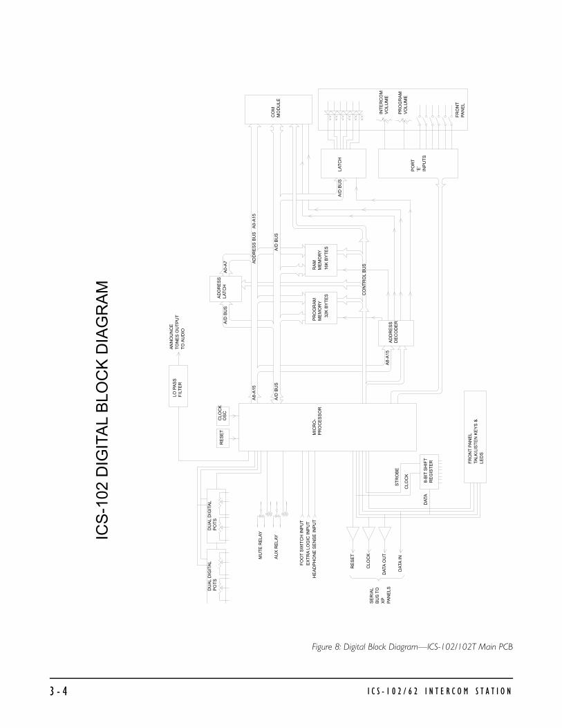
Figure 8: Digital Block Diagram—ICS-102/102T Main PCB
ICS
-102
DIG
ITA
L B
LOC
K D
IAG
RA
M
PR
OG
RA
MM
EM
OR
YR
AM
ME
MO
RY
AD
DR
ES
S B
US
A
0-A
15
A/D
BU
S
32K
BY
TE
S16
K B
YT
ES
CO
MM
OD
ULE
CO
NT
RO
L B
US
CLO
CK
OS
CR
ES
ET MIC
RO
-P
RO
CE
SS
OR
AD
DR
ES
SLA
TC
HA
0-A
7
A8-
A15
AD
DR
ES
SD
EC
OD
ER
A8-
A15
LAT
CH
PO
RT
’E’
INP
UT
S
FR
ON
TP
AN
EL
INT
ER
CO
MV
OLU
ME
PR
OG
RA
MV
OLU
ME
LO P
AS
SF
ILT
ER
AN
NO
UN
CE
TO
NE
S O
UT
PU
TT
O A
UD
IO
DU
AL
DIG
ITA
LP
OT
SD
UA
L D
IGIT
AL
PO
TS
MU
TE
RE
LAY
AU
X R
ELA
Y
FO
OT
SW
ITC
H IN
PU
TE
XT
RA
LO
GIC
INP
UT
HE
AD
PH
ON
E S
EN
SE
INP
UT
RE
SE
T
CLO
CK
DA
TA O
UT
DA
TA IN
SE
RIA
LB
US
TO
XP
PA
NE
LS
8-B
IT S
HIF
TR
EG
IST
ER
CLO
CK
DA
TA
ST
RO
BE
FR
ON
T P
AN
EL
TALK
/LIS
TE
N K
EY
S &
LED
S
A/D
BU
S
A/D
BU
S
A/D
BU
S
I C S - 1 0 2 / 6 2 I N T E R C O M S T A T I O N3 - 4

I C S - 1 0 2 / 6 2 I N T E R C O M S T A T I O N 3 - 5
Figure 9: ICS-102 Main PCB Schematic, Rev.D
8
8
7
7
6
6
5
5
4
4
3
3
2
2
1
1
D D
C C
B B
A A
D03D14D27D38D413D514D617D718
OC1CLK11
Q0 2Q1 5Q2 6Q3 9Q4 12Q5 15Q6 16Q7 19
RO 6/RO 5REF 1
SE
N7
VC
C8
RIN2
CT3
GN
D4
815714613512411310291
3
2
1
594837261 910
3
2
1
54
1415
32
1112
76
12
1311
1
23 4
56
1
23
9
108
A010A19A28A37A46A55A64A73A825A924A1021A1123A122A1326A1427
%%oCE%%o20%%oOE%%o22VPP1
O0 11O1 12O2 13O3 15O4 16O5 17O6 18O7 19
OUT 1IN3
GN
D2
3
2
1
VI
GN
D
VO
VI GN
D
VO
1
2
33
2
1
TAL08
XTAL07
/NMI18
/IRQ19
PA034PA133PA232PA331PA430PA529PA628PA727
PD020PD121PD222PD323PD424PD525
VRL51
/RE
S17
VRH52
VD
D26
MO
DA
03M
OD
B02
VS
S01
A/D0 09A/D1 10A/D2 11A/D3 12A/D4 13A/D5 14A/D6 15A/D7 16
A8 42A9 41
A10 40A11 39A12 38A13 37A14 36A15 35
AS 04E 05
R/W 06
PE0 43PE1 45PE2 47PE3 49PE4 44PE5 46PE6 48PE7 50
D0 3D1 4D2 7D3 8D4 13D5 14D6 17D7 18
OC 1G 11
Q02Q15Q26Q39Q412Q515Q616Q719
12
1311
A1B2C3
G16G2A4G2B5
Y0 15Y1 14Y2 13Y3 12Y4 11Y5 10Y6 9Y7 7
A0 10A1 9A2 8A3 7A4 6A5 5A6 4A7 3A8 25A9 24
A10 21A11 23A12 2A13 26A14 1
%%oCS%%o20%%oOE%%o22%%oWE%%o27
D011D112D213D315D416D517D618D719
9
108
4
56
R37
22 1W
R3822 1W
C25.1uF
C26.1uF
IC1274HC374
C8.1uF
C9.1uF
C1047uF16V
+IC6TL7705AP
R510K
R63.3K
R83.3K
D11N4001
D21N4001
R9100K
R1010K
K1
K2
J1
Q1
MPSA13
R11100K
R1210K
R13100K
R1410K
C11.01uF
J2 IC7D
4050
Q2
MPSA13
IC7B
4050
IC7F
4050
IC7A
4050
R39
220
R40
220
R41
220
IC7E
4050
IC7C
4050
R152.2K
R1610K
IC24D74HC00
IC24A74HC00
IC24B74HC00
IC3A74HC00
R17
1K
C121uF MONO
R18
47
R1947
C14.1uF
IC24C74HC00
R73.3K
C3.1uF
R4 10K
IC829C256
C7.01uF
C81.1uF
D3
6.8V ZD
R24
2.2KR2510K
D4 D5 D6 R26
100
D7 1N4001
IC9
LM317T
D8
1N4001R27240
R282.4K
R292.4K
R30240
R2010K
Q3MPSA13
R21470K
R22
220K
C13.022uF
R234.7K
D9
1N4001
D10 1N4001
R31
100
D11D12D13
D14
6.8V ZD
R32
2.2K
R3310K
IC10
LM337T
C15
1000uF
+
D15
1N4001
IC11
7805T
R34
22 1W
C16
100uF 25V
+
C17
100uF 25V
+
C18
100uF 25V
+
C19 220uF 25V+
C20 220uF 25V
+Q4MPSA55
Q5MPSA05
C23
4700uF+
C24
4700uF+
R35
0 ohm
C21
4700uF+
C22
4700uF
+
D17
1N5401
D16
1N5401
R110MC1
27pFC2
27pF Y18.000MHz
R2
3.3K
IC168HC11
IC274HC373
IC3D74HC00
IC474HC138
IC562C256L
R36
0 ohmF1
.90A POLY
IC3C74HC00
C4.1uFR3
3.3K
C5.1uF
IC3B74HC00
C6.1uF
+5D+5D
+5D +5D +5D
+5D
+15A-15A
+5D
+5D
+5D
+5D
+5D
+5D
+5D
+5D
+5D
+5D
+5V
+5D
+5D
+5D
+15A
+15A
+5VD-15V
+15V
LISTEN AUDIOPOT DATAPOT CLK.
POT RESET
+PRG-IN-PRG-IN
HEAD SENSETALK AUDIO
BEEP
/TALK EN
SER DATASER CLK
SER RESET
/LIST EN
A6 AD6 A0 AD0 AD0 A0A4 AD4 A1 AD1 AD1 A1A2 AD2 A2 AD2 AD2 A2A0 AD0 A3 AD3 AD3 A3A1 AD1 A4 AD4 AD4 A4A3 AD3 A5 AD5 AD5 A5A5 AD5 A6 AD6 AD6 A6A7 AD7 A7 AD7 AD7 A7
A8 A8AD0 A9 A9AD1 A10 A10AD2 A11 A11AD3 A12 A12AD4 A13 A13AD5 A14 A14AD6AD7
A8 ASA9A10A11A12 A15A13A14A15
AS A14E
R/W
PE0
PE2 EPE3 IRQPE4 R/WPE5 AD0PE6PE7 AD1
AD2
AD3
AD4
AD5
AD6
AD7
A11A12 R/W
/RST
A13 EA14A15 AS
A0
A1
A2
A3
AD0AD1AD2AD3AD4AD5AD6
PE0
PE2
PE3
PE4
PE5
PE6
PE7
VC
CG
ND
VC
CG
ND
VC
CG
ND
(A8-A15)
(A0-A7)
(AD0-AD7)
(/RD)
(/WR)
8
16
(H4000-H7FFF RAM SPACE)
20
10
14
28
14
28
7
1
2
3
4
5
6
7
8
9
10
11
12
13
14
15
16
17
18
19
20
21
22
23
24
25
26
(CONTROL BUS)
(CONTROL BUS)
/CE0
/CE1
R/W
AS
TALK AUDIO
LISTEN AUDIO
D GND.
D GND.
A GND.
A GND.
+5D
+5D
AD0
AD1
AD2
AD3
AD4
AD5
AD6
AD7
COMMUNICATIONSMODULE
TP2
TP1
(AUX. RELAY)
(MUTE RELAY)
MISC.CONNECTOR
DB-15F
HEAD SENSE INPUT
ANNOUNCE TONE OUT
FOOT SW INPUTEXTRA LOGIC INPUT
XP PANEL DATA RETURN
XP/AUDIO DATA OUTXP/AUDIO CLOCK
LOGIC GND.------LOGIC GND.------EXTRA LOGIC IN--FOOT SWITCH IN--MUTE RELAY N.C.-AUX. RELAY N.C.-MUTE RELAY WIPE-AUX. RELAY WIPE-MUTE RELAY N.O.-AUX. RELAY N.O.-
+PROGRAM INPUT--
AUDIO GND.-------PROGRAM INPUT--
XP PANEL UNREG +VOLT.-
XP PANEL UNREG +VOLT.-
XP PANEL GND. --------XP PANEL KEY DATA-----XP PANEL GND. --------
XP PANEL RESET OUT----
XP PANEL CLOCK OUT----
XP PANEL DATA OUT-----
NO CONNECT------------
TO EXTRAKEY PANELS
DB-9
POT SERIAL DATA OUTPOT SERIAL CLOCKPOT SERIAL RESET
POT SERIAL DATA OUTPOT SERIAL CLOCKPOT SERIAL RESET
HEAD SENSE INPUT
TO SHEET 2
ANALOG CIRCUITS
DATE
DATE
DATE
DWN
CHK
APP
ORCAD P/N -
PLOT SIZE -
SCALE SIZE DWG NO. REV
TITLE:SCHEMATIC
CLEAR-COMINTERCOM SYSTEMS R
DESCRIPTIONREV ECO# DATE BY CHK
05/12/93Clark McCoy
SHEET #1
D
D
--------
+15V ANALOG SUPPLY
-15V ANALOG SUPPLY
ANNOUNCE TONE OUTPUT
JP2
MUTE RELAY OUTPUT
AUX. RELAY OUTPUT
TP3
E
/RST
IRQ
XP RESETAUDIO RESET
XP/AUDIO DATA OUT
XP/AUDIO CLOCK
XP RESET
AUDIO RESET
XP/AUDIO DATA OUTXP/AUDIO CLOCK
8
1
14
27
28
29
30
31
32
33
34
A GND.
A GND.
+5D
A0
A1
A2
A3
/TALK EN
/LIST. EN
ICS-102 MAIN BOARD
EXTERNALPOWER
TRANSFORMER
14 VAC
1
2
SOURCE
SOURCE
DIGITAL SOURCE
EXTRA KEYS & LEDSON FRONT PANEL
ANS BACK DW
MIC ON
PANEL MIC
SPEAKER ON
ANS BACK DW
MIC ON
PANEL MIC
SPEAKER ON
CALL WAITING
CALL WAITING
4
2
13
7
8
14
5
6
3
1
9
11
12
10
15
16
RESET SWITCH
CWLISTENLEVEL
5K
TO SHEET 2
ANALOG CIRCUITS
710304-SCH-D-
1
2
3
4
5
6
7
8
9
10
J3
J4
J5
J6
SER DATA
SER CLOCK
+ SUPPLY
+ SUPPLY
RESET
GND.
GND.
KEY DATA
UNUSED
UNUSED
FRONTPANELSELECTKEYS
DIGITALGROUNDSOURCE
ANALOGGROUNDSOURCE
+15V
-15V
AGNDDGND
+5D
20
10
(/H3000-H37FF)
(/H3800-H3FFF)(H2000-H27FF)
(E)
(E)
RP-110K
5 3 67 4 2
1
7
14
LAST USED DESIGNATORS
C81D19F1IC24J2
K2P2R105Y1
BH
D
A RELEASE 6/16/931841
P1
SW-4
SW-3
SW-2
SW-1
R1 1K
R2 1K
R3 1K
R4 1K
R5 1K
R6 1K
D1D2
D3
D4
D5
D6
FUNCTION SWITCH PWB P/N 710306
B 2059 ADD C82 10/12/93 MP
C 2176 REVISED 12/20/95 BH
7103041D.ORC
D 2365 FLASH ROM ADDITION 04/28/97 CM
LISTEN LEVEL
LISTEN LEVEL
/RS
T
/RS
T
IRQ

I C S - 1 0 2 / 6 2 I N T E R C O M S T A T I O N 3 - 6
Figure 10:
EQ
EQ
AU
X. A
UD
IO O
PT
ION
HO
T M
IC
OU
TP
UT
SA
OU
TP
UT
SP
EA
KE
R
FE
ED
OU
T
AN
NO
UN
CE
TO
NE
FR
OM
MIC
RO
PR
OC
ES
SO
R
RS
-422
CO
M M
OD
ULE
4-W
IRE
TALK
4-W
IRE
LIS
TE
N
BA
LLA
NC
ED
PR
OG
RA
M
INP
UT
HE
AD
PH
ON
E
SP
EA
KE
RPA
NE
L
MIC
RO
PH
ON
E
HE
AD
SE
T
MIC
RO
PH
ON
E
LIM
ITE
R
MIC
RO
PR
OC
ES
SO
R
CO
NT
RO
LLE
D G
AIN
BLO
CK
MIC
RO
PR
OC
ES
SO
R
CO
NT
RO
LLE
D
AU
DIO
SW
ITC
H
ICS
-102
AU
DIO
BLO
CK
DIA
GR
AM
Loca
lS
idet
one
Adj
ust
+ -

I C S - 1 0 2 / 6 2 I N T E R C O M S T A T I O N 3 - 7
8
8
7
7
6
6
5
5
4
4
3
3
2
2
1
1
D D
C C
B B
A A
3
21
84
3
1
2134
5 12
STR1D2CLK3OE15
Q1 4Q2 5Q3 6Q4 7Q5 14Q6 13Q7 12Q8 11
QS 9%%oQS%%o10
5
67
586
913
714
1012
11
1
5
67
34
2
3
21
84
3
21
84
5
67
5
67
6
8
7
11
9
10
3
21
84
3
21
84
5
67
6
2
8
7 3
1 14
14
16
15
3
21
3
2
1
3
2
1
5
67
3
21
84
P25K POT
C45.22uF
C46.22uF
R7939.2K*
R8039.2K*
IC18ANE5532
C44100pF
R6239.2K*
C59
100pF
R7839.2K*
IC13ADG211
IC144094
C47
.1uF
C48.1uF
R71 10K
C54
100pF
R632.7K
C49
.1uF
R6510K
IC16BNE5532
D18
5.1V ZD
D19
5.1VZD
C63
.1uF
IC19ADS1267-10
10K POT
IC23BNE5532
R642.7K
C51
22uF
+
C50
22uF+
R6810K
C52
100pF
C53
100pF
IC19BDS1267-1010K POT
C72
100pF
IC16ANE5532
IC23ANE5532
R72150K
R95
10K
R10510K
R73
3K
R9010K
IC18BNE5532
C79.1uF
C80.1uF
C69.1uF
C70.1uF
C71.1uF
C73.1uF
C74.1uF
C75.1uF
C76.1uF
C77
1uF NP
R4222K
R4315K
IC17BNE5532
R44
220
C27
.01uF
R45
100
R46
82
R4722
P1 500
R48
22
R4947K
R5022K
IC13BDG211
IC13CDG211
R75
33K
R51
4.02K*
R52
4.02K*
R534.02K*
R54
4.02K*
C28
22uF
+
R5510K
C29
22uF
+
C30 .002uF
C31 .002uF
C32 .0047uF
C334.7uF
+
C55 47pF
IC17ANE5532
C34
1uF NP
C35
.1uF
C36
.1uF
C4322uF
+
C37
22uFTANT
+
R56
100
C38 22uF TANT+
C39
22uFTANT
+
R5747
R5847
C40
.002uF
C41 .0068uF
R59
4.02K*
R74150K
C42
.1uF
1 42 3
R601K
R61
4.7K
IC20ALM833
IC20BLM833
IC21LM384
-
+
C64
.1uF
R97 5.1K
R1008.2K R101
2.2
IC13DDG211
R104
10K
C67.22uF C65
.0039uF
C85
220uF
+
R99
5.1
R1030
C68
1000uF
+
Q6J174
D
S
R81
10K
R8210K
R8310K
R84470K
R94
10K
C56.047uF
C57.0047uF
C58
.1uF
R76
4.7K
R77
22K
R853.3K
R863.3K
R87
10K
R88
1.2K
R89
2.2M
C60 200pF 5%
C61
.1uF
C62
1uF NP
R91
24K
R9256K
R9310K
Q7
2N2222
Q8
2N2222
IC15BNE5532
R961M
IC15ANE5532
C82200pF
+15V
+15A
+15A
+15A
+5D
+15A
+15A
+15A
+15A+15V
+15A
+15V
+5VD
+15V
-15V
-15A
-15A
+5D
-15A
-15A
-15A-15A
-15A
-15V
-15A
+15A
LISTEN AUDIO
TALK AUDIO
BEEP
+PRG-IN
-PRG-IN
HEAD SENSE
POT DATAPOT CLK.POT RESET
SER RESET
SER DATASER CLK.
/TALK EN/LIST EN
1
2
FRONT PANELSPEAKER
1
TOMIC
PREAMP CONNECTOR
x
Y
FROMHEADSET
CONNECTOR
Y
X
MICROPHONE
HEADSET MIC.
CW
HEADPHONE
T
R
S
TO PANEL
DATE
DATE
DATE
DWN
CHK
APP
ORCAD P/N -
PLOT SIZE -
SCALE SIZE DWG NO. REV
TITLE:SCHEMATIC
CLEAR-COMINTERCOM SYSTEMS R
05/12/93Clark McCoy
SHEET #2
D
D
--------
2
1
2
(SIDETONE SW)
(PANEL SEL)(HEADSET SEL)(HEAD SIDETONE SEL)
(SA ENABLE)
LH
W
CLKDIN
DOUT/R
LH
W
(SIDETONE)(ADJUST)
16
8
(BEEP FILTER)
1
2
3
4
5
6
7
8
9
10
11
12
13
14
15
16
17
18
19
20
21
22
23
24
25
26
(TALK BUS)
ANALOG GND.
ANALOG GND.
ANALOG GND.
ANALOG GND.
TALK BUS
-15 SUPPLY
-15 SUPPLY
+15 SUPPLY
+15 SUPPLY
SA CONTROL
DIGITAL GND.
DIGITAL GND.
DIGITAL GND.
DIGITAL GND.
DIGITAL GND.
DIGITAL GND.
DIGITAL GND.
DIGITAL GND.
LINE OUTPUT
OPT-2AUXILLIARYINTERFACE
MODULE
FROM SHEET 1
FROM SHEET 1
SHEET 1TO
FROM SHEET 1
FROM SHEET 1
TO SHEET 1
(/TALK EN)(/LIST. EN)
ICS-102 MAIN BOARD
,4,5,10,
1
3
2
(PRG ENABLE)
710304-SCH-D-
J7
J8
J9
J10
J11
11,12,13
3
3
3
D
7103042D.ORC
Figure 11: ICS-102 Main PCB Schematic, Rev.D
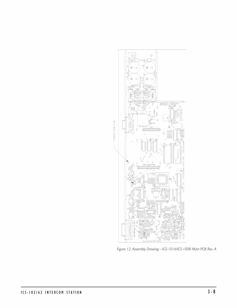
Figure 12: Assembly Drawing—ICS-1016/ICS-1008 Main PCB Rev. A
I C S - 1 0 2 / 6 2 I N T E R C O M S T A T I O N 3 - 8

Bill of Materials for ICS-102/102T Main PCB
CapacitorsValue Type Volts Tol. Part # Designator27 PF CERAMIC 50 5% 150071 C1 C247 PF CERAMIC 50 10% 150041 C55100 PF CERAMIC 50 10% 150006 C44 C52 C53 C54
C59 C72200 PF CERAMIC 100 5% 150063 C60 C826800 PF CERAMIC 50 5% 150057 C41.001 UF CERAMIC 30 20% 150052 C65 C66.0022 UF MYLAR 100 5% 150045 C30 C31 C40.0047 UF MYLAR 50 5% 150114 C32.0047 UF CERAMIC 50 10% 150016 C57.01 UF CERAMIC 30 20% 150012 C7 C11 C27.022 UF MYLAR 100 10% 150008 C13.047 UF MONO 50 10% 150111 C56.1 UF MONO 50 10% 150035 C9 C14 C25 C26 C35
C36 C47 C48 C49C58 C61 C63 C3 C4C5 C6 C8 C76 C79C80 C81 C64 C67C69 C70 C71 C73C74 C75
.1 UF MONO 100 10% 150085 C42
.22 UF MYLAR 100 20% 150003 C45 C461 UF CERAMIC 50 10% 150073 C12 C181 UF ALUMINUM NP 50 10% 150002 C3 C62 C77 C782.2 UF ALUMINUM NP 50 150065 C3322 UF TANT. 16 150032 C38 C3922 UF ALUMINUM 16 20% 150142 C28 C29 C37 C43
C50 C5133 UF ALU LOW ESR 35 20% 150130 C84 C8347 UF ALUMINUM 16 20% 150143 C10100 UF ALUMINUM 25 20% 150099 C16 C17220 UF ALUMINUM 25 150137 C19 C201000 UF ALUMINUM 35 150092 C684700 UF ALUMINUM 25 150139 C21 C22 C23 C24
I C S - 1 0 2 / 6 2 I N T E R C O M S T A T I O N3 - 9

Resistors & Resistor PacksValue Power Type Tol. Part # Designator1 OHM 1/4W CARBON FILM 5% 410139 R99 R1032.2 OHMS 1/4W CARBON FILM 5% 410113 R10122 OHMS 1/4W CARBON FILM 5% 410004 R47 R4822 OHMS 1W CARBON FILM 5% 410174 R3847 OHMS 1/4W CARBON FILM 5% 410039 R18 R19 R57 R5882 OHMS 1/4W CARBON FILM 5% 410038 R46100 OHMS 1/4W CARBON FILM 5% 410071 R26 R31 R45 R56220 OHMS 1/4W CARBON FILM 5% 410007 R39 R40 R41 R44240 OHMS 1/4W CARBON FILM 5% 410060 R27 R305 OHMS TRIM POT 470060 P11K OHMS 1/4W CARBON FILM 5% 410010 R17 R601.2 OHMS 1/4W CARBON FILM 5% 410041 R882.2K OHMS 1/4W CARBON FILM 5% 410011 R15 R24 R322.4K OHMS 1/4W CARBON FILM 5% 410103 R28 R292.7K OHMS 1/4W CARBON FILM 5% 410040 R63 R643.0K OHMS 1/4W CARBON FILM 5% 410104 R733.3K OHMS 1/4W CARBON FILM 5% 410015 R2 R3 R6 R7 R8 R85
R864.02K OHMS 1/8W METAL FILM 1% 410155 R51 R52 R53 R54
R594.7K OHMS 1/4W CARBON FILM 5% 410013 R23 R61 R765K OHMS TRIM POT 470022 P28.2K OHMS 1/4W CARBON FILM 5% 410037 R100 R10210K OHMS 1/4W CARBON FILM 5% 410016 R4 R5 R10 R12 R14
R16 R20 R25 R33R55 R65 R68 R71R81 R82 R83 R87R90 R93 R94 R95R104 R105
1 OHM X 9 R-PACK 415001 RP115K OHMS 1/4W CARBON FILM 5% 410017 R4322K OHMS 1/4W CARBON FILM 5% 410018 R42 R50 R77 R97
R98 R106 R107 R108R109
24K OHMS 1/4W CARBON FILM 5% 410083 R9133K OHMS 1/4W CARBON FILM 5% 410020 R7539.2K OHMS 1/8W METAL FILM 1% 410111 R62 R78 R79 R8047K OHMS 1/4W CARBON FILM 5% 410021 R4956K OHMS 1/4W CARBON FILM 5% 410023 R92100K OHMS 1/4W CARBON FILM 5% 410024 R9 R11 R13150K OHMS 1/4W CARBON FILM 5% 410026 R72 R74220K OHMS 1/4W CARBON FILM 5% 410028 R22470K OHMS 1/4W CARBON FILM 5% 410030 R21 R841M OHM 1/4W CARBON FILM 5% 410058 R96
I C S - 1 0 2 / 6 2 I N T E R C O M S T A T I O N 3 - 1 0

2.2M OHMS 1/4W CARBON FILM 5% 410153 R8910M OHMS 1/4W CARBON FILM 5% 410059 R1
Diodes and TransistorsDevice Description Part # DesignatorDIODE 1N957B ZENER 6.8V .4W 5% 480026 D3 D14DIODE 1N4003 RECT 1A 200PIV 480058 D1 D2 D7 D8 D9 D10 D15DIODE 1N4148 SIGNAL 10MA 75PIV 480000 D4 D5 D6 D11 D12 D13DIODE 1N5231B ZENER 5.1V .5W 5% 480038 D18 D19DIODE 1N5339 ZENER 5.6V 5W 480182 D20DIODE 1N5401 RECT 3A 100PIV 480005 D16 D17TRANSISTOR 2N2222 NPN 30V 480006 Q7 Q8 Q9 Q10 Q11
Q12TRANSISTOR J174 JFET PCHAN 8V VGS 480079 Q6TRANSISTOR MPS-A05 NPN 60V 480052 Q5TRANSISTOR MPS-A13 NPN 30V DARL 480004 Q1 Q2 Q3TRANSISTOR MPS-A55 PNP 60V 480050 Q4
Integrated CircuitsDevice Description Part # Designator4050B CMOS HEX BUFFER 480077 IC74094B CMOS 8 BIT SHIFT REGISTER 480107 IC1468HC11A CMOS MCU 52 PIN PLCC FP 480132 IC14HC00 CMOS QUAD NAND 480157 IC3 IC2474HC138 CMOS 3 TO 8 LINE DECODER 480120 IC474HC373 CMOS OCTAL D LATCH 480142 IC274HC374 CMOS OCTAL D FL/FLOP 480143 IC12DG211CJ CMOS QUAD ANALOG SWITCH 480092 IC13GM76C256L CMOS SRAM 32K X 8 100NS 480183 IC5DS1267-10 DIGITAL POT, DUAL 10K 480195 IC19LM384 OPAMP, POWER 4W 480012 IC21 IC22LM833N OPAMP, DUAL LO NOISE 480175 IC20NE5532 OPAMP, DUAL LO NOISE 480070 IC15 IC16 IC17 IC18 IC2378SR105HC REGULATOR, 5V SWITCHER 1A 480206 IC25LM317T REGULATOR, POS ADJ 1.5A 480167 IC9 LM337T REGULATOR, NEG ADJ 1.5A 480177 IC10TL7705AP RESET SUPERVISOR IC 480134 IC6
I C S - 1 0 2 / 6 2 I N T E R C O M S T A T I O N3 - 1 1

MiscellaneousDevice Description Part # DesignatorCONNECTOR 2.1MM CO-AX PC MTG POWER 210213 J4CONNECTOR DB-9F RT ANG PC MTG 210186 J2CONNECTOR DB-15F RT ANG PC MTG 210187 J1CRYSTAL 8.000MHZ PARALLEL CRYSTAL 230003 Y1FUSE 0.90A POLY SWITCH 520036 F1 JUMP JACK JUMP JAX 210103 JP2RELAY SPDT 12V PC RELAY ITT#SZ12 450006 K1 K2
I C S - 1 0 2 / 6 2 I N T E R C O M S T A T I O N 3 - 1 2

Figure 13: Schematic ICS-102/ICS-102T Selector Switch PCB Rev.B
88
77
66
55
44
33
22
11
DD
CC
BB
AA
C
00
Mon
day,
June
28,
199
9
Siz
eD
ocum
ent N
umbe
rR
ev
Dat
e:S
heet
of
D1
D8
D7
D6
D5
D4
D3
IC1
4094
IC2
4094
R3
100K
R4
100K
R5
4.7K
R6
4.7K
R8
100R
710
K
D11
C5
.001
IC678
05L
C1
.1uF
C3
.1uF
C4
.1uF
C2
4.7u
F16
V
+
IC1
4094
D9
IC3
4094
IC4B
4013
IC4A
4013
IC5B
4001
IC5C
4001
IC5D
4001
IC5A
4001
D10
R1
100K
R2
4.7K
IC2
4094
IC3
4094
D2
S8
#8S
7#7
S6
#6S
5#5
S4
#4S
3#3
S10
#10
S9
#9S
1#1
S2
#2
C3
.1uF
C2
.1uF
C1
.1uF
+5V
+5V
+5V
+5V
+5V
+5V
+5V
+5V
+5V
+5V
+5V
STR 1D 2CLK 3OE 15
Q14 Q25 Q36 Q47 Q514 Q613 Q712 Q811QS9 %%oQS%%o10
STR 1D 2CLK 3OE 15
Q14 Q25 Q36 Q47 Q514 Q613 Q712 Q811QS9 %%oQS%%o10
VI
GND
VO
STR 1D 2CLK 3OE 15
Q14 Q25 Q36 Q47 Q514 Q613 Q712 Q811QS9 %%oQS%%o10
STR 1D 2CLK 3OE 15
Q14 Q25 Q36 Q47 Q514 Q613 Q712 Q811QS9 %%oQS%%o10
D9
CLK
11Q
13
%%
oQ%
%o
12
S8 R 10
D5
CLK
3Q
1
%%
oQ%
%o
2
S6 R 4
5 64
8 910
12 1311
1 23
STR 1D 2CLK 3OE 15
Q14 Q25 Q36 Q47 Q514 Q613 Q712 Q811QS9 %%oQS%%o10
STR 1D 2CLK 3OE 15
Q14 Q25 Q36 Q47 Q514 Q613 Q712 Q811QS9 %%oQS%%o10
(DA
TA IN
)
(DA
TA O
UT
)
(+5V
SO
UR
CE
)
(GN
D. S
OU
RC
E)
UN
RE
GU
LAT
ED
+5V
DC
OU
T
LOG
IC G
ND
.O
UT
LOG
IC G
ND
.
UN
RE
GU
LAT
ED
+5V
DC
INP
UT
INP
UTC
LOC
K IN
RE
SE
T IN
LED
DA
TA IN
SW
. DA
TA O
UT
LED
DA
TA O
UT
SW
DA
TA IN
PU
T
CLO
CK
OU
T
RE
SE
T O
UT
OU
TP
UT
TO
NE
XT
E
XPA
NS
ION
I/O
PA
NE
LIN
PU
T F
RO
M S
TAT
ION
or
PR
EV
IOU
S E
XPA
NS
ION
PA
NE
L
7147
14
16
8
8
8
16
16
8
8
8
16
16
16
J1-1
J1-7
J1-3
J1-5
J1-2
J1-4
J1-6
J1-8
J2-2
J2-4
J2-6
J2-8
J2-1
J2-7
J2-3
J2-5
J3-2
J3-1
J3-3
LED
Prin
ted
Circ
uit B
oard
J1-3
RG
RG
RG
RG
RG
RG
RG
RG
RG
RG
SW1
SW2
SW3
SW4
SW5
SW6
SW7
SW8
SW9
SW10
(2.2
K)
(20
PLA
CE
S)
RE
D &
GR
EE
NLE
D P
AIR
S
UP
D
OW
N
DE
SC
RIP
TIO
NR
EV
EC
O#
DA
TE
BY
CH
K
DA
TE
DA
TE
DA
TE
DW
N
CH
K
AP
P
OR
CA
D P
/N -
PLO
T S
IZE
-
SC
ALE
SIZ
ED
WG
NO
.R
EV
TIT
LE:
SC
HE
MA
TIC
CLE
AR
-CO
MIN
TE
RC
OM
SY
ST
EM
SR
1 7 3 5 2 4 6 886425371
7201
47S
B.O
RC
1:1
C72
0147
-SC
H-C
-
ICS
-102
AS
SY
# 71
0308
R20
R1
D1
D20
109J2
-9 N
/C
J2-1
0 N
/C
9 10
J1-9
N/C J1
-10
N/C
J3-6
J3-5
J1-5
J1-6
J1-2
J1-1
J1-4
J3-4
N/CN/C
J3-8
J3-7
J1-7
J1-8
SW
ITC
H P
.C.B
. AS
SY
# 71
0253
SE
LEC
TOR
SW
ITC
H A
SY.
04/0
5/93
Cla
rk M
cCoy
B
A18
41R
ELE
AS
E6/
16/9
3B
H
B20
28C
5 W
AS
100
pF7/
13/9
3B
H
I C S - 1 0 2 / 6 2 I N T E R C O M S T A T I O N3 - 1 3

Figure 14: ICS-102/102T Selector Switch PCB Rev.D
I C S - 1 0 2 / 6 2 I N T E R C O M S T A T I O N 3 - 1 4

Bill of Materials for ICS-102 Selector Switch PCB
CapacitorsValue Type Volts Tol. Part # Designator0.001 uF Ceramic Disc 30 20% 150052 C50.1 uF Monolithic 50 10% 150035 C1 C3 C44.7 uF Aluminum 50 150087 C2
Resistors & Resistor PacksValue Power Type Tol. Part # Designator100 OHM 1/4 Carbon Film 5% 410071 R84.7K OHM 1/4 Carbon Film 5% 410013 R2 R5 R610K OHM 1/4 Carbon Film 5% 410016 R7100K OHM 1/4 Carbon Film 5% 410024 R1 R3 R4
Diodes and TransistorsDevice Description Part # DesignatorDiode 1N4148 SIGNAL 10MA 75PIV 480000 D1 D2 D3 D4 D5 D6
D7 D8 D9 D10 D11
Integrated CircuitsDevice Description Part # DesignatorLogic Chip 4001 CMOS 4 2 IN NOR GATE 480112 IC5Logic Chip 4013 CMOS DUAL D FF 480171 IC4Logic Chip 4094B CMOS SHIFT REGISTER 480107 IC1 IC2 IC3Regulator 7805L POS 5V REG. TO-92 PKG 480088 IC6
MiscellaneousDevice Description Part # DesignatorSWITCH SP3T MOM-OFF-MOM PC MTG 510080 S1 S2 S3 S4 S5 S6 S7
S8 S9 S10 S10
I C S - 1 0 2 / 6 2 I N T E R C O M S T A T I O N3 - 1 5

Figure 15: Assembly Drawing ICS-102/102T Selector Switch LED PCB Rev.A
I C S - 1 0 2 / 6 2 I N T E R C O M S T A T I O N 3 - 1 6

Bill of Materials for ICS-102/102T Selector Switch LED PCB
CapacitorsValue Type Volts Tol. Part # Designator0.1 uF Monolithic 50 10% 150035 C1 C2 C3
Resistors & Resistor PacksValue Power Type Tol. Part # Designator1K OHM 1/4 Carbon Film 5% 410010 R1-R20(20)
Integrated CircuitsDevice Description Part # DesignatorLogic Chip 4094B CMOS SHIFT REGISTER 480107 IC1 IC2 IC3
MiscellaneousDevice Description Part # DesignatorLED GREEN, ROUND, FLAT TOP LED 390045 D2 D4 D6 D8 D10
D12 D14 D16 D18D20
LED RED, ROUND, FLAT TOP LED 390044 D1 D3 D5 D7 D9D11 D13 D15 D19
I C S - 1 0 2 / 6 2 I N T E R C O M S T A T I O N3 - 1 7
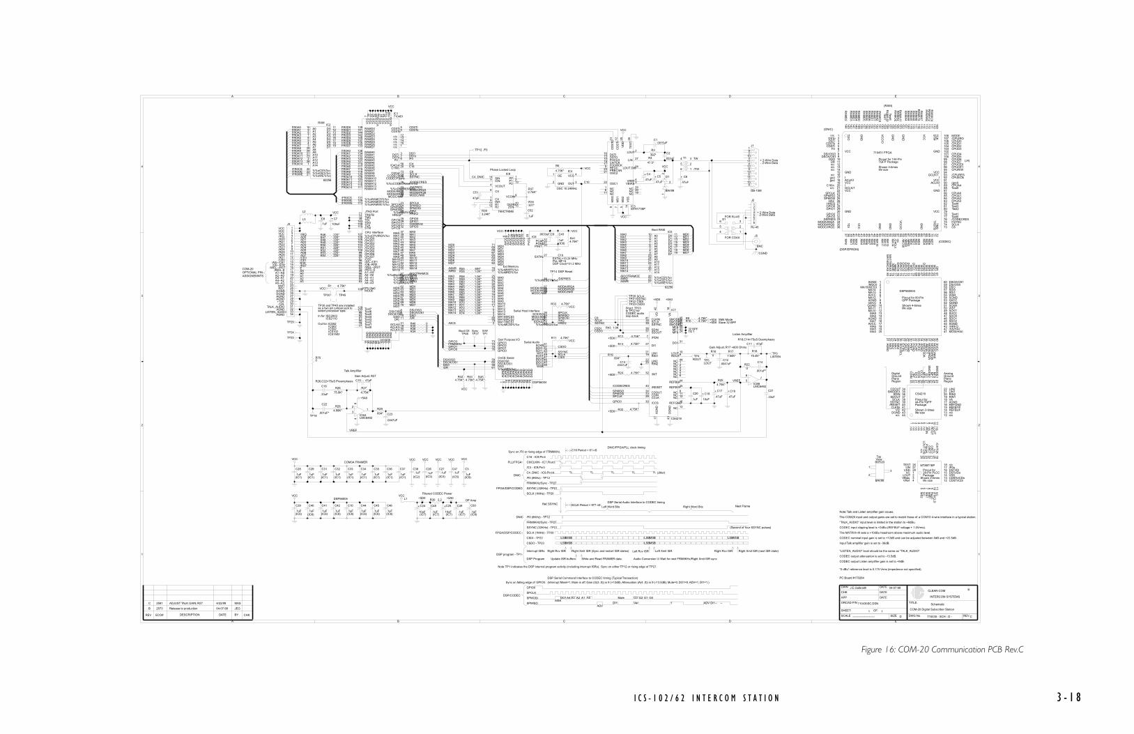
I C S - 1 0 2 / 6 2 I N T E R C O M S T A T I O N 3 - 1 8
A
A
B
B
C
C
D
D
E
E
4 4
3 3
2 2
1 1
B
C
2573
2581
Release to production
ADJUST TALK GAIN; R27
04-07-99
4/22/99
JEG
MAS Schematic
COM-20 Digital Subscriber Station
710435 - SCH - D - CD
1 1
710435SC.DSN
J.E.Galbraith 04-07-99
-----------------------REV ECO# DESCRIPTION DATE BY CHK
CHK
DWN
APP
DATE
DATE
DATE
ORCAD P/N
SHEET: OF:
SCALE SIZE DWG No. REV
TITLE:
CLEAR-COM
INTERCOM SYSTEMS
®
TP23 CSDO
R62 1.0K*
IC8ALMC6482
R47 220*
R750
C43
.1uF(IC6)
R52 220*
D1
BAV99
C38.1uF
(IC2)
C39
.1uF(IC6)
R63 1.0K*
C47.1uF
(IC5)
C51
47pF
C18
.47uF
+
L3
R53 220*
C10
.1uF(IC6)
TP5 LOUT
T1
R33 4.75K*
R40 0
R56 1.0K*
R34 0
C19
10uF
+
TP14
R54 220*
R64 1.0K*
R372.74K*
R35 0
J4
TP4 ROUT
C8
.1uF
C48
.1uF(IC7)
R65 1.0K*
C7
100uF
+
R12 4.75K*
IC7
CS4218
R36 0
R6
4.75K*
R43 1.0K
IC2
62256
C42
.1uF(IC6)
C20
.1uF
IC4
OSC 10.24MHz
IC1710451
CPU Interface
JTAG Port
(CPU Sel)
R67 1.0K*
IC3MT9171BP
R38301*
R46 220*
R25
4.75K*
R3
392*
R1 4.75K*
R4
47.5*
C1.0015uF
C4
.47uF
+
C17
.47uF
+
C5
.47uF
+
TP18
R68 1.0K*
C26.1uF
(IC3)
C2
.022uF
C6
.47uF
+
C28
.1uF(IC1)
C29
.1uF(IC1)
R393.24K*
C50
.1uF(IC8)
R69 1.0K*
C3
.1uF(IC9)
C36
.1uF(IC1)
C31
.1uF(IC1)
R9 4.75K*
C37
.1uF(IC1)
J2
RJ-45
C32
.1uF(IC1)
L1
TP24
C33
.1uF(IC1)
R70 1.0K*
IC9
74HCT4046
C24
10uF(IC7)
+
C34
.1uF(IC1)
TP25
C35
.1uF(IC1)
R71 1.0K*
J5
BNC
TP27
R32 4.75K*
C27.1uF
(IC4)
R72 1.0K*
C9.0033uF
R18
75.0K*
R220
C46
.1uF(IC6)
R17
7.50K*
C11 47pF
R73 1.0K*
R160
IC5
62256
R444.75K*
TP46
S1
IC8BLMC6482
R55 604*
C52
.1uF
R24 4.75K*
C41
.1uF(IC6)
TP3LISTEN
R414.75K*
R11 4.75K*
C12.0047uF
R74 1.0K*
R48 220*
L2
C45
.1uF(IC6)
R454.75K*
R58 1.0K*
C14
.001uF*
R29
604*
C21
.33uF
R26
75.0K*
TP12 /F0
R19604*
TP29
R49 220*
R13 4.75K*
C15 47pF
C13.0047uF
R59 1.0K*
TP30
C23
.0047uF
IC6
DSP56004
Serial Host Interface
Gen Purpose I/O
OnCE Serial
Serial Audio
Ext Memory
TP1
C16
.33uF
R50 220*
TP45
R30 2.2
C44
.1uF(IC6)
R284.99K*
R60 1.0K*
C25
10uF(IC7)
+
TP20 SCLK
C22
.001uF*
R10 4.75K*
C40
.1uF(IC6)
C49
.1uF(IC7)
TP21SSYNC
R51 220*
R424.75K*
R27
4.75K*
J1
DB-15M
TP22 CSDI
VCC VCC
VCC
VCC
VCC
VCC
+5D0
VCC VCC
+5A0
VCC
VCC
VCC
VCC
VCC
VCC
VCC
VCC
VCC
VCC
VCC
VCC
+5D0
+5A0
+5A0
+5D0
+5D0
+5D0
+5D0
+5D0
+5D0
3
21
84
12
3
16
5
34
2
123456789
10111213141516171819202122232425262728293031323334 V
A18
VD
42
CLKIN41
SSYNC39 SCLK38
/PDN7
LIN121RIN119
LIN222RIN220
CDOUT34CDIN33
/CCS30CCLK29
/INT32
/RESET40
MF6 28MF7 25MF8 24
AG
ND
17
DG
ND
43
REFGND16
REFBYP15REFBUF14
SDOUT37 SDIN36
SMODE335SMODE226SMODE123
LOUT 10ROUT9
NC 44NC 1NC 2NC 3NC 4NC 5NC 6
NC 8NC 11NC 12
NC 13
DI127 DO1 31
A010A19A28A37A46A55A64A73A825A924A1021A1123A122A1326A141
%%oCS%%o20%%oOE%%o22%%oWE%%o27
D0 11D1 12D2 13D3 15D4 16D5 17D6 18D7 19
OE1
GND2 OUT 3
VCC 4
VC
C7
VC
C19
VC
C22
VC
C42
GN
D15
GN
D30
GN
D50
GN
D54
%%oCPUIRQ%%o107CPUD0106CPUD1105CPUD2104CPUD3103CPUD4101CPUD5100CPUD699CPUD798/CE097/AS--/CE196/OE--R/W95/WEL--/RST93/RES--E92
A2--A086A3--A185A4--A284A5--A383
%%oRAMWE%%o113 %%oRAMOE%%o125 %%oRAMCS%%o131
RAMA0136RAMA1134RAMA2132RAMA3124RAMA4121RAMA5119RAMA6117RAMA7115RAMA8118RAMA9120RAMA10128
RAMD0139RAMD1141RAMD2144RAMD3142RAMD4140RAMD5137RAMD6135RAMD7133
CODECSClk74CODECFSync75
%%oCODECReset%%o76
C16In 20
C8Out 73
%%oMCS%%o59
%%oMRD%%o61%%oMWR%%o60
MD0 62MD1 63MD2 64MD3 65MD4 67MD5 68MD6 69MD7 70
A1--AS89
MA4 43MA2 40MA3 41
TRSTB71TMS72TDI38
TCK109STM110TDO143
MODE108
MA0 37MA1 39
CDSTi 5CDSTo4
DSTi 3DSTo 2
F0 6
GCLK/I 21
VC
CIO
58V
CC
79V
CC
91V
CC
94V
CC
114
VC
CIO
130
GN
D66
GN
D87
GN
D10
2G
ND
122
GN
D12
6G
ND
138
RAMA14111 RAMA13116 RAMA12112 RAMA11123
MA5 44MA6 45MA7 46MA8 47MA9 48
MA10 49MA11 51MA12 52
%%oDSPRES%%o33MODA/IRQA34MODB/IRQB35MODC/NMI36
SPCLK23SPMISO24SPMOSI25
%%oHA2%%o26HREQ27
GPIO231GPIO332
I 17ACLK/I 18ACLK/I 90
GPIO028GPIO129
/C4Out 56
%%oBootRamCE%%o57
MA13 53MA14 55
DSI/OSO8DSCK/OS19
DSO 10DR 11
Test6127 Test7129
Test588
n/c 12n/c 13n/c 14n/c 16n/c 1
Test077 Test178 Test280 Test381 Test482
CD
STO
13
CD
ST
I12
VD
D28
MS
25
DSTI16DSTO15F0/CLD10C4/TCK19F0O/RCK17REGC9PRECAN23OSC221
OSC122
MS
O8
MS
17
TE
ST
26V
SS
14
LOUT 2
LIN 27
LOUT DIS24
VREF4VBIAS 3
NC1NC6NC11 NC 18NC 20NC 25
12345678
CIN3
VCOUT4
SIN14
CX6
CX7INH5R111R212
PP 1P1 2P2 13
VCOIN9
DEMO10ZEN 15
A010A19A28A37A46A55A64A73A825A924A1021A1123A122A1326A141
%%oCS%%o20%%oOE%%o22%%oWE%%o27
D0 11D1 12D2 13D3 15D4 16D5 17D6 18D7 19
1
2
3
4
5
6
5
67
MA025MA124MA223MA322MA420MA519MA618MA716MA814MA913MA1012MA1111MA127MA135
MA15/MCS33 MA144
MD071MD169MD268MD367MD465MD564MD663MD762
MA16/MCS280MA17/MCS179
AG
ND
1A
GN
D8
QG
ND
10A
GN
D15
AG
ND
21Q
GN
D29
SG
ND
34
QG
ND
52S
GN
D44
SG
ND
54D
GN
D66
AV
CC
6Q
VC
C9
AV
CC
17Q
VC
C28
PV
CC
33
SV
CC
40
QV
CC
53S
VC
C48
DV
CC
70
DG
ND
72
PGND31
EXTAL27
PCAP32
%%oRESET%%o36
MODA/IRQA37MODB/IRQB38MODC/NMI39
%%oMRD%%o77 %%oMWR%%o78
%%oMCS0%%o2
SCK/SCL26MISO/SDA35MOSI/HA041
SS/HA242%%oHREQ%%o43
GPIO076 GPIO175 GPIO274 GPIO373
PINIT 30
DSI/OS059DSCK/OS160DSO58%%oDR%%o61 WSR55
SCKR51SDI0 57SDI1 56WST 50
SCKT49SDO047SDO146SDO245
8157
146
135
124
113
10291
C10
C10
AD2
AD4AD5
AD7
AD0/IRQ
AD6
AD1
AD3
C4_DNIC
FR0A11
/FR0OE
FR0D2
/MCS/MWR
MD1
FR0A13
MA13
MA4
MD7MA12
MD5MD4
/FR0OE
FR0A5
FR0A12
MA8MA9
MODA/IRQA
MODC/NMI
/BOOTRAMCE
/DSPRES
DSO
GPIO1
MODA/IRQA
FR0D7
MD0
MD4
FR0A9
MA4
FR0A8
MA11
FR0A0FR0A1
MD4
/RST
FR0A2
FR0A14
FR0A11
MA12
HREQ
/BOOTRAMCE
MD2
MODC/NMI
MA10
DSCK/OS1
FR0A14
MA5
MD2
MA0
FR0A1
MD6
MD1
/MRD
MA6
FR0A7
MA14
FR0A8
FR0D0
FR0D5
FR0A3
MA1
/MCS
MA7
MA11
MA12
FR0A3
FR0D4
/MRD
MD3
AS
MA5
/MRD
MA5
MD7
HREQ
MA0
/FR0WE
FR0A0
MD2
MD7
MODB/IRQB
DSCK/OS1
MA7
MODB/IRQB
FR0A5
MA13
MD5
FR0A6
FR0D3
DSTo
MA1 MD1
MD3
FR0A4
MA14
FR0A9
FR0D1
MD5
/DSPRES
/FR0WE
MD3MA6
FR0A10
MA9
FR0A4
MA6
MA11
/HA2
FR0A13
MD0
MD6
FR0A6
/CE0/CE1
A1
MA4
FRM8KHz
/FR0CS
MA9MD6
/MWR
R/W
FR0A7
GPIO1
DSO
MD0
MA10
MA10
FR0A2
E
A0
/FR0CS
FR0A10
FR0D6
DSTi
MA7
MA13/MWR
MA8
MA0
GPIO3
MA14
FR0A12
MA8
A2A3
C16
MA1
/C4
DSI/OSO
/DR
/DR
DSI/OSO
/TW
CDSTiCDSTo
/HA2
TW
MA3MA2
MA2MA3
MA3MA2
GPIO3FRM8KHz
/F0
SCLK
CSDI
SPCLK
GPIO0
C8
SPMOSI
SPCLK
GPIO0
SPMOSI
SPMISO
VREF
C8
SSYNC
/CODECRES
CSDO
GPIO0
SCLK
SSYNC
SSYNC
SPMOSI
SPMISO
CSDISCLK
/CODECRES
VREF
SPMISOSPCLK
CSDO
PC Board #170264
Boot RAM
Filtered CODEC Power
DSP56004
COM3A FRAMER
OP Amp
LSBMSB LSBMSB
Right Word BitsLeft Word Bits
LSBMSB
DSP Serial Audio Interface to CODEC timing
CSDI - TP22
CSDO - TP23
PLL MF=5DSP Clock=51.2 MHz
18192021222324252627282930313233343536
54 55 56 57 58 59 60 61 62 63 64 65 66 67 68 69 70 71 72
132131130129128127126125124123122121120
52 53
1081071061051041031021011009998979695949392919089888786
51
8584
119118117
TQFP Package
Shown 4-timeslife size
133134135136137138139140141142143144
116115114113112111110109
1011
1 2 3 4 5 6 7 8 9
121314151617
37 38 39 40 41 42 43 44 45 46 47 48 49 50
7374757677787980818283
GN
D
GN
D
GN
D
GN
D
GN
D
GN
D
VCC
VCC
VCC
VCC
VCC
VCC
GND
GND
GND
GND
VC
CIO
VC
C
VC
C
VC
CIO
GCLK/1I
I
I
I
Pinout for 144-Pin
710451 FPGA
RA
MA
8R
AM
A6
RA
MA
9R
AM
A5
RA
MA
11
RA
MA
4
/RA
MO
ER
AM
A3
RA
MA
10
RA
MA
2/R
AM
CS
RA
MA
1R
AM
D7
RA
MD
6R
AM
A0
RA
MD
5
RA
MD
0R
AM
D4
RA
MD
1R
AM
D3
RA
MD
2
n/c
DSToDSTi
CDSTiCDSTo
F0
C16In
TD
I
ACLK/IACLK/I
GCLK/1
TD
O
TM
ST
RS
TB
TCK
ST
M
MA
0
MA
1M
A2
MA
3
MA
4M
A5
MA
6M
A7
MA
8M
A9
MA
10
MA
11M
A12
/MC
S0
/MW
R/M
RD
MD
0M
D1
MD
2M
D3
MD
4M
D5
MD
6M
D7
C8SCLKFSYNC
CPUA3CPUA2CPUA1CPUA0
CPUA4
CPUEClk/CPURES
CPUR/WCPUCE1CPUCE0CPUD7CPUD6CPUD5CPUD4
CPUD3CPUD2CPUD1CPUD0/CPUIRQMODE
n/cn/c
n/c
/CODECRESMODA/IRQA
DSPRES
MODB/IRQBMODC/IRQC
SPCLKSPMISOSPMOSI
HA2HREQ
GPIO2R
AM
A7
RA
MA
13
RA
MA
12/R
AM
WE
Test7
/C4O
ut
n/c
GPIO3
RA
MA
14
n/c
Test6M
A13
MA
14
Test3Test2
Test1Test0
n/c (CODEC)
(DNIC)
(RAM)
(DSP/EPROM)
(J4)
GPIO1GPIO0
DSI/OSODSCK/OS1
DSODR
Test4
Test5
(gnd)
gndgnd
AGND
DG
ND
/HREQ
2
View
16
14
8
4
11
4030 3321 25
51
55
59
46
50
69 65 617680
AVCC
MA15/MCS3
MA6
MA
2
EX
TAL
SCKT
MA
16/MC
AS
SVCC
MO
DA
/IRQ
A
SDI1
DSCK/OS1
Shown 4-times
PG
ND
MA11
MD
5
MD
1
GP
IO1
AGND
SV
CC
/SS/HA2
MA
17/MR
AS
Top
3
20
18
9
5
1
3928 32 3624
43
54
58
45
49
70 66 627579
AVCC
/MSC0
MA7
MA
3
SC
K/S
CL
SDO0
life size
SGND
/RE
SE
T
WSR
DSI/OS0
QG
ND
MA12
MD
6
MD
2
GP
IO2
QVCC
SG
ND
MOSI/HA0
/MW
R
SOT-23
17
15
12
6
2
3827 31 3523
42
53
57
44
48
71 67 637478
QGND
DV
CC
MA8
MA4
MA
0
SDO2
Pinout for 80-Pin
QGND
MIS
O/S
DA
SCKR
QV
CC
MA13
DSO
MD
7
MD
3
GP
IO3
AGND
PC
AP
MO
DC
/NM
I
/MR
D
1
10
19
13
7
3
3726 29 3422
41
52
56
60
47
72 68 647377
DSP560004
AG
ND
DG
ND
MA9
MA5
MA
1
SDO1
BAV99
QVCC
PIN
IT
WST
SGND
MA14
MO
DB
/IRQ
B
SDI0
QFP Package
PV
CC
MA10
DR
MD
4
MD
0
GP
IO0
EXTAL=10.24 MHz
VA
DO
1
DI1
SM
OD
E1
LIN2
Digital
1 5 9
15
19
34
38
42
242832
/RESET
Ground
SDIN
n/c
n/c
n/c
AGND
/INT
MF
6
LIN1
MF
8LO
UT
11 4 8
14
18
22
37
41
232731
CLKIN
Analog
SDOUT
Region
REFGND
CD
IN
CC
LKn/c
n/c
RIN2
MF
7R
OU
T10 3 7
13
17
2136
40
44
2630
VD
Plane
SCLK
Region
REFBYP
CDOUT
/CC
Sn/c
n/c
n/c
RIN1
SM
OD
E2
/PD
N
2 6
12
16
2035
39
43
252933
DGND
Ground
SSYNC
Plane
REFBUF
SMODE3
n/c
n/c
n/c
CS4218
life size
44-Pin TQFP
Shown 3-times
Package
Pinout for
23
13
28
9
Package
26
7
Shown 2-times
18
24 5
16
11
28-Pin PLCC14
MT8971BP
life size 12
Pinout for27 17
8
25
15
6 10
4321
2021 1922
n/c
n/c
n/c
n/c
n/c
n/c
LOUTVBiasVRef
TESTLIN
VDD/F0oDSTi/DiDSTo/DoVSSCDSTo/CDoCDSTi/CDi
MS
2
MS
1M
S0
RegC
/F0/C
LD
LOU
T D
ISP
recanO
SC
1O
SC
2
/C4/TC
K
"TALK_AUDIO" input level is limited in the station to +6dBu.
Input Talk amplifier gain is set to -36dB.
CODEC input clipping level is +2dBu (REFBUF voltage + 1.0Vrms).
CODEC output attenuation is set to -13.5dB.
CODEC output Listen amplifier gain is set to +9dB.
"LISTEN_AUDIO" level should be the same as "TALK_AUDIO".
The MATRIX+III sets a +10dBu headroom above maximum audio level.
Note: Talk and Listen amplifier gain issues.
Phase Locked Loop
C16 - IC9,Pin4
/C4 - IC9,Pin3
C8/CLKIN - IC7,Pin41
DNIC/FPGA/PLL clock timing
LSBMSB LSBMSB
Ref, SSYNC
- 2-Wire Data
+ 2-Wire Data
+ 2-Wire Data
FOR COAX
CGND
FOR RJ-45
- 2-Wire Data
C16 Period = 61 nS
SCLK Period = 977 nS
PLL/FPGA
C4_DNIC - IC9,Pin14 \\\ \\\ \\\ \\\
/F0 (8KHz) - TP12
\\\DNIC
Next Frame
FPGA/DSP/CODEC
FRM8KHz/Sync - TP27
SSYNC (32KHz) - TP21
SCLK (1MHz) - TP20
(Second of four SSYNC pulses)
(Jitter)
"0 dBu" reference level is 0.775 Vrms (impedence not specified).
COM-20OPTIONAL PINASSIGNEMNTS
/RES--E
LISTEN_AUDIO
RAM
VCC
/AD7
REC
A4--A2
DGND
/AD1
VCC
AGND
/AD0
+12A
/AD3
/AS--/CE1/OE--R/W
/WEL--/RST
/AD4
AGND
-12A
XMIT
AGND
A5--A3
DGND
TALK_AUDIO
/CE0
VCC
A2--A0
/AD2
AGND
/AD6
/IRQ
A3--A1
/AD5
A1--AS
/F0 (8KHz) - TP12
SCLK (1MHz) - TP20
SSYNC (32KHz) - TP21
Sync on /F0 or rising edge of FRM8KHz.
FRM8KHz/Sync - TP27
FPGA/DSP/CODEC
DNIC
Left Rcv ISR Left Xmit ISRRight Rcv ISR Right Xmit ISR (Sync and restart ISR states) Right Xmit ISR (next ISR state)Right Rcv ISR
Write and Read FRAMER data.Update ISR buffers
DSP program - TP1Interrupt ISRs
DSP Program Audio Conversion \\\ Wait for next FRM8KHz/Right Xmit ISR sync
Talk Amplifier
Gain Adjust, R27
R26,C22=75uS Preemphasis
Boot CE S/WSync
DSP Reset
Note: TP1 indicates the DSP internal program activity (including interrupt ISRs). Sync on either TP12 or rising edge of TP27.
Gain Adjust, R17 +600 Ohms
Short TP23
loop-back
R18,C14=75uS Deemphasis
SM4 Mode
to TP22 for
TS 1Listen Amplifier
Slave 32 BPF
32 BPF
CODEC audio
as a two pin jumper jack to
In for: ISC2003ICS2110
Out for: ICS52ICS62ICS92ICS102ICS1502
select processor type.
TP30 and TP45 are installed
CODEC nominal input gain is set to +12dB and can be adjusted between 0dB and +22.5dB.
The COM20 input and output gains are set to match those of a COM10 4-wire interface in a typical station.
GPIO0
SPCLK
SPMOSI
SPMISO
DSP Serial Command Interface to CODEC timing (Typical Transaction)
Sync on falling edge of GPIO0.
ADVDI1 Ver 1 ADV DI1
MSKA3 A0 G3MuteDO1
DSP/CODECG2 G1 G0A4 A2 A1
(Interrupt Mask=1, Mute is off, Gain (G(3..0)) is 8 (+12dB), Attenuation (A(4..0)) is 9 (-13.5dB), Mute=0, DO1=0, ADV=1, DI1=1.)
-- --
Figure 16: COM-20 Communication PCB Rev.C
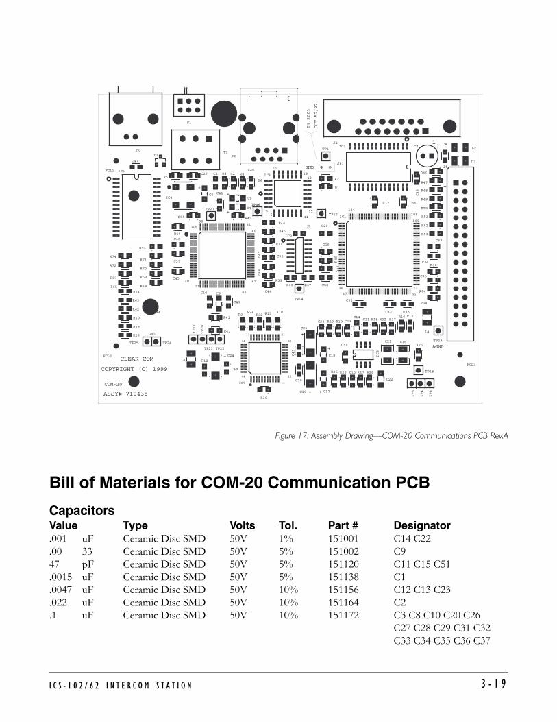
Figure 17: Assembly Drawing—COM-20 Communications PCB Rev.A
Bill of Materials for COM-20 Communication PCB
CapacitorsValue Type Volts Tol. Part # Designator.001 uF Ceramic Disc SMD 50V 1% 151001 C14 C22.00 33 Ceramic Disc SMD 50V 5% 151002 C947 pF Ceramic Disc SMD 50V 5% 151120 C11 C15 C51.0015 uF Ceramic Disc SMD 50V 5% 151138 C1.0047 uF Ceramic Disc SMD 50V 10% 151156 C12 C13 C23.022 uF Ceramic Disc SMD 50V 10% 151164 C2.1 uF Ceramic Disc SMD 50V 10% 151172 C3 C8 C10 C20 C26
C27 C28 C29 C31 C32C33 C34 C35 C36 C37
+
19
ASSY# 710435
COPYRIGHT (C) 1999
CLEAR-COM
COM-20 11
GND
21
20
+
44
34
33
12
23
22
40
41
+
8061
60
+
+
54
26
25
+ +
+
37
36
AGND
73
72
12
11
144
18
GND
108
109
1
1
R24 R13R9R10
C49
JP1
J2
IN 2003
OUT 52/92
J5
IC5
M4
R67
R72
R65
M2
R59
R58
R60
R62
R63
R64
R74
FCL2
FCL1
C52
J4
IC1
R38
C44
R68
IC6
R37
TP14
TP29
IC7
R30
C10
TP20
R12
TP23
TP21
TP24TP25
L1
X4
TP22
C24
C48
C9
R41
R43
C43
R32
TP3
TP4
TP5
R25 R26 R28C15 R27
C22
C17C19
C31
C11
IC8
R19R29C23 C13C14
C25
C18
C20
C50C16C21
R75
TP18
R35R16
C32
R22R18 R17
L4
C12
R34
R54
M3
FCL3
C8
R46
R47
C33
R49
R50
R51
R52
R53
R48
J1
R45
R44
IC3
IC9
R4C2R3C26
IC4
C1
TP27
C6
R56
R71
R69
R70
R73
C39
C45
C40
R55
C51
R33
C46
R11
C42
R42
C5
C4
C41
TP46
C27
T1
R6
D1
C47
S1
M1
C38
R1
IC2
C28
C3
R40
R39
C29
TP12
C34
C35
R36
C36C37
R2
TP1C7
L3
L2
I C S - 1 0 2 / 6 2 I N T E R C O M S T A T I O N 3 - 1 9

C38 C39 C40 C41 C42C43 C44 C45 C46 C47C48 C49 C50 C52
.33 uF Ceramic Disc SMD 25V 10% 151178 C16 C21
.47 uF Tantalum SMD 35V 10% 151184 C4 C5 C6 C17 C1810 uF Tantalum SMD 25V 10% 151192 C19 C24 C25100 uF Aluminum 16V 20% 150155 C7
ResistorsValue Power Type Tol. Part # Designator0 OHM 1/10 SMD 411100 R16 R22 R34 R35 R36
R40 R752.2 OHM 1/10 SMD 5% 411181 R3047.5 OHM 1/10 SMD 1% 411262 R4221 OHM 1/10 SMD 1% 411326 R46 R47 R48 R49 R50
R51 R52 R53 R54301 OHM 1/10 SMD 1% 411339 R38392 OHM 1/10 SMD 1% 411350 R3604 OHM 1/10 SMD 1% 411368 R29 R19 R551.00K OHM 1/10 SMD 1% 411389 R43 56 R58 R59 R60
R62 R63R64 R65 R67R68 R70 R71 R72R73R74 R69
2.74K OHM 1/10 SMD 1% 411431 R373.24K OHM 1/10 SMD 1% 411438 R394.75K OHM 1/10 SMD 1% 411454 R1 R6 R9 R10 R11
R12 R13 R24 R25 R32 4.75K OHM 1/10 SMD 1% 411454 R33 R41 R42 R44 R45
R274.99K OHM 1/10 SMD 1% 411456 R287.50K OHM 1/IO SMD 1% 411473 R1775.0K OHM 1/10 SMD 1% 411569 R26 R18
Diodes and TransistorsDevice Description Part # DesignatorDiode BAV99 DUAL DIODE... SMD 481033 D1
Integrated CircuitsDevice Description Part # Designator62256 CMOS SRAM 32K X 8 481047 IC2 IC56482 DUAL CMOS OPAMP RAIL/RAIL 481022 IC80.24MHZ CRYSTAL CLOCK OSCILLATOR 231004 IC44218 16-BIT 2 CHANNEL CODEC 481041 IC774HCT4046A CMOS PHASE LOCK LOOP...SOIC16 481045 IC9MT9171AP DIGITAL NETWORK INT. 481046 IC356004 24-BIT DSP 40MHZ 481071 IC6
I C S - 1 0 2 / 6 2 I N T E R C O M S T A T I O N3 - 2 0

IFPGA DNIC FRAMER, COM 20 710451 IC1
MiscellaneousDevice Description Part # DesignatorConnector JUMP JAX 210103 JP1Connector HEADER MULTI PIN HEADER((PER)PIN) 210112 JP1(2)Connector 15 PIN (M) RT ANG PC MTG D TYPE CON 210188 J1Connector DUAL ROW HEADER 17 POS. .230IN 210279 J4Connector RJ-45 RT ANG MOD CON 1-PORT SHIELDED210335 J2Connector BNC RT ANGLE PC MNT W/THREAD BUSH210354 J5Inductor FERRITE EMI SUPPRESSOR 400MA 181001 L1 L2 L3Switch DPDT MICRO-SUBMINIATURE SWITCH 510124 S1Transformer 2745B 2:1 PULSE TRANSFORMER 560023 T1
I C S - 1 0 2 / 6 2 I N T E R C O M S T A T I O N 3 - 2 1

I C S - 1 0 2 / 6 2 I N T E R C O M S T A T I O N3 - 2 2

SPECIFICATIONS
0 dBv is referenced to 0.775 V RMS
ICS-102/62
FRONT-PANEL CONTROLS AND CONNECTORSTalk/Listen Switches: 10 (ICS-9102, ICS-102T)
6 (ICS-62, ICS-62T)Function Keys 2 toggle keys; 4 functions Answer Back Switch 1Volume Controls 1Headset Connector 1 D4M XLRPanel Mic Connector 1-1/4 inch Phone Jack
REAR-PANEL CONNECTORSMiscellaneous DB-15FTo Matrix DB-15MAudio IO (OPT-100) DB-15F
Accessory DB-9FAC Power IEC-320
PANEL MICROPHONE INPUTType: ElectretInput Level 40 dBvImpedance 200 Ohms
HEADSET MICROPHONE INPUTType DynamicInput Level -55dBvGain Adjustment Range +/- 5dBImpedance 200 Ohms
LOCAL PROGRAM INPUTType Electronically BalancedImpedance 8k Ohms BridgingLevel 0 dBv will produce full
output of speaker when volume control is fully clockwise
4
I C S - 1 0 2 / 6 2 I N T E R C O M S T A T I O N 4 - 1

HEADPHONE OUTPUTSImpedance 50 to 600 OhmsPower 1/2 W into 50 Ohms
SPEAKER AMPLIFIER OUTPUTImpedance 8 OhmsPower 4 W
LINE INPUT (2 -PAIR LISTEN FROM MATRIX) Type Transformer BalancedImpedance 8k Ohms BridgingLevel 0 dBv nominalFreq. Resp. 100 Hz to 15 kHz +/- 2 dB
LINE OUTPUT (2-PAIR TALK TO MATRIX)Type Transformer BalancedImpedance 150 Ohms (when talk active)Level 0 dBv nominalFreq. Resp. 100 Hz to 15 kHz, +/- 2 dB
LOGIC INPUT #1Type 5 V logic with pull-up resistorLogic True = Short to Ground
LOGIC INPUT #2Type (Option 1) 5 V logic with pull-up resistorLogic (Option 1) True = Short to GroundType (Option 2) External Voltage SenseLogic (Option 2) Lo = 0 - +2 VDC, Hi = +4 - +30 VDC
MUTE RELAY Contact Type 1 pair SPDT (single form C)Contact Voltage Rating 24 VDCContact Current Rating 1 Amp continuous, 2 Amps peak at
24 VDC
STATION RELAY Contact Type 1 pair SPDT (single form C)Contact Voltage Rating 24 VDCContact Current Rating 1 Amp continuous, 2 Amps peak at
24 VDC
I C S - 1 0 2 / 6 2 I N T E R C O M S T A T I O N4 - 2
POWERAC Input to Station Between 12 and 16 VAC at 750 mA
Mains ACPower Input to Wall-Mount Transformer 16 W(150 mA at 115 VAC)
TEMPERATUREOperating Between 0 and 50 C (32 to 125 F)Storage Between 0 and 70 C (32 to 150 F)
HUMIDITYOperation and Storage Between 20% and 90%,
Non-Condensing
PACKAGE DIMENSIONSHeight 1.75 in. (44mm), 1 RUWidth 19.0 in. (483mm)Depth 6.75 in. (171mm)Weight 4.27 lbs. (2.0kg)
OPT-100 AUXILIARY AUDIO I/O OPTION
AUDIOOutput Signal Levels 0.0 dBv nominalImpedance 600 Ohms, transformer balancedFrequency Response 100 Hz to 10 kHz, +/- 2 dB of
mic preamp or external program inputDistortion Less than 0.5% THD
SA RELAY Contact Type 1 pair SPDT (single form C)Contact Voltage Rating 24 VDCContact Current Rating 1 Amp continuous, 2 Amps peak at
24 VDC
ACCESSORY PANELS
XPL-12Height 1.75 in. (44 mm), (1 RU)Width 19.0 in. (483 mm)Depth 2.50 in. (64 mm)Weight 1.5 lbs. (0.7 kg)
I C S - 1 0 2 / 6 2 I N T E R C O M S T A T I O N 4 - 3

Power 14 VAC, 0.5 Amps (120 VAC 770 mA wall-mounttransformer supplied with unit. 220 VAC version available on special order)
XPL-22Height 1.75 in. (44 mm), (1 RU)Width 19.0 in. (483 mm)Depth 2.50 in. (64 mm)Weight 1.8 lbs. (0.8 kg)Power 14 V AC, 0.5 Amps
(120 V AC 770 mA wall-mount transformer supplied with unit. 220 V ACversion available on special order).
Notice About SpecificationsWhile Vitec Group Communications makes every attempt to maintain the accuracy of the information contained in its product manuals, that information is subject to change without notice. Performance specifications included in this manual are design-center specifications and are included for customer guidance and to facilitate system installation. Actual operating performance may vary.
I C S - 1 0 2 / 6 2 I N T E R C O M S T A T I O N4 - 4

VITEC GROUP COMMUNICATIONS WARRANTY
Vitec Group Communications (VGC) guarantees this product to be free of manufacturing defects in material and workmanship under normal use for a period of two years from the date of purchase.
TECHNICAL SUPPORT To ensure complete and timely support to its customers, VGC maintains Technical Service Centers (TSC) staffed by qualified technical personnel. A Technical Service Center is staffed to respond to all technical inquiries and to troubleshoot technical problems regarding all products supplied by VGC. A TSC is fully available to VGC’s customers during the full course of their warranty period.
Instructions for reaching our Technical Service Centers are given below.
For technical support from Europe, the Middle East, and Africa
Call: +49 40 66 88 40 40 Monday through Friday 09:00 – 17:00 (GMT)
+49 40 66 88 40 41 24hrs, any day (But you must have your PIN number ready.)
Web site: www.clearcom.com (Click the 24 X 7 User Support symbol on the Web site.)
For technical support from the Americas and Asia
Call: +1 510 496 6666 or 800 VITEC USA
Web site: www.clearcom.com (Click the 24 X 7 User Support symbol on the Web site.)
Email: [email protected]
FAX: +1 510 496 6610
EXCEPTIONSThis warranty does not include damage to a product resulting from cause other than part defect and malfunction. The VGC warranty does not cover any defect, malfunction, or failure caused beyond the control of VGC, including unreasonable or negligent operation, abuse, accident, failure to follow instructions in the manual, defective or improperly associated equipment, attempts at modification and repair not approved by VGC, and shipping damage. Products with their serial numbers removed or defaced are not covered by this warranty.
Clear-Com offers 24/7
customer support.
Return authorization
numbers are required for all
returns.
Both warranty and
non-warranty repairs are
available.
5
V I T E C G R O U P C O M M U N I C A T I O N S W A R R A N T Y 5 - 1

WARRANTY REPAIRSWhile VGC will ensure complete system integrity by providing whatever support is necessary to resolve any failure covered under the terms of the warranty, the normal procedure will be to repair or replace any defective Line Replaceable Unit (LRU) that is returned to VGC during the warranty period.
A Line Replaceable Unit (LRU) is defined as: an assembly that can be safely removed from the system and readily replaced by plugging in a new unit. In the case of ancillary items such as power supplies, the entire power supply would be returned. Whereas, in the case of circuit cards, control panels, etc., only these assemblies would be returned for repair. All equipment provided by VGC is covered under the warranty.
This warranty does not include defects arising from installation (when not performed by VGC), lightning, power outages and fluctuations, air conditioning failure, improper integration with non-approved components, defects or failures of customer furnished components resulting in damage to VGC provided product.
NON-WARRANTY REPAIRSEquipment that is not under warranty must be sent prepaid to VGC. If requested, an estimate of repair costs will be issued prior to service. Once repair is approved and completed, the equipment will be shipped freight collect from the TSC.
REPLACEMENT UNITSShould VGC determine, in its reasonable discretion, that any part of a product is defective due to faulty materials or workmanship, VGC shall at its expense, repair or replace such part and return the repaired/replacement part to the customer. The provisions of this warranty shall apply to the repaired/replacement part for the unexpired portion, if any, of the warranty period.
EMERGENCY ON-SITE ASSISTANCEVGC can provide emergency on-site technical assistance in support of warranty activities. The level of support effort required will be decided on a case-by-case basis. VGC has the qualified technical staff to support any and all emergency site activities should they occur.
LIABILITYThe foregoing warranty is VGC’s sole and exclusive warranty. There are no other warranties (including without limitation warranties for consumables and other supplies), or guarantees, expressed or implied (including, without limitation, any warranties of merchantability or fitness for a particular purpose), of any nature whatsoever, whether arising in contract, tort, negligence of any degree, strict liability or otherwise, with respect to the products or any part thereof delivered
V I T E C G R O U P C O M M U N I C A T I O N S W A R R A N T Y 5 - 2

hereunder and/or with respect to any non-conformance or defect in any such product and/or part thereof delivered hereunder and/or with respect to any non-conformance or defect in any such product and/or part thereof delivered hereunder, or any other warranties or guarantees, including but not limited to any liability of VGC for any consequential and/or incidental damages and/or losses (including loss of use, revenue, and/or profits). In any event, the maximum extent of VGC’s liability to customer hereunder shall not under any circumstances exceed the cost of repairing or replacing any part(s) fount to be defective within the warranty period as aforesaid.
RETURNING EQUIPMENT FOR REPAIR All equipment returned for repair must be accompanied by:
• Documentation stating the return address, telephone number, date of purchase, and a description of the problem.
• A repair reference number.
To obtain a repair reference number, contact the appropriate Technical Service Center at the phone numbers or Web sites listed below. Our representatives will give you instructions and addresses for returning your equipment. By talking with our representatives, many problems can be resolved on the phone.
For returns from Europe, the Middle East, and Africa
Call: +49 40 66 88 40 40 Monday through Friday 09:00 – 17:00 (GMT)
+49 40 66 88 40 41 anytime, any day
(But you must have your PIN number ready)
Web site: www.clearcom.com (Click the 24 X 7 User Support symbol on the Web site.)
For returns from the Americas and Asia
Call: +1 510 496 6666 or 800 VITEC USA
Web site: www.clearcom.com (Click the 24 X 7 User Support symbol on the Web site.)
Email: [email protected]
FAX: +1 510 496 6610
V I T E C G R O U P C O M M U N I C A T I O N S W A R R A N T Y 5 - 3
WARRANTY VALIDATION To validate your warranty, fill in the information below, and mail it to your local Technical Service Center.
V I T E C G R O U P C O M M U N I C A T I O N S W A R R A N T Y 5 - 4


