Embed Size (px)
Citation preview

01ETM ISO 9001, ISO 14001 Certified
Printed in Japan
Marine Service [email protected]
Telephone :Facsimile :e-mail :
AMSTERDAM BranchTelephone :Facsimile :e-mail :
SEATTLE BranchTelephone :Facsimile :e-mail :
CODE No.7ZPNA2012FCODE No.7ZPNA2012F
DEC. 2012 Edition 6 JRCDEC. 2012 Edition 6 JRC
Not use the asbestos
For further information,contact:
URL http://www.jrc.co.jp
INSTRUCTIONINSTRUCTIONMANUALMANUAL
Echo SounderEcho SounderJFE-680JFE-680

General Information
Thank you for purchasing the JFE-680 Echo-Sounder manufactured by Japan Radio Co., Ltd. The JFE-680 conforms to the IMO (International Maritime Organization) performance standards, enabling seabed displays and digital depth displays.
Before attempting to operate this equipment, please read this instruction manual thoroughly to ensure correct and safe operation in accordance with the warning instructions and operation procedures.
You are strongly recommended to store this instruction manual carefully for future reference. In the event that you have an operational problem or malfunction, this manual will provide useful instructions.
General Information i

Before You Begin
Symbols Used In This Manual To ensure that the equipment is used safely and correctly, and that the operator and third parties are not exposed to danger or damage, pictograms are used in this manual and on the equipment itself. These pictograms are described below. Please familiarize yourself with these pictograms and the meanings they convey before reading the rest of the manual.
Failure to observe a warning indication, leading to incorrect handling, may result in death or serious injury to the operator.
Failure to observe a caution indication, leading to incorrect handling, may result in injury to the operator, or physical damage to the equipment.
Example Pictograms
This mark is intended to alert the user to the presence of precautions including danger and warning items. The picture in each mark alerts you to operations that should be carefully performed.
This mark is intended to alert the user to the presence of prohibited activity. The picture/word in/beside each mark alerts you to operations that are prohibited.
This mark is intended to alert the user to the presence of necessary instructions. The picture in each mark alerts you to operations that must be performed.
Warning Labels Warning labels are affixed to the cover of Echo sounder body. High voltage circuit exists inside the cover. Do not remove the cover. Do not attempt to remove, damage, or modify, the warning labels.
Before You Begin ii
Usage Hints
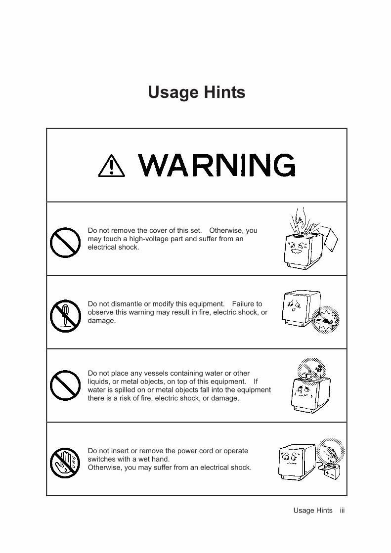
Do not remove the cover of this set. Otherwise, you may touch a high-voltage part and suffer from an electrical shock.
Do not dismantle or modify this equipment. Failure to observe this warning may result in fire, electric shock, or damage.
Do not place any vessels containing water or other liquids, or metal objects, on top of this equipment. If water is spilled on or metal objects fall into the equipment there is a risk of fire, electric shock, or damage.
Do not insert or remove the power cord or operate switches with a wet hand. Otherwise, you may suffer from an electrical shock.
Usage Hints iii

Do not damage, break or modify the power cord. When a heavy object is placed on the cord or the cord is heated, pulled, or forcibly bent, the cord will be broken resulting in a fire or an electrical shock.
Do not use this set at a voltage other than the supply voltage stated on the set. Otherwise, a fire, an electrical shock, or a failure may occur.
In the event of water of metal objects falling inside the equipment, immediately turn off the power switch, then contact JRC or its agent. There is a risk of file or electric shock if you continue to use the equipment.
If you notice smoke, unusual smells, or abnormal heat coming from the equipment, immediately turn off the power switch, then contact JRC or its agent. There is a risk of fire, electric shock, or damage if you continue to use the equipment.
There are no customer-serviceable parts inside. Unauthorized inspections and repairs could cause fires and electrical shock hazards. Please call our field representative or your nearest JRC office for inspection and repair services.
Use only the specified fuses. The use of other fuse may cause fire and/or damage. The Main switch on the CQD-2083 I/F unit must be turned off during replacing a fuse.
Usage Hints iv

Please contact JRC or its agent for the electrical installation of this equipment. Electrical installations carried out by other than the qualified staff may result in faulty operation.
Do not store or operate the equipment where subject to temperatures more than 55 or less than -15 . High temperature may cause failures.
Do not install the equipment on unstable or unleveled surfaces. Failure to observe this condition may result in the equipment falling or toppling over, resulting in injury.
If it is cold, do not move the equipment suddenly into a warm environment and switch it on. High-voltage leaks due to condensation may result in damage to the equipment. In such situations, leave the equipment in the warm environment for about 30 minutes before switching it on.
When installing the equipment, securely connect the earth lead to the earth terminal. Failure to connect the earth may result in electric shock in the event of a fault or power leak developing.
Do not turn on the equipment's power when the ship is in dry docks. Failure to observe this caution may result in damage to the transducer, etc.
Usage Hints v

When removing the power cord, be sure to remove the power cord terminal correctly. If the power cord is pulled, the cord may be damaged resulting in a fire or an electrical shock.
Do not install the units on the place being poor ventilation. Otherwise, the set that is heated may cause a fire or failure.
For safety when the equipment is to be left unused for an extended period, turn off the power switch.
When turning on the power, be sure not to press any operator panel key at the same time. Alternates to the hardware configuration of the until could cause the unit to malfunction.
Take care when laying the transducer cable, power cable, and earth lead as positioning has an affect on electromagnetic interference. There is a risk of interfering with other equipment or the echo-sounder being interfered with by the other equipment.
After installing the echo-sounder, turn on the power to all other equipment to check for interference with or from all the equipment. Interference may cause malfunctions.
Use only the specified fuses. The use of other fuse may cause fire and/or damage. The Main switch on the CQD-2083 I/F unit must be turned off during replacing a fuse.
Handle the paper cutter carefully not to cut your hand.
Usage Hints vi

External View
External View vii
Explanation of Terms
Beam angle: The angle that sound waves spread out from the transducer. Sound waves spread out in a conical manner taking the center of the bottom surface of the transducer at the apex of the cone.
Bubbling: The phenomenon where the image of the seabed is interrupted due to air bubbles caused by the ship's hull or the propeller during a voyage.
IMO: abbreviation for the International Maritime Organization.
MED: abbreviation for the Marine Equipment Directive. This is the directive for marine equipment in Europe. This directive unifies format approval standards implemented separately by each European.
NMEA0183: formats for the National Marine Electronics Association. NMEA0183 is the format used when sending or receiving depth, position, water temperature, ship speed and other information between marine equipment.
STC: Sensitivity Time Control is used for reduce shallow water clutter. Shallow seabed echo is strong and deep seabed echo is weak. So, the STC controls the sensitivity to normalize seabed echo for precision seabed tracking.
Transducer: Device that emits ultrasonic waves in water and receives the signals reflected off the seabed. This is equivalent to an antenna on a radio.
UTC: abbreviation for the Universal Time Coordinated.
Explanation of Terms viii

Contents
General Information ....................................................................................................Before You Begin .........................................................................................................Usage Hints ..................................................................................................................External View ...............................................................................................................Explanation of Terms ..................................................................................................1. Introduction ..............................................................................................................
1.1 Function .........................................................................................................….1.2 Feature ...........................................................................................................….1.3 Components .......................................................................................................1.4 Construction ......................................................................................................1.5 System Configuration ........................................................................................
2. Control Panel ...........................................................................................................3. Display ................................................................................................................…..
3.1 Standard mode (dual frequency) ......................................................................3.2 History mode ................................................................................................…..3.3 Docking mode ................................................................................................…
4. Operation ..................................................................................................................4.1 Basic Operations ................................................................................................ Turning Power ON/OFF [PWR/PANEL]…………………………………………... Adjusting Control Panel Illumination [PWR/PANEL]………………………….. Adjusting Screen Brilliance [BRILL]……………………………………………... Range Control [RANGE+][RANGE-]……………………………………………… Gain Control [GAIN+][GAIN-]……………………………………………………… Selecting Display Mode [MODE]…………………………………………………. Selecting Display Color of Day/Night [DAY/NIGHT]………………………….. Displaying Menu [MENU]…………………………………………………………... Registering Setting [ENT]………………………………………………………….. Cancelling Menu [CLR]…………………………………………………………….. Printing [PRINT]……………………………………………………………………… Stopping Buzzer [ACK]…………………………………………………………….. Up and Down Key Cursor [CURSOR] ………………………………………….... Right and Left Key Cursor [CURSOR] …………………………………………...4.2 Menu List……………………………………………………………………………….4.3 Display Setting ................................................................................................... Selecting Image Scrolling Speed………………………………………………… Noise Suppression……….…………………………………………………………. Interference Rejection…….……………………………………………………….. Setting Auto Gain……………………………………………………………………. Setting Auto Range…………………………………………………………………. Setting FWD/AFT Draft…………….……………………………………………….. Setting Cursor Display………………………………………………………………4.4 Alarm Setting………………………………………………………………………….. Setting Buzzer Key………………………………………………………………….. Setting Relay…………………………………………………………………………. Setting Depth Alarm………………………………………………………………… Setting System Alarm……………………………………………………………….4.5 Initial Setting………………………………………………………………………….. Setting Memory Length……….……………………………………………………. Setting Display Color of Day/Night………………………………………………. Setting Depth Display………………………………………………………………
iii
iiivii
viii11123567789
10101010101011121212121313131314151717171718181819202020212325252526

Setting Primary (Secondary) Transducer………………………………………. Setting Adjustment of Date and Time…………………………………………… 4.6 Printer Control Setting……………………………………………………………… Setting Print Output………………………………………………………………… Setting Print Mode………………………………………………………………….. Setting Log Book Print ……………………………………………………………. Setting Log Output Length………………………………………………………... Setting Transfer Speed…………………………………………………………….. Setting Printer Model Selection…………………………………………………… 4.7 Communication Setting…………………………………………………………….. Setting Depth Output………………………………………………………………. Setting Alarm Output………………………………………………………………. Setting System Output…………………………………………………………….. Setting Printer Port Output……………………………………………………….. 4.8 Master Reset ......................................................................................................
5. Installation ................................................................................................................5.1 Installing the Recorder Unit .......................................................................……
Flush-Mount Equipment……………………………………………………………Wall-Mount Equipment………………………………………………………………….
5.2 Installing the Transducer .................................................................................. NKF-341……………………………………………………………………………………NKF-345……………………………………………………………………………………NKF-392C………………………………………………………………………………….
5.3 Connecting Components .................................................................................. 6. Maintenance & Check.............................................................................................. 6.1 Daily Maintenance………………………………………………………………….. 6.2 Maintenance Function……………………………………………………………... Executing Self Test………………………………………………………………... Displaying Alarm Log……………………………………………………………... Outputting Alarm Log……………………………………………………………... Deleting Alarm Log………………………………………………………………… Executing Line Monitor…………………………………………………………… Displaying RX Monitor…………………………………………………………….. Displaying System No. …………………………………………………………… 6.3 Replacing Printer Paper…................................................................................ 6.4 Replacing Backup Battery................................................................................ 6.5 Troubleshooting ............................................................................................... 6.6 Replacing Fuses .............................................................................................. 6.7 Repair Parts………………………………………………………………………….. 7. Consider Installation ............................................................................................... 8. After-sales Service ..................................................................................................
8.1 When Requesting Servicing ............................................................................. 8.2 Recommendations for Inspection and Maintenance...................................... 8.3 Warranty & After-sales Service…………………………………………………….
9. Disposal ..............................................................................................................….. 9.1 Disposal of this equipment .........................................................................…..
10. Specifications ..................................................................................................….. Appendix ....................................................................................................…………... Noise ……………………………………………………………………………………….. Actual pictures……………………………………………………………………………. Seabed quality change…………………………………………………………………... Abrupt-sloped seabed …...……………………………………………………………… China Rohs…………………………………………………………………………………
2729303030333333333434343737373839394041414243444545464648484849494950515354555657575758595960616162636466
Information ...................................... Please refer to ‘Place of Contact’ on back cover.
1. Introduction
1.1 Function The JFE-680 Echo-Sounder consists of a transducer mounted on the bottom of the ship's hull and a main unit that displays information on the depth and formation of the seabed. This information is gained by using ultrasonic waves sent from the transducer that are then reflected off the sea bottom and picked up again by the transducer. The JFE-680 also has the following functions: (1) depth alarm, (2) power fail alarm, (3) output of depth data, (4) output of depth and power fail alarms.
1.2 FeatureThe JFE-680 features the following:
• Three display modes; standard, history, and docking. • Depth data for last 24 hours in memory to play back the past sounding information. • Dual frequency mode and two transducers are available in option. (*requires an optional equipment)
Conforms to the IMO Performance Standard • When the depth becomes shallower than a previously set value, a depth alarm is issued by
buzzer and LCD display. • When power is cut to the main unit, a power fail alarm is issued by buzzer and LCD display. • Contact signals can be output for both depth and power fail alarms. • Data on depths can be output.
Digital Depth Display • No need for time-consuming reading of depths using a scale against the profile of the
seabed on the paper! The current depth can be seen at a glance.
Self-Diagnostic Functions • Self-diagnostic functions can be selected from a menu, improving ease of maintenance.
1. Introduction 1

1.3 ComponentsThis section lists the components.
Standard Equipment
Name Type No. Qty. Remarks JRC Echo Sounder JFE-680 1 Matching box (primary) AW-154F 1 200kHz Transducer (primary) NKF-341 1 200kHz (with cable 20,30,40m) Spare parts 7ZXNA2002 1 Fuse 3, Printer paper Instruction manual 7ZPNA2012A 1
Option
Name Type No. RemarksMatching box(secondary)
AW-154F 200kHzAW-154F-50 50kHz or 50kHz-A
Transducer (secondary) NKF-341 200kHz (with cable 20,30,40m)NKF-345 50kHz or 50kHz-A(with cable 20,30,40m)NKF-392C 200kHz (with cable 20m)
Flush mounting KitBRBX05351 Color : MUNSELL N4 BRBX05355 Color : MUNSELL 7.5BG7/2 BRBX05354 Color : MUNSELL 2.5G7/2
Table mounting kit BRBX05340
1. Introduction 2
JFE-680-25 JFE-680-22 JFE-680-25 JFE-680-25 JFE-680-55
50kHz or 50kHz-A
50kHz or 50kHz-A
50kHz or 50kHz-A

1.4 Construction
Equipment Outline The following shows the external dimensions of the JFE-680.
1. External Dimension of JFE-680
2. Dimensions of AW-154F/AW-154F-50 Matching box
1. Introduction 3
Unit : mm
Mass : 7kg
Unit : mm
Mass : 4kg

External Dimensions of Transducer mounting The external dimensions illustrated below are for the standard equipment. Please refer to the separately supplied drawings if your specifications are not standard.
1. NKF-341/NKF-345 (Installed on ship’s bottom)
2. NKF-392C (Installed on ship’s bottom)
1. Introduction 4
Unit : mm
Mass : 22kg
Unit : mm
Mass : 41kg

1.5 System Configuration
1. Introduction 5

2. Control Panel This section describes the names and functions of the control panel and its controls.
Figure 2-1 Control Panel
No. Name Function 1 ACK Cancels the buzzer. 2 MENU Displays the menu. 3 Move a cursor. 4 ENT Selects an item. 5 MODE Switches the display modes. 6 CLR Clears an item.
7
PWR/PANEL Switches the equipment power on and off. Turn on : Hold down the PWR/PANEL key for 3 seconds. Turn off : Hold down the both the PWR/PANEL and
the BRILL keys for 3 seconds. Adjusts the control panel brilliance in power-on state
8 BRILL Adjusts the screen brilliance. 9 DAY NIGHT Enhances the visibility of the screen.
10 PRINT Starts printing or Data output. 11 (RANGE) +/– Switches the depth range to shallow or deep. 12 (GAIN) +/– Adjusts the sensitivity high or low.
2.Control Panel 6
12 11 2 1
3
4
6 5
10 9 8 7

3. Display
3.1 Standard mode (dual frequency) Standard mode displays real time sounding echoes.
Note : LAT/LON display needs to connect position data. 3. Display 7
Depth cursor
*
By primary and secondary transducer setting, dual display data will change position. FWD sounding data is displayed on the right side.
Please see page 27

3.2 History mode History mode displays past 12hour or 24 hour depth graph and real time sounding.
Note : LAT/LON display needs to connect position data.
3. Display 8
Keel height value
*

3.3 Docking mode Docking mode displays depth data.
Note : LAT/LON display needs to connect position data. 3. Display 9
*
A F T : 2 0 0 k H z F W D : 5 0 k H z
By primary and secondary transducer setting, dual display data will change position. FWD sounding data is displayed on the right side.
Please see page 27

4. Operation 10
4. Operation
4.1 Basic Operation
Turning Power ON/OFF [PWR/PANEL] To turn on power, press the [PWR/PANEL] key for about three seconds.
To turn off power, press the [PWR/PANEL] key and the [BRILL] key for about three seconds.
Adjusting Control Panel Illumination [PWR/PANEL] On echo sounder working, press the [PWR/PANEL] key, the brightness level is displayed in the bar graph.
The brightness of the operation panel changes into nine stages including OFF.
Whenever the key is pressed, a white part in the bar graph increases
and brightness goes up.
Whenever the key is pressed, a black part in the bar graph
increases and brightness goes down.
Press the [CLR] key or leave it for ten seconds, the bar graph is not displayed.
Adjusting Screen Brilliance [BRILL] On echo sounder working, press the [BRILL] key, the brightness level is displayed in the bar graph.
The brightness of the LCD display changes into ten stages excluding OFF.
Whenever the key is pressed, a white part in the bar graph
increases and brightness goes up. Whenever the key is pressed, a black part in the bar graph
increases and brightness goes down.
Press the [CLR] key or leave it for ten seconds, the bar graph is not displayed.
Range Control [RANGE+] [RANGE-] The range change of this equipment is seven stages of 10, 20, 50,100,200,500,800m.
Whenever [RANGE +] key is pressed, the range is switched to the deep end.
Whenever [RANGE-] key is pressed, the range is switched to shallow one.
Keep pressing [RANGE+] key and [RANGE-] key to the setting of auto range at the same time for about
three seconds. Moreover, auto range can be set from the menu. (Refer to 4.3 Display Setting.)
When auto range setting it, “AUTO" is displayed on the screen. However, when the manual operation is set,
nothing is displayed.
When you release auto range, press [RANGE+] key or [RANGE-] key.
After auto range releases it, it operates by range when releasing it. It doesn't return to range before setting
auto range.
Note Sea bottom might not be displayed according to the setting of draft.
When sea bottom is not displayed, depth is not displayed.

4. Operation 11
Gain control [GAIN+] [GAIN-] Gain can be set to 31 stages of 0 30.
Whenever [GAIN+] key is pressed, the sensitivity is raised.
Whenever [GAIN-] key is pressed, the sensitivity is lowered.
Keep pressing [GAIN+] key and [GAIN -] key to the setting of auto range at the same time for about three
seconds. Moreover, auto gain can be set from the menu. (Refer to 4.3 Display Setting.)
When an auto gain is set, the sensitivity setting on the screen is displayed as GAIN:AUTO". When the
manual operation is set, "GAIN: the level value" is displayed.
When you release an auto gain, press [GAIN+] key or [GAIN-] key .
After auto gain releases it, it operates by sensitivity when releasing it. It doesn't return to sensitivity before
setting auto gain.
About the sensitivity setting Note that the obstacle might be caused to sounding when the setting of sensitivity is inappropriate.
The reflection from sea bottom is different according to the condition of sea bottom. The reflection
weakens like sand and mud, etc. though a strong reflection returns like the bedrock.
It becomes impossible to recognize sea bottom when the reflection is weak and the depth value might
not be displayed. For this case, bottom of the sea is displayed in red by raising sensitivity. However, dirt
and the plankton, etc. in the sea are mistaken when sensitivity is raised too much for sea bottom, it
recognizes, and a wrong depth value might be displayed.
As for the setting of sensitivity, extent to which sea bottom is displayed by a red or an orange color is
proper.
Note When setting to an auto gain, the STC curve becomes “LONG" regardless of the setting of STC.
(Refer to 4.5 Setting Primary (Secondary) Transducer.)
Sensitivity is too low. When sea bottom is a red or an orange color, the display sensitivity is proper.
Sensitivity is too high.

4. Operation 12
Selecting Display Mode [MODE] Each time you press the MODE key, the display mode changes.
Single frequency: Each time you press the MODE key, the display mode changes as follows. Standard mode History mode Docking mode
Dual frequency: Each time you press the MODE key, the display mode changes as follows. Single frequency standard mode (primary), Single frequency standard mode (secondary), Dual frequency standard mode, Single frequency history mode (primary), Single frequency history mode (secondary), Docking mode
Notes: 1. There is not Dual frequency history mode. 2. At “Dual frequency standard mode” and “Docking mode”, each time you press the ENT
key, you can switch the settable receiver sensitivity between “primary” and “secondary”.
Selecting Day/Night Display Color [DAY/NIGHT] Whenever the key is pressed, it changes with DAY1 DAY2 NIGHT1 NIGHT2.
Each color "Image color and character color" of DAY1/DAY2/NIGHT1/NIGHT2 can be individually set by
the menu. (Refer to 4.5 Initial Setting.)
Displaying Menu [MENU] This key uses for setting the various menu functions. Detail settings are written in section 4.3 to 4.7.
DISPLAY ALARM INITIAL PRINTER CONT COMMUNICATION MAINTENANCE
Registering Setting [ENT] This key uses with menu functions.
When dual frequency using, this key is used for selecting the connection (primary or secondary) to which
sensitivity can be set while usually operating (dual frequency standard mode and docking mode).
The current selected item is displayed by a yellow character.
Selecting items move a yellow display pressing or key.
When or [ENT] key is pressed after a necessary item is
selected, a set menu of the item is displayed.
When it returns to the normal screen, press [CLR] key.

4. Operation 13
Cancelling Menu [CLR] This key uses with menu functions.
When it keeps pressing the key while printing, the printer is canceled printing.
Printing [PRINT]
This key uses for print or the data output.
The printer setting is set on PRINT MODE" menu.
(Refer to 4.6 Printer Control Setting.)
Stopping Buzzer [ACK]
The buzzer sound stops when the key is pressed after the alarm generated, and the alarm is displayed
on the screen. However, it keeps outputting the relay contact output while phenomenon is continuing.
One key pressing deals with one alarm generation factor. And, it deals with the generation of all alarm
factor under pressing about three seconds.
Up and Down Key Cursor [CURSOR] When it is a standard mode
When the key is pressed, the depth cursor is moved to shallow one and it moves accelerating
when keeping pressing it.
When the key is pressed, the depth cursor is moved to the deep end and it moves accelerating
when keeping pressing.
Depth at the cursor position is displayed on the depth cursor.
The cursor display is set by CURSOR" menu. (Refer to 4.3 Display Setting.)
The depth of the depth cursor doesn't display below the decimal point at 100m or more.
The depth cursor disappears when the range is switched, and the depth cursor exceeds the display
range. However, when either key is pressed, the depth cursor is displayed the under the depth scale
again.
When it is a history mode Whenever the key is pressed, the drawing time of the history is lengthened. (four stages of 3hr
6hr 12hr 24hr)
Whenever the key is pressed, the drawing time of the history is shortened. (four stages of 24hr
12hr 6hr 3hr)
When menu is displayed When the key is pressed, the item above the menu is selected or a set value is changed.
When the key is pressed, the item under the menu is selected or a set value is changed.

4. Operation 14
Right and Left Key of Cursor [CURSOR ] When it is a history mode
When the key is pressed, a position cursor is moved left, and it moves accelerating when
keeping pressing it.
When the key is pressed, a position cursor is moved right, and it moves accelerating when
keeping pressing it.
The cursor display is set by CURSOR" of the menu. (Refer to 4.3 Display Setting.)
Information of a time point to which a position cursor is displayed is displayed in the screen.
Display information: Depth/Draft/Keel correction/Date/Time/Latitude Longitude
The position where a position cursor is displayed doesn't scroll and is fixed. Therefore, when the
history screen scrolls, display information is updated.
When menu is displayed
key When there is a hierarchy (submenu) below, the menu of the hierarchy (submenu) is
displayed.
When setting the date etc, move the input position.
key While displaying the main menu, it becomes an error. However, while displaying the
submenu, the setting is not changed and it returns to the previous screen by one.
When setting the date etc, move the input position.
When screen brightness (BRILL)/operation panel brightness (PANEL) is adjusted
Whenever the key is pressed, brightness goes up.
Whenever the key is pressed, brightness goes down.

4. Operation 15
4.2 Menu List Menu Tree 1
Default settings shown in underline

4. Operation 16
Menu Tree 2
Default settings shown in underline
4. Operation 17
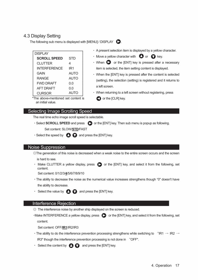
4.3 Display Setting The following sub menu is displayed with [MENU] / DISPLAY .
DISPLAY SCROLL SPEED STD CLUTTER 4 INTERFERENCE IR1 GAIN AUTO RANGE AUTO FWD DRAFT 0.0 AFT DRAFT 0.0 CURSOR AUTO
Selecting Image Scrolling Speed The real time echo image scroll speed is selectable.
Select SCROLL SPEED and press or the [ENT] key. Then sub menu is popup as following.
Set content: SLOW/STD/FAST
Select the speed by and press the [ENT] key.
Noise Suppression The generation of this noise is decreased when a weak noise to the entire screen occurs and the screen
is hard to see. Make CLUTTER a yellow display, press or the [ENT] key, and select it from the following, set content. Set content: 0/1/2/3/4/5/6/7/8/9/10
The ability to decrease the noise as the numerical value increases strengthens though “0" doesn't have
the ability to decrease.
Select the value by and press the [ENT] key.
Interference Rejection The interference noise by another ship displayed on the screen is reduced.
Make INTERFERENCE a yellow display, press or the [ENT] key, and select it from the following, set
content.
Set content: OFF/IR1/IR2/IR3
The ability to do the interference prevention processing strengthens while switching to IR1 IR2
IR3" though the interference prevention processing is not done in OFF".
Select the content by and press the [ENT] key.
A present selection item is displayed by a yellow character.
Move a yellow character with or key.
When or the [ENT] key is pressed after a necessary
item is selected, the item setting content is displayed.
When the [ENT] key is pressed after the content is selected
(setting), the selection (setting) is registered and it returns to
a left screen.
When returning to a left screen without registering, press
or the [CLR] key. *The above-mentioned set content isan initial value.
4. Operation 18
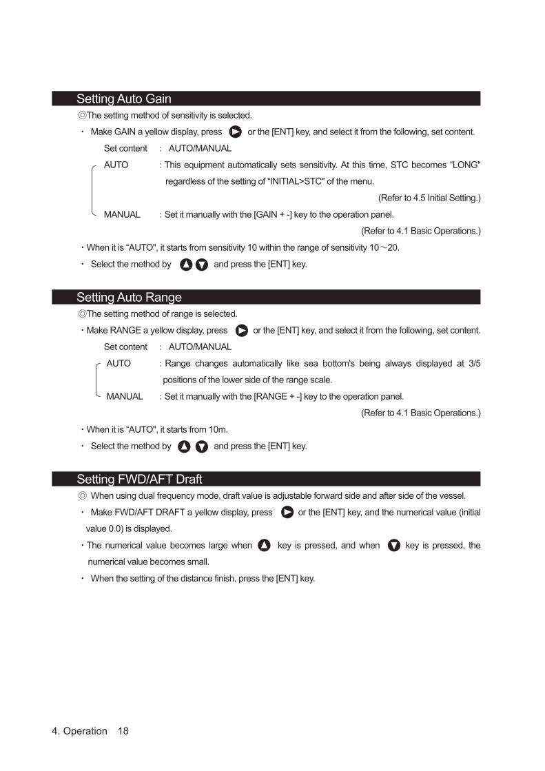
Setting Auto Gain The setting method of sensitivity is selected.
Make GAIN a yellow display, press or the [ENT] key, and select it from the following, set content.
Set content AUTO/MANUAL
AUTO This equipment automatically sets sensitivity. At this time, STC becomes “LONG"
regardless of the setting of “INITIAL>STC" of the menu.
(Refer to 4.5 Initial Setting.)
MANUAL Set it manually with the [GAIN + -] key to the operation panel.
(Refer to 4.1 Basic Operations.)
When it is “AUTO", it starts from sensitivity 10 within the range of sensitivity 10 20.
Select the method by and press the [ENT] key.
Setting Auto Range The setting method of range is selected.
Make RANGE a yellow display, press or the [ENT] key, and select it from the following, set content.
Set content AUTO/MANUAL
AUTO Range changes automatically like sea bottom's being always displayed at 3/5
positions of the lower side of the range scale.
MANUAL Set it manually with the [RANGE + -] key to the operation panel.
(Refer to 4.1 Basic Operations.)
When it is “AUTO", it starts from 10m.
Select the method by and press the [ENT] key.
Setting FWD/AFT Draft When using dual frequency mode, draft value is adjustable forward side and after side of the vessel.
Make FWD/AFT DRAFT a yellow display, press or the [ENT] key, and the numerical value (initial
value 0.0) is displayed.
The numerical value becomes large when key is pressed, and when key is pressed, the
numerical value becomes small.
When the setting of the distance finish, press the [ENT] key.

4. Operation 19
Setting Cursor Display The cursor display method in a standard mode and a history mode is selected.
Make CURSOR a yellow display, press or the [ENT] key, and select it from the following, set content.
Set content OFF/ON/AUTO
OFF When the cursor key is operated, it makes an error of the cursor without displaying it.
ON Whenever the cursor key is operated, the cursor is displayed.
AUTO When the cursor key is operated, the cursor is displayed for 30 seconds. It doesn't
display afterwards. When the cursor key is pressed again, it is displayed at the
position.
Select the method by and press the [ENT] key.
4. Operation 20
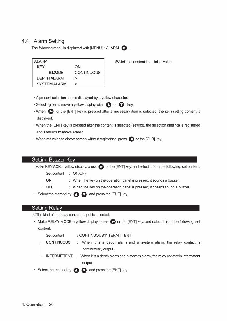
4.4 Alarm Setting
The following menu is displayed with [MENU] ALARM .
ALARM KEY ON
MODE CONTINUOUS DEPTH ALARM > SYSTEM ALARM >
A present selection item is displayed by a yellow character.
Selecting items move a yellow display with or key.
When or the [ENT] key is pressed after a necessary item is selected, the item setting content is
displayed.
When the [ENT] key is pressed after the content is selected (setting), the selection (setting) is registered
and it returns to above screen.
When returning to above screen without registering, press or the [CLR] key.
Setting Buzzer Key Make KEY ACK a yellow display, press or the [ENT] key, and select it from the following, set content.
Set content ON/OFF
ON When the key on the operation panel is pressed, it sounds a buzzer.
OFF When the key on the operation panel is pressed, it doesn't sound a buzzer.
Select the method by and press the [ENT] key.
Setting Relay The kind of the relay contact output is selected.
Make RELAY MODE a yellow display, press or the [ENT] key, and select it from the following, set
content.
Set content CONTINUOUS/INTERMITTENT
CONTINUOUS When it is a depth alarm and a system alarm, the relay contact is
continuously output.
INTERMITTENT When it is a depth alarm and a system alarm, the relay contact is intermittent
output.
Select the method by and press the [ENT] key.
A left, set content is an initial value.

4. Operation 21
Setting Depth Alarm Make DEPTH ALARM a yellow display, press or the [ENT] key, and the following menu is
displayed.
DEPTH ALARM ALARM CONT OFF DEPTH SETTING 0.0
ALARM CONT The operation of the depth alarm is selected.
Make ALARM CONT a yellow display, press or the [ENT] key, and select it from the following, set
content.
Set content OFF/ON
OFF The depth alarm doesn't operate.
ON When sea bottom becomes shallower than the depth set by "DEPTH SETTING", the
depth alarm starts.
When sea bottom becomes deeper than a set value after the depth alarm starts, it
releases.
Select the operation by and press the [ENT] key.
DEPTH SETTING
Depth where the depth alarm starts is set.
Make DEPTH SETTING a yellow display, press or the [ENT] key, and the numerical value (initial
value 0.0) is displayed.
The numerical value becomes large when key is pressed, and when key is pressed, the
numerical value becomes small.
Depth can be set up to 99.9m by a 0.1m unit.
When depth is set and the depth alarm is made “ON", the depth alarm mark is displayed at the set depth
position on the right of the range scale. This mark is not displayed to make the depth alarm “OFF".
After the depth setting finishes, press the [ENT] key.
<Example>
When the alarm depth is set to 10.0m, alarm starts by 9.9m though it doesn't start by 10.0m.
Selecting items move a yellow display with or key.

4. Operation 22
Setting System Alarm Make SYSTEM ALARM a yellow display, press or the [ENT] key, and the following menu is
displayed.
SYSTEM ALARM DEPTH LOST OFF TX ALARM OFF RX ALARM OFF BUBBLE ALARM OFF PRINTER ALARM ON
DEPTH LOST The alarm operation when sea bottom cannot be detected is selected.
Make DEPTH LOST a yellow display, press or the [ENT] key, and select it from the following, set
content.
Set content OFF/ON
OFF The sea bottom lost alarm doesn't operate.
ON When sea bottom was not able to be detected 15 times or more, the sea bottom lost
alarm is started.
When sea bottom was not able to be detected 40 times or more with range of
10/20/50m, the sea bottom lost alarm is started.
When sea bottom is detected after the sea bottom lost alarm starts, it is released.
Select the operation by and press the [ENT] key.
TX ALARM
When the transmitter becomes abnormal, the alarm operation is selected.
Make TX ALARM a yellow display, press or the [ENT] key, and select it from the following, set
content.
Set content OFF/ON
OFF The transmission alarm doesn't operate.
ON When abnormality occurs in the transmitter, the transmitter alarm is started.
Select the operation by and press the [ENT] key.
Selecting items move a yellow display with or key.

4. Operation 23
RX ALARM
When the receiving signal becomes abnormal, the alarm operation is selected.
Make RX ALARM a yellow display, press or the [ENT] key, and select it from the following, set
content.
Set content OFF/ON
OFF The receiving signal alarm doesn't operate.
ON When abnormality occurs in the receiving signal, the receiving signal alarm is started.
Select the operation by and press the [ENT] key.
BUBBLE ALARM When sea bottom cannot be detected by the influence such as bubbles, the alarm operation is selected.
Make BUBBLE ALARM a yellow display, press or the [ENT] key, and select it from the following, set
content.
Set content OFF/ON
OFF The bubble alarm doesn't operate.
ON When sea bottom was not able to be detected ten times or more, the bubble alarm is
started.
When sea bottom was not able to be detected 30 times or more with range of
10/20/50m, the bubble alarm is started.
When sea bottom is detected after the bubble alarm starts, it is released.
Select the operation by and press the [ENT] key.
PRINTER ALARM When the printer becomes abnormal, the alarm operation is selected.
Make PRINTER ALARM a yellow display, press or the [ENT] key, and select it from the following,
set content.
Set content OFF/ON
OFF The printer alarm doesn't operate.
ON When the data of "No paper" is received from the printer, printer alarm is started.
Moreover, when it becomes impossible to communicate with the printer,
"Communication abnormality" alarm is started.
However, when the printer is not connected at the time of turning on the power
supply, this item is not displayed.
When normally returning after the printer alarm starts, it is released.
Select the operation by and press the [ENT] key.
Please refer to next page for the relation between each alarm and the screen alarm display.

4. Operation 24
Each Alarm and Alarm Display (Screen Display) list
No. Alarm Alarm Display (Screen Display)
01 Primary depth alarm DEPTH1(ALR)
02 Secondary depth alarm DEPTH2(ALR)
03 Primary sea bottom lost DEPTH1(LOST)
04 Secondary sea bottom lost DEPTH2(LOST)
05 Primary transmission abnormality TX1(LEVEL)
06 Primary receiving abnormality RX1(LEVEL)
07 Primary bubbling RX1(BUBBLE)
08 Secondary transmission abnormality TX2(LEVEL)
09 Secondary receiving abnormality RX2(LEVEL)
10 Secondary bubbling RX2(BUBBLE)
11 No thermal paper PRINT(PAPER)
12 Printer communication abnormality PRINT(DATA)
13 Back-up data abnormality PROC(SRAM)
This alarm No. is also used in Alarm Log function. (Refer to page 48)

4. Operation 25
4.5 Initial Setting
The following menu is displayed with [MENU] INITIAL .
INITIAL MEMORY LENGTH 24hr COLOR DEPTH DISPLAY MODE TRAN PRIMARY SECONDARY DATE/TIME
A present selection item is displayed by a yellow character.
Selecting items move a yellow display with or key.
When or the [ENT] key is pressed after a necessary item is selected, the item setting content is
displayed.
When the [ENT] key is pressed after the content is selected (setting), the selection (setting) is registered
and it returns to above screen.
When returning to above screen without registering, press or the [CLR] key.
Setting Memory length The memory length of the sounding data displayed in the history mode is set.
Make MEMORY LENGTH a yellow display, press or the [ENT] key, and select it from the following,
set content.
Set content 12hr/24hr
12hr The memorizing length is set to 12 hours. (Memorizing interval is 30 seconds.)
24hr The memorizing length is set to 24 hours. (Memorizing interval is 1 minute.)
Select the length by and press the [ENT] key.
Setting Display Color of Day/Night When switching with the [DAY/NIGHT] key, the image color and the character color are set.
Make COLOR a yellow display, press or the [ENT] key, and the menu under the left is displayed.
COLOR DAY1 DAY1 SCREEN 2DAY2 CHARACTER 1NIGHT1 NIGHT2
After the item is selected with or key,when key is pressed, a right menu isdisplayed. As for a set menu of DAY1 NIGHT2, thesame content is displayed.
A left, set content is an initial value.

4. Operation 26
DAY1 / DAY2 / NIGHT1 / NIGHT2 Make SCREEN or CHARACTER a yellow display, press or the [ENT] key, and the number of 1 6 is
displayed.
Select a color tone of the favor number with or key and press the [ENT] key because each
content of characters is shown in the following.
SCREEN (image color) CHARACTER (character color) 1 : Background color: Black Sea bottom color: B/W 8 steps
1 : White 2 : Background color: Blue Sea bottom color: Red 8 steps 2 : Green 3 : Background color: Black Sea bottom color: Red 8 steps 3 : Yellow 4 : Background color: White Sea bottom color: Red 8 steps 4 : Gray 5 : Background color: Blue Sea bottom color: Red Brown 8 steps 5 : Navy blue 6 : Background color: Black Sea bottom color: Amber 8 steps 6 : Amber
Setting Depth Display The standard when the depth value is displayed is selected.
Make DEPTH DISPLAY MODE a yellow display, press or the [ENT] key, and select it from the
following, set content.
Set content SURF/TRAN/KEEL
SURF The record and the depth value in which the draft adjusted value is considered are
displayed.
TRAN The record and the depth value right under oscillator element are displayed.
KEEL The record and the depth value in which the keel correction value is considered are
displayed.
Select the standard by and press the [ENT] key.

4. Operation 27
Setting Primary (Secondary) Transducer Various settings concerning the installation of the transducer are selected.
Make PRIMARY or SECONDARY a yellow display, press or the [ENT] key, and the following menu
is displayed.
PRIMARY FREQ OFF POS FWD (AFT) STC LONG INNER OFF KEEL 0.0
FREQ (Frequency) Make FREQ a yellow display, press or the [ENT] key, and select it from the following, set content.
Set content OFF/200kHz/50kHz or 50kHz-A
OFF When transducer is not connected with a primary (secondary) side, it selects.
200kHz When transducer of 200kHz is connected with a primary (secondary) side, it selects.
50kHz or When transducer of 50kHz or 50kHz-A is connected with a primary (secondary) side,
50kHz-A it selects.
Select the content by and press the [ENT] key.
POS (Installation position) Make POS a yellow display, press or the [ENT] key, and select it from the following, set content.
Set content FWD/ MID/ AFT
FWD When primary (secondary) side transducer is installed at the forward, it selects.
MID When primary (secondary) side transducer is installed at the center, it selects.
AFT When primary (secondary) side transducer is installed at the after, it selects.
Select the installation position by and press the [ENT] key.
Note : On Primary and Secondary transducer settings, when select the transducer position as primary
200kHz position to AFT and secondary 50kHz or 50kHz-A position to FWD, standard dual display
mode and docking mode display is changed to right side FWD data .
For example, primary: 200kHz, AFT and
secondary 50kHz or 50kHz-A FWD,
standard dual and docking mode displays right
side is secondary data.
A left, set content is an initial value, and SECONDARY is the
same content. However, it is an initial value of SECONDARY
in ( ).
Selecting items move a yellow display with or key.
Primary: 200kHz AFT Secondary: 50kHz FWD

4. Operation 28
STC (STC curve) Make STC a yellow display, press or the [ENT] key, and select it from the following, set content.
Set content SHORT/MIDDLE/LONG
SHORT 40log is selected by the STC curve on a primary (secondary) side.
MIDDLE 30log is selected by the STC curve on a primary (secondary) side.
LONG 20log is selected by the STC curve on a primary (secondary) side.
Select the curve by and press the [ENT] key.
The STC curve is set to “LONG" regardless of the setting by here when setting it to an auto gain.
INNER (Inner hull offset) Make INNER a yellow display, press or the [ENT] key, and select it from the following, set content.
Set content OFF/1/2/3/4/5
OFF The offset of inner Hull is not put on a primary (secondary) side.
1 The offset of +4dB is set to the gain on a primary (secondary) side.
2 The offset of +8dB is set to the gain on a primary (secondary) side.
3 The offset of +12dB is set to the gain on a primary (secondary) side.
4 The offset of +16dB is set to the gain on a primary (secondary) side.
5 The offset of +20dB is set to the gain on a primary (secondary) side.
Select the content by and press the [ENT] key.
KEEL (Keel correction) Make KEEL a yellow display, press or the [ENT] key, and the numerical value (initial value 0.0) is
displayed.
The numerical value becomes large when key is pressed, and when key is pressed, the
numerical value becomes small.
The keel correction can be set in 0.1m unit within the range of 0.0 9.9m.
When the setting of the correction value finishes, press the [ENT] key.

4. Operation 29
Setting Adjustment of Date and Time Date/Time/Time difference/GPS synchronization is set.
Make DATE/TIME a yellow display, press or the [ENT] key, and the following menu is displayed.
DATE/TIME DATE TIME DIFF +00:00 GPS SYNC OFF
DATE (Date) Make DATE a yellow display, press or the [ENT] key, and Day/Month/Year is displayed.
The display of yellow is moved to the position set with key, and it sets with or key.
The numerical value becomes large when key is pressed, and when key is pressed, the
numerical value becomes small.
When the setting at the date finishes, press the [ENT] key.
TIME (Time) Make TIME a yellow display, press or the [ENT] key, and Hour: Minute: Second is displayed.
The display of yellow is moved to the position set with key, and it sets with or key.
The numerical value becomes large when key is pressed, and when key is pressed, the
numerical value becomes small.
When the setting at the time finishes, press the [ENT] key.
DIFF (Time difference) Make DIFF a yellow display, press or the [ENT] key, and Hour: Minute: Second is displayed.
The display of yellow is moved to the position set with key, and it sets with or key.
When key is pressed, the sign is changed from - to + , and the numerical value become a large.
When key is pressed, the sign is changed from + to - , and the numerical value become a small.
When the time difference is “±0", it is recognized as UTC.
When the setting of the time difference finishes, press the [ENT] key.
GPS SYNC (GPS synchronization) Make GPS SYNC a yellow display, press or the [ENT] key.
Set content OFF/ON
OFF An internal clock is used.
ON When an internal clock and the ZDA data have shifted for 30 seconds or more by using
the ZDA sentence, an internal clock is corrected.
Select the synchronization by and press the [ENT] key
A left, set content is an initial value.
Selecting items move a yellow display with or key.

4. Operation 30
4.6 Printer Control Setting Note: JFE-680 electrically stores last 12or 24hours depth data. Printer runs after only
your [PRINT] pressing.
The following menu is displayed with [MENU] PRINTER CONT .
Setting Print Output This item selects the [PRINT] key function ON or OFF.
Select “PRINTER” with or key. Then press or the [ENT] key to enter the detail setting.
Detail item OFF/ON
OFF The print key is invalidated.
ON The print key is validated.
Select the item by or key. Then press the [ENT] key.
Setting Print Mode This item selects print out mode by three items.
Select “PRINT MODE” with or key. Then press or the [ENT] key to enter the detail setting.
Detail item COPY/HISTORY/LOG
COPY
HITORY
LOG
(Refer to 4.7 communication setting.)
Select the item by or key. Then press the [ENT] key.
Note: Please read a detailed explanation of the each print mode item with next page.
PRINTER CONT PRINTER ONPRINT MODE COPY LOG BOOK PRINT OFF LOG LENGTH 10min SPEED 4800bps
PRINTER MODEL SLECTION BUILD-IN
A present selection item is displayed with a yellow
character.
To select items, use or key to choose.
Press or the [ENT] key after the item selection,
the detail setting will displayed.
Press the [ENT] key after the detail setting selection.
Then the settings would be registered and the menu
would return to previous screen.
To return to a previous screen without registering,
press or the [CLR] key.
The above-mentioned set contentis an initial value.
The item function is different according to the setting of
“COMMUNICATION > PRINTER PORT OUT" of the menu.
4. Operation 31
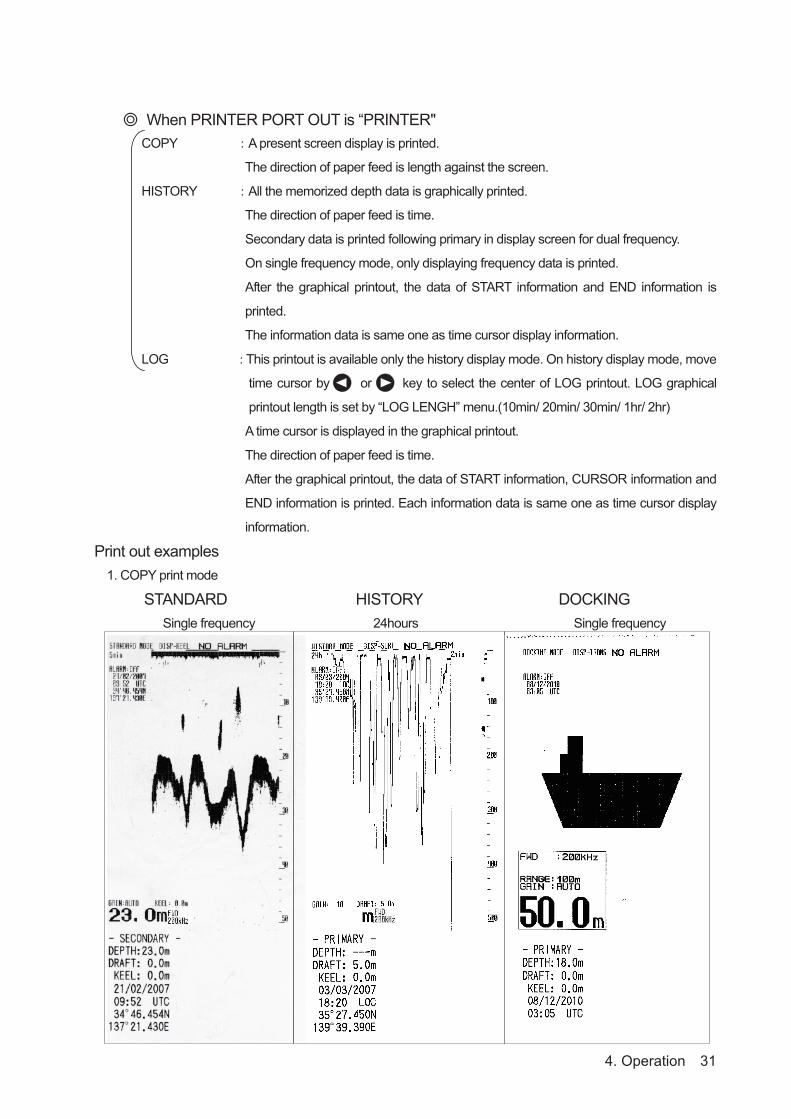
When PRINTER PORT OUT is “PRINTER" COPY A present screen display is printed.
The direction of paper feed is length against the screen.
HISTORY All the memorized depth data is graphically printed.
The direction of paper feed is time.
Secondary data is printed following primary in display screen for dual frequency.
On single frequency mode, only displaying frequency data is printed.
After the graphical printout, the data of START information and END information is
printed.
The information data is same one as time cursor display information.
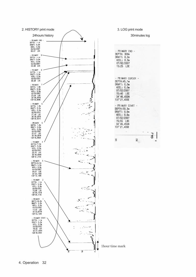
LOG This printout is available only the history display mode. On history display mode, move
time cursor by or key to select the center of LOG printout. LOG graphical
printout length is set by “LOG LENGH” menu.(10min/ 20min/ 30min/ 1hr/ 2hr)
A time cursor is displayed in the graphical printout.
The direction of paper feed is time.
After the graphical printout, the data of START information, CURSOR information and
END information is printed. Each information data is same one as time cursor display
information.
Print out examples 1. COPY print mode
STANDARD HISTORY DOCKING Single frequency 24hours Single frequency
4. Operation 32
2. HISTORY print mode 3. LOG print mode
24hours history 30minutes log
1hour time mark

4. Operation 33
When PRINTER PORT OUT is “PC"COPY Data cannot be output.
When the print or the data output is operated, it becomes an error.
HISTORY Memorized all data and maintenance system information are output.
LOG This data output is available only the history display
mode. Data and maintenance system information in
the same time as the case of above-mentioned
“PRINTER" LOG are output.
Setting Log Book Print This item selects automatic LOG book print mode.
When select this interval setting menu to 0.5min*, 1min, 2min, 5min, 10min,
depth data will automatically print with every selected interval. * 0.5min
interval is available only MEMORY LENGTH setting as 12 hours. If 24 hours
is set, 0.5min runs 1min interval. “OFF” stops automatic LOG book print
mode.
NOTE: When GPS position data is connected to JFE-680, LAT/LON
position data would print.
Select “LOG BOOK PRINT” with or key. Then press or
the [ENT] key to enter the automatic LOG book print interval setting.
Detail item OFF/0.5min/1min/2min/5min/10min
Select the output length by and press the [ENT] key.
Setting Log Output LengthThis item selects LOG output length on the HISTORY display mode with LOG print mode.
Select “LOG LENGTH” with or key. Then press or the [ENT] key to enter the detail
setting.
Detail item 10min/20min/30min/1hr/2hr
Select the output length by and press the [ENT] key.
Setting Transfer SpeedThis item selects data output baud rate. Only 4800bps is suitable to paper print. If you set other baud
rate, unusual characters might print out. This item is used with 4.7 communication setting/printer port out :
PC.
Select “SPEED” with or key. Then press or the [ENT] key to enter the detail setting.
Detail item 4800bps/9600bps/19200bps/38400bps
Select the baud rate by and press the [ENT] key.
Setting Printer Model Selection This item selects printer model from BUILD-IN/ NKG-91/ DPU-414. On JFE-680 when select NKG-91 or
DPU-414 printer disconnect build-in printer cable.

4. Operation 34
4.7 Communication SettingThe following menu is displayed with [MENU] COMMUNICATION .
COMMUNICATION DEPTH ALL ALARM ON SYSTEM ON PRINTER PORT OUT PRINTER
A present selection item is displayed by a yellow character.
Selecting items move a yellow display with or key.
When or the [ENT] key is pressed after a necessary item is selected, the item setting content is
displayed.
When the [ENT] key is pressed after the content is selected (setting), the selection (setting) is registered
and it returns to above screen.
When returning to above screen without registering, press or the [CLR] key.
Setting Depth OutputMake DEPTH a yellow display, press or the [ENT] key, and select it from the following, set content.
Set content Ver1.5/Ver2.3/ALL
Ver1.5 Setting of DEPTH DISPLAY MODE in “INITIAL" of the menu;
Only SDDBS" is output for SURF .
Only SDDBT" is output for TRAN .
Only SDDBK" is output for KEEL .
Ver2.3 SDDPT" is output.
ALL Both content of “Ver1.5" and “Ver2.3" are output at the same time.
PJRCU" is output as for each setting of “Ver1.5/Ver2.3/ALL".
Select the content by and press the [ENT] key.
Setting Alarm OutputMake ALARM a yellow display, press or the [ENT] key, and select it from the following, set content.
Set content OFF/ON
OFF When warning starts, the ALR sentence is not output. (Data as the history remains.)
ON SDALR" is output for all items of alarm setting “ON" in the alarm setting menu by a
period for one second.
Select the content by and press the [ENT] key.
A left, set content is an initial value.
4. Operation 35
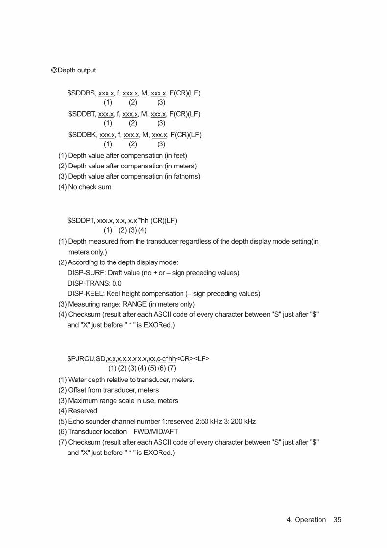
Depth output
$SDDBS, xxx.x, f, xxx.x, M, xxx.x, F(CR)(LF) (1) (2) (3) $SDDBT, xxx.x, f, xxx.x, M, xxx.x, F(CR)(LF) (1) (2) (3) $SDDBK, xxx.x, f, xxx.x, M, xxx.x, F(CR)(LF) (1) (2) (3) (1) Depth value after compensation (in feet) (2) Depth value after compensation (in meters) (3) Depth value after compensation (in fathoms) (4) No check sum
$SDDPT, xxx.x, x.x, x.x *hh (CR)(LF) (1) (2) (3) (4) (1) Depth measured from the transducer regardless of the depth display mode setting(in meters only.) (2) According to the depth display mode:
DISP-SURF: Draft value (no + or – sign preceding values) DISP-TRANS: 0.0 DISP-KEEL: Keel height compensation (– sign preceding values)
(3) Measuring range: RANGE (in meters only) (4) Checksum (result after each ASCII code of every character between "S" just after "$"
and "X" just before " * " is EXORed.)
$PJRCU,SD,x.x,x.x,x.x,x.x,xx,c-c*hh<CR><LF> (1) (2) (3) (4) (5) (6) (7) (1) Water depth relative to transducer, meters. (2) Offset from transducer, meters (3) Maximum range scale in use, meters (4) Reserved (5) Echo sounder channel number 1:reserved 2:50 kHz 3: 200 kHz (6) Transducer location FWD/MID/AFT (7) Checksum (result after each ASCII code of every character between "S" just after "$"
and "X" just before " * " is EXORed.)

4. Operation 36
Alarm output
$SDALR,hhmmss.ss,xxx,A,A,c--c*hh<CR><LF>(1) (2) (3)(4)(5) (6)
(1) Time of alarm condition change,UTC (2) ID number of the alarm source
351 primary depth alarm 352 secondary depth alarm 353 primary depth lost 354 secondary depth lost 356 printer paper is not good 357 printer connection is not good 360 primary transmit signal is not good 361 primary receive signal is not good 362 primary bottom echo signal is not good 363 secondary transmit signal is not good 364 secondary receive signal is not good 365 secondary bottom echo signal is not good 366 backup data area is not good
(3) Alarm condition (A = threshold exceeded, V = not exceeded) (4) Alarm's acknowledge state (A = acknowledged, V = unacknowledged) (5) Alarm's description text (6)Checksum (result after each ASCII code of every character between"S" just after"$" and
"X" just before " * " is EXORed.)

4. Operation 37
Setting System Output Make SYSTEM a yellow display, press or the [ENT] key, and select it from the following, set content.
Set content OFF/ON
OFF Maintenance system information is not output with the constant period.
ON Maintenance system information is added to the depth output port and it outputs.
Select the content by and press the [ENT] key.
Setting Printer Port Output Make PRINTER PORT OUT a yellow display, press or the [ENT] key, and select it from the following,
set content.
Set content PRINTER/PC
PRINTER The signal for the printer control is output.
PC Maintenance system information is output to the printer port.
The output content follows the setting of menu “PRINTER CONT>PRINT MODE".
(Refer to 4.6 Printer Control Setting.)
Select the content by and press the [ENT] key.
Maintenance menu operation is written in “6.2 Maintenance Function”
4.8 Master ResetThe buzzer sounds when turning on the power while pressing the [MENU] key and the [CLR] key at the
same time and master reset is executed. All set values except the date and time return to the factory
shipment value.
When master reset is completed, the following screen is displayed. Please do connection setting of transducers. OFF
200kHz 50kHz
A primary transducer is set on this screen. When the [ENT] key is pressed after the frequency of the
connected transducer is selected, it changes into the primary transducer setting menu of the initial setting
menu.
Refer to 4.5 Initial Setting on page 27 for the following setting methods.
When turning on the power for the first time after installing it, this screen is displayed.

5. Installation
When installing the equipment, securely connect the earth lead to the earth terminal.Failure to connect the earth may result in electric shock in the event of a fault or power leak developing.
Do not install or operate the equipment where subject to temperatures 55°C or higher or –15°C or lower. Failure to observe this caution may result in fire or damage.
Do not install the equipment on unstable or unlevel surfaces. Failure to observe this condition may result in the equipment falling or toppling over, resulting in injury.
Take care when laying the transducer cable, power cable, and earth lead as positioning has an affect on electromagnetic interference. There is a risk of interfering with other equipment or the echo-sounder being interfered with by the other equipment.
After installing the echo-sounder, turn on the power to all other equipment to check for interference with or from all the equipment. Interference may cause malfunctions.
5. Installation 38

5.1 Installing the Recorder Unit
Flush-Mount Equipment
Figure 3-1
5. Installation 39
Uni
t : m
m

Wall-Mount Equipment
Figure 3-2
5. Installation 40
Uni
t : m
m

5.2 Installing the TransducerThe external dimensions illustrated below are for the standard equipment. Please refer to the separately supplied drawings if your specifications are not standard.
NKF-341
5. Installation 41
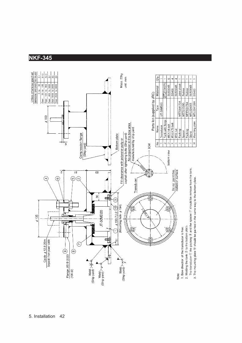
NKF-345
5. Installation 42

NKF-392C
5. Installation 43

5.3 Connecting Components
Notes:1. The shield of each cable must be securely attached to the connectors and must not
contact any other connectors, etc. 2. Casings must be grounded securely to the ship’s hull using copper plates. 3. The exterior is to be grounded to the ship’s hull cable bands. 4. Select NC/NO for Depth Alarm, System Alarm and Power Fail Alarm.
5. Installation 44

6. Maintenance & Check 45
6. Maintenance & Check
Do not open the equipment to inspect or repair internal circuits.
Inspection or repairs by anyone other than a specialized technician may result in
fire, electrical shock, or malfunction.
If internal inspection or repair is necessary, contact our service center or agents.
6.1 Daily Maintenance The life of the equipment depends on the execution situation of the daily maintenance and check. We would
recommend regularly checking usually to always keep the best. As a result, the equipment can be prevented
from breaking down beforehand.
Please execute the check shown in the table regularly.
Maintenance and check method When you check the equipment, turn off the power by all means.
No. Item Method 1 Cleaning For the main unit, wash off dirt by lightly wiping it with a dried and soft cloth. Never use a plastic solvent such as thinner and benzine. 2 Loosening of parts Check the screw and the nut for loosening, and tighten correctly.
3 Cable connection Check the connections such as cables and the connectors between equipment, and ensure the connection.
4 Fuse When the power supply fuse is blown, replace it after thoroughly investigating the cause.
Use the fuse of the cylindrical glass (included in the spare parts).
6. Maintenance & Check 46
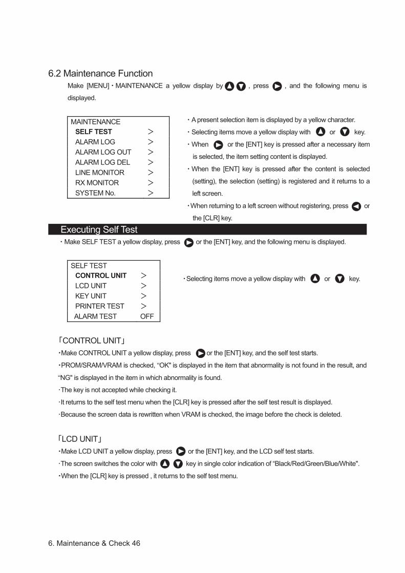
6.2 Maintenance FunctionMake [MENU] MAINTENANCE a yellow display by , press , and the following menu is
displayed.
MAINTENANCE SELF TEST ALARM LOG ALARM LOG OUT ALARM LOG DEL LINE MONITOR RX MONITOR SYSTEM No.
Executing Self Test Make SELF TEST a yellow display, press or the [ENT] key, and the following menu is displayed.
SELF TEST CONTROL UNIT LCD UNIT KEY UNIT PRINTER TEST
ALARM TEST OFF
CONTROL UNITMake CONTROL UNIT a yellow display, press or the [ENT] key, and the self test starts.
PROM/SRAM/VRAM is checked, “OK" is displayed in the item that abnormality is not found in the result, and
“NG" is displayed in the item in which abnormality is found.
The key is not accepted while checking it.
It returns to the self test menu when the [CLR] key is pressed after the self test result is displayed.
Because the screen data is rewritten when VRAM is checked, the image before the check is deleted.
LCD UNITMake LCD UNIT a yellow display, press or the [ENT] key, and the LCD self test starts.
The screen switches the color with key in single color indication of “Black/Red/Green/Blue/White".
When the [CLR] key is pressed , it returns to the self test menu.
A present selection item is displayed by a yellow character.
Selecting items move a yellow display with or key.
When or the [ENT] key is pressed after a necessary item
is selected, the item setting content is displayed.
When the [ENT] key is pressed after the content is selected
(setting), the selection (setting) is registered and it returns to a
left screen.
When returning to a left screen without registering, press or
the [CLR] key.
Selecting items move a yellow display with or key.

6. Maintenance & Check 47
KEY UNITMake KEY UNIT a yellow display, press or the [ENT] key, and the operation unit self test starts.
When the key on the operation panel is pressed, the name of the pressed key is displayed.
However, it returns to the self test menu when the [CLR] key is pressed, and the [CLR] key is judged.
PRINTER TESTMake PRINTER TEST a yellow display, press or the [ENT] key, and the test pattern is output (print).
ALARM TESTMake ALARM TEST a yellow display, press or the [ENT] key, and select it from the following, set
content.
Set content OFF/DEPTH ALARM/SYSTEM ALARM
When DEPTH ALARM is selected, and the depth alarm is set according to the following procedure, the
test starts.
Menu ALARM" DEPTH ALARM" ALARM CONT" ON" [ENT] key
Menu ALARM" DEPTH ALARM" ALARM SETTING" "A depth value that is deeper
than 1/2 of the scale values is set" [ENT] key.
When the sea bottom lost alarm is set according to the following procedure after SYSTEM ALARM is
selected, the test starts.
Menu ALARM" SYSTEM ALARM" DEPTH LOST" ON" and [ENT] key Set it to OFF" after ALARM TEST finishes. When the [CLR] key is pressed, it returns to the self test menu. Return DEPTH ALARM" and SYSTEM ALARM" to original setting.
6. Maintenance & Check 48
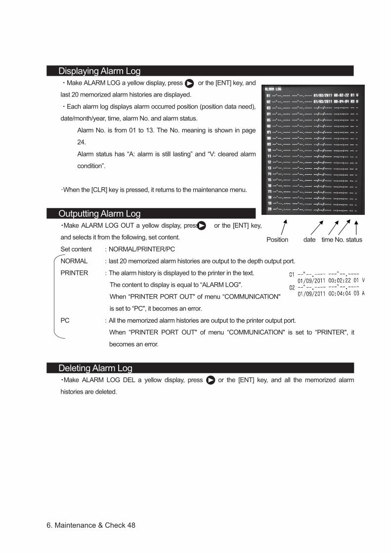
Displaying Alarm Log Make ALARM LOG a yellow display, press or the [ENT] key, and
last 20 memorized alarm histories are displayed.
Each alarm log displays alarm occurred position (position data need),
date/month/year, time, alarm No. and alarm status.
Alarm No. is from 01 to 13. The No. meaning is shown in page
24.
Alarm status has “A: alarm is still lasting” and “V: cleared alarm
condition”.
When the [CLR] key is pressed, it returns to the maintenance menu.
Outputting Alarm Log Make ALARM LOG OUT a yellow display, press or the [ENT] key,
and selects it from the following, set content.
Set content NORMAL/PRINTER/PC
NORMAL last 20 memorized alarm histories are output to the depth output port.
PRINTER The alarm history is displayed to the printer in the text.
The content to display is equal to “ALARM LOG".
When “PRINTER PORT OUT" of menu “COMMUNICATION"
is set to “PC", it becomes an error.
PC All the memorized alarm histories are output to the printer output port.
When “PRINTER PORT OUT" of menu “COMMUNICATION" is set to “PRINTER", it
becomes an error.
Deleting Alarm Log Make ALARM LOG DEL a yellow display, press or the [ENT] key, and all the memorized alarm
histories are deleted.
Position date time No. status

6. Maintenance & Check 49
Executing Line Monitor Make LINE MONITOR a yellow display, press or the [ENT] key, and the following menu is displayed.
LINE MONITOR NAV/DEPTH ALR PRINTER
Make the monitor item a yellow display, press or the [ENT] key, and the input/output data of the serial
port is displayed, and input data is displayed in the upper part of the screen, and output data is displayed
under the screen.
When the [CLR] key is pressed, it returns to the maintenance menu.
Displaying RX Monitor Make RX MONITOR a yellow display, press or the [ENT] key, and a present situation of the receiver is
displayed.
LEVEL Detection level of sea bottom (maximum value within the range from sea bottom detection
position to the lower side)
RANGE Range of sea bottom tracking
GAIN Gain setting value
When the [CLR] key is pressed, it returns to the maintenance menu.
Displaying System No. Make SYSTEM No. a yellow display, press or the [ENT] key, and the program version is displayed.
Date
Ver. Version
When the [CLR] key is pressed, it returns to the maintenance menu.
NAV/DEPTH Navigation data/Depth output
ALR ALR Input/Output
PRINTER Printer port

6. Maintenance & Check 50
6.3 Replacing Printer Paper
Do not cut your hand in the blade tip of the paper cutter.
Name Model type Remarks
Printer paper H-7ZPJD0384 TF50KS-E2D for build-in printer H-6ZCAF00252A for optional DPU-414 printer
After turning off the power supply of this equipment, exchange papers.
When the printer cover is opened while turning on, the alarm of “NO PAPER" sounds.
Open the paper cover by pressing the paper cover opening button.
Set the paper like the direction of figure.
Shut the cover after making the paper tip put out outside of the printer and pushing both ends of the
upper paper cover.
A red mark of a paper slip previous notice puts out from 1m remain when the remainder of the paper
decreases.

6. Maintenance & Check 51
6.4 Replacing Backup BatteryBackup battery is use for backup the menu set up item. Battery life depends on the leave time of OFF
status. About 5 years are the battery lifetime.
If the backup battery is low, “Please do connection setting of transducers.” Message will pop up with
turning on. See page 37, 4.8 Master Reset.
If your JFE-680 becomes like this, please contact our agent to order replacing the battery.
Backup lithium coin cell battery CR2032 Note : For the safety, turn off the main power switch of echo sounder. Then start to replace the battery.
The setting data would be kept about twenty minutes by super capacitor. So, if you finish replacing the
battery in these minutes, the setting data would not need to set again.
Outline of battery replace 1 Turn off the echo sounder. Turn off the circuit breaker. Work after waiting for about 10 seconds. 2 Remove the front cover of the echo sounder. 3 Replace the battery. 4 Set the front cover of the echo sounder. 5 Turn on the circuit breaker. Turn on the echo sounder.
1 Press PWR/PANEL and BRILL for about three seconds to turn off the echo sounder. Turn off the circuit breaker. Work after waiting for about 10 seconds.
2 Remove the front cover of the echo sounder. Remove 4 screws on the front cover. The battery is installed back side of the LCD.
Backup battery

6. Maintenance & Check 52
3 Replace the battery.
Stick the small width (narrower than 5mm) slotted screwdriver between the battery and the battery socket.
Lift the screwdriver to take off the battery.
Set the new battery in the battery socket. The positive (+) terminal is upside.
Push the battery until stayed in horizontally.
6. Maintenance & Check 53
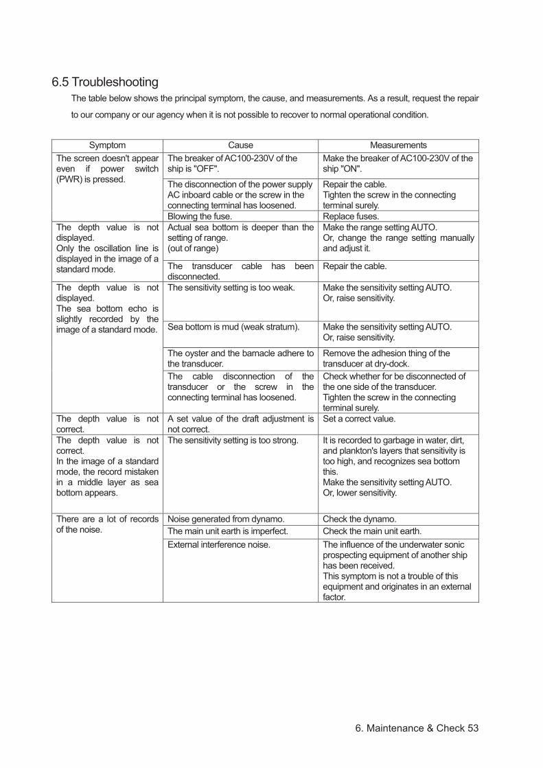
6.5 TroubleshootingThe table below shows the principal symptom, the cause, and measurements. As a result, request the repair
to our company or our agency when it is not possible to recover to normal operational condition.
Symptom Cause Measurements The screen doesn't appear even if power switch (PWR) is pressed.
The breaker of AC100-230V of the ship is "OFF".
Make the breaker of AC100-230V of the ship "ON".
The disconnection of the power supply AC inboard cable or the screw in the connecting terminal has loosened.
Repair the cable. Tighten the screw in the connecting terminal surely.
Blowing the fuse. Replace fuses. The depth value is not displayed. Only the oscillation line is displayed in the image of a standard mode.
Actual sea bottom is deeper than the setting of range. (out of range)
Make the range setting AUTO. Or, change the range setting manually and adjust it.
The transducer cable has been disconnected.
Repair the cable.
The depth value is not displayed. The sea bottom echo is slightly recorded by the image of a standard mode.
The sensitivity setting is too weak. Make the sensitivity setting AUTO. Or, raise sensitivity.
Sea bottom is mud (weak stratum). Make the sensitivity setting AUTO. Or, raise sensitivity.
The oyster and the barnacle adhere to the transducer.
Remove the adhesion thing of the transducer at dry-dock.
The cable disconnection of the transducer or the screw in the connecting terminal has loosened.
Check whether for be disconnected of the one side of the transducer. Tighten the screw in the connecting terminal surely.
The depth value is not correct.
A set value of the draft adjustment is not correct.
Set a correct value.
The depth value is not correct. In the image of a standard mode, the record mistaken in a middle layer as sea bottom appears.
The sensitivity setting is too strong. It is recorded to garbage in water, dirt, and plankton's layers that sensitivity is too high, and recognizes sea bottom this. Make the sensitivity setting AUTO. Or, lower sensitivity.
There are a lot of records of the noise.
Noise generated from dynamo. Check the dynamo. The main unit earth is imperfect. Check the main unit earth. External interference noise. The influence of the underwater sonic
prospecting equipment of another ship has been received. This symptom is not a trouble of this equipment and originates in an external factor.
6. Maintenance & Check 54
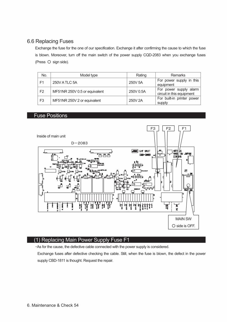
6.6 Replacing Fuses Exchange the fuse for the one of our specification. Exchange it after confirming the cause to which the fuse
is blown. Moreover, turn off the main switch of the power supply CQD-2083 when you exchange fuses
(Press sign side).
No. Model type Rating Remarks
F1 250V A TLC 5A 250V 5A For power supply in this equipment
F2 MF51NR 250V 0.5 or equivalent 250V 0.5A For power supply alarm circuit in this equipment
F3 MF51NR 250V 2 or equivalent 250V 2A For built-in printer power supply
Fuse Positions
Inside of main unit
(1) Replacing Main Power Supply Fuse F1 As for the cause, the defective cable connected with the power supply is considered.
Exchange fuses after defective checking the cable. Still, when the fuse is blown, the defect in the power
supply CBD-1811 is thought. Request the repair.
MAIN SW
side is OFF.

6. Maintenance & Check 55
(2) Replacing 24VDC Input Power Fail Alarm Fuse F2 As for the cause, the abnormal voltage input is thought.
Confirm the input voltage of interface unit J11 terminal stand .
Exchange fuses after confirming it is rating DC24V(DC21.5 31.5V).
Still, when the fuse is blown, because defects of the interface unit CQD-2083, the power supply CBD-1811,
the operation unit CCK-963, and wiring CFQ-9139, CFQ-9140, CFQ-9148, etc. are thought. Request the
repair.
(3) Replacing Built-in Printer Fuse F3 As for the cause, in the case of the built-in printer, the over current of the external unit connected with printer
or Interface unit J13 is thought.
Remove the connecting cable of the external unit once. Still, when the fuse is blown, because defects of an
interface unit CQD-2083, a built-in printer H-7HPJD0001, and wiring CQD-9142, etc. are thought. Request
the repair.
6.7 Repair Parts
Parts name Type Remarks Main Unit CDJ-2338-2A TX/RX Unit CMN-720-22 200kHz/200kHz as standard
CMN-720B25 CMN-720-25
200kHz/50kHz-A as option 200kHz/50kHz as option(Discontinued)
CMN-720B55 CMN-720-55
50kHz-A/50kHz-A as option 50kHz/50kHz as option(Discontinued)
Power Supply Unit CBD-1811 I/F Unit CQD-2083 Operation Unit CCK-963 LCD Panel ASSY CCN-415 Printer H-7HPJD0001 Screen plate for JFE-680 printer BRBX05341 Closing board when there is no printer
Screw Cap BRBX05352 Decoration cap of front four corners screw

7. Consider Installation • Do not install the JFE-680 where subject to the following conditions as such conditions may
cause failures and reduce the life of the equipment.
1. Where liable to be splashed with water.
2. Where ventilation is poor.
• Do not coat the part of the transducer that outputs the ultrasonic waves (the rubber part of the tank on the ship's bottom) with the hull coating as this will deteriorate performance.
7. Consider Installation 56
8. After-sales Service
8.1 When Requesting Servicing If you suspect a fault, stop using the equipment and contact JRC or its agent.
Servicing Under Warranty When the fault develops while the equipment is being used as indicated in the Instruction Manual, the equipment will be repaired free of charge. However, if the fault occurs as the result of misuse, negligence, natural disaster, fire, or other acts of God, a charge will be made for its repair.
Servicing Out of Warranty If the fault can be rectified by servicing the equipment, the repair will be made at your expense.
Details to be Submitted - Name, type No., month and year of manufacture, and serial number; - Nature of fault (in as much detail as possible); - Contact details (your name, address and phone number, etc.)
8.2 Recommendations for Inspection and Maintenance Depending on the conditions of usage, the performance may deteriorate due to the aging of components. In such conditions, please consult JRC or its agent for inspection and maintenance, as distinct from the daily care you normally give your equipment. Note that such inspection and maintenance is subject to charge. Please consult JRC or its agent for further details of any part of the afterservice conditions. Contact: See list at end of manual.
8. After-sales Service 57

8.3 Warranty & After-sales Service
For further details of after-sale service, contact the JRC Offices.
Warranty Period For one year after following installation. Warranty period is subject to change by contract.
Keeping period of maintenance partsKeeping period of maintenance parts is ten years from the production is discontinued.
Repair within the Warranty Period If any failure occurs in the product during its normal operation in accordance with the instruction manual, the dealer or JRC will repair free of charge. In case that any failure is caused due to misuse, faulty operation, negligence or force major such as natural disaster and fire, the product will be repaired with charges.
Repair after the Warranty PeriodIf any defective function of the product is recoverable by repair, the repair of it will be made at your own charge upon your request. But if more than ten years has passed after the discontinuation of production and no maintenance parts, JRC cannot repair.
8. After-sales Service 58

9. Disposal
9.1 Disposal of this equipment If this equipment is to be disposed, please follow the guidelines of the local body governing the location at which the equipment is disposed of.
9. Disposal 59
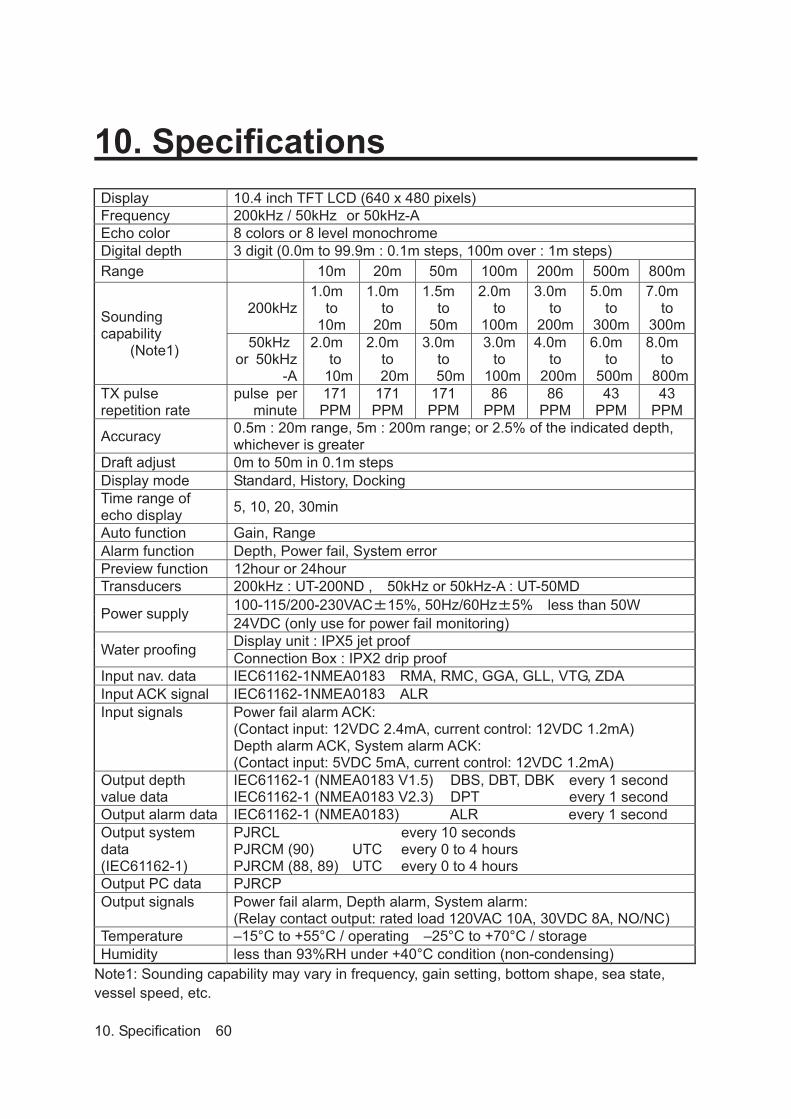
10. Specifications Display 10.4 inch TFT LCD (640 x 480 pixels) Frequency 200kHz / 50kHz or 50kHz-A Echo color 8 colors or 8 level monochrome Digital depth 3 digit (0.0m to 99.9m : 0.1m steps, 100m over : 1m steps) Range 10m 20m 50m 100m 200m 500m 800m
Soundingcapability
(Note1)
200kHz1.0m
to10m
1.0mto
20m
1.5mto
50m
2.0mto
100m
3.0mto
200m
5.0mto
300m
7.0mto
300m50kHz
or 50kHz-A
2.0mto
10m
2.0mto20m
3.0mto50m
3.0mto
100m
4.0mto
200m
6.0mto
500m
8.0mto
800mTX pulse repetition rate
pulse per minute
171PPM
171PPM
171PPM
86PPM
86PPM
43PPM
43PPM
Accuracy 0.5m : 20m range, 5m : 200m range; or 2.5% of the indicated depth, whichever is greater
Draft adjust 0m to 50m in 0.1m steps Display mode Standard, History, Docking Time range of echo display 5, 10, 20, 30min
Auto function Gain, Range Alarm function Depth, Power fail, System error Preview function 12hour or 24hour Transducers 200kHz : UT-200ND , 50kHz or 50kHz-A : UT-50MD
Power supply 100-115/200-230VAC 15%, 50Hz/60Hz 5% less than 50W 24VDC (only use for power fail monitoring)
Water proofing Display unit : IPX5 jet proof Connection Box : IPX2 drip proof
Input nav. data IEC61162-1NMEA0183 RMA, RMC, GGA, GLL, VTG, ZDA Input ACK signal IEC61162-1NMEA0183 ALR Input signals Power fail alarm ACK:
(Contact input: 12VDC 2.4mA, current control: 12VDC 1.2mA) Depth alarm ACK, System alarm ACK: (Contact input: 5VDC 5mA, current control: 12VDC 1.2mA)
Output depth value data
IEC61162-1 (NMEA0183 V1.5)IEC61162-1 (NMEA0183 V2.3)
DBS, DBT, DBKDPT
every 1 second every 1 second
Output alarm data IEC61162-1 (NMEA0183) ALR every 1 second Output system data (IEC61162-1)
PJRCL PJRCM (90) PJRCM (88, 89)
UTCUTC
every 10 seconds every 0 to 4 hours every 0 to 4 hours
Output PC data PJRCP Output signals Power fail alarm, Depth alarm, System alarm:
(Relay contact output: rated load 120VAC 10A, 30VDC 8A, NO/NC) Temperature –15°C to +55°C / operating –25°C to +70°C / storage Humidity less than 93%RH under +40°C condition (non-condensing)
Note1: Sounding capability may vary in frequency, gain setting, bottom shape, sea state, vessel speed, etc.
10. Specification 60

Appendix Noise
Bubble Noise Bubble Interruption
Interference Noise from other ship
Plankton layer
Appendix 61

Actual Pictures
Zero line Seabed
DISP TRANS DISP SURF
DISP KEEL
figure A
Seabed
Zero line Third reflection of bottom
Second reflection of bottom Seabed
In case of a shallow seabed or when increasing the amplifier sensitivity, two seabed lines may be recorded. This results from a multi-reflection of ultra-sonic wave between the seabed and hull bottom or surface of sea, in such manner: An emitted ultrasonic wave once reflected at the seabed returns toward the transducer or surface or sea but reflected at the hull bottom or surface of sea and again reflected at the seabed toward the transducer. Such multiple recording of the seabed may appear due to change of bottom quality. A double or triple reflection may be sometimes recorded. In any case, a first reflection recording from the zero line represents a real seabed return. A first, second and third reflection lines of seabed arrange with approximately equal spacing on the recording. In addition, the shade of the reflection lines fades little by little away from the fast line on the recording. From these conditions, they can be easily identified as a multi reflection.
Appendix 62

Seabed Quality Change
Mud Rock
In case of a hard seabed composed of rocks etc., its return trails long, as shown in right chart. In case of a soft seabed made of mud, seaweed, etc., they poorly reflect an ultrasonic wave to result in thin recording of the seabed with short trail. The seabed quality can be more sufficiently identified with use of wider beam angle and longer pulse width. Usually lower frequency is used.
Appendix 63

Abrupt-Sloped Seabed
Sidelobe
False echo
A dim echo may sometimes appear along an abrupt slope of seabed, as if it were floating above the slope, when recording. In case of flat seabed, thin second return of seabed may sometimes appear, which is slightly below the actual seabed. In either case, the dim or thin echoes are false and produced by side lobes of ultrasonic beam from the transducer. Any false echo is thinner than and parallel to a real echo.
Appendix 64

The echo of a seabed with abrupt slope is recorded as a lone difficult to see and less discriminative, since it tends to accompany with a false echo due to the side lobe and the inherent property of directivity. In particular, a seabed with abrupt slope and heavily rugged surface provided an echo very difficult to display on the recording.
Appendix 65

7ZPNB0043
(Type): JFE-680 (Name): Echo Sounder
(Pb) (Hg) (Cd) (Cr6+) (PBB) (PBDE)
(Recorder Unit)
(Hull-Bottom Unit)
(Peripherals) (Options) (Printer) (Cables) (Documents)
JRC Code No. : 7ZPNA2012A
Management Methods on Control of Pollution from Electronics Information Products of the People's Republic of China
Indicates that this toxic, or hazardous substance contained in all of the homogeneous materials for this part is below the requirement in SJ/T11363-2006.)
SJ/T11363-2006 (Indicates that this toxic or hazardous substance contained in at least one of the homogeneous materials used for this part is above the limit requirement in SJ/T 11363-2006.)
(Part name)(Toxic and Hazardous Substances and Elements)
Declaration on toxic & hazardous substances or elementsof Electronic Information Products
(Names & Content of toxic and hazardous substances or elements
Japan Radio Company Limited
1

01ETM ISO 9001, ISO 14001 Certified
Printed in Japan
Marine Service [email protected]
Telephone :Facsimile :e-mail :
AMSTERDAM BranchTelephone :Facsimile :e-mail :
SEATTLE BranchTelephone :Facsimile :e-mail :
CODE No.7ZPNA2012FCODE No.7ZPNA2012F
DEC. 2012 Edition 6 JRCDEC. 2012 Edition 6 JRC
Not use the asbestos
For further information,contact:
URL http://www.jrc.co.jp
INSTRUCTIONINSTRUCTIONMANUALMANUAL
Echo SounderEcho SounderJFE-680JFE-680