Embed Size (px)
Citation preview

IM-TE91A920-EN2 ESE02460EN Date of issue: Apr. 11, 2014 First published: Nov. 15, 2013
Instruction Manual, Alfa Laval Hybrid Powder Mixer HPM-M15 & HPM-S15 With
• Standard
Original manual
www.sks-online.com www.sks-webshop.com

www.sks-online.com www.sks-webshop.com
The designated company Alfa Laval Kolding A/S Company name Albuen 31, 6000 Kolding, Denmark Address +45 79 32 20 00 Phone no.
hereby declare that
Hybrid Powder Mixer AL-HPM-M15 & AL-HPM-S15 Denomination Type
is in conformity with the following regulations and directives with amendments:
- Machinery Directive 2006/42/EC - Regulation (EC) No. 1935/2004 and Regulation (EC) No. 10/2011 - Low Voltage Directive (LVD) 2006/96/EF Directive 2006/95/EC on low voltage - EMC Directive 2004/108/EF - ROHS Directive 2002/95/EEC
The technical construction file is retained at the above address.
R&D Manager Henrik Falster Hansen Title Name Signature
April 7, 2014 Alfa Laval Kolding A/S
Date Company
www.sks-online.com www.sks-webshop.com

www.sks-online.com www.sks-webshop.com
Contents
Product programme ................................................................................................................................. 4 Standard ............................................................................................................................................................... 4
For your safety ......................................................................................................................................... 5 General hazards ................................................................................................................................................... 5 Intended use of the machine ................................................................................................................................. 5 Protective measures ............................................................................................................................................. 5
Specific safety instructions and the symbols used .................................................................................. 6 General safety instructions .................................................................................................................................... 7 Basic safety measures during normal operation ................................................................................................... 7 Basic safety measures during maintenance, repair and cleaning ......................................................................... 9 Working on the electrical equipment ................................................................................................................... 11 Working on the flush tank.................................................................................................................................... 11 Observe the environmental protection instructions ............................................................................................. 12 Residual risks ...................................................................................................................................................... 12
Function description ............................................................................................................................... 13 Construction of the AL HPM ................................................................................................................................ 13
Setting up and installation ...................................................................................................................... 17 Unpacking and setting up.................................................................................................................................... 17 Connecting the product pipes ............................................................................................................................. 17 Flush tank and axial face seal ............................................................................................................................. 17 Power supply ...................................................................................................................................................... 18
Commissioning ....................................................................................................................................... 19 Connecting the AL HPM to a mixing tank ........................................................................................................... 19 Brief test .............................................................................................................................................................. 20 Information on working with products .................................................................................................................. 20 Powering up the machine.................................................................................................................................... 21
Cleaning and maintenance .................................................................................................................... 22 Cleaning (CIP) .................................................................................................................................................... 22 The axial face seal .............................................................................................................................................. 22 C-Ball Valve ........................................................................................................................................................ 22 Rotor/Stator ......................................................................................................................................................... 22 Barrier fluid installation ........................................................................................................................................ 23 Drive ................................................................................................................................................................... 23
Installation and removal ......................................................................................................................... 24 Rotor/Stator ......................................................................................................................................................... 24 Installing the drive ............................................................................................................................................... 24
Technical data ........................................................................................................................................ 25 Operational data ..................................................................................................................................... 27
Technical data ..................................................................................................................................................... 27 Dimensions/weight .............................................................................................................................................. 27
Parts and spares list ............................................................................................................................... 29 Parts list, Powder Mixer complete, HPM-M15 ..................................................................................................... 29 *) Optional, not part of machineParts drawing, Powder Mixer complete, HPM-M15 ........................................... 29 Parts list, Powder Mixer complete, HPM-S15 ..................................................................................................... 31 Parts drawing, Powder Mixer complete, HPM-S15 ............................................................................................. 32
www.sks-online.com www.sks-webshop.com

Parts list, Base frame, HPM-M15 ........................................................................................................................ 33 Parts drawing, Base frame, HPM-M15 ................................................................................................................ 34 Parts list, Flush container, HPM-M15/HPM-S15 ................................................................................................. 35 Parts drawing, Flush container, HPM-M15/HPM-S15 ......................................................................................... 35 Parts list, C-ball valve, HPM-M15/HPM-S15 ....................................................................................................... 36 Parts drawing, C-ball valve, HPM-M15/HPM-S15 ............................................................................................... 36 Parts list, Inlet tube, HPM-M15/HPM-S15 ........................................................................................................... 37 Parts drawing, Inlet tube ..................................................................................................................................... 37 Parts list, Butterfly valve, HPM-M15 .................................................................................................................... 38 Parts drawing, Butterfly valve, HPM-M15 ............................................................................................................ 38 Parts list, High shear and pump unit, HPM-M15/HPM-S15 ................................................................................. 39 Parts drawing, High shear and pump unit, HPM-M15/HPM-S15 ......................................................................... 40
Additional documents ............................................................................................................................. 41 General Information ................................................................................................................................ 42
Service / Repair ................................................................................................................................................... 42 Warranty.............................................................................................................................................................. 42 How to contact Alfa Laval .................................................................................................................................... 42
© Alfa Laval Corporate AB This document and its contents is owned by Alfa Laval Corporate AB and protected by laws governing intellectual property and thereto related rights. It is the responsibility of the user of this document to comply with all applicable intellectual property laws. Without limiting any rights related to this document, no part of this document may be copied, reproduced or transmitted in any form or by any means (electronic, mechanical, photocopying, recording, or otherwise), or for any purpose, without the expressed permission of Alfa Laval Corporate AB. Alfa Laval Corporate AB will enforce its rights related to this document to the fullest extent of the law, including the seeking of criminal prosecution.
www.sks-online.com www.sks-webshop.com

www.sks-online.com www.sks-webshop.com

Product programme
This manual covers the product program for Alfa Laval Hybrid Powder Mixer HPM-M15 and HPM-S15.
Standard
HPM-M15
Version Item no. Motor Funnel Inlet Outlet
Frequency converter, for voltage
US TE35A001 NEMA TEFC Wash Down (IP66) 40 l TriClamp TriClamp 3 Phase 380-480 Vac
(±10%) 50-60 Hz
CANADA TE35A002 NEMA TEFC Wash Down (IP66) 40 l TriClamp TriClamp 3 Phase 525-690 Vac
(±10%) (Canada) 50-60 Hz
ROW TE35A000 IEC IP55 + Shroud 40 l DIN DIN 3 Phase 380-480 Vac (±10%) 50-60 Hz
HPM-S15
Version Item no. Motor Funnel Inlet Outlet Motor voltage
US/CAN 9614302801 NEMA TEFC Wash Down (IP66) 40 l TriClamp TriClamp 3 Phase 380-480 Vac
(±10%) 50-60 Hz
ROW 9614302701 IEC IP55 + Shroud 40 l DIN DIN 3 Phase 380-480 Vac (±10%) 50-60 Hz
www.sks-online.com www.sks-webshop.com

For your safety
General hazards
The machine is not dangerous in itself, provided that it is used as intended. To prevent injury to people and damage to the machine, it must only be operated as intended. However, the manufacturer is unable to foresee dangers that may result from installing or combining the machine with other machines. The machine operator must observe the safety instructions when operating the machine. The machine may only be operated by authorised, trained operators. The machine may only be commissioned when fully installed.
Intended use of the machine
The machine is used for wetting and dispersing powder in fluids and also for blending fluids in fluids. The machine is suitable for producing products with viscosities up to 500 mPas, based on the viscosity at the powder mixer impeller in the case of Newtonian products. To protect the mixing tools against damage by foreign objects, e.g. screws, stones, pieces of wood, etc., we recommend the use of suitable measures to prevent such objects from entering the machine. The safety mesh provided is one such measure and should be used at all times. Place the safety mesh in the funnel before introducing the powder.
Protective measures
Operator’s duty of care
The machine (including the sub-assemblies) has been designed and built taking into account a risk analysis and after careful selection of harmonised standards and other technical specifications to be observed. It therefore conforms to the state of the art and provides maximum safety in operation. However, the safety of the machine in practice can only be achieved if all the necessary measures are adopted for this purpose. It is part of the machine operator’s duty of care to plan these measures and monitor their implementation. In particular, the operator must make sure that • the machine is only used as intended;
• the machine is only operated if it is in perfect working order and, in particular, the functioning of the safety devices is checked regularly;
• the necessary personal protection for operating, maintenance and repair personnel is both available and worn;
• the operating instructions are always legible and complete versions are available at the place where the machine is installed;
• only duly qualified and authorised personnel operates, maintains and repairs and the machine;
• this personnel is instructed regularly in all relevant issues relating to health and safety in the workplace and protection of the environment and is also familiar with the operating instructions and the safety information contained in those instructions;
• safety and warning information on the machine is not removed and it is legible.
www.sks-online.com www.sks-webshop.com

Specific safety instructions and the symbols used
The following operating instructions include specific safety information that refers to unavoidable residual risks when operating and maintaining the machine. The residual risks include risks for:
• people • product and machine • the environment.
The symbols used in the operating instructions must draw attention to the safety instructions in particular.
Warning This symbol means that personal danger in particular is to be expected. (danger to life, risk of injury).
Danger!
Warning This symbol means that danger is to be expected in particular for machine, material and the environment.
Caution!
Note: This symbol is not a safety instruction, but provides information to allow a better understanding of the machine operations.
www.sks-online.com www.sks-webshop.com

General safety instructions
Warning Changes may only be made to the installation or parts of it subject to the written consent of ALFA LAVAL, otherwise, the warranty and declaration of conformity will lapse.
Warning The machine is live when the power supply is connected. This voltage can have life-endangering effects on contact. We reserve the right to make technical changes.
Basic safety measures during normal operation
Warning Before switching on the machine, make sure you know what to do in the event of an incident.
Warning The machine may only be operated by qualified, authorised personnel, who are familiar with the operating instructions (including those for the sub-assemblies) and are able to work accordingly!
Warning Replace all hoses regularly as a preventive maintenance measure, even if not obviously damaged). (Observe the manufacturers’ information)
Warning If components of the installation are temperature-controlled, there is a risk that parts not insulated and supply lines may catch fire above a temperature of 65°C. In this case, the operator must protect the hot parts against contact.
Warning If water is used as a barrier medium, it must be cooled at temperatures above 85°C, otherwise, the seal may be damaged.
www.sks-online.com www.sks-webshop.com
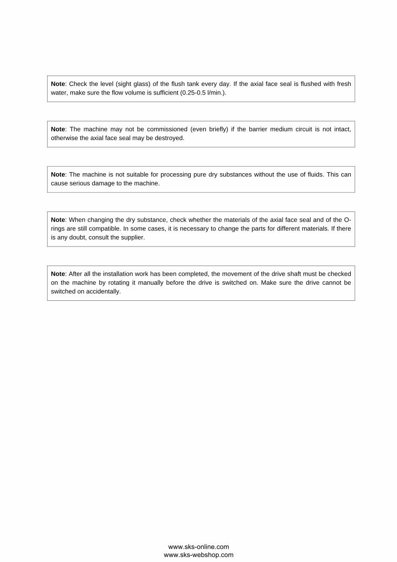
Note: Check the level (sight glass) of the flush tank every day. If the axial face seal is flushed with fresh water, make sure the flow volume is sufficient (0.25-0.5 l/min.).
Note: The machine may not be commissioned (even briefly) if the barrier medium circuit is not intact, otherwise the axial face seal may be destroyed.
Note: The machine is not suitable for processing pure dry substances without the use of fluids. This can cause serious damage to the machine.
Note: When changing the dry substance, check whether the materials of the axial face seal and of the O-rings are still compatible. In some cases, it is necessary to change the parts for different materials. If there is any doubt, consult the supplier.
Note: After all the installation work has been completed, the movement of the drive shaft must be checked on the machine by rotating it manually before the drive is switched on. Make sure the drive cannot be switched on accidentally.
www.sks-online.com www.sks-webshop.com
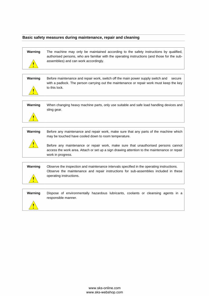
Basic safety measures during maintenance, repair and cleaning
Warning The machine may only be maintained according to the safety instructions by qualified, authorised persons, who are familiar with the operating instructions (and those for the sub-assemblies) and can work accordingly.
Warning Before maintenance and repair work, switch off the main power supply switch and secure with a padlock. The person carrying out the maintenance or repair work must keep the key to this lock.
Warning When changing heavy machine parts, only use suitable and safe load handling devices and sling gear.
Warning Before any maintenance and repair work, make sure that any parts of the machine which may be touched have cooled down to room temperature. Before any maintenance or repair work, make sure that unauthorised persons cannot access the work area. Attach or set up a sign drawing attention to the maintenance or repair work in progress.
Warning Observe the inspection and maintenance intervals specified in the operating instructions. Observe the maintenance and repair instructions for sub-assemblies included in these operating instructions.
Warning Dispose of environmentally hazardous lubricants, coolants or cleansing agents in a responsible manner.
www.sks-online.com www.sks-webshop.com

Note: After all the installation work has been completed, the movement of the drive shaft must be checked on the machine by rotating it manually before the drive is switched on. Make sure the drive cannot be switched on accidentally.
Note: The rotor shaft nut must be tightened by hand and then with a torque wrench (tightening torque approximately 30 Nm). It is also advisable to lock the thread with a liquid thread lock, such as Loctite, for example.
Note: Any work on the axial face seal must be done very carefully. The seals consist of a brittle material and are therefore sensitive to shocks. Avoid impact.
Warning The cleaning (CIP) of the powder mixer is carried out in combination with the cleaning of the tank or when cleaning the pipe system of the entire installation. The funnel and the ball valve must be removed and replaced by the blind flange supplied. This guarantees that no CIP fluid, such as soda lye or acid, for example, will leak out if the ball valve is opened accidentally.
www.sks-online.com www.sks-webshop.com
Working on the electrical equipment
Note: Switch on briefly to check whether the motor is rotating in the direction indicated (arrow on the pump housing).
Note: The machine connection must comply with VDE standards.
When the motor is connected to the power supply, check that the motor voltage, frequency converter and mains voltage correspond.
The voltages are indicated on the motor rating plate or the frequency converter data sheet.
Warning Only qualified electricians may repair the machine’s electrical equipment. Check the electrical equipment regularly. Re-tighten any loose connections. Replace damaged lines/cables immediately. Keep the frequency converter locked and clean at all times! Only authorised persons with key/tool are allowed access. Never hose down a frequency converter to clean it.
Working on the flush tank
Warning The machine must not be commissioned (even briefly) if the barrier medium circuit is not intact, otherwise the axial face seal may be destroyed. Check that screw connections are firmly tightened after any maintenance or repair work. After completion of the maintenance or repair work, and before resuming production, make sure that all the materials, tools and other equipment required for carrying out the maintenance or repair work are removed from the work area of the installation and that all the installation’s safety devices are functioning properly.
www.sks-online.com www.sks-webshop.com

Observe the environmental protection instructions
Warning The legal obligations relating to the prevention of waste and recycling/disposal must be observed whenever work is done on and with the machine. Particularly when installation, repair and maintenance work is performed, water-hazardous substances, such as:
• lubricating grease and oil • hydraulic fluids • coolants • solvent-containing cleaning fluids
do not contaminate the soil or enter the drains.
These substances must be stored, transported, collected and disposed of in suitable tanks.
Residual risks
The machine has been designed so that the machine itself and its accessories cannot cause any risks for people, products and the environment. The operating instructions have been written so that no risks arise when observing warning signs and maintenance specifications. However, it cannot be ruled out that risks may occur as the result of human error. No further risks are to be expected if the equipment is used correctly and the recommendations and instructions according to the accident prevention regulations (UVV) and the occupational insurance associations are observed.
www.sks-online.com www.sks-webshop.com

Function description
The Alfa Laval Hybrid Powder Mixer (AL HPM) is a combination of two technologies (powder mixer and pump) and is mainly used to disperse solids (power or crystals) in fluids. Because of the high pressure that the HPM can generate, even during powder intake (up to 4 bar), it can also be used as a mobile feed or discharge pump or as a CIP pump. The powder to be mixed is delivered to the HPM via the funnel (item 1 in Figure 1) and homogenised or dispersed in the fluid flow with the aid of a rotor-stator system in the first stage (item 2 in Figure 1). In the second stage, the mixture is then discharged from the equipment with the aid of the impeller (item 3 in Figure 1). During this process, a product sub-flow is recirculated via a second (smaller) connection (item 4 in Figure 1). This sub-flow is introduced into the injector (item 5 in Figure 1). This generates a negative pressure at the funnel outlet, which in turn allows the powder to be drawn in. NOTE: The function is the same on the stationary HPM-S15 version shown on figure 2.
Flow
Pos.1
Pos.3
Pos.2
Outlet
Pos.4 circulation Pos.5 Injector
Inlet
Figure 1
Figure 2
www.sks-online.com www.sks-webshop.com

Construction of the AL HPM
The equipment consists of the following units:
• frequency converter (Only HPM-M15) • drive • axial face seal • injector • rotor/stator, stage 1 • pump impeller, stage 2 • sight glass (Only HPM-M15) • funnel and top plate (Top plate only HPM-M15) • Frame with wheels (Only HPM-M15)
Figure 3, HPM-M15
Figure 4, HPM-S15
www.sks-online.com www.sks-webshop.com
Frequency converter (Only on HPM-M15)
The frequency converter used is the Danfoss FC 300. Details of the frequency converter are given in the separate operating instructions from Danfoss.
Drive
The power is transmitted from the electric motor to the drive shaft via a three-phase motor. Details of the drive are included in the separate operating instructions for the multi-stage centrifugal pump LKH-112. Axial face seal
Details of the axial face seal are included in the separate operating instructions for the multi-stage centrifugal pump LKH-112. Injector
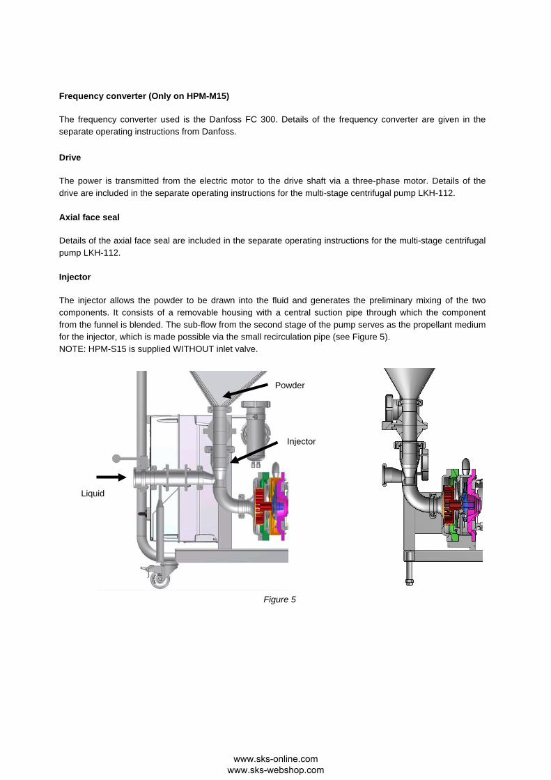
The injector allows the powder to be drawn into the fluid and generates the preliminary mixing of the two components. It consists of a removable housing with a central suction pipe through which the component from the funnel is blended. The sub-flow from the second stage of the pump serves as the propellant medium for the injector, which is made possible via the small recirculation pipe (see Figure 5). NOTE: HPM-S15 is supplied WITHOUT inlet valve.
Injector
Powder
Liquid
Figure 5
www.sks-online.com www.sks-webshop.com
Rotor/stator, stage 1
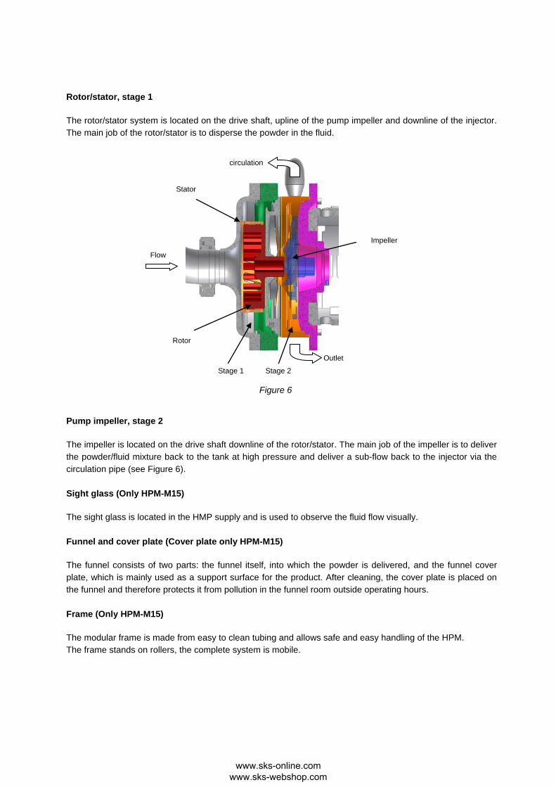
The rotor/stator system is located on the drive shaft, upline of the pump impeller and downline of the injector. The main job of the rotor/stator is to disperse the powder in the fluid.
Pump impeller, stage 2
The impeller is located on the drive shaft downline of the rotor/stator. The main job of the impeller is to deliver the powder/fluid mixture back to the tank at high pressure and deliver a sub-flow back to the injector via the circulation pipe (see Figure 6). Sight glass (Only HPM-M15)
The sight glass is located in the HMP supply and is used to observe the fluid flow visually. Funnel and cover plate (Cover plate only HPM-M15)
The funnel consists of two parts: the funnel itself, into which the powder is delivered, and the funnel cover plate, which is mainly used as a support surface for the product. After cleaning, the cover plate is placed on the funnel and therefore protects it from pollution in the funnel room outside operating hours. Frame (Only HPM-M15)
The modular frame is made from easy to clean tubing and allows safe and easy handling of the HPM. The frame stands on rollers, the complete system is mobile.
Flow
circulation
Stator
Rotor
Stage 1 Stage 2
Impeller
Outlet
Figure 6
www.sks-online.com www.sks-webshop.com

Setting up and installation
Unpacking and setting up
When unpacking, check all parts for damage in transit. Damaged parts must not be used. In the event of any damage, notify the transport company and relevant transport insurance company immediately. A suitably qualified member of staff must unpack, clean and assemble the machine in accordance with the installation instructions. Goods must be stored and transported in the original packing. Avoid any loading or mechanical stress, in particular of housings, shafts, bearing points, through foreign objects or inadmissible vibration. Goods may only be transported on the load handling equipment provided for this purpose. The machine must be set up safely on the floor so that it is easily accessible. The machine must not be exposed to any heat radiation or technical magnetic fields. No stands for people or other heavy objects may be attached to the machine. The machine must not be set up in traffic areas. It must be accessible for maintenance and operation at all times. Install the machine as near to the production tank as possible. Lock the rollers to prevent uncontrolled movement of the machine.
Connecting the product pipes
The product inlet and outlet must be firmly and tightly connected to the tank’s circulation pipe (see Figure 7). Keep the product inlet pipe (intake pipe) as short as possible and do not use a diameter smaller than the connection of the unit. Use bigger diameters for increased viscosity in order to reduce the pressure drop on the suction side.
Flush tank and axial face seal
The flush tank and axial face seal can be operated in two ways:
I. Closed-circuit type with a defined volume of barrier fluid
II. Flushed type, where fresh water flows through the axial face seal and then into the gully (0.25-0.5 L/minute).
www.sks-online.com www.sks-webshop.com

In order to guarantee the necessary circulation of the barrier medium through the axial face seal, the hoses have to be correctly connected to the barrier medium tank. The barrier medium used should have the following characteristics:
• low viscosity (similar to water, approximately 1 mPas) • good lubrication capability • good thermal conductivity • product neutrality
Water with a 5% addition of glycerine or glycol is used as the barrier medium as standard. The barrier fluid should reach the middle of the sight glass. At this level, the fill corresponds to approximately 0.7 litres. It only usually has to be replaced if it becomes polluted. After filling, the circuit and the axial face seal in particular should be vented. To do this, undo the return hose on the flush tank and wait until fluid emerges. Then tighten again.
Power supply
Since no dangerous movements are accessible on the machine, no emergency stop has been provided. The machine connection must comply with VDE standards. When the motor is connected to the power supply, check that the motor voltage, frequency converter and mains voltage correspond. The motor voltage is indicated on the motor rating plate or the frequency converter data sheet. Details of the frequency converter are given in the attached operating instructions for the frequency converter.
www.sks-online.com www.sks-webshop.com
Commissioning
The operator must observe VDE standard 0530 when commissioning the machine. The machine may only be operated by trained, authorised operating personnel. Never commission the machine if it is not fully installed. Before commissioning, remove all dirt and foreign objects from the machine and the connected pipes and tanks. Check that machine rotor and stator are running freely and free from contact.
Connecting the AL HPM to a mixing tank
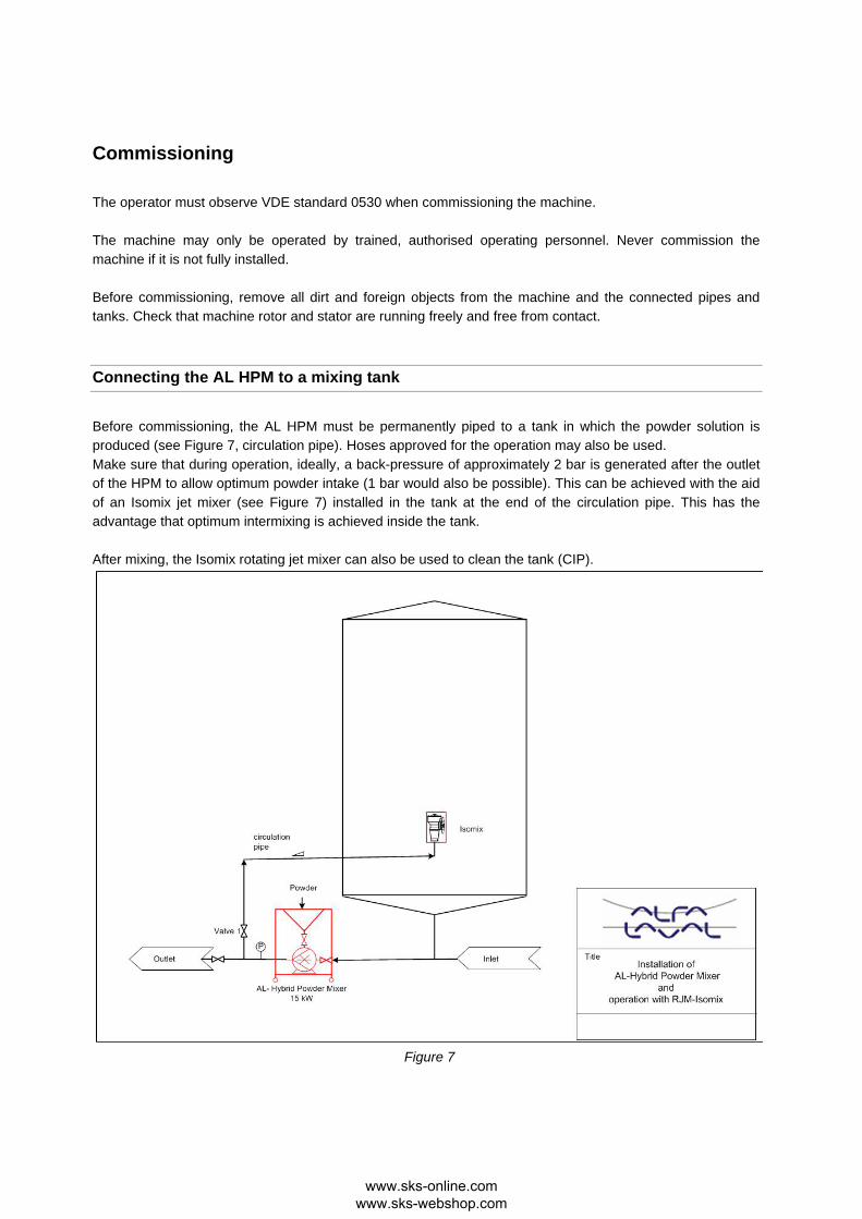
Before commissioning, the AL HPM must be permanently piped to a tank in which the powder solution is produced (see Figure 7, circulation pipe). Hoses approved for the operation may also be used. Make sure that during operation, ideally, a back-pressure of approximately 2 bar is generated after the outlet of the HPM to allow optimum powder intake (1 bar would also be possible). This can be achieved with the aid of an Isomix jet mixer (see Figure 7) installed in the tank at the end of the circulation pipe. This has the advantage that optimum intermixing is achieved inside the tank. After mixing, the Isomix rotating jet mixer can also be used to clean the tank (CIP).
Figure 7
www.sks-online.com www.sks-webshop.com

If there is no Isomix to generate the back-pressure, a simple manual valve (see Figure 7, valve 1), which is connected after the HPM and serves as a throttle, can be used. We recommend that a pressure gauge is always provided after the HPM in order to check the back-pressure generated. We also recommend positioning the HPM inlet at least 200 mm lower than the tank outlet so that the fluid can flow freely into the mixer. The circulation pipe return should be piped so that no air pockets can form in the pipes. The highest point should be the Isomix or the product inlet in the tank (see Figure 7). When connecting permanent pipes, it is also advisable to include a compensator in the pipe in some circumstances. The barrier medium circuit must be filled with a suitable medium before commissioning the machine for the first time (see page 17, Flush tank and axial face seal The machine may not be commissioned (even briefly) if the barrier medium circuit is not intact, otherwise the axial face seal may be destroyed.
Brief test
Check the following again with a short trial run:
1. contamination in the funnel 2. set the valve on the funnel outlet to the closed position 3. the direction of rotation of the motor 4. the fluid level in the flush tank 5. check for any unusual mechanical noises.
Information on working with products
The AL HPM has been designed in particular for mixing solids and fluids. However, the following things also need to be taken into account to work with the machine successfully:
Warning Powders difficult to dissolve or those that swell extensively and have a tendency to stick may only be added in very small quantities, because otherwise the machine may become clogged. Always turn on the ball valve under the funnel slowly and check the intake behaviour at the same time.
Warning Never deposit BIG bags on the modular frame because their weight may damage it.
www.sks-online.com www.sks-webshop.com
Powering up the machine
A minimum fluid volume is required for the machine to function and this has to be introduced into the mixing tank. Please perform the following operations in the order listed when commissioning the machine:
• close the ball valve underneath the funnel.
• open all the valves in the circulation pipe.
• check via the sight glass in the machine inlet whether the fluid is flowing into the machine automatically. If it is, wait until the pipe fills.
• Switch the machine on via the frequency converter and pump the fluid in the circuit.
• With the frequency converter, increase the frequency to 60 Hz (see the frequency converter operating instructions).
• If there is no Isomix mixer in the mixing tank, it must be ensured that a back-pressure of approximately 2 bar is built up by throttling the valve downline of the HPM. Since the valve and the pressure gauge are not part of the supply, the operator has to install these components.
• Insert the safety mesh in the funnel.
• Introduce powder into the funnel.
• Slowly open the ball valve underneath the funnel.
• With hardly soluble powders, the ball valve should only be opened 10%-15%.
• With easily soluble powders, the ball valve may be opened 100%.
• Make sure that during the powder intake, no air pockets form in the powder, as otherwise, air can be entrained into the system. Air pockets should be avoided and any that occur should be dislodged immediately (manually).
• After the powder has been drawn in, close the ball valve immediately and only open it again when powder is next added. Never aspirate air into the system.
• Since the suction power is reduced with increasing viscosity, make sure that the maximum viscosity of 500 cP in the mixer is not exceeded. (500 cP in the case of Newtonian products).
www.sks-online.com www.sks-webshop.com
Cleaning and maintenance
Cleaning (CIP)
The unit has to be cleaned regularly, depending on the type of operation. Dirt in the pipes and chambers can lead to contamination and therefore pollution of the product (when next commissioned). The cleaning (CIP) of the machine is carried out in combination with the cleaning of the tank or when cleaning the pipe system of the entire installation. The funnel and the ball valve, which should be cleaned manually, have to be removed and replaced by the blind flange supplied. This guarantees that no CIP fluid, such as lye or acid can escape if the ball valve is opened accidentally.
The axial face seal
Details of the maintenance of the axial face seal are included in the attached operating instructions for the multi-stage centrifugal pump LKH.
C-Ball Valve
The PTFE housing of the ball valve should be checked regularly. The operator can decide on the checking intervals himself, because it very much depends on the types of powder used.
Rotor/Stator
The high-seed rotor, and also the stator, react sensitively to foreign objects. Therefore, objects such as, for example, screws, stones, welding beads, etc. must be prevented from entering the machine. In the case of highly adhesive and curing media, the machine should also be flushed immediately at the end of the operation. Depending on the abrasiveness of the mixed product, the mixing tools are exposed to a certain amount of wear. Since the size of the shear gap can affect the mixing quality, the tools need to be checked for wear from time to time. The operator can decide on the checking intervals himself, because it very much depends on the types of powder used.
www.sks-online.com www.sks-webshop.com
Barrier fluid installation
Daily fluid level check. Occasional check of the leak-tightness of the hoses, particularly in the area of screw connections.
Drive
Details of the drive are included in the separate operating instructions for the multi-stage centrifugal pump LKH.
Note: Please note that the first step of the pump is modified compared to the standard LKH.
www.sks-online.com www.sks-webshop.com
Installation and removal
After all the installation work has been completed, the movement of the drive shaft must be checked on the machine by rotating it manually before the drive is switched on. Make sure the drive cannot be switched on accidentally. Before any maintenance and repair work, switch off the main power supply switch and lock with a padlock. The person carrying out the maintenance or repair work must hold the key to this lock.
Rotor/Stator
Removal of the Rotor/Stator
1. Isolate the AL HPM from the mains
2. Remove the funnel and cover plate
3. Disconnect supply pipes from solid and fluid pipes.
4. Undo and remove 6 cap nuts from the pump housing
5. Remove the complete pump housing with stator from the machine Fitting the Rotor/Stator
Fit the tools in the reverse order to their removal: To make removal easier, first lightly grease the hubs of the tools with a suitable grease. When fitting, make sure that the O-rings of the individual tools lie correctly in the groove when they are stacked. Firmly tighten the shaft cap nuts with a torque wrench (tightening torque approximately 30 Nm). We also recommend locking the thread with a liquid thread lock, such as Loctite, for example.
Installing the drive
Details for installing the drive are included in the separate operating instructions for the multi-stage centrifugal pump LKH.
www.sks-online.com www.sks-webshop.com
Technical data
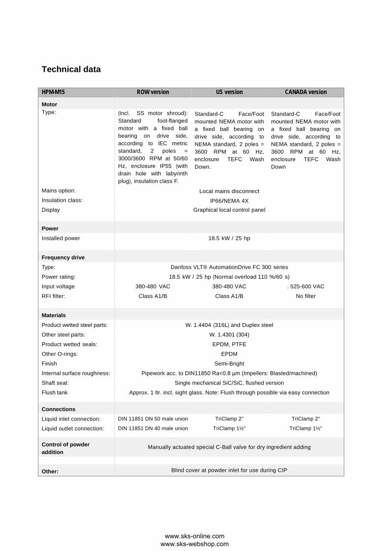
HPM-M15 ROW version US version CANADA version
Motor Type: (Incl. SS motor shroud):
Standard foot-flanged motor with a fixed ball bearing on drive side, according to IEC metric standard, 2 poles = 3000/3600 RPM at 50/60 Hz, enclosure IP55 (with drain hole with labyrinth plug), insulation class F.
Standard-C Face/Foot mounted NEMA motor with a fixed ball bearing on drive side, according to NEMA standard, 2 poles = 3600 RPM at 60 Hz, enclosure TEFC Wash Down.
Standard-C Face/Foot mounted NEMA motor with a fixed ball bearing on drive side, according to NEMA standard, 2 poles = 3600 RPM at 60 Hz, enclosure TEFC Wash Down
Mains option: Local mains disconnect Insulation class: IP66/NEMA 4X Display Graphical local control panel
Power
Installed power 18.5 kW / 25 hp
Frequency drive
Type: Danfoss VLT® AutomationDrive FC 300 series
Power rating: 18.5 kW / 25 hp (Normal overload 110 %/60 s)
Input voltage 380-480 VAC 380-480 VAC . 525-600 VAC
RFI filter: Class A1/B Class A1/B No filter
Materials
Product wetted steel parts: W. 1.4404 (316L) and Duplex steel
Other steel parts: W. 1.4301 (304)
Product wetted seals: EPDM, PTFE
Other O-rings: EPDM
Finish Semi-Bright
Internal surface roughness: Pipework acc. to DIN11850 Ra<0.8 µm (Impellers: Blasted/machined)
Shaft seal: Single mechanical SiC/SiC, flushed version
Flush tank Approx. 1 ltr. incl. sight glass. Note: Flush through possible via easy connection
Connections
Liquid inlet connection: DIN 11851 DN 50 male union TriClamp 2" TriClamp 2"
Liquid outlet connection: DIN 11851 DN 40 male union TriClamp 1½" TriClamp 1½"
Control of powder addition
Manually actuated special C-Ball valve for dry ingredient adding
Other: Blind cover at powder inlet for use during CIP
www.sks-online.com www.sks-webshop.com
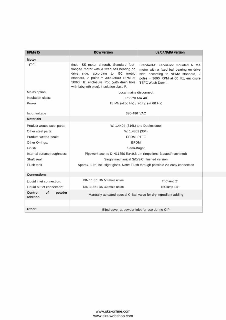
HPM-S15 ROW version US/CANADA version
Motor Type: (Incl. SS motor shroud): Standard foot-
flanged motor with a fixed ball bearing on drive side, according to IEC metric standard, 2 poles = 3000/3600 RPM at 50/60 Hz, enclosure IP55 (with drain hole with labyrinth plug), insulation class F.
Standard-C Face/Foot mounted NEMA motor with a fixed ball bearing on drive side, according to NEMA standard, 2 poles = 3600 RPM at 60 Hz, enclosure TEFC Wash Down.
Mains option: Local mains disconnect Insulation class: IP66/NEMA 4X Power 15 kW (at 50 Hz) / 20 hp (at 60 Hz)
Input voltage 380-480 VAC
Materials
Product wetted steel parts: W. 1.4404 (316L) and Duplex steel
Other steel parts: W. 1.4301 (304)
Product wetted seals: EPDM, PTFE
Other O-rings: EPDM
Finish Semi-Bright
Internal surface roughness: Pipework acc. to DIN11850 Ra<0.8 µm (Impellers: Blasted/machined)
Shaft seal: Single mechanical SiC/SiC, flushed version
Flush tank Approx. 1 ltr. incl. sight glass. Note: Flush through possible via easy connection
Connections
Liquid inlet connection: DIN 11851 DN 50 male union TriClamp 2"
Liquid outlet connection: DIN 11851 DN 40 male union TriClamp 1½"
Control of powder addition
Manually actuated special C-Ball valve for dry ingredient adding
Other: Blind cover at powder inlet for use during CIP
www.sks-online.com www.sks-webshop.com
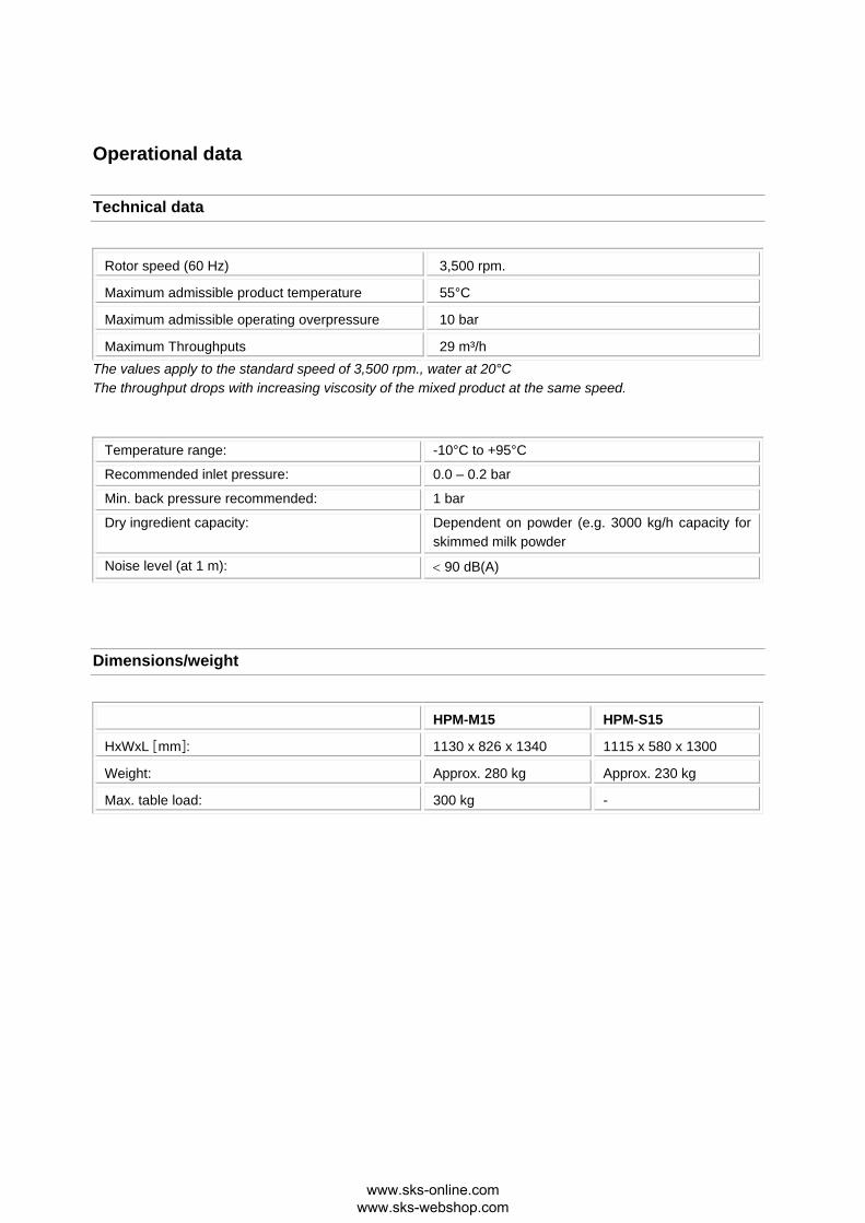
Operational data
Technical data
Rotor speed (60 Hz) 3,500 rpm.
Maximum admissible product temperature 55°C
Maximum admissible operating overpressure 10 bar
Maximum Throughputs 29 m³/h The values apply to the standard speed of 3,500 rpm., water at 20°C The throughput drops with increasing viscosity of the mixed product at the same speed.
Temperature range: -10°C to +95°C
Recommended inlet pressure: 0.0 – 0.2 bar
Min. back pressure recommended: 1 bar
Dry ingredient capacity: Dependent on powder (e.g. 3000 kg/h capacity for skimmed milk powder
Noise level (at 1 m): < 90 dB(A)
Dimensions/weight
HPM-M15 HPM-S15
HxWxL mm: 1130 x 826 x 1340 1115 x 580 x 1300
Weight: Approx. 280 kg Approx. 230 kg
Max. table load: 300 kg -
www.sks-online.com www.sks-webshop.com

- Blank -
www.sks-online.com www.sks-webshop.com
Parts and spares list
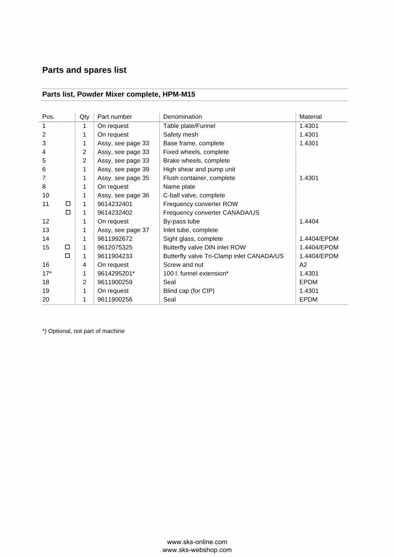
Parts list, Powder Mixer complete, HPM-M15
Pos. Qty Part number Denomination Material 1 1 On request Table plate/Funnel 1.4301 2 1 On request Safety mesh 1.4301 3 1 Assy, see page 33 Base frame, complete 1.4301 4 2 Assy, see page 33 Fixed wheels, complete 5 2 Assy, see page 33 Brake wheels, complete 6 1 Assy, see page 39 High shear and pump unit 7 1 Assy, see page 35 Flush container, complete 1.4301 8 1 On request Name plate 10 1 Assy, see page 36 C-ball valve, complete 11 1 9614232401 Frequency converter ROW 1 9614232402 Frequency converter CANADA/US 12 1 On request By-pass tube 1.4404 13 1 Assy, see page 37 Inlet tube, complete 14 1 9611992672 Sight glass, complete 1.4404/EPDM 15 1 9612075325 Butterfly valve DIN inlet ROW 1.4404/EPDM 1 9611904233 Butterfly valve Tri-Clamp inlet CANADA/US 1.4404/EPDM 16 4 On request Screw and nut A2 17* 1 9614295201* 100 l. funnel extension* 1.4301 18 2 9611900259 Seal EPDM 19 1 On request Blind cap (for CIP) 1.4301 20 1 9611900256 Seal EPDM
*) Optional, not part of machine
www.sks-online.com www.sks-webshop.com

Parts drawing, Powder Mixer complete, HPM-M15
www.sks-online.com www.sks-webshop.com

Parts list, Powder Mixer complete, HPM-S15
Pos. Qty Part number Denomination Material 1 1 Assy, see page 39 High shear and pump unit 2 1 On request By-pass tube 1.4404 3 1 9611900259 Seal EPDM 4 1 Assy, see page 37 Inlet tube, complete 5 1 On request Blind cap (for CIP) 1.4301 6 1 On request Funnel 1.4301 7 1 Assy, see page 35 Flush container, complete 1.4301 8 1 On request Base frame, complete 1.4301 9 1 On request Safety Mesh 1.4301 10 1 Assy, see page 36 C-ball valve, complete 11 1 9611900256 Seal EPDM 12* 1 9614295201* 100 l. funnel extension* 1.4301
www.sks-online.com www.sks-webshop.com

Parts drawing, Powder Mixer complete, HPM-S15
www.sks-online.com www.sks-webshop.com
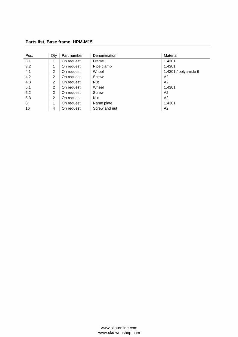
Parts list, Base frame, HPM-M15
Pos. Qty Part number Denomination Material 3.1 1 On request Frame 1.4301 3.2 1 On request Pipe clamp 1.4301 4.1 2 On request Wheel 1.4301 / polyamide 6 4.2 2 On request Screw A2 4.3 2 On request Nut A2 5.1 2 On request Wheel 1.4301 5.2 2 On request Screw A2 5.3 2 On request Nut A2 8 1 On request Name plate 1.4301 16 4 On request Screw and nut A2
www.sks-online.com www.sks-webshop.com
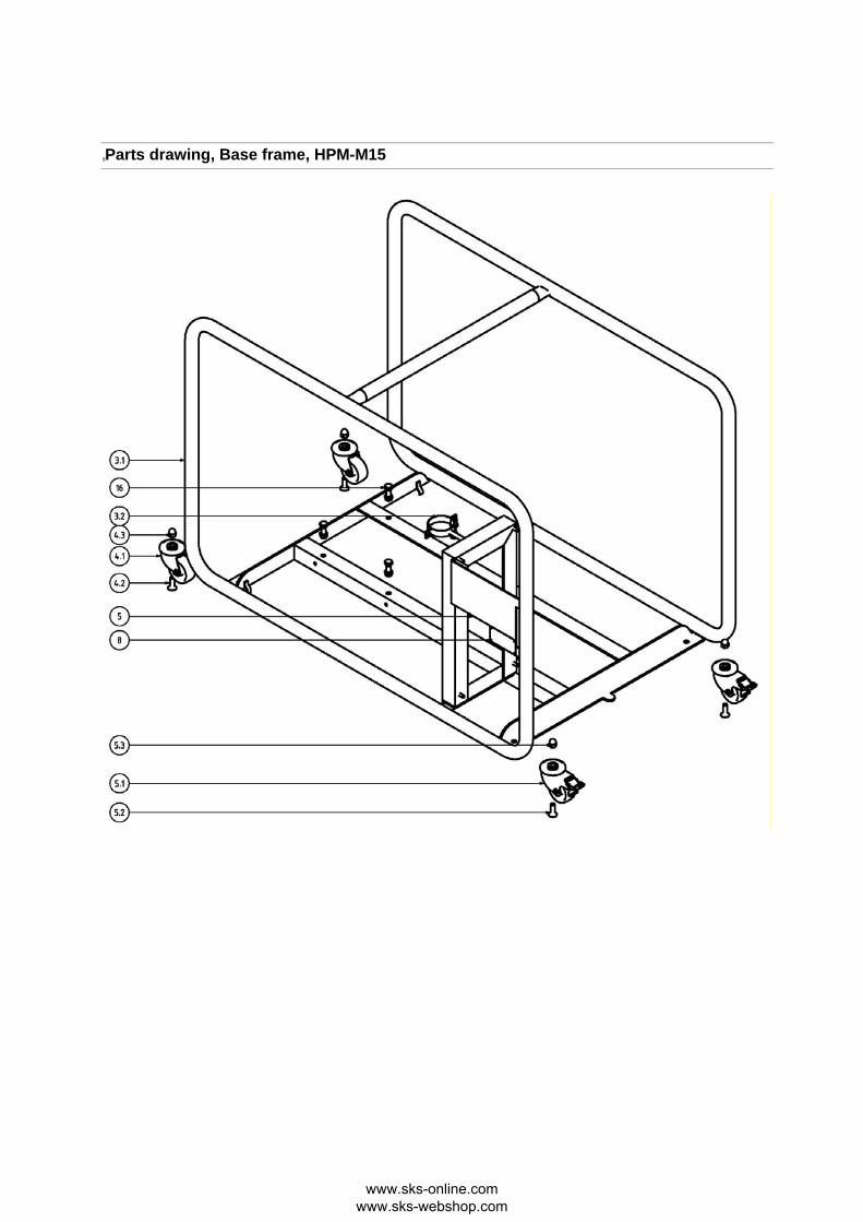
Parts drawing, Base frame, HPM-M15
www.sks-online.com www.sks-webshop.com

Parts list, Flush container, HPM-M15/HPM-S15
Pos. Qty Part number Denomination Material 7.1 1 On request Nut, union 1.4301 7.2 1 On request Sight glass Borosilicate 7.3 1 On request Seal EPDM 7.4 2 On request Tube connection 1.4404 7.5 1 On request Flush container house 1.4301 7.6 1 On request Seal NBR 7.7 1 9611291481 Blind cap 1.4301 7.8 2 On request Tube PTFE
Parts drawing, Flush container, HPM-M15/HPM-S15
www.sks-online.com www.sks-webshop.com

Parts list, C-ball valve, HPM-M15/HPM-S15
Pos. Qty Part number Denomination Material 10.1 1 9611900259 Seal EPDM 10.2 1 On request Handle 1.4301 10.3 1 On request Ball valve threaded part 1.4404 10.4 1 On request C-ball w. seal 1.4404/PTFE 10.5 1 On request Ball valve cone part 1.4404 10.6 4 On request Screw with nut A2
Parts drawing, C-ball valve, HPM-M15/HPM-S15
www.sks-online.com www.sks-webshop.com

Parts list, Inlet tube, HPM-M15/HPM-S15
Pos. Qty Part number Denomination Material 13.1 1 9612906208 O-ring seal EPDM 13.2 1 9611900256 Seal EPDM 13.3 1 On request Inlet tube 1.4404 13.4 1 9611900259 Seal EPDM
Parts drawing, Inlet tube
www.sks-online.com www.sks-webshop.com
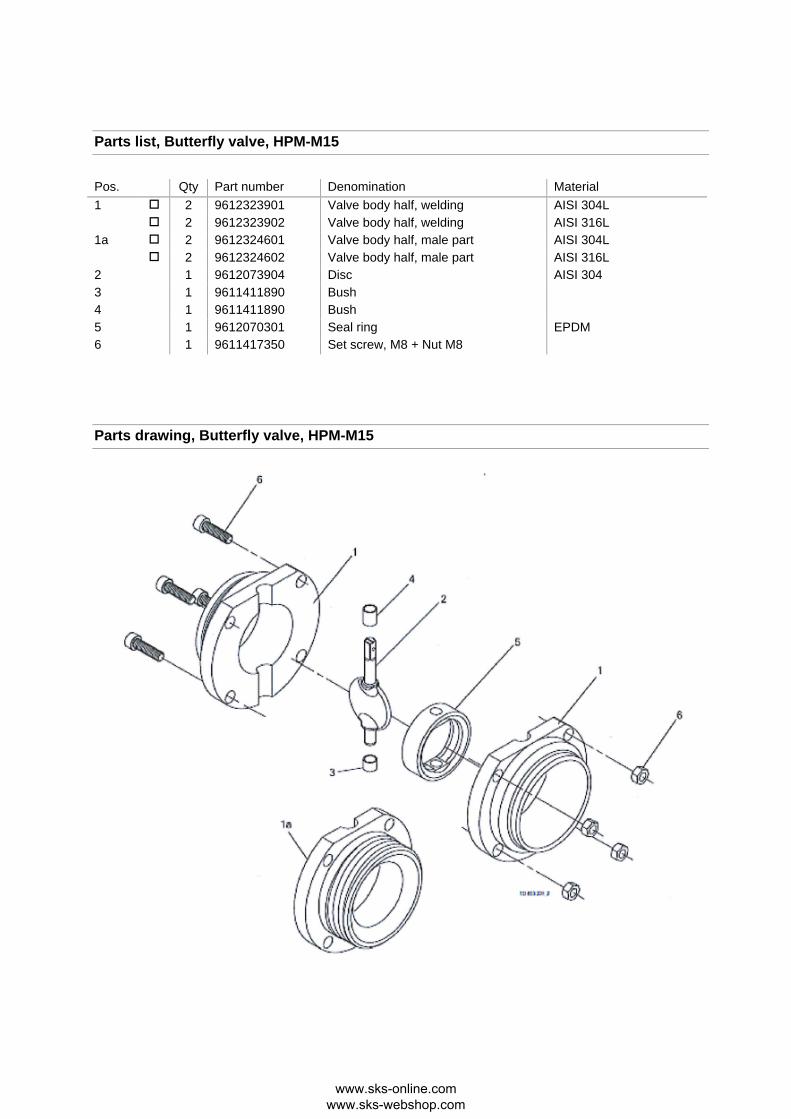
Parts list, Butterfly valve, HPM-M15
Pos. Qty Part number Denomination Material 1 2 9612323901 Valve body half, welding AISI 304L 2 9612323902 Valve body half, welding AISI 316L 1a 2 9612324601 Valve body half, male part AISI 304L 2 9612324602 Valve body half, male part AISI 316L 2 1 9612073904 Disc AISI 304 3 1 9611411890 Bush 4 1 9611411890 Bush 5 1 9612070301 Seal ring EPDM 6 1 9611417350 Set screw, M8 + Nut M8
Parts drawing, Butterfly valve, HPM-M15
www.sks-online.com www.sks-webshop.com

Parts list, High shear and pump unit, HPM-M15/HPM-S15
Pos. Qty Part number Denomination Material 42 1 On request Pump house 1.4404 32 1 9611992744 O-ring EPDM 45 1 On request Extension ring 1.4404 46 1 On request Rotor 1.4462 49 1 On request Front plate / Stator 1.4462/1.4404 Please see parts list for LKH-112 in separate pump manual - the parts above are either additional, revised or replaced by components of the LKH-112 pump.
www.sks-online.com www.sks-webshop.com

Parts drawing, High shear and pump unit, HPM-M15/HPM-S15
The drawing above is showing the ROW version - shroud pos. 2 is not included in the US/CANADA version since the motor is a Wash Down version
www.sks-online.com www.sks-webshop.com

Additional documents
See Annex, Operating instructions for frequency converter and pump.
www.sks-online.com www.sks-webshop.com

General Information
Service / Repair
The seals (both stationary and mechanical) are the same as on the standard LKH-112 pump - please see separate Spare Part documentation for LKH 112 pump where the seal material reference is SiC/SiC, EPDM. Be aware that there is an extra O-ring seal (ref. pos. 32 in Parts Drawing, High shear and pump unit) compared to the standard LKH 112 unit. All other seals - please find item numbers in the individual parts lists.
Warranty
The warranty conditions are subject to the legal warranty period of 12 months from the date of delivery. In case of improper use, modifications of or damages to the device, we do not accept warranty claims. Damaged devices will also not be accepted. Furthermore, defects due to normal wear are not subject to warranty services.
How to contact Alfa Laval
For further information please feel free to contact: Alfa Laval Tank Equipment Alfa Laval Kolding A/S
31, Albuen - DK 6000 Kolding - Denmark
Registration number: 30938011
Tel switchboard: +45 79 32 22 00 - Fax switchboard: +45 79 32 25 80
www.toftejorg.com , www.alfalaval.dk - [email protected]
Contact details for all countries are continually updated on our websites.
www.sks-online.com www.sks-webshop.com