Embed Size (px)
Citation preview

INSTRUCTION MANUAL
Smart Transmitter TerminalSTT04
PN25054

Copyright 2002 ABB Inc. [August 2002]
Trademarks and Registrations
Registrations and trademarks used in this document include:
® Windows Registered trademark of Microsoft Corporation® Windows NT Registered trademark of Microsoft Corporation® Lexan Registered trademark of General Electric Company, GE Plastics Division
WARNING notices as used in this manual apply to hazards or unsafe practices which could result in personalinjury or death.
CAUTION notices apply to hazards or unsafe practices which could result in property damage.
NOTES highlight procedures and contain information which assist the operator in understanding the informa-tion contained in this manual.
All software, including design, appearance, algorithms and source codes, is copyrighted by ABB Inc. and isowned by ABB Inc. or its suppliers.
WARNING
POSSIBLE PROCESS UPSETS. Maintenance must be performed only by qualified personnel and only aftersecuring equipment controlled by this product. Adjusting or removing this product while it is in the system mayupset the process being controlled. Some process upsets may cause injury or damage.
NOTICE
The information contained in this document is subject to change without notice.
ABB Inc., its affiliates, employees, and agents, and the authors of and contributors to this publication specifi-cally disclaim all liabilities and warranties, express and implied (including warranties of merchantability and fit-ness for a particular purpose), for the accuracy, currency, completeness, and/or reliability of the informationcontained herein and/or for the fitness for any particular use and/or for the performance of any material and/orequipment selected in whole or part with the user of/or in reliance upon information contained herein. Selectionof materials and/or equipment is at the sole risk of the user of this publication.
This document contains proprietary information of ABB Inc., and is issued in strict confidence. Its use, or repro-duction for use, for the reverse engineering, development or manufacture of hardware or software describedherein is prohibited. No part of this document may be photocopied or reproduced without the prior written con-sent of ABB Inc..

ABB Instrumentation
ADDENDUM
INTRODUCTION
This addendum supplements information contained in the WPBEEUI110502B0 STT04 Product Instruction. Thepurpose of this addendum is to "map" or corellate function keys on the revised STT04EBO keypad to the originalSTT04 keypad function keys that are documented in the Product Instruction. This addendum also providessupplemental 600TEN Transmitter information which is not contained in the existing STT04 Product Instruction.Refer to the STT04 Product Instruction for specific operating details.
OPERATOR/INTERFACE CONTROLS
The illustrations below show the comparison between the old and new STT04 keypads:
Old Keypad New Keypad
STT04EB_Smart Transmitter Terminal
PN24969COPYRIGHT 2000 ABB AUTOMATION INC. [May,2000]

ADDENDUM
2
Table 1 provides a comparison of old-keypad vs. new-keypad functions for the keys on the STT04 terminal.
NOTE: The configure, view, select device and options keys function without a field device connected to theSTT04 terminal. The other functions are locked out until a field device is connected to the terminal.
Table 1. Keypad Functions
Old Key New Key Function
Powers the unit up and displays the STT04 firmware revision level.
Turns power off. Stored configurations remain in internal memory. The termi-nal will shut itself off after 15 minutes of idle operation.
Scrolls through menus and selects functions.
Inputs values into the terminal. Includes digits 0 through 9, ASCII characters A through Z, signs, and punctuation.
Completes an input or a selection.
1. Inputs a new configuration into the STT04 internal memory.2. Modifies an existing configuration.3. Erases an existing configuration from the terminal memory.
Retrieves, views and optionally saves the configuration of the selected field device.
Sends a configuration from the STT04 terminal to a selected field device.
Steps through various calibration procedures (dependent on the selected field device).
Monitors primary input or output, secondary output, ambient temperature of the selected field device, and other variables.
O N
O FF
+ : / < > *
0% & G H I
9
E N TE R
C O N F IG
G E T C O N F IG
S EN D C O N FIG
C A LI- B R ATE
M O N ITO R

ADDENDUM
3
Displays field device status based on results of continuous self-diagnostics.
1. Changes engineering units.2. Sets lower and upper range values of primary and secondary units.3. Changes the output dampening.
1. Sets output to a fixed value.2. Cancels a fixed output.3. Sets up LCD - select display units to be displayed on the field device LCD.4. Changes device configuration to the standard configuration (PTS only).
NOTE: For special feature functions for the Type AVS Smart Positioner, refer to Appendix A.
Escapes the current function and returns the display to the READY condition.
Selects and changes working configurations and field devices (if connected).
Steps through the selections of the working configuration. Views a configura-tion, but does not allow modifications to be made.
1. Sets the language of the display screens.2. Sets the communication format.3. Displays the amount of charge left on the battery pack.4. Displays the STT04 name.
Returns to a previous screen during configuration, calibration, rerange, etc.
Table 1. Keypad Functions(continued)
Old Key New Key Function
S TATU S
R E - R A N G E
S PE C IALFE ATU RE
C LE AR
S ELE C T D E VIC E
V IEW
O P TIO N S
B AC K

ADDENDUM
4
APPENDIX - 600T & 600TEN PRESSURE TRANSMITTER
INTRODUCTION
This appendix covers the configuration and calibration functions of the Type 600T EN Pressure Transmitter. Refer to SECTION 4 - OPERATING PROCEDURES for information on the following functions:
CREATE/MODIFY CONFIGURATION
A configuration can be created off-line, without a connected field device. Refer to Figure 1 for an overview of theconfiguration function. The following table details the configuration process.
• Send configurations. • Select configurations.
• Get configurations. • Erase configurations.
• View configurations. • Operational functions.
Figure 1. Configuration Flowchart (600T & 600T EN)

ADDENDUM
5
Key Display Comments
Select NEW to create a configuration. To modify an existing configuration, select MODIFY. The screen sequence is the same, however, the MODIFY screens will appear with the values and arrow posi-tions as they were originally configured.
Select HART.
Select 600T.
Enter a name for the configuration ID tag using up to eight ASCII characters. To select a character, press the key that has the desired character. Continue to press the key until the desired character appears. Use the right arrow key to move to the next charac-ter. Use the left arrow key to go back to the previous character.
Select ANALOG.
NOTE: The DIGITAL selection should only be made when using an IMFBS01 field bus I/O module. A CHANNEL # prompt appears when DIGITAL is selected.
C O N F IG
E N TE R
CONFIGURATION→ NEW
MODIFYERASE
E N TE R
DEVICE TYPE
BAILEY FSK→ HART
[ 6 TIMES ]
E N TE R
TRANSMITTER TYPE PTH EBTH TB82 pH TB82 ORP TB82 pION TB82 CONC TZID/AXH AS800 TEU211 TS11/TS01 50XE4000 50XM2000 50SM‘1000 →600T HART UNIV
E N TE R
STT04 CONFIGURATION[ ]
←PREVIOUS NEXT→
E N TE R
SELECT MODE: → ANALOG
DIGITAL

ADDENDUM
6
Type a descriptive message using up to 32 charac-ters. This field can be used to note anything of impor-tance to the device or installation.
To select a character, press the key that has the desired character. Continue to press the key until the desired character appears. Use the right arrow key to move to the next character. Use the left arrow key to go back to the previous character.
Type a descriptor string using up to 16 characters. This field can be used for notations about the device or process.
To select a character, press the key that has the desired character. Continue to press the key until the desired character appears. Use the right arrow key to move to the next character. Use the left arrow key to go back to the previous character.
Enter a day and press . Enter a month and press . Enter a year and press .
This date can represent the creation date of the con-figuration, the date the device or element was installed, or some other significant date.
Select 600T EN
Select LINEAR.
NOTE: Other output type selections are:
SQUARE ROOT SQR (x^3) SQR (x^5) 5th ORDER POLYNOMIAL DOUBLE POLYN
Use to return to a previous configuration screen from any screen in the configuration process.
Enter a value between 0 and 16 seconds.
Key Display Comments
E N TE R
MESSAGE:
←PREVIOUS NEXT→
E N TE R
DESCRIPTOR:
←PREVIOUS NEXT→
E N TE R
DATE:DAY: nnMONTH: nnYEAR: nn
ENTERENTER ENTER
E N TE R
CONFIG TYPE600T
→ 600T EN
E N TE R
OUTPUT TYPE→ LINEAR
SQU (x)SQR (x^3)SQR (x^5)5th ORD. POLYDOUBLE POLYN
BACK
E N TE R
DAMPING:(0 - 16 SEC)
0.5 SECS

ADDENDUM
7
Select an engineering unit best suited for the application. Other units not shown include mmHg-0oC, PSI, BARS, mBAR, gSqCm, Kgcm2, PA, KPA, torr-0oC, ATM, MPa, iH2O-4oC, mmH2O-4oC.
Input lower range value using the number keys, then press . Input the upper range value, then press .
Select the 600T EN TEMPERATURE UNITS.Use arrow key to select option, then press
.
Select YES.
Key Display Comments
E N TE R
ENGINEERING UNIT→ iH20-20c iHg-0Oc
ftH2O-20c mmH20-20c
E N TE R
LOWER RANGE VALnn.nn UNITS
UPPER RANGE VALnn.nn UNITS
ENTERENTER
E N TE R
TEMPERATURE UNITS
→ °C °F °R °K ENTER
E N TE R
STORE THIS CONFIGURATION?
NO→ YES
E N TE R
ID TAGNAME
READY

ADDENDUM
8
CALIBRATION
This section details the 600T EN SUHVVXUH transmitter calibration functions using an STT04 terminal. There are fourtypes of calibration functions:
• Sensor Trim• D-to-A adjust (Analog Mode only)• PV Bias• Set Output %
Refer to Figure 2 for an overview of the calibration functions.
Figure 2. Calibration Flowchart (600T EN)

ADDENDUM
9
Sensor Trim
This procedure allows calibration of the pressure sensors for 600T EN pressure transmitters. Selections availableare FULL TRIM, ZERO TRIM, FACTORY TRIM and STATIC TRIM.
FULL TRIM
Use this option if both LOW (min.) and HIGH (max.) pressure settings are to be calibrated.
Key Display Comments
This operation will cause a change in output not cor-responding to the input. Be sure the control loop is in manual.
Select YES.
Select SENSOR TRIM, or select calibration option with down-arrow key and refer to the appropriate section. Press when done.
Select FULL TRIM.
Enter the low calibration pressure value using the number keys and press . Similarly, enter the high calibration pressure value, then press .
Apply the low calibration pressure to the input of transmitter as specified earlier.
Apply the high calibration pressure to the input of transmitter as specified earlier.
C A LI- B R ATE
E N TE R
OUTPUT WILL BEAFFECTED! PROCEED?
NO→ YES
E N TE R
→ SENSOR TRIMD-TO-A ADJUSTPV BIAS
SET OUTPUT % ENTER
E N TE R
→ FULL TRIMZERO TRIMFACTORY TRIM
STATIC TRIM
E N TE R
LOW CALIB PRESSUREnn.nn UNITS
HIGH CALIB PRESSUREnn.nn UNITS
ENTERENTER
E N TE R
APPLY PRESSURE OF nn.nn UNITS
THEN HIT ENTER
E N TE R
APPLY PRESSURE OFnn.nn UNITS
THEN HIT ENTER

ADDENDUM
10
ZERO TRIM
Use this option if only the LOW (min.) pressure setting is to be calibrated
Key Display Comments
This operation will cause a change in output not cor-responding to the input. Be sure the control loop is in manual.
Select YES.
Select SENSOR TRIM, or select calibration option with down-arrow key and refer to the appropriate section. Press when done.
Select ZERO TRIM.
Apply the pressure equal to the zero value of the instrument and press .
The instrument reads the pressure applied and dis-plays its value. Press .
C A LI- B R ATE
E N TE R
OUTPUT WILL BEAFFECTED! PROCEED?
NO→ YES
E N TE R
→ SENSOR TRIMD-TO-A ADJUSTPV BIAS
SET OUTPUT % ENTER
E N TE R
FULL TRIM→ ZERO TRIM
FACTORY TRIM STATIC TRIM
E N TE R
APPLY 0 INPUTTO SENSOR
THEN HIT ENTER
ENTER
E N TE R
APPLIED ZERO INPUT:value units
PRESS ENTERTO CONTINUE
ENTER
E N TE R
ID TAGNAME
READY

ADDENDUM
11
FACTORY TRIM
Use this option if factory setting is to be used for calibration.
Key Display Comments
This operation will cause a change in output not cor-responding to the input. Be sure the control loop is in manual.
Select YES.
Select SENSOR TRIM, or select calibration option with down-arrow key and refer to the appropriate section. Press when done.
Select FACTORY TRIM.
C A LI- B R ATE
E N TE R
OUTPUT WILL BEAFFECTED! PROCEED?
NO→ YES
E N TE R
→ SENSOR TRIMD-TO-A ADJUSTPV BIAS
SET OUTPUT % ENTER
E N TE R
FULL TRIMZERO TRIM
→ FACTORY TRIM STATIC TRIM
E N TE R
ID TAGNAME
READY

ADDENDUM
12
STATIC TRIM
Use this option if the instrument is to be statically calibrated using a known pressure.
Key Display Comments
This operation will cause a change in output not cor-responding to the input. Be sure the control loop is in manual.
Select YES.
Select SENSOR TRIM, or select calibration option with down-arrow key and refer to the appropriate section. Press when done.
Select STATIC TRIM.
Display shows the value of the pressure measured by the 600T EN transmitter.
Enter the value of the actual static pressure using the number keys.
C A LI- B R ATE
E N TE R
OUTPUT WILL BEAFFECTED! PROCEED?
NO→ YES
E N TE R
→ SENSOR TRIMD-TO-A ADJUSTPV BIAS
SET OUTPUT % ENTER
[ 3 TIMES ]
E N TE R
FULL TRIM ZERO TRIM
FACTORY TRIM→ STATIC TRIM
E N TE R
STATIC PRESSUREvalue units
PRESS ENTER TO MODIFY
E N TE R
STATIC PRESSURE
value units
E N TE R
ID TAGNAME
READY

ADDENDUM
13
D-to-A Adjust
The D-TO-A ADJUST selection is only present when you are in the ANALOG communication mode. There are threemethods available to adjust the four to 20 milliampere output:
• Up/Down Arrow keys. • Meter value entry for HART devices.• Factory DAC Trim
ARROW KEY ADJUSTMENT
Use this function to adjust the 4 to 20 milliampere output of the field device using the up and down arrow keys.
Key Display Comments
This operation will cause a change in output not cor-responding to the input. Be sure the control loop is in manual.
Select YES.
Select D-TO-A ADJUST.
Select UPDOWN ARROW KEYS.
Use the arrow keys to adjust the 4 mA signal.
NOTE: When increasing or decreasing the mA sig-nal, the increments of change increase with succes-sive depressions until the maximum level of change is reached. By changing direction you will return to the smallest increment of change. This adjustment technique speeds up the adjustment process without affecting fine adjustment.
C A LI- B R ATE
OUTPUT WILL BEAFFECTED! PROCEED?
NO→ YES
E N TE R
CALIBRATION SENSOR TRIM
→ D-TO-A ADJUSTPV BIAS
SET OUTPUT %
E N TE R
D/A CAL USING→ UPDOWN ARROW KEYS
METER VALUE ENTRY FACTORY DAC TRIM
E N TE R
ADJUST TO 4 mA
THEN HIT ENTER

ADDENDUM
14
METER VALUE ADJUSTMENT
Use this function to adjust the four to 20 milliampere output of the field device using values from an external currentmeter. This method is only valid for HART devices.
Use the arrow keys to adjust the 20 mA signal.
Key Display Comments
This operation will cause a change in output not cor-responding to the input. Be sure the control loop is in manual.
Select YES.
Select D-TO-A ADJUST.
Select METER VALUE ENTRY.
Key Display Comments
E N TE R
ADJUST TO 20 mA
THEN HIT ENTER
E N TE R
ID TAGNAME
READY
C A LI- B R ATE
E N TE R
OUTPUT WILL BEAFFECTED! PROCEED?
NO→ YES
E N TE R
CALIBRATION SENSOR TRIM
→ D-TO-A ADJUSTPV BIAS
SET OUTPUT %
E N TE R
D/A CAL USINGUPDOWN ARROW KEYS
→ METER VALUE ENTRY FACTORY DAC TRIM
ADDENDUM
15
PV Bias
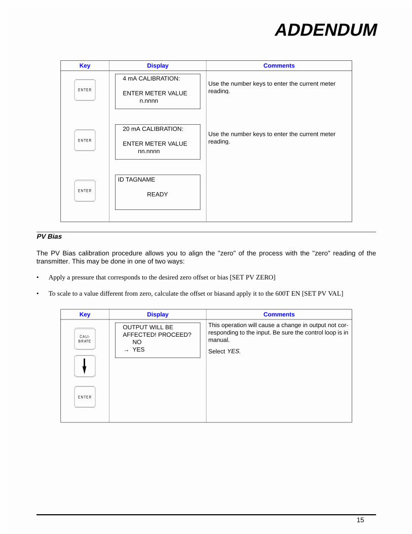
The PV Bias calibration procedure allows you to align the "zero" of the process with the "zero" reading of thetransmitter. This may be done in one of two ways:
• Apply a pressure that corresponds to the desired zero offset or bias [SET PV ZERO]
• To scale to a value different from zero, calculate the offset or biasand apply it to the 600T EN [SET PV VAL]
Use the number keys to enter the current meter reading.
Use the number keys to enter the current meter reading.
Key Display Comments
This operation will cause a change in output not cor-responding to the input. Be sure the control loop is in manual.
Select YES.
Key Display Comments
E N TE R
4 mA CALIBRATION:
ENTER METER VALUE n.nnnn
E N TE R
20 mA CALIBRATION:
ENTER METER VALUE nn.nnnn
E N TE R
ID TAGNAME
READY
C A LI- B R ATE
E N TE R
OUTPUT WILL BEAFFECTED! PROCEED?
NO→ YES

ADDENDUM
16
Select PV BIAS.
If digitally configured, the D-TO-A ADJUST selection will not appear.
Use the arrow keys to scroll to the desired PV BIAS parameter. RESET removes any previously config-ured bias values. The following procedure is used to establish the zero offset for SET PV ZERO, the pro-cedure for SET PV VAL is similar.
Apply the desired zero pressure value to the trans-mitter. Scroll to SET PV ZERO using the down arrow key and press .
Pressing calibrates the PV ZERO value.
SET PV ZERO is complete.
Key Display Comments
E N TE R
CALIBRATION SENSOR TRIM
D-TO-A ADJUST→ PV BIAS SET OUTPUT %
E N TE R
PV BIAS→ RESET
SET PV ZEROSET PV VAL
E N TE R
PV BIASRESET
→ SET PV ZEROSET PV VAL ENTER
E N TE R
PV VALUE READ: value unitsPRESS ENTERTO SET PV ZERO
ENTER
E N TE R
ID TAGNAME
READY

ADDENDUM
17
Set Outputt
Key Display Comments
This operation will cause a change in output not cor-responding to the input. Be sure the control loop is in manual.
Select YES.
Select SET OUTPUT %.
If digitally configured, the D-TO-A ADJUST selection will not appear.
Select LOW and press . (Procedure for HIGH selection is identical).
Display indicates present data.
Enter LOW value, .
C A LI- B R ATE
E N TE R
OUTPUT WILL BEAFFECTED! PROCEED?
NO→ YES
[ 3 TIMES ]
E N TE R
CALIBRATION SENSOR TRIM
D-TO-A ADJUSTPV BIAS
→ SET OUTPUT %
E N TE R
SET OUTPUT %→ LOW
HIGH
ENTER
E N TE R
OP %: nnn.nn %PV VAL:
value unitsHit ENTER to set OP%
E N TE R
ENTER NEW VALUE
value % ENTER
E N TE R
ID TAGNAME
READY

Table of Contents
PageSECTION 1 - INTRODUCTION....................................................................................................1-1
STT04 DESCRIPTION ....................................................................................................................1-1HOW TO USE THIS INSTRUCTION...............................................................................................1-2NOMENCLATURE ..........................................................................................................................1-3REFERENCE DOCUMENTS ..........................................................................................................1-3SPECIFICATIONS ..........................................................................................................................1-4OPTIONS AND ACCESSORIES.....................................................................................................1-4
SECTION 2 - DESCRIPTION AND OPERATION........................................................................2-1INTRODUCTION.............................................................................................................................2-1FUNCTIONAL OPERATION ...........................................................................................................2-1PHYSICAL OPERATION ................................................................................................................2-1
SECTION 3 - INSTALLATION .....................................................................................................3-1INTRODUCTION.............................................................................................................................3-1UNPACKING AND INSPECTION ...................................................................................................3-1SETUP AND PHYSICAL INSTALLATION ......................................................................................3-1
Charging STT04 Terminal .......................................................................................................3-2Clip Leads Cable Installation....................................................................................................3-2
DOWNLINK SOFTWARE................................................................................................................3-4System Requirements (Personal Computer) ...........................................................................3-4Installing DownLink Software ...................................................................................................3-4DownLink Software Practices ..................................................................................................3-4
SECTION 4 - OPERATING PROCEDURES................................................................................4-1INTRODUCTION.............................................................................................................................4-1HOW TO USE THE PROCEDURE TABLES ..................................................................................4-1OPERATOR/INTERFACE CONTROLS..........................................................................................4-1INITIAL START-UP .........................................................................................................................4-3SELECTING CHARACTERS FROM THE KEYPAD.......................................................................4-4VIEW AND SELECT CONFIGURATION.........................................................................................4-6SEND CONFIGURATION ...............................................................................................................4-7GET CONFIGURATION .................................................................................................................4-8ERASE CONFIGURATION ..........................................................................................................4-10OPERATIONAL FUNCTIONS.......................................................................................................4-11
Special Feature Key...............................................................................................................4-12FIX OUTPUT/CANCEL FIX OUTPUT.............................................................................4-12LCD SETUP....................................................................................................................4-13STANDARD CONFIGURATION .....................................................................................4-14RESET CONFIGURATION CHANGE FLAG ..................................................................4-15
Monitor Key Functions ...........................................................................................................4-16MONITOR PRIMARY OUTPUT......................................................................................4-16MONITOR PRIMARY INPUT..........................................................................................4-17MONITOR SECONDARY UNITS OUTPUT....................................................................4-18TEMPERATURE FUNCTION .........................................................................................4-18
Status Check..........................................................................................................................4-19Rerange Key Function ...........................................................................................................4-19
i

Table of Contents (continued)
PageOptions Key Functions ...........................................................................................................4-21
LANGUAGE ....................................................................................................................4-21COMMUNICATION FORMAT.........................................................................................4-22BATTERY........................................................................................................................4-22STT04 NAME ..................................................................................................................4-23STT04 REVISION ...........................................................................................................4-24
UPLOADING AND DOWNLOADING CONFIGURATIONS...........................................................4-25
SECTION 5 - TROUBLESHOOTING...........................................................................................5-1INTRODUCTION .............................................................................................................................5-1ERROR MESSAGES.......................................................................................................................5-1
SECTION 6 - REPAIR/REPLACEMENT AND UPGRADE..........................................................6-1INTRODUCTION .............................................................................................................................6-1SPECIAL HANDLING GUIDLINES FOR MOS DEVICES...............................................................6-1REPLACING THE BATTERY PACK ...............................................................................................6-2UPGRADES ....................................................................................................................................6-3DOWNLOADING AN UPGRADE TO THE STT04 TERMINAL .......................................................6-5RECOMMENDED SPARE PARTS..................................................................................................6-6
SECTION 7 - MAINTENANCE.....................................................................................................7-1INTRODUCTION .............................................................................................................................7-1CLEANING ......................................................................................................................................7-1
SECTION 8 - SUPPORT SERVICES...........................................................................................8-1INTRODUCTION .............................................................................................................................8-1REPLACEMENT PARTS.................................................................................................................8-1SPARE PARTS LISTS ....................................................................................................................8-1TRAINING .......................................................................................................................................8-1TECHNICAL DOCUMENTATION....................................................................................................8-1
APPENDIX A - SMART POSITIONER ...................................................................................... A-1INTRODUCTION ............................................................................................................................ A-1CREATE/MODIFY CONFIGURATION........................................................................................... A-1CALIBRATION................................................................................................................................ A-5
Output D-to-A Calibration ........................................................................................................ A-6Input A-to-D Calibration........................................................................................................... A-7Manual Position Calibration..................................................................................................... A-8Automatic Position Calibration................................................................................................. A-9
SPECIAL FEATURE KEY FUNCTIONS....................................................................................... A-10Fix Set Point/Cancel Fix Set Point......................................................................................... A-10PID Parameters ..................................................................................................................... A-11Reset Totals .......................................................................................................................... A-12Monitor Key Functions........................................................................................................... A-13
ii

Table of Contents (continued)
PageAPPENDIX B - EBTH TEMPERATURE TRANSMITTER........................................................... B-1
INTRODUCTION............................................................................................................................ B-1CREATE/MODIFY CONFIGURATION........................................................................................... B-1CALIBRATION ............................................................................................................................... B-5
Bench Calibration.................................................................................................................... B-6D-to-A Adjust ........................................................................................................................... B-7
ARROW KEY ADJUSTMENT.......................................................................................... B-8METER VALUE ADJUSTMENT ...................................................................................... B-9
APPENDIX C - EQS TEMPERATURE TRANSMITTER.............................................................C-1INTRODUCTION............................................................................................................................ C-1CREATE/MODIFY CONFIGURATION........................................................................................... C-1CALIBRATION ............................................................................................................................... C-4
Bench Calibration.................................................................................................................... C-4D-to-A Adjust ........................................................................................................................... C-7
APPENDIX D - PTH PRESSURE TRANSMITTER..................................................................... D-1INTRODUCTION............................................................................................................................ D-1CREATE/MODIFY CONFIGURATION........................................................................................... D-1CALIBRATION .............................................................................................................................. D-5
Bench Calibration.................................................................................................................... D-6Rezero .................................................................................................................................... D-8D-to-A Adjust ........................................................................................................................... D-8
ARROW KEY ADJUSTMENT.......................................................................................... D-9METER VALUE ADJUSTMENT .................................................................................... D-10
APPENDIX E - PTS PRESSURE TRANSMITTER ..................................................................... E-1INTRODUCTION............................................................................................................................ E-1CREATE/MODIFY CONFIGURATION........................................................................................... E-1CALIBRATION .............................................................................................................................. E-4
Bench Calibration.................................................................................................................... E-4Rezero .................................................................................................................................... E-7D-to-A Adjust ........................................................................................................................... E-8
APPENDIX F - HART UNIVERSAL ............................................................................................ F-1INTRODUCTION.............................................................................................................................F-1HART UNIVERSAL CONFIGURATION ..........................................................................................F-1
APPENDIX G - BCN PRESSURE TRANSMITTER....................................................................G-1INTRODUCTION............................................................................................................................ G-1CREATE/MODIFY CONFIGURATION........................................................................................... G-1CALIBRATION ...............................................................................................................................G-5
Bench Calibration....................................................................................................................G-5Rezero .................................................................................................................................... G-8D-to-A Adjust ........................................................................................................................... G-9
iii

Table of Contents (continued)
PageAPPENDIX H - EQN TEMPERATURE TRANSMITTER ............................................................ H-1
INTRODUCTION ............................................................................................................................H-1CREATE/MODIFY CONFIGURATION...........................................................................................H-1CALIBRATION................................................................................................................................H-4
Bench Calibration ....................................................................................................................H-5D-to-A Adjust ...........................................................................................................................H-7
APPENDIX I - XM/SM/XE MAGNETIC FLOWMETER .................................................................I-1INTRODUCTION ..............................................................................................................................I-1CREATE/MODIFY CONFIGURATION.............................................................................................I-1CALIBRATION..................................................................................................................................I-5
Empty Pipe Detector .................................................................................................................I-6D-to-A Adjust ............................................................................................................................I-7
APPENDIX J - TBN480 CONDUCTIVITY TRANSMITTER.........................................................J-1INTRODUCTION .............................................................................................................................J-1CREATE/MODIFY CONFIGURATION............................................................................................J-1CALIBRATION.................................................................................................................................J-5
Process Calibration ..................................................................................................................J-5CALIBRATE PROCESS CONDUCTIVITY........................................................................J-6CALIBRATE PROCESS TEMPERATURE........................................................................J-7
Editing the Calibration Constants .............................................................................................J-8EDIT CONDUCTIVITY ......................................................................................................J-8EDIT TEMPERATURE......................................................................................................J-9
Reset to Factory Configuration...............................................................................................J-11
APPENDIX K - TBN580 TRANSMITTER ................................................................................... K-1INTRODUCTION ............................................................................................................................ K-1CREATE/MODIFY CONFIGURATION........................................................................................... K-1CALIBRATION ............................................................................................................................... K-5
Process Calibration ................................................................................................................. K-6Bench Calibration pH .............................................................................................................. K-7Bench Calibration Temperature............................................................................................. K-10D-to-A Adjust ......................................................................................................................... K-11
APPENDIX L - TBN581 (ORP/pION) TRANSMITTER................................................................L-1INTRODUCTION .............................................................................................................................L-1CREATE/MODIFY CONFIGURATION............................................................................................L-1CALIBRATION.................................................................................................................................L-4
Process Calibration ..................................................................................................................L-5Bench Calibration (ORP/pION).................................................................................................L-6Bench Calibration (mV) ............................................................................................................L-8D-to-A Adjust ............................................................................................................................L-9
APPENDIX M - TZID/AZH POSITIONER ...................................................................................M-1INTRODUCTION ............................................................................................................................M-1CREATE/MODIFY CONFIGURATION...........................................................................................M-1CALIBRATION ...............................................................................................................................M-5
Autostroke Calibration .............................................................................................................M-5Manual Range Adjustment .....................................................................................................M-6Lever Zero Position .................................................................................................................M-7
iv
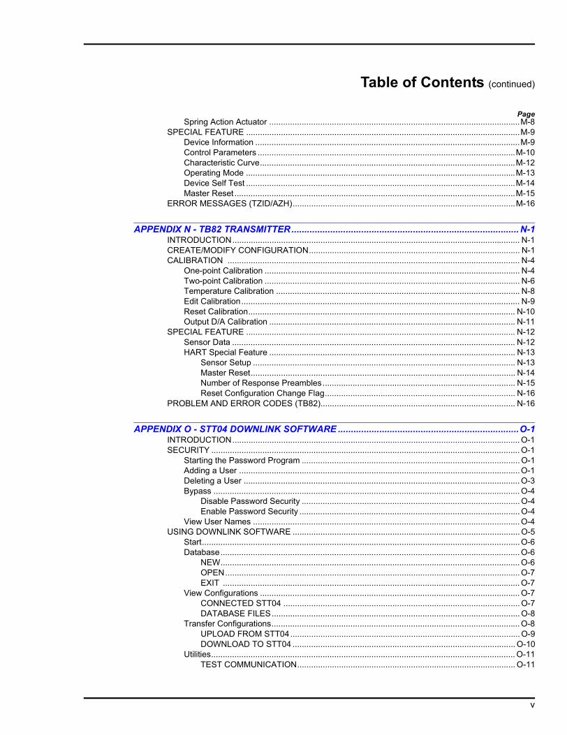
Table of Contents (continued)
PageSpring Action Actuator ............................................................................................................M-8
SPECIAL FEATURE ......................................................................................................................M-9Device Information ..................................................................................................................M-9Control Parameters ...............................................................................................................M-10Characteristic Curve..............................................................................................................M-12Operating Mode ....................................................................................................................M-13Device Self Test ....................................................................................................................M-14Master Reset .........................................................................................................................M-15
ERROR MESSAGES (TZID/AZH)................................................................................................M-16
APPENDIX N - TB82 TRANSMITTER........................................................................................ N-1INTRODUCTION............................................................................................................................ N-1CREATE/MODIFY CONFIGURATION........................................................................................... N-1CALIBRATION .............................................................................................................................. N-4
One-point Calibration .............................................................................................................. N-4Two-point Calibration .............................................................................................................. N-6Temperature Calibration ......................................................................................................... N-8Edit Calibration........................................................................................................................ N-9Reset Calibration................................................................................................................... N-10Output D/A Calibration .......................................................................................................... N-11
SPECIAL FEATURE .................................................................................................................... N-12Sensor Data .......................................................................................................................... N-12HART Special Feature .......................................................................................................... N-13
Sensor Setup ................................................................................................................. N-13Master Reset.................................................................................................................. N-14Number of Response Preambles................................................................................... N-15Reset Configuration Change Flag.................................................................................. N-16
PROBLEM AND ERROR CODES (TB82).................................................................................... N-16
APPENDIX O - STT04 DOWNLINK SOFTWARE ......................................................................O-1INTRODUCTION............................................................................................................................ O-1SECURITY ..................................................................................................................................... O-1
Starting the Password Program .............................................................................................. O-1Adding a User .........................................................................................................................O-1Deleting a User ....................................................................................................................... O-3Bypass .................................................................................................................................... O-4
Disable Password Security .............................................................................................. O-4Enable Password Security ............................................................................................... O-4
View User Names ................................................................................................................... O-4USING DOWNLINK SOFTWARE .................................................................................................. O-5
Start.........................................................................................................................................O-6Database................................................................................................................................. O-6
NEW................................................................................................................................. O-6OPEN...............................................................................................................................O-7EXIT ................................................................................................................................ O-7
View Configurations ................................................................................................................ O-7CONNECTED STT04 ...................................................................................................... O-7DATABASE FILES........................................................................................................... O-8
Transfer Configurations........................................................................................................... O-8UPLOAD FROM STT04...................................................................................................O-9DOWNLOAD TO STT04 ................................................................................................ O-10
Utilities................................................................................................................................... O-11TEST COMMUNICATION.............................................................................................. O-11
v

Table of Contents (continued)
PageCHANGE STT04 NAME.................................................................................................O-12
Special Advanced..................................................................................................................O-13REPORT DIAGNOSTICS...............................................................................................O-13UPGRADE FIRMWARE.................................................................................................O-13UPGRADE BOOT CODE...............................................................................................O-13SET COM PORT............................................................................................................O-13
APPENDIX P - AS800 PRESSURE TRANSMITTER ................................................................. P-1INTRODUCTION ............................................................................................................................ P-1CREATE/MODIFY CONFIGURATION........................................................................................... P-1CALIBRATION ............................................................................................................................... P-5
Input A/D ................................................................................................................................. P-6D-to-A Adjust ........................................................................................................................... P-7
ARROW KEY ADJUSTMENT .......................................................................................... P-7METER VALUE ADJUSTMENT....................................................................................... P-8
Zero Trim Calibration .............................................................................................................. P-9Temperature Calibration........................................................................................................ P-10
APPENDIX Q - 600T & 600T EN PRESSURE TRANSMITTER................................................1-13INTRODUCTION ...........................................................................................................................1-13CREATE/MODIFY CONFIGURATION..........................................................................................1-13CALIBRATION ..............................................................................................................................1-17
Sensor Trim............................................................................................................................1-18FULL TRIM......................................................................................................................1-18ZERO TRIM ....................................................................................................................1-19FACTORY TRIM .............................................................................................................1-20STATIC TRIM..................................................................................................................1-21
D-to-A Adjust ..........................................................................................................................1-22ARROW KEY ADJUSTMENT .........................................................................................1-22METER VALUE ADJUSTMENT......................................................................................1-23
PV Bias ..................................................................................................................................1-24Set Output % ..........................................................................................................................1-26
List of FiguresNo. Title Page
1-1. STT04 Smart Transmitter Terminal ..........................................................................................1-12-1. Analog Point-to-Point Communications Wiring.........................................................................2-22-2. ABB Digital Field Bus and HART Wiring ..................................................................................2-23-1. Receptacle Locations ...............................................................................................................3-23-2. Analog Point-to-Point Wiring ....................................................................................................3-33-3. Digital Field Bus and HART Wiring...........................................................................................3-46-1. Internal Component Locations .................................................................................................6-3A-1. Configuration Flowchart (AVS) ................................................................................................ A-1A-2. Calibration Flowchart (AVS) .................................................................................................... A-5B-1. Configuration Flowchart (EBTH).............................................................................................. B-1B-2. Calibration Flowchart (EBTH).................................................................................................. B-5C-1. Configuration Flowchart (EQS)................................................................................................C-1C-2. Calibration Flowchart (EQS)....................................................................................................C-5
vi

List of Figures (continued)
No. Title Page
D-1. Configuration Flowchart (PTH)................................................................................................ D-1D-2. Calibration Flowchart (PTH) .................................................................................................... D-5E-1. Configuration Flowchart (PTS) ................................................................................................ E-1E-2. Calibration Flowchart (PTS) .................................................................................................... E-5F-1. Configuration Flowchart (HART) ..............................................................................................F-1G-1. Configuration Flowchart (BCN) ............................................................................................... G-1G-2. Calibration Flowchart (BCN) ...................................................................................................G-5H-1. Configuration Flowchart (EQN) ............................................................................................... H-1H-2. Calibration Flowchart (EQN) ................................................................................................... H-5I-1. Configuration Flowchart (XM/SM/XE Mag Flow)....................................................................... I-1I-2. Calibration Flowchart (XM/SM/XE Mag Flow)........................................................................... I-6J-1. Configuration Flowchart (TBN480)........................................................................................... J-1J-2. Calibration Flowchart (TBN480)............................................................................................... J-5K-1. Configuration Flowchart (TBN580).......................................................................................... K-1K-2. Calibration Flowchart (TBN580).............................................................................................. K-5L-1. Configuration Flowchart (TBN581)...........................................................................................L-1L-2. Calibration Flowchart (TBN581)...............................................................................................L-5M-1. Configuration Flowchart (TZID/AZH).......................................................................................M-1M-2. Calibration Flowchart (TZID/AZH)...........................................................................................M-5N-1. Configuration Flowchart (TB82) .............................................................................................. N-1N-2. Calibration Flowchart (TB82) .................................................................................................. N-4O-1. Password Key Screen............................................................................................................. O-2O-2. Add User Dialog Box............................................................................................................... O-2O-3. DownLink Software Screen ..................................................................................................... O-6O-4. Summary of STT04 Configurations......................................................................................... O-9O-5. Replace Configuration File Dialog......................................................................................... O-10P-1. Configuration Flowchart (AS800) ............................................................................................ P-1P-2. Calibration Flowchart (AS800) ................................................................................................ P-5
List of TablesNo. Title Page
1-1. STT04 Terminal Device Support ..............................................................................................1-21-2. STT04 Nomenclature ...............................................................................................................1-41-3. Reference Documents ............................................................................................................1-41-4. Glossary of Terms and Abbreviations ......................................................................................1-51-5. STT04 Terminal Specifications ...............................................................................................1-53-1. System Requirements..............................................................................................................3-44-1. Keypad Functions ...................................................................................................................4-24-2. Languages .............................................................................................................................4-255-1. STT04 Error Messages for ABB FSK Devices .......................................................................5-15-2. STT04 Error Messages for HART Devices ............................................................................5-86-1. Upgrade Languages.................................................................................................................6-56-2. List of Spare Parts....................................................................................................................6-5M-1. Error Messages for TZID/AZH Positioner .............................................................................M-16N-1. Problem Codes of TB82 Transmitter .................................................................................... N-17N-2. Error Codes of the TB82 Transmitter .................................................................................... N-23O-1. User Level Accessibility .......................................................................................................... O-3O-2. Software Function Summary ..................................................................................................O-5
vii

Read First I
Read First
WARNING
INSTRUCTION MANUALSDo not install, maintain or operate this equipment without reading,
understanding and following the proper factory-supplied instructions and manuals, otherwise injury or damage may result.
RETURN OF EQUIPMENTAll equipment being returned to the factory for repair must be free of any hazardous materials (acids, alkalis, solvents, etc.). A Material Safety Data
Sheet (MSDS) for all process liquids must accompany returned equipment. Contact the factory for authorization prior to returning equipment.
Read these instructions before starting installation;save these instructions for future reference.
Contacting the Factory . . .
Should assistance be required with any of the companys products, contact the following:
Telephone:
24-Hour Call Center1-800-HELP-365
E-Mail:

SECTION 1 - INTRODUCTION
STT04 DESCRIPTION
The STT04 Smart Transmitter Terminal is a battery powered, portablecommunication device that configures, calibrates, monitors, modifies,troubleshoots, and verifies the operation of HART devices and ABBsmart devices from remote locations (Fig. 1-1).
The STT04 Smart Transmitter Terminal consists of an LCD display,key pad (32 keys) and an RS-232-C port for personal computer com-munications. The terminal comes with a clip lead cable, batterycharger and an optional carrying case.
The STT04 terminal can operate for approximately six days beforeneeding a charge. Each terminal includes a battery charger.
The STT04 terminal supports HART devices and ABB Digital FSKdevices. Refer to Table 1-1 for a list of devices.
Figure 1-1. STT04 Smart Transmitter Terminal
LCD DISPLAY
BATTERY CHARGERRECEPTACLE
KEY PAD
RS-232 PORT
COMMUNICATIONSRECEPTACLE
T01540A
STT04 DESCRIPTION 1 - 1

INTRODUCTION
HOW TO USE THIS INSTRUCTION
Read this instruction completely through in sequence. It is importantto become familiar with the entire contents of this instruction beforeusing the STT04 terminal. After reading:
1. Perform the steps in Section 3. Make sure all hardware isinstalled properly before connecting the STT04 terminal.
2. Refer to Section 4 after installation is complete for information onthe use of the STT04 terminal.
3. Refer to the appropriate appendix when configuring and calibrat-ing a field device.
4. Each device has a configuration worksheet located at the back ofthis instruction. Use the worksheets to keep a hard copy record of thedevice configuration.
This document uses the following text conventions:
Bold Italic Text Refers to specific section names through out this instruction.
Display Item Shows display items as they appear on the STT04 terminal.
Shows the actual keys that are pressed when in procedural steps.
nnn Indicates numeric values in a display.
Table 1-1. STT04 Terminal Device Support
Type DeviceHART EBTH
HART Universal1
PTHTB82TZID/AZH
ABB FSK AVSBCNEQNEQSPTSTBN480TBN580TBN581XE/SM/XE
NOTE: 1. Used to communicate with unsupported HART devices.
KEY
HOW TO USE THIS INSTRUCTION1 - 2

INTRODUCTION
NOMENCLATURE
Table 1-2 lists the nomenclature selections for the STT04 terminal.
REFERENCE DOCUMENTS
Table 1-3 lists the instructions related to the STT04 terminal.
Table 1-2. STT04 NomenclaturePosition 1 2 3 4 5 6
Type S T T Smart Transmitter Terminal
Option0 Terminal only1 Terminal with soft carrying case
Revision level4 Revision level
Keypad insertE EnglishF FrenchS Spanish
Table 1-3. Reference Documents
Number DocumentI-E21-31 Smart Electronic Pressure Transmitter BCN1I-E21-32 Smart Electronic Pressure Transmitter BCN2/3/4/5/6/8I-E21-37 Smart Electronic Level Transmitter BCN7I-E21-50-1 Platinum Standard Series Smart Pressure Transmitter PTSDI-E21-50-2 Platinum Standard Series Smart Level Transmitter PTSDLPN25053 Platinum Standard Series Smart Pressure Transmitter PTSPPN25051 Platinum Standard Series HART Pressure Transmitter PTHDI-E21-54-2 Platinum Standard Series HART Level Transmitter PTHDLPN25052 Platinum Standard Series HART Pressure Transmitter PTHPI-E51-79 Smart Temperature Transmitter EQNI-E51-80-001 Platinum Standard Series Smart Temperature Transmitter EQSI-E67-38 Smart pH/ORP Specific Ion Transmitter Series TBN580/581I-E67-42 Smart Conductivity Transmitter Series TBN480I-E96-302 Field Bus Module IMFBS01 WBPEEUI110503A0 Platinum Standard Series HART Temperature Transmitter EBTHWBPEEUI120752A0 Smart Positioner AVSWBPEEUI520002A0 Advantage Series pH/ORP/pION Transmitter TB8242/18-54-EN TZID/AZH PositionerPN 25041 Magnetic Flow Meter XM-Series
NOMENCLATURE 1 - 3

INTRODUCTION
SPECIFICATIONS
Table 1-4 lists the performance specifications of the STT04 terminal.
OPTIONS AND ACCESSORIES
The STT04 has a nomenclature option for a carrying case, refer toTable 1-2 for nomenclature details. Spare parts are recommended tobe kept on hand to minimize down time, refer to REPAIR/REPLACE-MENT AND UPGRADE in Section 6 for spare parts information.
Table 1-4. STT04 Terminal Specifications
Property Characteristic/ ValueDisplay format
TypeNumber of rowsCharacters per row
LCD420
Configuration storage capacity
100 configurations
Keyboard type Tactile feedback embossed membrane; 32 keysClip Leads Cable length 1.8 m (5 ft 10 in.)Temperature limits
OperatingStorage
-10° to 60°C (14° to 140°F) -20° to 70°C (-4° to 158°F)
Humidity limits 95%, noncondensingBatteries
TypeRun timeCharging time
AA NiCd rechargeable6 days (approximately)2.8 hours
Weight 635 g (22.4 oz)Dimensions (HxWxD) 200 x 108 x 44 mm (7.875 x 4.25 x 1.75 in)Case material Plastic, polycarbonate (Lexan 940® or
equivalent)Agency certifications1 Factory Mutual (FM) approval and Canadian
Standards Association (CSA) certifications in the following categories:
Nonincendive:
Class I; Division 2; Groups A, B, C, D
Intrinsically Safe:
Class I; Division 1; Groups A, B, C, DNOTE: 1. Hazardous location approvals for use in flammable atmospheres are for ambient conditions of-25° to 40°C (-13° to 104°F), 86 to 106 kPa (12.5 to 15.7 psi) with a maximum oxygen concentrationof 21 percent.
SPECIFICATIONS SUBJECT TO CHANGE WITHOUT NOTICE
SPECIFICATIONS1 - 4

SECTION 2 - DESCRIPTION AND OPERATION
INTRODUCTION
This section describes the operational modes of the STT04 SmartTransmitter Terminal and contains diagrams of the wiring connectionsbetween the field device and the terminal.
FUNCTIONAL OPERATION
The STT04 terminal operates with a field device by attaching clipleads from the terminal to the signal wires of the field device. Commu-nication occurs over the signal wires.
The STT04 terminal and field devices communicate by using any ofthe following communication methods:
HART A slow speed (1,200 baud) communication standard established byHART communications foundation (specification 5.0). The communi-cation signal is a high frequency AC waveform with a zero DC aver-age. It has no effect on the transmitter output. This communicationsmethod provides exceptional noise immunity.
ABB FSK High speed (9,600 baud) frequency shift keying is a form of frequencymodulation used for digital communication. The communication sig-nal is a high frequency AC signal with a DC average of zero. There-fore, digital communication and process variable output can occursimultaneously. Communicates with up to eight devices when inter-facing the ABB digital field bus.
PHYSICAL OPERATION
The STT04 terminal connects to the field device anywhere there isaccess to the signal leads of the transmitter. The STT04 terminalmust be connected between the device and the 250 ohm resistance.The clip leads connect across the signal leads independent of signaldirection or polarity. Refer to Figures 2-1 and 2-2.
Batteries and length of charge can be operated with the charger con-nected.
INTRODUCTION 2 - 1

DESCRIPTION AND OPERATION
Figure 2-1. Analog Point-to-Point Communications Wiring
Figure 2-2. ABB Digital Field Bus and HART Wiring
T01323B
ST T
+––
–
++
C O M M U N IC AT IO N S A R EN OT P O S S IB LE O N TH IS
S ID E O F 250- R E S IS TO RΩ
C O M M U N IC ATIO N S AR EP O S SIBLE O N TH IS S ID E
O F 250- R E SIS TO RΩ
S IG N A L W IR E S
FIE LD D E VIC E
U P TO 1 M I. (1 .6 K M )
SY S TE M P OW E RS U P P LY
PW R /O U T PU T
C O N T RO LLE R ,R E C O R D E R O R
C O N TRO L SY S TE M
250 Ω
T01324B
ST T
SIG N A L W IR E ST E R M IN AT IO N
U N ITFIE LD BU S
I/O M O D U LE M F P /M FC
– –
+ +
F IE LD D E V IC E 1 FIE LD D E V IC E 8
P W R /O U TP U T
P W R /O U T PU T
PHYSICAL OPERATION2 - 2

SECTION 3 - INSTALLATION
INTRODUCTION
This section provides procedures that make the STT04 terminal oper-ational.
UNPACKING AND INSPECTION
Before unpacking, carefully examine the exterior of the shipping con-tainer for evidence of in-transit damage. Inspect for punctures, tearsor other damage that penetrates the outer container, and for evidenceof water damage.
The shipping package contains the following:
• STT04 Smart Transmitter Terminal.
• Clip leads cable.
• DownLink Software CD (STT04 firmware or later).
• STT04 carrying case (optional).
NOTE: If STT04 firmware is A.0, DownLink Software is not includedwith the firmware. Contact the nearest ABB sales office for softwareavailability.
Examine the exterior of the STT04 terminal for physical defects.
If storing the terminal prior to operation, pack in the original container,if possible. Store in an area free of extremes in temperature andhumidity.
SETUP AND PHYSICAL INSTALLATION
The only installation task is the connection of the provided clip leads.Otherwise, the STT04 terminal comes fully assembled and opera-tional.
INTRODUCTION 3 - 1

INSTALLATION
Charging STT04 Terminal
Periodically the battery unit requires charging. Use the batterycharger, ABB part number 1949616?A for North American 60 Hz plugconfiguration. Contact your local ABB sales office for internationalplug configurations.
With a full charge, the STT04 terminal can operate for approximatelysix days before needing a charge.
To charge the STT04 terminal:
1. Insert the male end of the battery charger into the battery chargerreceptacle on the STT04 terminal (Fig. 3-1).
2. Plug the charger into a 120 VAC, 50/60 Hz outlet. Contact yourlocal ABB sales office for international plug configurations.
3. Allow the terminal to charge at least one hour before operating. Afull charge takes approximately 2.8 hours. The terminal can operatewhile recharging is in progress.
Clip Leads Cable Installation
The STT04 terminal communicates with a field device by attachingthe clip leads from the terminal to the signal wires of the field device.
WARNING To prevent ignition of a hazardous atmosphere, batteries mustonly be charged in an area known to be nonhazardous.
Figure 3-1. Receptacle Locations
BATTE RY C H AR G E RR E C EP TAC L E
T 01 99 7 A
C LIP LE AD S C AB LER E C EP TAC L E
SETUP AND PHYSICAL INSTALLATION3 - 2

INSTALLATION
To install the clip leads cable:
1. Insert the female end of the clip leads cable connector into theclip leads cable receptacle on the terminal with the button facing up(Fig. 3-1). Make sure the connector is fully engaged.
2. Connect the clip leads to the signal wires between the device andthe 250 ohm resistance. The clip leads connect across the signalleads independent of signal direction or polarity. Refer to Figures 3-2and 3-3.
To remove the clip leads cable:
1. Fully depress and hold in the button on the top of the clip leadscable connector.
2. Firmly, but carefully pull the connector from the receptacle.
Figure 3-2. Analog Point-to-Point Wiring
Figure 3-3. Digital Field Bus and HART Wiring
T01323B
S T T
+––
–
++
C O M M U N IC AT IO N S A R EN OT P O S S IB L E O N T H IS
S ID E O F 250- R E S IS TO RΩ
C O M M U N IC AT IO N S A R EP O S S IB L E O N T H IS S ID E
O F 250- R E S IS TO RΩ
S IG N A L W IR E S
F IE L D D E V IC E
U P TO 1 M I. (1 .6 K M )
S Y S T E M P OW E RS U P P LY
P W R /O U TP U T
C O N TRO L LE R ,R E C O R D E R O R
C O N T RO L S Y S T E M
250 Ω
T01 324B
ST T
S IG N AL W IR E S TER M IN ATIO NU N IT
F IELD BU S I/O M O D U LE M F P/M FC
– –
+ +
FIE LD D E VIC E 1 F IELD D E VIC E 8
PW R /O U TPU T
PW R /O U TPU T
SETUP AND PHYSICAL INSTALLATION 3 - 3
INSTALLATION
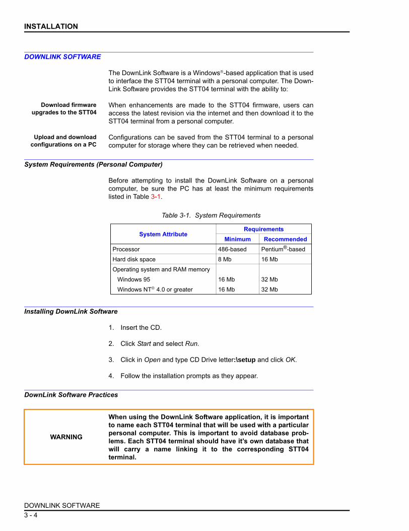
DOWNLINK SOFTWARE
The DownLink Software is a Windows-based application that is usedto interface the STT04 terminal with a personal computer. The Down-Link Software provides the STT04 terminal with the ability to:
Download firmwareupgrades to the STT04
When enhancements are made to the STT04 firmware, users canaccess the latest revision via the internet and then download it to theSTT04 terminal from a personal computer.
Upload and downloadconfigurations on a PC
Configurations can be saved from the STT04 terminal to a personalcomputer for storage where they can be retrieved when needed.
System Requirements (Personal Computer)
Before attempting to install the DownLink Software on a personalcomputer, be sure the PC has at least the minimum requirementslisted in Table 3-1.
Installing DownLink Software
1. Insert the CD.
2. Click Start and select Run.
3. Click in Open and type CD Drive letter:\setup and click OK.
4. Follow the installation prompts as they appear.
DownLink Software Practices
Table 3-1. System Requirements
System AttributeRequirements
Minimum RecommendedProcessor 486-based Pentium®-basedHard disk space 8 Mb 16 MbOperating system and RAM memory
Windows 95 16 Mb 32 MbWindows NT 4.0 or greater 16 Mb 32 Mb
WARNING
When using the DownLink Software application, it is importantto name each STT04 terminal that will be used with a particularpersonal computer. This is important to avoid database prob-lems. Each STT04 terminal should have its own database thatwill carry a name linking it to the corresponding STT04terminal.
DOWNLINK SOFTWARE3 - 4

SECTION 4 - OPERATING PROCEDURES
INTRODUCTION
This section covers the functions of the various keys on the STT04Smart Transmitter Terminal. Step-by-step procedures illustrate eachfunction.
This section covers:
• Keypad function table.• Send configurations.1• Get configurations.1• View configurations.1• Erase configurations.1• Change working configurations.1• Operational functions:
Special feature.Monitor.Status.Rerange.Options.
NOTE: 1. These functions apply to all transmitters. The proceduresare not duplicated for each transmitter type. The 600T HART trans-mitter is used in the example procedures.
The creation and modification of configurations and calibrations aredevice specific and therefore are covered in the device specificappendices of this instruction.
HOW TO USE THE PROCEDURE TABLES
Procedures for each of the functions are presented in tables havingthree columns: Key, Display, and Comments. The tables read fromleft to right. When the key shown is pressed, the screen showndirectly to the right in the display column appears on the terminalscreen. The comment pertains to that screen. Use the proceduretables to step through the functions.
OPERATOR/INTERFACE CONTROLS
Table 4-1 provides a description of functions for the keys on theSTT04 terminal.
NOTE: The configure, view, select device and options keys functionwithout a field device connected to the STT04 terminal. The otherfunctions are locked out until a field device is connected to theterminal.
INTRODUCTION 4 - 1

OPERATING PROCEDURES
Table 4-1. Keypad Functions
Key FunctionPowers the unit up and displays the STT04 firmware revision level.
Turns power off. Stored configurations remain in internal memory. The terminal will shut itself off after 15 minutes of idle operation.
Scrolls through menus and selects functions.
Inputs values into the terminal. Includes digits 0 through 9, ASCII characters A through Z, signs, and punctuation.
Completes an input or a selection.
1. Inputs a new configuration into the STT04 internal memory.2. Modifies an existing configuration.3. Erases an existing configuration from the terminal memory.
Retrieves, views and optionally saves the configuration of the selected field device.
Sends a configuration from the STT04 terminal to a selected field device.
Steps through various calibration procedures (dependent on the selected field device).
Monitors primary input or output, secondary output, ambient temperature of the selected field device, and other variables.
Displays field device status based on results of continuous self-diagnostics.
1. Changes engineering units.2. Sets lower and upper range values of primary and secondary units.3. Changes the output dampening.
O N
O FF
+ : / < > *
0% & G H I
9
E N TE R
C O N F IG
G E T C O N F IG
S EN D C O N FIG
C A LI- B R ATE
M O N ITO R
S TATU S
R E - R A N G E
OPERATOR/INTERFACE CONTROLS4 - 2

OPERATING PROCEDURES
INITIAL START-UP
The sequence of screens described will appear when the STT04 ter-minal is powered up for the first time and is not connected to a fielddevice, or when a configuration is created and stored in the terminal.
NOTE: The terminal (if not configuring or calibrating) will automati-cally shut itself off after approximately 15 minutes without operatorinteraction.
1. Sets output to a fixed value.2. Cancels a fixed output.3. Sets up LCD - select display units to be displayed on the field device LCD.4. Changes device configuration to the standard configuration (PTS only).
NOTE: For special feature functions refer to the appropriate Appendix.Escapes the current function and returns the display to the READY condition.
Selects and changes working configurations and field devices (if connected).
Steps through the selections of the working configuration. Views a configura-tion, but does not allow modifications to be made.
1. Sets the language of the display screens.2. Sets the communication format.3. Displays the amount of charge left on the battery pack.4. Displays the STT04 name.Returns to a previous screen during configuration, calibration, rerange, etc.
Table 4-1. Keypad Functions (continued)
Key Function
S PE C IA LFE ATU R E
C LE AR
S EL E C T D E VIC E
V IEW
O P T IO N S
B AC K
Key Display CommentsDisplays the firmware revision of the STT04 terminal.
STT04 terminal prompts for a communication format. Select a communication format using the up or down key. After selecting communications, the terminal scans for devices of the selected format. Select the correct communication format.
O N
ABBSTT04
REVISION nn.n
E N TE R
COMMUNICATION FORMAT
→ ABB FSKHART
INITIAL START-UP 4 - 3

OPERATING PROCEDURES
SELECTING CHARACTERS FROM THE KEYPAD
Character entry into the STT04 terminal is done using the numerickeypad. The following example details how character entry is per-formed.
STT04 terminal attempting to communicate with a field device. If the terminal is connected to a field device, the READY screen appears. If the terminal is not connected to a device, it searches for configura-tions that have been stored.
Appears only if field devices are not connected. The STT04 terminal searches for configurations in its internal memory. If configurations are present, a list of ID tag names appears.
Only appears if HART is selected for communication format and no analog field devices are connected.
Choose YES to poll for digital devices.
A configuration can be created. Refer to the appendi-ces at the back of this instruction for configuration procedures for all supported devices.
Key Display Comments
E N TE R
SCANNING FORSMART
FIELD DEVICES
NO SMART FIELD DEVICERESPONDING
E N TE R
NO ANALOG DEV FOUND.POLL FOR DIGTAL DEV?
→ NOYES
CHOOSE A TAGREADY
Key Display CommentsSelect NEW to create a configuration.
Select HART.
Select 600T.
C O N F IG
CONFIGURATION→ NEW
MODIFYERASE
E N TE R
DEVICE TYPE
→ HART
E N TE R
TRANSMITTER TYPE→ PTS EQS
BCN EQNAVS TBN480
SELECTING CHARACTERS FROM THE KEYPAD4 - 4

OPERATING PROCEDURES
For this example, use the configuration ID tag name of W1.
Press the 2 key and a 2 appears in the first character place.
Press the 2 key again and the letter V appears in the first character place.
Press the 2 key again and the letter W appears in the first character place.
The cursor is in the second character position.
Press the 1 key and the number 1 appears in the second character position.
Press and abort this configuration.
Key Display Comments
E N TE R
STT04 CONFIGURATION[_ ]
←PREVIOUS NEXT→
V W X
2
STT04 CONFIGURATION[ 2 ]
←PREVIOUS NEXT→
V W X
2
STT04 CONFIGURATION[V ]
←PREVIOUS NEXT→
V W X
2
STT04 CONFIGURATION[ W ]
←PREVIOUS NEXT→
STT04 CONFIGURATION[ W_ ]
←PREVIOUS NEXT→
1S T U
STT04 CONFIGURATION[ W1 ]
←PREVIOUS NEXT→
E N TE R
SELECT MODE:→ ANALOG
DIGITAL
CLEAR
SELECTING CHARACTERS FROM THE KEYPAD 4 - 5

OPERATING PROCEDURES
VIEW AND SELECT CONFIGURATION
Use the view function key to:
• Review the parameters of a configuration.
• Select a new working configuration.
Key Display CommentsThe STT04 terminal is ready for operation. The ID TAGNAME in the left corner is either the configura-tion name or device name.
Displays configurations. Use the arrow keys to select the desired configuration. The brackets indicate the selected configuration.
NOTE: To more quickly scroll through configurations (three at a time) press the left arrow key to scroll down or the right arrow key to scroll up.
.
.
.
Press continuously while reviewing the parameters, until the READY screen appears.
NOTE: To select a configuration without reviewing all the parameters, press after selecting the configuration.
The new working configuration name appears in the upper left portion of the screen.
ID TAGNAME
READY
V IEW
STT04 CONFIGURATION2. [CONFIGNAME2]3. CONFIGNAME34. CONFIGNAME4
E N TE R
ENTER
CLEAR
E N TE R
ID TAGNAME2
READY
VIEW AND SELECT CONFIGURATION4 - 6

OPERATING PROCEDURES
SEND CONFIGURATION
Use the send configuration function key to send a configuration fromthe terminal to a connected device.
Key Display CommentsA complete list of configurations display (three per screen). To select from the existing configurations, use the arrow keys to scroll through the list.
NOTE: To more quickly scroll through configurations (three at a time) press the left arrow key to scroll down or the right arrow key to scroll up.Displays the ID tag name of the selected transmitter.
Configuration was sent successfully.
S EN D C O N FIG
STT04 CONFIGURATION1. [CONFIGNAME]2. CONFIGNAME23. CONFIGNAME3
E N TE R
SELECT TRANSMITTER[nnnnnnnnnnnnnnnnnn]
E N TE R
SENDING CONFIGURATION
ID TAGNAME
READY
SEND CONFIGURATION 4 - 7

OPERATING PROCEDURES
GET CONFIGURATION
Use the get configuration function key to view and save the configura-tion of a connected field device. Get configuration requires that theSTT04 terminal be connected to a device.
NOTE: This procedure is similar for all device types. It is intended asa general guide for this function. Variances occur based on devicetype.
Key Display CommentsThe name within the brackets is the working configuration.
The option to save the configuration in the STT04 terminal internal memory is presented. When the configuration is stored, exit the function by pressing
.
NOTE: A maximum of 100 configurations can be stored in the STT04 terminal.
The device ID tag name and manufacturer is dis-played for HART transmitters only.
Displays the 14 character ID tag name of the con-nected device. The TYPE field displays the device type. If ANALOG mode, the CHANNEL field will not show.
Indicator points to the configured output type.
NOTE: Use to return to any screen during configuration.
Configured output action is displayed.
G E T C O N F IG
SELECTED CONFIGURATION
[nnnnnnnnnnnnnnnnnn]
E N TE R
STORE THISCONFIGURATION?
NO→ YES CLEAR
E N TE R
CONFIG ID TAGNAMEDEVICE MFR: ABB
E N TE R
CONFIG ID TAGNAMETYPE: 600T
MODE: DIGITALCHANNEL: 2
E N TE R
OUTPUT TYPE:LINEAR
→ SQUARE ROOT3/2 FLOW MODE
BACK
E N TE R
OUTPUT ACTION:→ NORMAL
REVERSE
GET CONFIGURATION4 - 8

OPERATING PROCEDURES
Damping value is displayed to the nearest hundredth of a second.
Lower and upper range values are displayed.
Indicator points to the configured initialization mode.
Indicator points to the configured fail mode.
Secondary upper and lower range values are displayed to the nearest hundredth.
Only applies if interfacing a PTS, PTH, EQS or EBTH transmitter. The upper and lower range temperature alarm values are shown as configured.
This display appears when configuring HART trans-mitters only. A message of up to 32 characters can be entered.
This display appears when configuring HART trans-mitters only. A descriptor of up to 16 characters can be entered.
Key Display Comments
E N TE R
DAMPING(0 - 32 SEC)
6.00 SEC
E N TE R
LOWER RANGE VAL.nn.nn UNITS
UPPER RANGE VAL.nn.nn UNITS
E N TE R
INITIALIZE MODE:→ LOW
HIGH
E N TE R
FAIL MODE:→ LOW
HIGHLAST
E N TE R
SECONDARY L. R.nn.nn UNITS
SECONDARY U. R.nn.nn UNITS
E N TE R
LOWER TEMP ALARM-50.00°C
UPPER TEMP ALARM120.00°C
E N TE R
MESSAGE:
←PREVIOUS NEXT→
E N TE R
DESCRIPTOR:
←PREVIOUS NEXT→
GET CONFIGURATION 4 - 9

OPERATING PROCEDURES
ERASE CONFIGURATION
Use this function to erase a configuration from the STT04 terminalmemory.
NOTE: This procedure is identical for all device types.
This display appears when configuring HART trans-mitters only. Two digits can be entered for the day, month and year.
Configuration ID tag name just configured will be in the upper left corner if the configuration was saved. This becomes the working configuration.
Key Display Comments
E N TE R
DATE:DAY: nnMONTH: nnYEAR: nn
E N TE R
ID TAGNAMEREADY
Key Display CommentsSelect ERASE.
Displays the stored configurations. Use the scroll keys to select a stored configuration to view. The ID tag name that is bracketed indicates it is selected for deletion.
NOTE: To more quickly scroll through configurations (three at a time) press the left arrow key to scroll down or the right arrow key to scroll up.To erase the selected configuration, use the down arrow key to move the pointer to YES, then press
.
NOTE: To return to the READY screen without eras-ing a configuration, press .
C O N F IG
CONFIGURATIONNEWMODIFY
→ ERASE
E N TE R
STT04 CONFIGURATION1. FT1012. FT1033. LT 106
E N TE R
ERASE ID TAGNAME→ NO
YESENTER
CLEAR
ERASE CONFIGURATION4 - 10

OPERATING PROCEDURES
To completely erase the smart terminal internal memory of storedconfigurations:
1. Turn the STT04 terminal OFF.
2. Press and hold the minus ( - ) and enter keys down simulta-neously.
3. Turn the STT04 terminal ON. A confirmation message appearsconfirming the deletion:
* ERASING CONFIGS *- COMPLETE -
4. Turn the STT04 OFF and then ON again to access a READYscreen.
OPERATIONAL FUNCTIONS
The operational functions of the STT04 terminal apply to all transmit-ter types. The following functions are covered in this section:
• Special feature key.• Monitor key.• Status key.• Rerange.• Option key.
NOTE: A series of n s in the display portion of the function proce-dures indicate that an alphanumeric character can be displayed orentered in that position.
Key Display Comments
ID TAGNAME
READY
OPERATIONAL FUNCTIONS 4 - 11

OPERATING PROCEDURES
Special Feature Key
The special feature key has different functions for each transmitter.Reference the specific product instruction for special feature informa-tion. An example of the PTS transmitter is explained in this section.
Use the special feature key to:
• Fix output and cancel fix output.• Set up the LCD.• Access the standard configuration.
NOTES:1. A device must be connected to the terminal in order to usethese functions.
2. The special feature functions for positioner vary from the stan-dard functions. For details, refer to Appendix A.
FIX OUTPUT/CANCEL FIX OUTPUT
The fix output function allows the output to be held at a specific (fix)percentage value of output. This can be used for diagnostic purposes.The output of the field device does not change until cancel fix outputis performed. The following procedure steps through the fix and can-cel fix output procedure.
Key Display CommentsSelect FIX OUTPUT.If CANCEL FIX OUTPUT is selected, press and the READY screen appears.
Use the number key pad to input the desired fix out-put value.
The output remains at a fixed value until CANCEL FIX OUT is selected.
S PE C IA LFE ATU R E
→ FIX OUTPUTCANCEL FIX OUTLCD SETUPSTANDARD CONFIGRST CFG CHANGED FLG
ENTER
E N TE R
FIX OUTPUT TO:nnn.nn%
E N TE R
ID TAGNAME
READY
OPERATIONAL FUNCTIONS4 - 12

OPERATING PROCEDURES
LCD SETUP
This function allows the device output to be displayed in secondaryunits, primary units, or percentage of output on the local display of thedevice. In addition, transducer or junction temperature values and IDtag name may be available. Check appropriate Appendix for parame-ters available.
Key Display CommentsUse the arrow keys to select LCD SETUP.
NOTE: Menu selections will vary depending on device type.
Specify the LCD display variable. The selected parameters will be displayed locally on the device LCD.
NOTE: An additional selection for LCD setup can exist called ID TAG. This option allows non-HART devices to display the ID tag name locally on the device LCD.
S PE C IA LFE ATU R E
FIX OUTPUTCANCEL FIX OUT
→ LCD SETUPSTANDARD CONFGRST CFG CHANGED FLG
E N TE R
→ SECONDARY E. U.PRIMARY E. U.% OUTPUTCELL TEMP.
ID TAGNAME
READY
OPERATIONAL FUNCTIONS 4 - 13

OPERATING PROCEDURES
STANDARD CONFIGURATION
This function allows the device to be configured using the original fac-tory configuration.
Key Display CommentsUse the arrow keys to select STANDARD CONFG.
Press to reset the transmitter name in brack-ets back to the standard configuration, or press
to abort the reset function.
Select YES.
Use to select a tag as the working configuration.
S PE C IA LFE ATU R E
FIX OUTPUTCANCEL FIX OUTLCD SETUP
→ STANDARD CONFGRST CFG CHANGED FLG
E N TE R
RESET TO STD.CONFIGURATION?[ ]
PRESS ENTER
ENTER
CLEAR
E N TE R
OUTPUT WILL BEAFFECTED! PROCEED?
NO→ YES
E N TE R
SENDING STANDARD CONFIG
CHOOSE A TAG
READY
SELECT DEVICE
OPERATIONAL FUNCTIONS4 - 14

OPERATING PROCEDURES
RESET CONFIGURATION CHANGE FLAG
This function resets the configuration change flag on HART devices.When a device configuration parameter changes on a PTH or EBTH,a change flag is set. When a change flag is set and a device status isretrieved, the message: CONFIG CHANGED appears. When reset,the status of the device is OK.
Key Display CommentsUse the arrow keys to select RST CFG CHANGED FLG. Clears the configuration changed flag of the HART device.
S PE C IA LFE ATU R E
FIX OUTPUTCANCEL FIX OUTLCD SETUPSTANDARD CONFG
→ RST CFG CHANGED FLG
E N TE R
CHOOSE A TAG
READY
OPERATIONAL FUNCTIONS 4 - 15

OPERATING PROCEDURES
Monitor Key Functions
The monitor key functions slightly vary, based on the device. Anexample of the PTS transmitter is explained in this section.
Use the monitor function key to monitor:
• Primary output.• Primary input.• Secondary engineering units.• Temperature of cell.
NOTES:1. For details about monitor key functions, refer to Monitor KeyFunctions in Appendix A.
2. A device must be connected to the terminal in order to use themonitor key functions.
MONITOR PRIMARY OUTPUT
This function allows output monitoring of the field device. The outputis displayed in percentage of the calibrated range.
Key Display CommentsSelect PRIMARY OUTPUT.
The output is displayed in percentage of the cali-brated range. The display is updated every second. Press to exit the monitor input function.
M O N ITO R
→ PRIMARY OUTPUTPRIMARY INPUTSECONDARY UNITSTEMPERATURE
E N TE R
ID TAGNAMEPRIMARY OUTPUT:
nnn.nn%GOOD STATUS
CLEAR
C LE AR
ID TAGNAME
READY
OPERATIONAL FUNCTIONS4 - 16
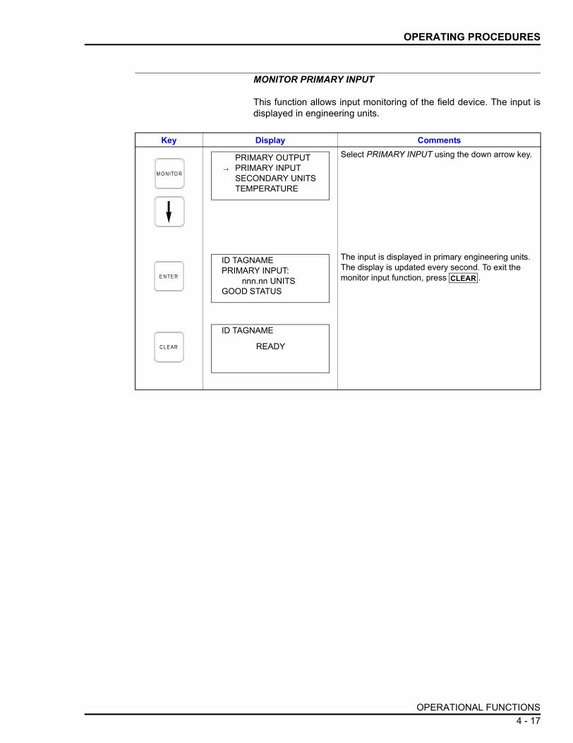
OPERATING PROCEDURES
MONITOR PRIMARY INPUT
This function allows input monitoring of the field device. The input isdisplayed in engineering units.
Key Display CommentsSelect PRIMARY INPUT using the down arrow key.
The input is displayed in primary engineering units. The display is updated every second. To exit the monitor input function, press .
M O N ITO R
PRIMARY OUTPUT→ PRIMARY INPUT
SECONDARY UNITSTEMPERATURE
E N TE R
ID TAGNAMEPRIMARY INPUT:
nnn.nn UNITSGOOD STATUS
CLEAR
C LE AR
ID TAGNAME
READY
OPERATIONAL FUNCTIONS 4 - 17

OPERATING PROCEDURES
MONITOR SECONDARY UNITS OUTPUT
This function allows the output to be viewed in secondary units.
TEMPERATURE FUNCTION
Displays the temperature of the transducer or reference temperaturein degrees Celsius.
Key Display CommentsSelect SECONDARY UNITS using the down arrow key.
The output is displayed in secondary units.
M O N ITO R
PRIMARY OUTPUTPRIMARY INPUT
→ SECONDARY UNITSTEMPERATURE
E N TE R
ID TAGNAMESECONDARY UNITS
nnn.nn UNITSGOOD STATUS
C LE AR
ID TAGNAME
READY
Key Display CommentsSelect TEMPERATURE using the down arrow key.
M O N ITO R
PRIMARY OUTPUTPRIMARY INPUTSECONDARY UNITS
→ TEMPERATURE
OPERATIONAL FUNCTIONS4 - 18

OPERATING PROCEDURES
Status Check
The following is a procedure for checking the status of a device basedon the results of the continual self diagnostics. The diagnosticsinclude monitoring the transducer, transducer temperature, transmit-ter ambient temperature, input circuits, processor EEPROM, nonvola-tile memory, and reference voltages.
NOTE: When status key is pressed, the problem holding the highestpriority (based on an internal priority structure) is displayed for ABBdigital FSK devices. Any other problem that may exist cannot beviewed until the problem with the highest priority is corrected. HARTdevices show the top eight (priority) messages in a single scrollablescreen. If an error message is displayed, refer to Section 5 for trou-bleshooting information.
Rerange Key Function
Use the rerange key to change the:
• Upper and lower range values of the field device.• Upper and lower temperature alarm values of the field device
(where available).• Upper and lower secondary units.• Damping time.
NOTE: Field device output is based on the values entered in thisprocedure. The terminal will not reject invalid ranges; therefore, it isimperative that the range limits specified for the device are known.Refer to the applicable product instruction for range limits.
The temperature of the transducer or reference tem-perature is displayed.
Key Display Comments
E N TE R
ID TAGNAMETEMPERATURE:
nnn.nn°CGOOD STATUS
C LE AR
ID TAGNAME
READY
Key Display CommentsTest results were successful, no problems to report. If the field device has diagnosed a problem in any of the areas mentioned above, refer to Section 5 of this product instruction.
S TATU S
FIELD DEVICE O.K.
OPERATIONAL FUNCTIONS 4 - 19

OPERATING PROCEDURES
Key Display CommentsThis operation will cause a change in output not cor-responding to the input. Be sure the control loop is in manual.
Use the down arrow key to select YES.
Engineering units displayed are those selected dur-ing configuration or calibration. The positioner sends the ranges to the positioner after specifying the upper and lower range values.
Input the desired value using the numeric keypad. Press . Repeat for upper range value.
Lower and upper temperature alarms apply only when reranging PTS, PTH, EQS or EBTH transmit-ter.
-50.00° and 120.00°C are the default values. Enter different values or accept the default values by pressing .Input the desired value using the numeric keypad. Press .
The rerange key will update the field device configu-ration, not the STT04 terminal internal configuration. To update the internal STT04 terminal configuration, use the get configuration key to view and save the configuration to the STT04 terminal.
R E - R A N G E
OUTPUT WILL BEAFFECTED! PROCEED?
NO→ YES
E N TE R
LOWER RANGE VAL_ nn.nn iH20
UPPER RANGE VALnn.nn iH20
E N TE R
SECONDARY L. R._ nn.nn UNITS
SECONDARY U. R.nn.nn UNITS
ENTER
E N TE R
LOWER TEMP ALARM-50.00°C
UPPER TEMP ALARM120.00°C
ENTER
E N TE R
DAMPING(0-32 SEC)
nn.nn SEC
ENTER
E N TE R
SENDING RANGES
ID TAGNAME
READY
OPERATIONAL FUNCTIONS4 - 20

OPERATING PROCEDURES
Options Key Functions
Use the options function key to:
• Set the language of the display screens.• Change communications format.• Check the battery charge. • View the STT04 name.• View STT04 firmware and boot code revision numbers.
LANGUAGE
Use this function to select the language of the STT04 displayscreens.
Key Display CommentsSelect LANGUAGE.
Select the language using the up and down arrow keys. The last language selection made is main-tained for the next power up.
The STT04 terminal will display screens in the selected language.
O P TIO N S
STT04 OPTIONS:→ LANGUAGE
COMMUN. FORMATBATTERY
E N TE R
→ ENGLISHFRANCAISDEUTSCHESPANOL
E N TE R
ID TAGNAME
READY
OPERATIONAL FUNCTIONS 4 - 21

OPERATING PROCEDURES
COMMUNICATION FORMAT
Use this function to change the communications format of the STT04terminal.
BATTERY
Use this function to see the approximate amount of charge left in thebatteries.
Key Display CommentsSelect COMMUN. FORMAT.
Select the desired communication format using the up and down arrow keys. After selecting communica-tions, the terminal scans for devices of the selected format. Select the correct communication format.
O P TIO N S
STT04 OPTIONS:LANGUAGE
→ COMMUN. FORMATBATTERY
E N TE R
COMMUNICATION FORMAT:
→ ABB FSKHART
E N TE R
ID TAGNAME
READY
Key Display CommentsSelect BATTERY.
O P TIO N S
STT04 OPTIONS:LANGUAGECOMMUN. FORMAT
→ BATTERY
OPERATIONAL FUNCTIONS4 - 22

OPERATING PROCEDURES
STT04 NAME
Use this function to view the name of the STT04 terminal as specifiedin the DownLink software program.
Shows an approximation of the remaining charge on the batteries as a percentage. Recharge the battery when the available charge is below 25 percent.
Key Display Comments
E N TE R
AVAILABLE BATTERY CHARGE: nn %
E N TE R
ID TAGNAME
READY
Key Display CommentsSelect STT04 NAME.
Shows the name of the STT04 terminal as specified in the DownLink software application.
O P TIO N S
STT04 OPTIONS:COMMUN. FORMATBATTERY
→ STT04 NAME
E N TE R
STT04 NAME
ABB STT04
E N TE R
ID TAGNAME
READY
OPERATIONAL FUNCTIONS 4 - 23

OPERATING PROCEDURES
STT04 REVISION
Use this function to view the firmware and boot code revisions of theSTT04 terminal.
Key Display CommentsSelect STT04 REV.
Shows the firmware and boot code revisions of the STT04 terminal.
O P TIO N S
STT04 OPTIONS:BATTERYSTT04 NAME
→ STT04 REV
E N TE RFIRMWARE: nn.n
BOOTCODE: nn.n
E N TE R
ID TAGNAME
READY
OPERATIONAL FUNCTIONS4 - 24

OPERATING PROCEDURES
UPLOADING AND DOWNLOADING CONFIGURATIONS
STT04 terminal provides configuration storage flexibility. Configura-tions can be created and stored on the STT04 terminal or storedremotely on a personal computer. To remotely store configurations,the DownLink software is required. DownLink software is shippedwith the STT04 (A1.1 or greater) terminal.
NOTE: If you do not have the DownLink software application, con-tact the nearest ABB sales office for availability.
Use the following procedure to upload or download configurations:
1. Connect the female end of the RS-232-C (customer supplied)cable to a vacant RS-232-C port (serial port) on the personal com-puter.
2. Connect the male end of the RS-232-C cable to the STT04 termi-nal.
3. If the personal computer is not on, turn it on and allow it to boot.
4. Turn off the STT04 terminal.
5. Put the STT04 terminal into the remote mode by pressing one ofthe following key sequences based on the language of the STT04 ter-minal (Table 4-2).
The STT04 terminal screen displays the following:
NOTE: The first line that reads ABB STT04 is the default STT04name. A unique STT04 name should be specified using the Down-Link software application. In which case, the specified name wouldappear in place of ABB STT04.
6. Click Start on the personal computer and open the ABB-STT04program group.
Table 4-2. Languages
Language STT04 Key SequenceEnglish Hold down and and press .
French Hold down and and press .
Spanish Hold down and and press .
German Hold down and and press .
1 ↑ On
2 ↑ On
3 ↑ On
4 ↑ On
ABB STT04
IN
REMOTE MODE
UPLOADING AND DOWNLOADING CONFIGURATIONS 4 - 25

OPERATING PROCEDURES
7. Double click the STT04 DownLink Software icon.
Upload form STT04 to PC a. Click Transfer Configuration and select Upload from STT04.
b. Select a configuration and click Ok.
Download to STT04 fromPC
a. Click Transfer Configuration and select Download to STT04.
b. Select a configuration and click Ok.
8. When the download process is complete, turn off the STT04 ter-minal and disconnect the RS-232-C cable from the STT04 and PC.
UPLOADING AND DOWNLOADING CONFIGURATIONS4 - 26

SECTION 5 - TROUBLESHOOTING
INTRODUCTION
This section contains all of the possible error messages that can dis-play on the STT04 terminal.
The troubleshooting tables have four columns:
• The Message column lists the errors (alphabetically) exactly asthey appear on the terminal.
• The Affected Device column lists the device type the error canaffect. Some probable cause and corrective action may varydepending on the affected device.
• The Probable Cause column provides a brief explanation of thecause of the error.
• The Corrective Action column lists corrective actions to take foreach error.
ERROR MESSAGES
When the Status key is pressed, if a problem exits an error messageis displayed. The errors are based on an internal priority structurewhere the most critical error takes priority over less critical errors.ABB digital FSK devices only show one error message at a time. Ifmore than one error message is present, the one holding the highestpriority must be corrected before other lower priority messages canbe viewed. HART device error messages only occupy one line on theLCD, therefore more than one error message can be viewed at onetime. Table 5-1 lists the HART error messages in alphabetical order.Table 5-2 lists ABB FSK device specific and common STT error mes-sages in alphabetical order.
NOTE: The most common cause of field problems occur due to wir-ing errors or DCS system configuration errors. Check these areasfirst before proceeding.
INTRODUCTION 5 - 1

TROUBLESHOOTING
Table 5-1. STT04 Error Messages for HART Devices
Message Affected Device Probable Cause Corrective Action
A/D HIGH REF FAIL PTH EBTH
Reference problem on circuit board.
Replace amplifier assembly. If problem still exists, replace cell and characterization board. Refer to the repair/replacement sec-tion of the appropriate instruction.
A/D LOW REF FAIL PTH EBTH
Reference problem on circuit board.
Replace amplifier assembly. If problem still exists, replace cell and characterization board. Refer to the repair/replacement sec-tion of the appropriate instruction.
AMBIENT TEMP HIGH EBTH Temperature inside the electronics housing exceeds 85°C (185°F)
Remove the source of temperature extreme.
AMBIENT TEMP LOW EBTH Temperature inside the electronics housing is less than -50°C (-58°F)
AO SATURATED All HART Process variable is greater than +103.13% or less than -1.25% of its range and the analog out-put cannot show changes in its process.
Check for proper sensor connection to the transmitter.Check that the transmitter range is appro-priate for the application.Perform a D/A adjustment.
CAL OFFSET WARNING
TB82 Large positive sensor off-set (>180 mV) or large negative sensor offset (<-180 mV)
Clean sensor and perform buffer and pro-cess calibration.Inspect sensor and calibrating for shorts. Remove all potential shorts to ground, con-duit or metals.
CAL OFFSET WARNING (continued)
TB82 Large positive sensor off-set (>180 mV) or large negative sensor offset (<-180 mV)
If sensor is functioning properly, order spare sensor to replace existing sensor with spare when transmitter does not accept calibra-tion values.
CALIBRATION FAILED HIGH/LOW
EBTH The applied calibration signal is higher/lower than allowable factory limits.
Calibrate the transmitter and verify the sup-plied signals are within transmitter limits.
CALIBRATION REQUIRED
PTH EBTH
Field device needs to be calibrated.
Calibrate the field device. Refer to the cali-bration section of the appropriate product instruction.
CELL EEPROM FAILURE
PTH Memory problem. Remove power from the field device and reapply. If problem persists replace the amplifier assembly. Refer to repair/replace-ment section of the field device product instruction.
CELL TEMP OVR/UNDR ALARM
PTH Cell temperature over/under user alarm limit.
Correct temperature problem.Change alarm value. Refer to configuration procedures for PTH PRESSURE TRANS-MITTER in Appendix D.
ERROR MESSAGES5 - 2

TROUBLESHOOTING
CELL TEMP OVR/UNDR LMT
PTH Cell temperature input is over/under factory speci-fied limits.
Remove the source of temperature extreme.
COLD START All Reset or self-test of the field device occurred or power was removed and reapplied to the device.
No corrective action required. Notification only.
CONFIG CHANGED All HART Parameters of configura-tion changed
Perform RESET CONFIG.
DYNMC TEMP MST FAIL
PTH Dynamic temperature input exceeded limits set at factory.
NOTE: The temperature of thehigh side of the cell with respectto the low side of a PTH.
Output may no longer be accurate. Remove source of temperature shift.
ELEC TEMP OVR/UNDR RANG
PTH Electronics temperature is outside the factory specified limit.
Remove the source of the temperature extreme.
ELECT TEMP MST FAIL
PTH Hardware failure of on-board temperature sensor.
Replace amplifier assembly. Refer to repair/replacement section of the appropriate product instruction.
FIELD DEVICE IN MULTIDROP MODE
All HART Device is in digital mode. Command cannot be performed. Configure device for analog mode (point-to-point).
FIXED OUTPUT MODE
All HART STT terminal turned off while the 4 to 20 mA out-put was being calibrated.
Power down the transmitter and power up the transmitter.
Transmitter cannot exe-cute command because of fix output.
Take transmitter out of fix output. Refer to FIX OUTPUT/CANCEL FIX OUTPUT in Section 4.
INPUT OVER RANGE PTH EBTH
Input out of range. Reduce process input, or configure proper limits. To verify proper limits use
to view the limits.Input greater than cell specification.
Reduce input pressure.
INPUT UNDER RANGE
PTH EBTH
Input exceeds the cell specification.
Increase input pressure.
Input value too low. Increase process input, or configure proper limits. To verify proper limits use
to view the limits. MAIN EEPROM FAILURE
PTH EBTH
Memory problem. Remove power from the field device and reapply. If problem persists replace the amplifier assembly. Refer to repair/replace-ment section of the appropriate product instruction.
Table 5-1. STT04 Error Messages for HART Devices (continued)
Message Affected Device Probable Cause Corrective Action
GET CONFIG
GET CONFIG
ERROR MESSAGES 5 - 3

TROUBLESHOOTING
MORE STATUS AVAIL. All HART HART device has more status available, but is not understood by the STT because the device is not supported by the STT.
Contact ABB technical support.
NON-PV OUT OF LIMIT
All HART Process applied to the nonprimary variable is outside the operating lim-its of the field device.
Correct process input.
OPEN SENSOR EBTH Field device temperature transducer failure.
Replace the temperature transducer. (i.e., thermocouple, RTD).
Field device temperature transducer not con-nected.
Connect the proper transducer (i.e., thermocouple, RTD).
PV OUT OF LIMITS All HART Process applied to the transmitter is outside the transmitter limits.
Correct the process input.
RAM FAILURE PTH EBTH
Internal RAM failure. Replace electronics. Refer to the repair/replacement section of the appropriate product instruction.
REF JUNCTION FAILURE
EBTH Reference junction (CJC) failed.
Replace the amplifier assembly.
SHORTED SENSOR EBTH Temperature transducer failure.
Replace temperature transducer.
Field wiring shorted Find and correct the wiring problem.SPAN ZERO KEY ERROR
PTH Misoperation of EZ CAL option.
Try again.
Damaged EZ CAL option. Replace EZ CAL option. Refer to the repair/replacement of the appropriate PTS product instruction.
Damaged amplifier assembly.
Replace amplifier assembly. Refer to the repair/replacement section of the appropri-ate PTS product instruction.
TEMP OFFSET WARNING
TB82 High or low temperature offset
Verify sensor wiring connections and inspect cable for shorts. Remove all poten-tial shorts to ground, conduit or metals.Verify that sensor had 10 to 15 min. to accli-mate to temperature environment to which it was calibrated.Disconnect temperature compensator leads from transmitter and measure resistance.Replace sensor with spare when transmitter does not accept calibration values.
Table 5-1. STT04 Error Messages for HART Devices (continued)
Message Affected Device Probable Cause Corrective Action
ERROR MESSAGES5 - 4

TROUBLESHOOTING
TEMP SLOPE WARNING
TB82 High or low temperature slope
Verify sensor wiring connections and inspect cable for shorts. Remove all poten-tial shorts to ground, conduit or metals.Verify that sensor had 10 to 15 min. to accli-mate to temperature environment to which it was calibrated.Disconnect temperature compensator leads from transmitter and measure resistance.Replace sensor with spare when transmitter does not accept calibration values.
USER TEMP HI/LO ALARM
EBTH Cell temperature over/under user alarm limit.
Correct temperature problem.Change alarm value. Refer to configuration procedures for EBTH TEMPERATURE TRANSMITTER in Appendix B.
Table 5-2. STT04 Error Messages for ABB FSK Devices
Message Affected Device Probable Cause Corrective Action
CALIBRATIONREQUIRED
PTS Cell has not been calibrated with present amplifier assembly.
Calibrate the field device. Refer to the calibration section of the appropriate PTS pressure transmitter instruction.
EQS Field device needs to be calibrated.
Calibrate the field device. Refer to the calibration section of the appropriate EQS temperature transmitter instruction.
CANNOT SAVE,CONFIGURATION TOO LARGE
STT Transmitter type not sup-ported by STT terminal revision level.
Consult ABB to obtain latest STT terminal revision.
CELLCHARACTERIZATIONBOARDEEPROM FAILURE
PTS Damage to cell characterization board.
Turn the STT terminal off and then on. If error still exists, replace cell (refer to repair/ replacement section of the appro-priate product instruction for procedure).
CELLTEMPERATURE OVER USER ALARM
PTSEQS
Cell temperature over/under user alarm limit.
Correct temperature problem.Change alarm value. Refer to configura-tion procedures for EQS TEMPERA-TURE TRANSMITTER in Appendix C or PTS PRESSURE TRANSMITTER in Appendix E.
CELLTEMPERATUREUNDER USER ALARMCELL TEMPERATURE OVER LIMIT
PTS Cell temperature input is over/under factory speci-fied limits.
Remove the source of temperature extreme.
CELL TEMPERATURE UNDER LIMITCOMMAND ABORTED STT Cancel key pressed
before function was com-pleted.
Try function again.
COMMUNICATION ERROR
STT Noisy signal. Check terminal wiring and eliminate source of noise.
Table 5-1. STT04 Error Messages for HART Devices (continued)
Message Affected Device Probable Cause Corrective Action
ERROR MESSAGES 5 - 5

TROUBLESHOOTING
CONFIG TAGNAME ALREADY EXISTS
All FSK Attempted to copy a configuration to a car-tridge or field device where it already exists.
Erase old configuration before copying new one. Refer to OPERATING PROCE-DURES in Section 4.
DAMAGEDCELL OR CHARACTERIZATIONBOARD
PTS Characterization board or cell is damaged.
Replace amplifier assembly. Refer to repair/replacement section of the appro-priate product instruction.Replace cell/characterization board. Refer to repair/replacement section of the appropriate product instruction.
DEVIATIONALARM
AVS Deviation has been greater than the alarm setting for two minutes.
Check valve.Check PID tuning.
DEVICE IN WRITE PROTECT MODE
STT Device is write protected. Change mode of device before trying to configure or calibrate.
DYNAMICTEMPERATUREMEASUREMENTFAILURE
PTS Dynamic temperature input exceeded limits set at factory.
NOTE: The temperature of thehigh side of the cell with respect tothe low side of a PTS.
Output may no longer be accurate. Remove source of temperature shift.
ELECTRONICSTEMPERATUREMEASUREMENTFAILURE
EQSPTS
Hardware failure of on-board temperature sensor.
Replace amplifier assembly. Refer to repair/replacement section of the appro-priate product instruction.
ELECTRONICTEMPERATUREOUT OF RANGE
PTS Electronics temperature is outside the factory speci-fied limit.
Remove the source of the temperature extreme.
EMPTY PIPE XM/SM/XE
The flowmeter is empty. Allow process to fill flow tube.
ERROR! ATTEMPT TO CONFIGUREDUPLICATEADDRESS
All FSK Attempt was made to assign an analog mode transmitter an address on FBS module.
Be sure transmitter is in the correct mode (analog or digital). Use to verify mode. Refer to OPERATING PROCE-DURES in Section 4 for details.
Attempt was made to assign a digital mode transmitter to an occu-pied FBS address.
Assign transmitter to an unoccupied address or channel number of FBS module.
ERROR!DEVICE TYPEAND CONFIGURATIONNOT COMPATIBLE
All FSK The configuration type (i.e., PTS) does not match the device type (i.e., BCN).
Select a device that is compatible with the configuration.
FIELD DEVICE CAN'T EXECUTECOMMAND: COMMAND CONFLICT
BCNEQNTBN
Commands were sent by STT terminal in the wrong order. Verify IMFBS01 is off-line if STT terminal is in use.
Try command again.
Table 5-2. STT04 Error Messages for ABB FSK Devices (continued)
Message Affected Device Probable Cause Corrective Action
VIEW
ERROR MESSAGES5 - 6

TROUBLESHOOTING
FIELD DEVICECAN'T EXECUTECOMMAND:FBS ON-LINE
All FSK STT terminal cannot change any transmitter parameters while the field bus is active.
Transmitter must be brought off-line. This can be done from the MFC/MFP by tun-ing the function code.
NOTE: To bring transmitter off-line, the retainer canbe unplugged from the rack. Be aware that by doingthis, communication is lost for all other transmitters onthe bus. When the retainer is unplugged, there is a2-minute time out period until the STT terminal will beallowed to change parameters. After the 2-minute pe-riod, the transmitter allows the STT terminal access.
FIELD DEVICECAN'T EXECUTECOMMAND:HARDWARE PROB-LEM
BCNEQNTBN
Detected error in hardware.
Press to determine error and use this table for appropriate corrective action. If status is not more explicit, check electronics assembly of field device.
AVS Unspecified hardware failure
Service unit.
FIELD DEVICECAN'T EXECUTECOMMAND:INVALID COMMAND
All FSK Incorrect syntax. Wrong device type selected in the configuration. Refer to the appropriate device configuration appendix for details about device type.
Excessive line noise. Check line noise. Use an oscilloscope to determine if line noise is excessive.
STT terminal failure. Verify STT terminal is operational by using another STT terminal that is known to be operational.
FIELD DEVICECAN'T EXECUTECOMMAND:LOCKOUT ENGAGED
All FSK Unable to configure or cal-ibrate. Hardware lock active.
Refer to the device product instruction for details about the configuration lockout jumper.
FIELD DEVICECAN'T EXECUTE:DATA OUT OF RANGE
All FSK Transmitter sent data that is out of acceptable range.
Press to verify the parameters of the configuration and consult the appro-priate device instruction for correct parameters.
FIELD DEVICECONFIGURATIONDOES NOT MATCHSTT'S
All FSK Configuration of the trans-mitter does not exactly match the corresponding configuration in the STT terminal.
Rerange was executed without updating the STT terminal configuration. Perform GET CONFIG. Refer to GET CONFIGURATION in Section 4.
NOTE: The positioner will change the installed optionflags if they are incorrect in the transmitted configura-tion. This error will appear if the configuration is not re-loaded by the STT terminal.
FIELD DEVICEMAINELECTRONICSEEPROM FAILURE
BCNEQNTBN
Memory problem. Reconfigure and recalibrate the transmit-ter. Refer to the appropriate configuration and calibration sections in this instruction for the transmitter type.
EQSPTS
Memory problem. Remove power from the field device and reapply. If problem persists replace the amplifier assembly. Refer to repair/replacement section of the field device product instruction.
Table 5-2. STT04 Error Messages for ABB FSK Devices (continued)
Message Affected Device Probable Cause Corrective Action
STATUS
VIEW
ERROR MESSAGES 5 - 7

TROUBLESHOOTING
FIELD DEVICEEPROM CHECKSUM ERROR
AVSBCNEQNTBN
Abnormal power up occurred.
Remove power from the field device and reapply.
Program chip on micro-computer board is bad.
Replace microcomputer board. Refer to repair/replacement section of the appro-priate product instruction for procedures.
Configuration has been lost or corrupted.
Resend the configuration.
FIELD DEVICEINPUT OVER RANGE
AVSBCNEQNEQS
Input out of range. Reduce process input, or configure proper limits. To verify proper limits use
to view the limits.
PTS Input greater than cell specification.
Reduce input pressure.
FIELD DEVICEINPUT UNDER RANGE
PTS Input less than cell specification.
Increase input pressure.
AVSEQS
Input value too low. Increase process input, or configure proper limits. To verify proper limits use
to view the limits. FIELD DEVICEINTERNAL REFERENCE FAILURE
AVSBCNEQNEQS
XM/SM/XE
Reference problem on circuit board.
Check connections. Replace electronics assembly. Refer to repair/replacement section of the appropriate field device instruction.
PTS Reference problem on circuit board.
Replace amplifier assembly. If problem still exists, replace cell and characteriza-tion board. Refer to the repair/replace-ment section of the appropriate PTS instruction.
FIELD DEVICEMAIN INPUTFAILURE
BCNEQNTBN
Sensor failure. Check input board connections. Refer to repair/replacement section of the appro-priate product instruction.
Input board failure. Replace input board. Refer to repair/replacement section of the appropriate product instruction.
FIELD DEVICEMICROCOMPUTERHAS BAD EEPROM
BCNEQNTBN
Microcomputer cannot retain configuration and calibration data.
Replace the microcomputer board. Refer to repair/replacement section of the appropriate product instruction.
Table 5-2. STT04 Error Messages for ABB FSK Devices (continued)
Message Affected Device Probable Cause Corrective Action
GET CONFIG
GET CONFIG
ERROR MESSAGES5 - 8

TROUBLESHOOTING
FIELD DEVICENOT RESPONDING
All FSK Noise on field wiring. Turn off STT terminal. ID tags appear on screen. Select the ID tag of the transmit-ter or, select the one appearing within brackets if unsure of ID tag. Press
. Press . If message is still present, continue to the next corrective action.
STT terminal not connected properly.
Check STT terminal wiring connections. Refer to Figure 2-1 or 2-2 for correct wir-ing arrangements.
Short in communication wire.
Perform a continuity check to determine if a short exists.
Transmitter does not have a minimum amount of voltage across inputs.
Correct power problem. Refer to appro-priate product instruction for minimum supply voltage requirements.
Transmitter or STT termi-nal is defective.
If available, verify that the STT terminal is functional by interfacing another transmit-ter. Replace the STT terminal if not func-tional.If STT terminal is functional, replace field device electronics assembly. PTS: Replace amplifier assembly, refer to repair/replacement section of the appro-priate product instruction for replacement procedures.
FIELD DEVICENOT SUPPORTEDBY STT
All FSK Field device type not sup-ported by the release of STT terminal.
Contact an ABB sales office for upgrade information.
FIELD DEVICEOPEN SENSOR
EQS Field device temperature transducer failure.
Replace the temperature transducer. (i.e., thermocouple, RTD).
Field device temperature transducer not connected.
Connect the proper transducer (i.e., thermocouple, RTD).
FIELD DEVICEOUTPUT IS FIXEDOR IN ADJ. MODE
All FSK STT terminal turned off while the 4 to 20 mA out-put was being calibrated.
Power down the transmitter and power up the transmitter.
Transmitter cannot exe-cute command because of fix output.
Take transmitter out of fix output. Refer to FIX OUTPUT/CANCEL FIX OUTPUT in Section 4.
FIELD DEVICE RAM FAILURE
All FSK Internal RAM failure. Replace electronics. Refer to the repair/replacement section of the appropriate product instruction.
Table 5-2. STT04 Error Messages for ABB FSK Devices (continued)
Message Affected Device Probable Cause Corrective Action
ENTER STATUS
ERROR MESSAGES 5 - 9

TROUBLESHOOTING
FIELD DEVICETEMPERATUREABOVE LIMIT
- or -
FIELD DEVICETEMPERATUREBELOW LIMIT
BCNEQNEQSTBN
XM/SM/XE
Field device not calibrated properly, or transmitter is at a temperature above the performance specifi-cations. Message will not affect operation but could mean temperature perfor-mance is out of range.
Recalibrate the field device. Refer to the appropriate calibration section for the device type.
NOTE: Uncalibrated field devices may have this erroruntil calibrated.
PTS Local heat or cold source exceeds electronics specifications.
Eliminate or reduce temperature extreme of the electronics.
FIELD DEVICETEMPERATURESENSOR FAILURE
BCNEQN
On-board temperature sensor failure.
Replace input board. Refer to repair/replacement section of the appropriate product instruction.
HIGH PROCESS ALARM
XM/SM/XE
Process value over/under alarm limit.
Correct process problem.Change alarm value. Refer to CREATE/MODIFY CONFIGURATION in Appendix I.
INPUT APPLIEDINCORRECTLY,CALIBRATION FAILURE
BCNEQNEQSPTSTBN
Input signal not at speci-fied level.
Correct signal and recalibrate. Refer to the appropriate calibration section for details.
LOSS OF COIL EXCITATION
XM/SM/XE
Coil excitation has stopped.
Check wiring of excitation signal and ref-erence signal. If both are OK, call service.
LOW PROCESS ALARM
XM/SM/XE
Process value over/under alarm limit.
Correct process problem.Change alarm value. Refer to CREATE/MODIFY CONFIGURATION in Appendix I.
MAIN POWER WAS LOST
XM/SM/XE
Power was lost to device. Check for loose wiring.Restore totalizers to known values if lost.
NO SMART FIELD DEVICE CONFIGURATIONSPRESENT
STT No configuration exists in the STT terminal memory.
Create configurations. Refer to OPERAT-ING PROCEDURES in Section 4.
NO SMART FIELD DEVICE RESPONDING
STT STT terminal not connected to a device.
Check STT terminal lead connections. Verify proper field device wiring. Refer to the installation section of the appropriate product instruction.
OPTION NOT INSTALLED
XM/SM/XE
The current configuration is calling to use the empty pipe detector which requires and optional board.
Add empty pipe detector option, or turn empty pipe detection off in the configura-tion.
OUTPUT PRESSUREABOVE LIMIT
AVS Pressure on output port 01 or 02 is too high.
Check air pressure supply.
POSITION TRANSMITTER
AVS The position transmitter (transducer) has failed.
Refer to the repair/replacement section of the appropriate positioner product instruction.
Table 5-2. STT04 Error Messages for ABB FSK Devices (continued)
Message Affected Device Probable Cause Corrective Action
ERROR MESSAGES5 - 10

TROUBLESHOOTING
SHORTED SENSOR EBTH Temperature transducer failure.
Replace temperature transducer.
Field wiring shorted. Find and correct the wiring problem.SOURCE PRESSURE BELOW LIMIT
AVS Supply pressure is too low.
Check air pressure supply.
SPAN & ZERO KEYMISOPERATION
PTS Misoperation of EZ CAL option.
Try again.
Damaged EZ CAL option. Replace EZ CAL option. Refer to the repair/replacement of the appropriate PTS product instruction.
Damaged amplifier assembly.
Replace amplifier assembly. Refer to the repair/replacement section of the appro-priate PTS product instruction.
STT CONFIG WRITE ERROR
STT Error saving configuration. Save configuration again. If problem per-sists contact ABB technical support.
STT INTERNAL CONFIG STORAGE FULL
STT STT terminal memory is full.
Erase some configurations. Refer to OPERATING PROCEDURES in Section 4.
STT RECEIVECHECKSUM ERROR
STT Checksum from device was corrupted.
Try again or check data.
If message persists, verify that electronic noise on line is within specifications using an oscilloscope.
STT RECEIVE FAILURE
STT Reply from device was possibly corrupted.
Try again or check data.
If message persists, verify that electronic noise on line is within specifications using an oscilloscope.
SYSTEM ERROR STT Unexpected interrupt request on STT.
Turn STT off and on again. If error per-sists, upgrade the STT firmware.
TAG ID LENGTHNOT SUPPORTEDBY FIELD DEVICE
BCNEQN
Attempting to send an ID tag name that uses too many characters for the particular transmitter.
Change the ID tag name to 12 or less characters.
TEMP ALARM AVS The electronics tempera-ture has exceeded the product specification.
Remove the source of the temperature extreme.
TOTALIZER CHECKSUM ERROR
XM/SM/XE
Error in stored totalizer value.
Reset totalizer or preset totalizer to a known good value.
UNKNOWN ERROR All FSK Transmitter reported an error that was not under-stood by STT terminal.
Contact ABB technical support.
VALUE ENTEREDABOVE LIMIT
STT Value specified in the configuration is above the limit.
Refer to the appropriate product instruc-tion for the value limits.
VALUE ENTEREDBELOW LIMIT
STT Value specified in the con-figuration is below the limit.
Refer to the appropriate product instruc-tion for the value limits.
Table 5-2. STT04 Error Messages for ABB FSK Devices (continued)
Message Affected Device Probable Cause Corrective Action
ERROR MESSAGES 5 - 11

VALUES OUT OF ACCEPTABLE RANGE FOR FIELD DEVICE
All FSK Value specified in the con-figuration is below the limit.
Refer to the appropriate product instruc-tion for the value limits.Check 4 to 20 mA input.
VALVE STUCK Positioner Valve has not moved for over two minutes.
Check valve.Check 4 to 20 mA input.
OPTION NOT INSTALLED
XM/SM/XE
The current configuration is calling to use the empty pipe detector which requires an optional board.
Add empty pipe detector option, or turn empty pipe detection off in the configuration.
Table 5-2. STT04 Error Messages for ABB FSK Devices (continued)
Message Affected Device Probable Cause Corrective Action

SECTION 6 - REPAIR/REPLACEMENT AND UPGRADE
INTRODUCTION
This section provides special handling procedures for MOS devices,battery pack replacement, upgrade information and a list of recom-mended spare parts for the STT04 terminal.
SPECIAL HANDLING GUIDLINES FOR MOS DEVICES
Metal oxide semiconductor (MOS) devices are subject to damage bystatic electricity. Observe the following techniques while servicing andtroubleshooting.
1. Most assemblies with MOS devices are shipped in a special anti-static bag. Keep the assembly in the bag as much as possible when-ever the assembly is not in the system.
2. Remove assemblies containing MOS devices from their antistaticprotective container only under the following conditions:
a. When at a static-free work station or when the bag isgrounded at the field site.
b. After neutralizing the conductive area of the container.
c. Only after firm contact with an antistatic mat and/or firmlygripped by a grounded individual.
3. Personnel handling assemblies with MOS devices should be neu-tralized to a static-free work station by a grounding wrist strap that isconnected to the station or to a good ground point at the field site.
4. Do not allow clothing to make contact with MOS devices. Mostclothing generates static electricity.
5. Avoid touching edge connectors and components.
6. Avoid partial connection of MOS devices. Damage can occur byfloating leads, especially the power supply connector. If inserting anassembly into a live system, do so quickly. Do not cut leads or lift cir-cuit paths when troubleshooting.
7. Be sure test equipment is grounded.
INTRODUCTION 6 - 1

REPAIR/REPLACEMENT AND UPGRADE
8. Avoid static charges during repair. Make sure circuit board is thor-oughly clean around its leads but do not rub or clean with an insulat-ing cloth.
NOTE: An antistatic kit (field service kit, ABB part number1948385?1) is available for personnel working on devices contain-ing MOS components. The kit contains a static-dissipative work sur-face (mat), a ground cord assembly, wrist bands and alligator clip.
REPLACING THE BATTERY PACK
1. Power off the STT04 terminal.
2. Place the STT04 terminal on a table or smooth surface with thekeypad facing down.
3. Remove the four screws from the lower case of the terminal.
4. Carefully lift the lower case off the PC board.
5. Grasp the PC board by the edges and turn it over so the compo-nents on the board are facing up (Fig. 6-1).
6. Carefully disconnect the keypad connector strip from the PCboard. This will allow the PC board to lie flat next to the upper caseassembly.
7. Locate the battery pack connector on the circuit board (Fig. 6-1).
8. Squeeze the end of the connector tab and pull the connector fromthe circuit board.
9. Remove the screw securing the battery pack (Fig. 6-1).
10. Place thumbs on the clips that secure the battery pack.
11. Push the clips away from the battery pack while using your fin-gers to release the battery pack from the clips.
12. Remove the battery pack and dispose properly.
13. Turn the replacement battery pack over (batteries facing down),and insert the bottom tabs under the Stop on the housing (Fig. 6-1).
14. Press down at the top of the battery pack until it snaps securelyinto place.
15. Replace the screw that secures the battery housing.
WARNINGTo prevent ignition of a hazardous atmosphere, batteries mustonly be charged or changed in an area known to benonhazardous.
REPLACING THE BATTERY PACK6 - 2

REPAIR/REPLACEMENT AND UPGRADE
16. Reconnect the keypad connector strip.
17. Turn the PC board over, setting and aligning the board with thestand-offs located on the upper case.
18. Place the lower case on the unit, carefully aligning the communi-cation cord receptacle.
NOTE: Be sure that wires do not protrude from case assembly.
19. Press the cases together until they properly seat, while maintain-ing pressure on the cases.
20. Insert the four screws into the back of the lower case and tightenuntil heads are flush with case.
UPGRADES
When firmware upgrades are issued for the STT04 terminal, they areobtained via the Internet by connecting to the ABB home page. Forinformation about upgrades, contact your ABB sales representative.
To download firmware upgrades:
1. Connect to the Internet.
Figure 6-1. Internal Component Locations
T 01 70 1 A
BATTE RYPAC KC O N N EC TO R
C O N N EC TO RTA B
STAN D O FF
STO P
SC R EW
BATTE RYPAC K
C LIP S
KE YPA DC O N N EC TO R
STR IP
U PP ER HALFO F CASE
LOW ER HALFO F C ASE
UPGRADES 6 - 3

REPAIR/REPLACEMENT AND UPGRADE
Contact your network administrator about connecting to the Inter-net.
- or -
Use Dial-Up Networking (Accessories program group) to connectvia your Internet service provider.
2. Start your Internet browser.
3. Type the following to connect to the ABB home page:
http://www.abb.com
4. Type stt 04 in the Search field on the right side of the screen asshown below (make certain to include a space between the last tand the 0 as shown:
5. The search will yield the following results:
UPGRADES6 - 4

REPAIR/REPLACEMENT AND UPGRADE
6. Click on the STT 04 link shown circled above to access the Firm-ware Upgrade page shown below:
7. The Download Software area is located in the lower right cornerof the page as shown circled above. Select and download therequired STT04 firmware upgrade from this area.
8. To load the firmware upgrade to the STT04 terminal, refer toDOWNLOADING AN UPGRADE TO THE STT04 TERMINAL below.
DOWNLOADING AN UPGRADE TO THE STT04 TERMINAL
Use the following steps to download an STT04 firmware upgrade.
1. Check the amount of battery charge left on the STT04 terminal. Ifit is below 50 percent, charge the STT04 terminal before performingthis procedure. To check the charge, see BATTERY in Section 4.
2. Connect the female end of the RS-232-C (customer supplied)cable to a vacant RS-232-C port (serial port) on the personal com-puter.
3. Connect the male end of the RS-232-C cable to the STT04 termi-nal.
4. If the personal computer is not on, turn it on and allow it to boot.
5. Turn off the STT04 terminal.
6. Put the STT04 terminal into the remote mode by pressing one ofthe following key sequences based on the language of the upgrade(Table 6-1).
DOWNLOADING AN UPGRADE TO THE STT04 TERMINAL 6 - 5
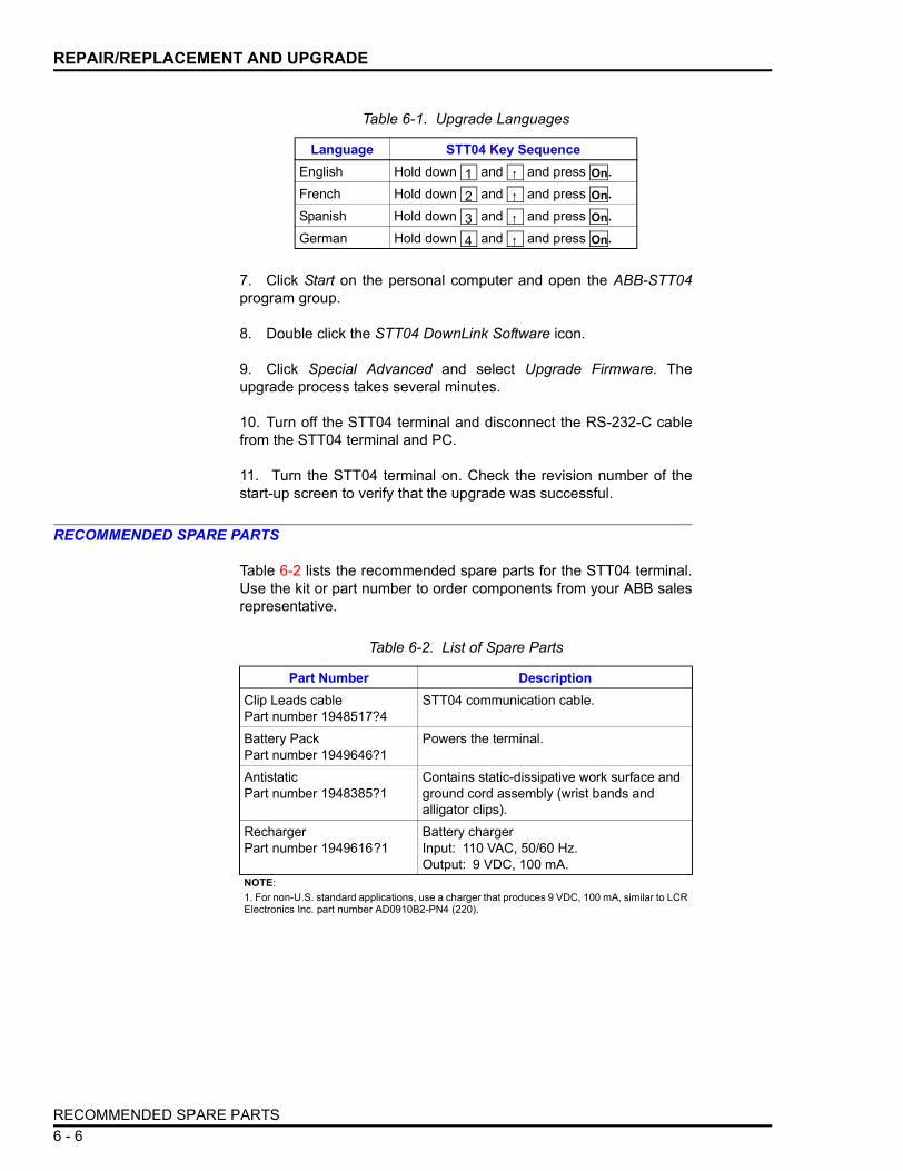
REPAIR/REPLACEMENT AND UPGRADE
7. Click Start on the personal computer and open the ABB-STT04program group.
8. Double click the STT04 DownLink Software icon.
9. Click Special Advanced and select Upgrade Firmware. Theupgrade process takes several minutes.
10. Turn off the STT04 terminal and disconnect the RS-232-C cablefrom the STT04 terminal and PC.
11. Turn the STT04 terminal on. Check the revision number of thestart-up screen to verify that the upgrade was successful.
RECOMMENDED SPARE PARTS
Table 6-2 lists the recommended spare parts for the STT04 terminal.Use the kit or part number to order components from your ABB salesrepresentative.
Table 6-1. Upgrade Languages
Language STT04 Key SequenceEnglish Hold down and and press .
French Hold down and and press .
Spanish Hold down and and press .
German Hold down and and press .
1 ↑ On
2 ↑ On
3 ↑ On
4 ↑ On
Table 6-2. List of Spare Parts
Part Number DescriptionClip Leads cable Part number 1948517?4
STT04 communication cable.
Battery PackPart number 1949646?1
Powers the terminal.
AntistaticPart number 1948385?1
Contains static-dissipative work surface and ground cord assembly (wrist bands and alligator clips).
RechargerPart number 1949616?1
Battery chargerInput: 110 VAC, 50/60 Hz.Output: 9 VDC, 100 mA.
NOTE: 1. For non-U.S. standard applications, use a charger that produces 9 VDC, 100 mA, similar to LCRElectronics Inc. part number AD0910B2-PN4 (220).
RECOMMENDED SPARE PARTS6 - 6

SECTION 7 - MAINTENANCE
INTRODUCTION
The STT04 terminal requires limited maintenance when operatedunder normal conditions. Periodically the battery pack requires charg-ing. Refer to Charging STT04 Terminal in Section 3.
If the STT04 terminal is inoperative, or if operation is faulty, refer tothe troubleshooting section of this manual.
CLEANING
Before cleaning, turn the terminal off and disconnect it from the com-munication wires or loop. Make sure the battery charger is also dis-connected. Wipe the unit down using a soft cloth dampened with anonabrasive, mild detergent. Do so as often as the installation envi-ronment requires.
WARNING
System maintenance must be performed only by qualified per-sonnel and only after securing equipment controlled by the cir-cuit. Altering or removing components from an active circuitmay upset the process being controlled.
CAUTION Do not allow cleaning solution or any other liquid to enter theterminal case as it will damage internal components.
INTRODUCTION 7 - 1

SECTION 8 - SUPPORT SERVICES
INTRODUCTION
ABB is ready to help in the use, application and repair of its products.Contact your nearest sales office to make requests for sales, applica-tions, installation, repair, overhaul and maintenance contract ser-vices.
REPLACEMENT PARTS
When making repairs, order replacement parts from an authorizedABB sales representative. Provide the following information:
1. Part description, part number and quantity.
2. Nomenclature and serial numbers (if applicable).
3. ABB instruction manual number, page number and reference fig-ure that identifies the part.
When ordering standard parts from ABB, use the part numbers anddescriptions from the spare parts lists. Order parts without commer-cial descriptions from the nearest ABB sales office.
SPARE PARTS LISTS
For available spare parts, refer to RECOMMENDED SPARE PARTSin Section 6.
TRAINING
ABB has modern training facilities available world wide for trainingyour personnel. On-site training is also available. Contact an ABBsales office for specific information and scheduling.
TECHNICAL DOCUMENTATION
Additional copies of this manual are available at the nearest ABBsales office for a reasonable charge.
INTRODUCTION 8 - 1

APPENDIX A - SMART POSITIONER
INTRODUCTION
This appendix covers the configuration and calibration functions ofthe Smart Positioner.
Refer to OPERATING PROCEDURES in Section 4 for information onthe following functions:
NOTE: To change calibration or configuration parameters of a smartfield device that is connected to an IMFBS01 module, the devicemust be taken off-line. This is done at the INFI 90 OPEN console.
CREATE/MODIFY CONFIGURATION
A configuration can be created off-line, without a connected fielddevice. Figure A-1 provides an overview of the configuration function.The following table details the configuration process.
• Send configurations. • Select configurations.• Get configurations. • Erase configurations.• View configurations. • Operational functions.
Figure A-1. Configuration Flowchart (AVS)
T01615A
SELECTDEVICETYPE
SELECTMODE
SELECTINPUT
CHARACTERIZATION
ENTERCONFIGURATION
ID TAG
ENTERDERIVATIVE
VALUE
ENTERLOW/HIGH
LIMIT SIGNALS
SELECTINPUT
SIGNAL
LOW FLOWSHUTOFF
SELECTDO3 ACTION
ENTERDAMPING
VALUE
ENTERLOWER/UPPERRANGE VALUES
ENTERPROPORTIONAL
GAIN (K )P
ENTERDERIVATION
ALARM
VALUESTUCK ALARM
YES/NO
ENTERINTEGRALVALUE (K )I
STORECONFIGURATION
ENTERLOW/HIGH
PRESSURE ALARMS
SELECTPRESSURE
UNITS
SELECTTRANSMITTER
TYPE
ENTERCHANNELNUMBER
ENTER 11INPUT/OUTPUT
POINTS
DIGITAL FUNCTIONGENERATOR
ABB FSK ANALOG OTHERS
CONFIGURE
INTRODUCTION A - 1

SMART POSITIONER
Key Display CommentsSelect NEW to create a configuration. To modify an existing configuration, select MODIFY. The screen sequence is the same, however, the MODIFY screens will appear with the values and cursor posi-tions as originally configured.
Select ABB FSK.
Use the down arrow key to select Positioner.
Enter a name for the configuration ID tag using up to 14 ASCII characters. To select a character, press the key that has the desired character. Continue to press the key until the desired character appears. Use the right arrow key to move to the next character. Use the left arrow key to go back to the previous charac-ter.Select DIGITAL. Use the up and down arrow keys to select mode.
NOTE: The DIGITAL selection should only be made when using an IMFBS01 field bus I/O module. Select ANALOG for all other cases.
This screen only appears in the DIGITAL mode. It is used to assign an address to the positioner for use with the field bus.
C O N F IG
CONFIGURATION→ NEW
MODIFYERASE
E N TE R
DEVICE TYPE→ ABB FSK
HART
E N TE R
TRANSMITTER TYPEPTS EQSBCN EQN
→ AVS TBN480 cond
E N TE R
STT04 CONFIGURATION[ ]
←PREVIOUS NEXT→
E N TE R
SELECT MODE:ANALOG
→ DIGITAL
E N TE R
ENTER CHANNEL #:nn
CREATE/MODIFY CONFIGURATIONA - 2

SMART POSITIONER
Move the indicator to the choice with the up and down arrow keys. Refer to the appropriate product instruction for input characterization types. For this example LINEAR is the input characterization type.
NOTE: The STT04 terminal is capable of displaying 3 input characterization types on the screen. Use the up and down arrow keys to view the additional input characterization types.Input lower range value using the number keys, then press . Input the upper range value.
Set this to YES to be alerted if the actuator has not moved for over two minutes with a change in the input signal.
NOTE: Review product instruction for details.
Select PSI units.
Proportional tuning constant. Use numbers between 1 and 0 for small drives and numbers greater than 1 for large drives.
NOTE: Review product instruction for details.
Integral tuning constant. This number will usually range from 1 to 40.
NOTE: Review product instruction for details.
Derivative tuning constant. This number will usually range between 2 and 70.
NOTE: Review product instruction for details.
Key Display Comments
E N TE R
INPUT CHAR→ LINEAR
SQUARE ROOTSQUARE
E N TE R
LOWER RANGE VALnn.nn
UPPER RANGE VALnn.nn
ENTER
E N TE R
VALVE STUCK ALARM
NO→ YES
E N TE R
PRESSURE UNIT
→ PSIBARS
E N TE R
Kp:Prop. Gain
nn.nn
E N TE R
Ki:Integral
nn.nn
E N TE R
Kd:Derivative
nn.nn
CREATE/MODIFY CONFIGURATION A - 3

SMART POSITIONER
Move the indicator to proper selection. Refer to the Smart Positioner instruction for an expla-nation of terms.
The input can be damped with a value of 1 to 5 sec-onds. A value of 0 will disable this parameter.
Set the deviation alarm in % of deviation from the set point.
Sets the low pressure alarm for the supply pressure.
Sets the percent of span that the digital output will be activated.
Sets the minimum input value (in % of span) that the control element will go to 0%.
Select a DO3 action with the arrow keys. Reference Positioner instruction for details.
NOTE: Scroll with the up and down arrow keys to view other selections.
Select YES using arrow keys.
Key Display Comments
E N TE R
INPUT SIGNAL:→ NORMAL ACT
REVERSE ACT
E N TE R
DAMPING:
(0 - 5 sec)
n SECS
E N TE R
DEVIATION ALARM
n.n%
E N TE R
LOW PRES ALARMnn.nn UNITS
HIGH PRES ALARMnn.nn UNITS
E N TE R
LOW LIMIT SIGNALnn.nn %
HIGH LIMIT SIGNALnn.nn %
E N TE R
LOW FLOW SHUTOFF
n.n %
E N TE R
DO3 ACTION:→ LO PRESS
DEVIATION ALARMVALVE STUCK ALARM
E N TE R
STORE THIS CONFIGURATION?
NO→ YES
CREATE/MODIFY CONFIGURATIONA - 4

SMART POSITIONER
CALIBRATION
This section details the calibration functions of the STT04 terminalwhile interfacing an positioner. There are four types of calibrationfunctions:
• Output D-to-A.• Manual position.• Input D-to-A.• Automatic position.
NOTES:1. When calibrating, a field device must be connected to theSTT04 terminal.
2. To change calibration or configuration parameters of a fielddevice that is connected to an IMFBS01 module, the transmittermust be taken off-line. This is done at the INFI 90 OPEN console.
After selecting a field device the READY screen appears. All calibra-tion functions can be performed on the selected device. Refer to Fig-ure A-2 for an overview of the calibration functions.
Configuration ID tag name just configured will be in the upper left corner if the configuration is saved. It becomes the working configuration.
Key Display Comments
E N TE R
ID TAGNAME
READY
Figure A-2. Calibration Flowchart (AVS)
T01332A
O U T P U T D -TO -A
IN P U T D -TO -A
M A N U AL P O S IT IO N
AU TO M AT IC P O S IT IO N
A D JU S T TO 4 m A
A P P LY 4 m A TO IN P U T
A D JU S T O U T P U T TO Z E RO
L IM IT S TO P S R E Q U IR E D
Y E S
N O
A D JU S T TO 2 0 m A
A P P LY 2 0 m A TO IN P U T
A D JU S T O U T P U T TO S PA N
AU TO C A L IB R ATIO N P E R F O R M E D
C A L IB R ATIO N C O M P LE T E
CALIBRATE
CALIBRATION A - 5
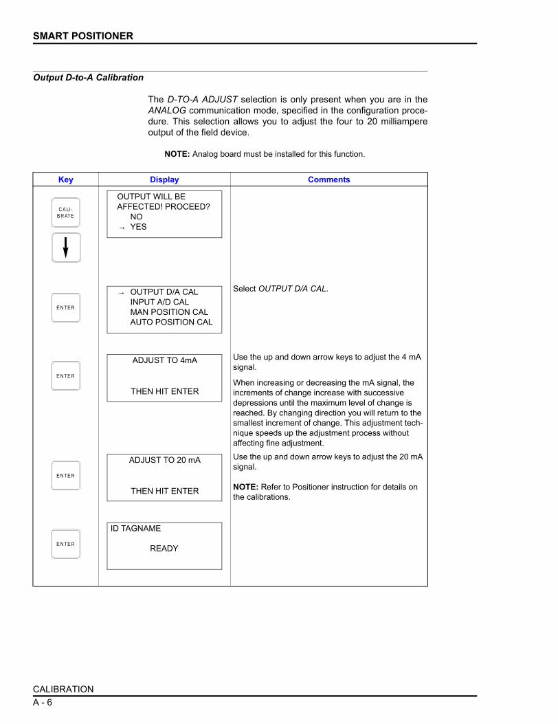
SMART POSITIONER
Output D-to-A Calibration
The D-TO-A ADJUST selection is only present when you are in theANALOG communication mode, specified in the configuration proce-dure. This selection allows you to adjust the four to 20 milliampereoutput of the field device.
NOTE: Analog board must be installed for this function.
Key Display Comments
Select OUTPUT D/A CAL.
Use the up and down arrow keys to adjust the 4 mA signal.
When increasing or decreasing the mA signal, the increments of change increase with successive depressions until the maximum level of change is reached. By changing direction you will return to the smallest increment of change. This adjustment tech-nique speeds up the adjustment process without affecting fine adjustment.Use the up and down arrow keys to adjust the 20 mA signal.
NOTE: Refer to Positioner instruction for details on the calibrations.
C A LI- B R ATE
OUTPUT WILL BEAFFECTED! PROCEED?
NO→ YES
E N TE R
→ OUTPUT D/A CALINPUT A/D CALMAN POSITION CALAUTO POSITION CAL
E N TE R
ADJUST TO 4mA
THEN HIT ENTER
E N TE R
ADJUST TO 20 mA
THEN HIT ENTER
E N TE R
ID TAGNAME
READY
CALIBRATIONA - 6
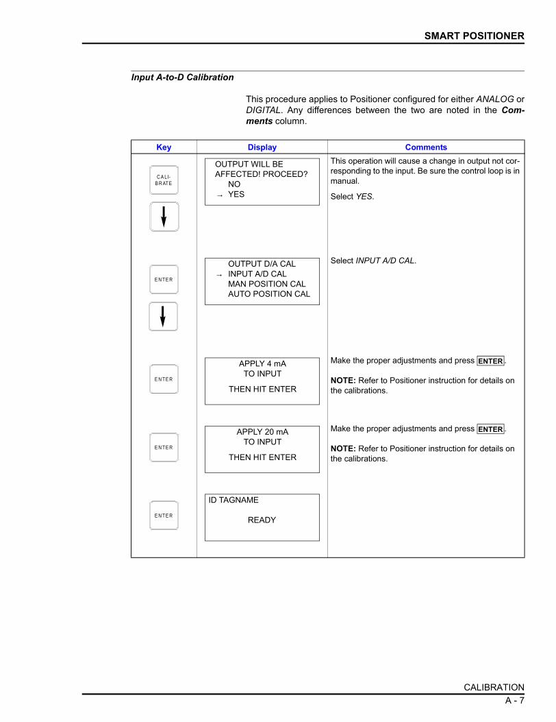
SMART POSITIONER
Input A-to-D Calibration
This procedure applies to Positioner configured for either ANALOG orDIGITAL. Any differences between the two are noted in the Com-ments column.
Key Display Comments
This operation will cause a change in output not cor-responding to the input. Be sure the control loop is in manual.
Select YES.
Select INPUT A/D CAL.
Make the proper adjustments and press .
NOTE: Refer to Positioner instruction for details on the calibrations.
Make the proper adjustments and press .
NOTE: Refer to Positioner instruction for details on the calibrations.
C A LI- B R ATE
OUTPUT WILL BEAFFECTED! PROCEED?
NO→ YES
E N TE R
OUTPUT D/A CAL→ INPUT A/D CAL
MAN POSITION CALAUTO POSITION CAL
E N TE R
APPLY 4 mATO INPUT
THEN HIT ENTER
ENTER
E N TE R
APPLY 20 mATO INPUT
THEN HIT ENTER
ENTER
E N TE R
ID TAGNAME
READY
CALIBRATION A - 7

SMART POSITIONER
Manual Position Calibration
This procedure applies to Positioner configured for either ANALOG orDIGITAL. Any differences between the two are noted in the Com-ments column.
Key Display Comments
This operation will cause a change in output not cor-responding to the input. Be sure the control loop is in manual.
Select YES.
Select MAN POSITION CAL.
Make the proper adjustments and press .
NOTE: Refer to Positioner instruction for details on the calibrations.
Make the proper adjustments and press .
NOTE: Refer to Positioner instruction for details on the calibrations.
C A LI- B R ATE
OUTPUT WILL BEAFFECTED! PROCEED?
NO→ YES
E N TE R
OUTPUT D/A CALINPUT A/D CAL
→ MAN POSITION CALAUTO POSITION CAL
E N TE R
ADJUST OUTPUTTO ZERO
THEN HIT ENTER
ENTER
E N TE R
ADJUST OUTPUTTO SPAN
THEN HIT ENTER
ENTER
E N TE R
ID TAGNAME
READY
CALIBRATIONA - 8

SMART POSITIONER
Automatic Position Calibration
This procedure applies to Positioner configured for either ANALOG orDIGITAL. Any differences between the two are noted in the Com-ments column.
Key Display Comments
This operation will cause a change in output not cor-responding to the input. Be sure the control loop is in manual.
Select YES.
Select AUTO POSITION CAL.
Limit stops are required for the AUTO POS CAL selection.
Select YES.
NOTE: Refer to Positioner instruction for details on the calibrations.The positioner is being automatically calibrated.
The positioner is calibrated.
C A LI- B R ATE
OUTPUT WILL BEAFFECTED! PROCEED?
NO→ YES
E N TE R
OUTPUT D/A CALINPUT A/D CALMAN POSITION CAL
→ AUTO POSITION CAL
E N TE R
LIMIT STOPS REQUIREDPROCEED?
NO→ YES
E N TE R AUTO CAL
STARTED
AUTO CAL
COMPLETE
CALIBRATION A - 9

SMART POSITIONER
SPECIAL FEATURE KEY FUNCTIONS
The special feature key selections available for the positioner varyfrom the other supported devices. The unique selections pertainingonly to the positioner, are as follows:
• Fix set point/cancel fix set point.• PID parameters.• Reset Totals.
Fix Set Point/Cancel Fix Set Point
This function locks the position demand set point at a user specifiedvalue. This set point value is maintained by the positioner until it iscanceled using CANCEL FIX SET.
Key Display Comments
C LE AR
ID TAGNAME
READY
Key Display CommentsSelect FIX SET POINT.If CANCEL FIX SET is selected, press and the fix set point is canceled and the READY screen appears.
Use the number key pad to input the desired fix set point value.
The set point remains at a fixed value until CANCEL FIX SET is selected.
S PE C IA LFE ATU R E
→ FIX SET POINTCANCEL FIX SETPID PARAMETERSSTANDARD CONFIG
ENTER
E N TE R
FIX SET POINT TO:nnn.nn%
E N TE R
ID TAGNAME
READY
SPECIAL FEATURE KEY FUNCTIONSA - 10

SMART POSITIONER
PID Parameters
Use this function to edit the PID parameters of the device. Theparameters are as follows:
Kp Proportional gain adjustment
Ki Integral, the number of resets per minute.
Kd Derivative rate action. Positions actuator and help to minimize over-shoot.
Key Display CommentsSelect PID PARAMETERS.
Use the number key pad to enter the desired gain value. Gain value range: 0.01 to 10
Use the number key pad to enter the desired gain value. Gain value range: 1 to 40
Use the number key pad to enter the desired gain value. Gain value range: 2 to 70
The PID parameters are sent to the positioner.
S PE C IA LFE ATU R E
FIX SET POINTCANCEL FIX SET
→ PID PARAMETERSSTANDARD CONFIGRESET TOTALS
E N TE R
Kp:
PROP. GAIN_
E N TE R
Ki:
PROP. GAIN_
E N TE R
Kd:
PROP. GAIN_
E N TE R
ID TAGNAME
READY
SPECIAL FEATURE KEY FUNCTIONS A - 11
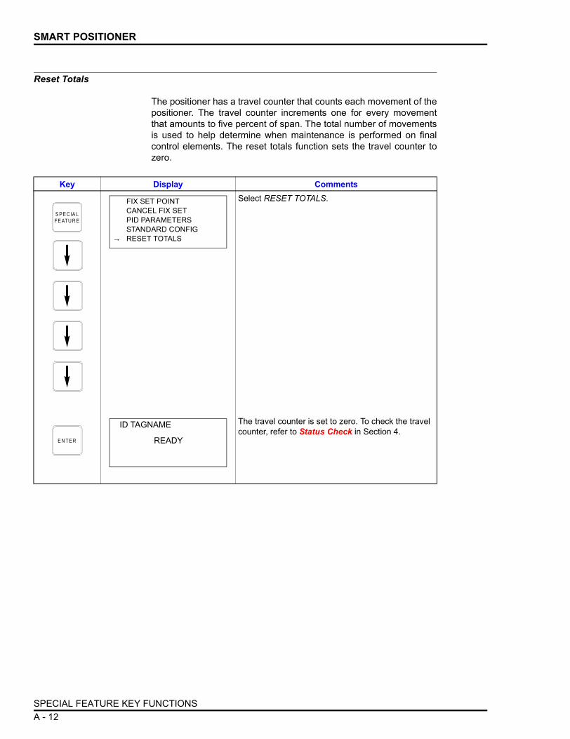
SMART POSITIONER
Reset Totals
The positioner has a travel counter that counts each movement of thepositioner. The travel counter increments one for every movementthat amounts to five percent of span. The total number of movementsis used to help determine when maintenance is performed on finalcontrol elements. The reset totals function sets the travel counter tozero.
Key Display CommentsSelect RESET TOTALS.
The travel counter is set to zero. To check the travel counter, refer to Status Check in Section 4.
S PE C IA LFE ATU R E
FIX SET POINTCANCEL FIX SETPID PARAMETERSSTANDARD CONFIG
→ RESET TOTALS
E N TE R
ID TAGNAME
READY
SPECIAL FEATURE KEY FUNCTIONSA - 12

SMART POSITIONER
Monitor Key Functions
The following functions apply to the positioner.
Use the monitor function key to monitor:
• Position. • Output air supply (O2).
• Set point. • Air pressure.
• Deviation. • Travel.
• Temperature. • Reverse.
• Input air supply. • Digital input.
• Output air supply (O1).
Key Display CommentsSelect a monitoring attribute using the down arrow key and press .
Additional monitor selections are:Input air supply Output air O1 port Output air O2 port Air presTravelReverseDigital input
Shows a real-time value for the selected variable.
M O N ITO R
POSITIONSET POINTDEVIATION
→ TEMPERATURE
ENTER
E N T E R
ID TAGNAMEMON. VARIABLE
nnn.nnUNITSGOOD STATUS
C LE AR
ID TAGNAME
READY
SPECIAL FEATURE KEY FUNCTIONS A - 13
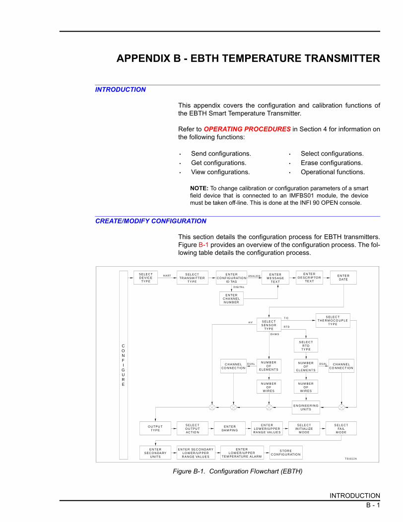
APPENDIX B - EBTH TEMPERATURE TRANSMITTER
INTRODUCTION
This appendix covers the configuration and calibration functions ofthe EBTH Smart Temperature Transmitter.
Refer to OPERATING PROCEDURES in Section 4 for information onthe following functions:
NOTE: To change calibration or configuration parameters of a smartfield device that is connected to an IMFBS01 module, the devicemust be taken off-line. This is done at the INFI 90 OPEN console.
CREATE/MODIFY CONFIGURATION
This section details the configuration process for EBTH transmitters.Figure B-1 provides an overview of the configuration process. The fol-lowing table details the configuration process.
• Send configurations. • Select configurations.• Get configurations. • Erase configurations.• View configurations. • Operational functions.
Figure B-1. Configuration Flowchart (EBTH)
T 01 612 A
S ELE C TD E VIC E
TY P E
S ELE C TS EN S O R
TY P E
N UM B ERO F
E LEM E NT S
S ELE C TRT D
TY P E
N UM B ERO F
W IR ES
N UM BERO F
W IRES
E N GIN EE R IN GU NITS
N UM BERO F
E L EM E N TS
C H A NN E LCO N NEC T ION
C H A NN E LCO NN EC T ION
E N TE RM E SS AGE
T E X T
E N TE RDATE
E N TE RD E SC R IP TO R
T E X T
S ELE C TTHE R M O C O U P LE
TY P E
E N TE RC O NF IG U RATIO N
ID TAG
E N TE RS EC O N DA RY
UN ITS
EN TE R SE C O N DARYLO W ER /U P PE RR A N GE VA LU E S
EN TE RL OW E R /UP PE R
TE M PE RATU RE A LA RM
O U T PU TTY P E
E NT E RLO W E R/U P PE RRA N GE VA LU E S
S ELE C TO U T PU TACT IO N
S EL E CTFA IL
M OD E
S EL E CTIN ITIA LIZE
M O D E
S TOR EC O N FIG UR ATIO N
E NT ERDA M PIN G
S EL E CTTR A NS M ITT E R
TY PE
E NT ERC HA N N E LN UM B ER
D IG ITA L
H A RT A N A LO G
T /C
RT D
O H M S
D UA LD UA L
m V
CONFI
GURE
INTRODUCTION B - 1

EBTH TEMPERATURE TRANSMITTER
Key Display CommentsSelect NEW to create a new configuration. To modify an existing configuration, select MODIFY. The screen sequence is the same, however, the MODIFY screens will appear with the values and cursor posi-tions as originally configured.
Select HART.
Select EBTH.
Enter a name for the configuration ID tag using up to eight ASCII characters. To select a character, press the key that has the desired character. Continue to press the key until the desired character appears. Use the right arrow key to move to the next charac-ter. Use the left arrow key to go back to the previous character.For this example select ANALOG.
Type a descriptive message using up to 32 charac-ters. This field can be used to note anything of impor-tance to the device or installation.
To select a character, press the key that has the desired character. Continue to press the key until the desired character appears. Use the right arrow key to move to the next character. Use the left arrow key to go back to the previous character.Type a descriptor string using up to 16 characters. This field can be used for notations about the device or process.
To select a character, press the key that has the desired character. Continue to press the key until the desired character appears. Use the right arrow key to move to the next character. Use the left arrow key to go back to the previous character.
C O N F IG
CONFIGURATION→ NEW
MODIFYERASE
E N TE R
DEVICE TYPE
ABB FSK→ HART
E N TE R
TRANSMITTER TYPEPTH → EBTHTB82 pH TB82 ORPTB82 pION TB82 CONC
E N TE R
STT04 CONFIGURATION[ ]
←PREVIOUS NEXT→
E N TE R
SELECT MODE:→ ANALOG
DIGITAL
E N TE R
MESSAGE:
←PREVIOUS NEXT→
E N TE R
DESCRIPTOR:
←PREVIOUS NEXT→
CREATE/MODIFY CONFIGURATIONB - 2

EBTH TEMPERATURE TRANSMITTER
Enter a day and press . Enter a month and press . Enter a year and press .
This date can represent the creation date of the con-figuration, the date the device or element was installed, or some other significant date.
For this example select T/C.
Select N type.
Choose the desired temperature unit.
Select LINEAR.
If FUNC GENERATOR is selected, specify 19 input and output points between 0 and 100%.
Refer to the Platinum Standard Series Smart Tem-perature Transmitter EBTH instruction for descrip-tion.
Enter a value between 0 and 100. Refer to the Plati-num Standard Series Smart Temperature Trans-mitter EBTH instruction for description.
Key Display Comments
E N TE R
E N TE R
DATE:DAY: nnMONTH: nnYEAR: nnnn
ENTERENTER ENTER
E N TE R
SENSOR TYPE:→ T/C RTD
mV OHMS
E N TE R
THERMOCOUPLE→ N B E
J K RS T C
E N TE R
ENGINEERING UNIT
→ oC oKoF oR
E N TE R
OUTPUT TYPE:→ LINEAR
FUNC GENERATOR
E N TE R
OUTPUT ACTION:→ NORMAL
REVERSE
E N TE R
DAMPING:(0-32 SEC)
nn.nn SECS
CREATE/MODIFY CONFIGURATION B - 3

EBTH TEMPERATURE TRANSMITTER
Enter the lower range temperature value and press . Input the upper range value.
Select an initialization mode using the arrow keys.
Refer to the Platinum Standard Series Smart Tem-perature Transmitter EBTH instruction for descrip-tion.
Select a fail mode using the arrow keys.
Refer to the Platinum Standard Series Smart Tem-perature Transmitter EBTH instruction for descrip-tion.
Enter up to 6 characters. Use familiar units to describe the output.
To select a character, press the key that has the desired character. Continue to press the key until the desired character appears. Use the right arrow key to move to the next character. Use the left arrow key to go back to the previous character.Input the lower range value and press . Input the upper range value.
Input the lower temperature alarm value and press .
Input the upper temperature alarm value and press .
Key Display Comments
E N TE R
E N TE R
LOWER RANGE VALnn.nn oC
UPPER RANGE VALnn.nn oC
ENTER
E N TE R
INITIALIZE MODE:→ LOW
HIGH
E N TE R
FAIL MODE:→ LOW
HIGHLAST
E N TE R
ENTERSECONDARY UNITS
nnnnnn
E N TE R
E N TE R
SECONDARY L.R._nn.nn UNITS
SECONDARY U.R.nn.nn UNITS
ENTER
E N TE R
E N TE R
LOWER TEMP ALARM_nn.nn UNITS
UPPER TEMP ALARM.nn.nn UNITS
ENTER
ENTER
CREATE/MODIFY CONFIGURATIONB - 4

EBTH TEMPERATURE TRANSMITTER
CALIBRATION
This section details the EBTH temperature transmitter calibrationfunctions of the STT04 terminal. There are two types of calibrationfunctions:
• Bench calibration.• D-to-A adjust.
NOTES:1. When calibrating, a field device must be connected to theSTT04 terminal.
2. To change calibration or configuration parameters of a fielddevice that is connected to an IMFBS01 module, the transmittermust be taken off-line. This is done at the INFI 90 OPEN console.
Refer to Figure B-2 for an overview of the calibration functions.
Select YES.
Configuration ID tag name just configured will be in the upper left corner if the configuration is saved. It becomes the working configuration.
Key Display Comments
E N TE R
STORE THIS CONFIGURATION
NO→ YES
E N TE R
ID TAGNAME
READY
Figure B-2. Calibration Flowchart (EBTH)
A PP LY 0 m VS O U R C E
A D JU S T H IG HC A L IBR ATIO NR E SIS TA N C E
B EN C HC A LIBR ATIO N
A D JU S T LO WC A LIBR ATIO N
C A L IBR ATIO NC O M P LE TE
A D JU S T H IG HC A LIBR ATIO N
A PP LY 0 Ω A PP LY 250 Ω
A D JU S T LO WC A L IBR ATIO NR E SIS TA N C E
T 019 10 A
A PP LY 100 m VS O U R C E
CALIBRATE
D -TO -AC A L
M E TH O D
A R RO WK EY S
M E TER VA LU EE N TRY
A D JU S TO U TPU TTO 4 m A
A D JU S TO U TPU TTO 20 m A
4 m AC A LIBR ATIO N
E N TE R M ETE RVALU E 4.000
20 m AC A L IBR ATIO N
E N TE R M ETE RVALU E 20 .000
CALIBRATION B - 5

EBTH TEMPERATURE TRANSMITTER
Bench Calibration
This procedure applies to EBTH Transmitters configured for eitherANALOG or DIGITAL. Any difference between the two are noted inthe Comments column.
Key Display CommentsThis operation will cause a change in output not cor-responding to the input. Be sure the control loop is in manual.
Select YES.
Select BENCH CALIB with the down arrow key.
Enter the low and high calibration voltages.
Enter the low and high calibration resistances.
Apply 0.00 mV to the transmitter. A message appears that indicates a stabilization time.
NOTE: Refer to the EBTH instruction for detailed wir-ing diagrams of this procedure.
C A LI- B R ATE
OUTPUT WILL BEAFFECTED! PROCEED?
NO→ YES
E N TE R
CALIBRATION
D-TO-A ADJUST→ BENCH CALIB.
E N TE R
LOW CALIBn.nnn mV
HIGH CALIBn.nnn mV
E N TE R
LOW CALIB RESn.nn Ω
HIGH CALIB RESnnn.nn Ω
E N TE R
APPLY 0.00 mV
AT 3(+), 4(-)THEN HIT ENTER
WAITING FOR CALIBRATION
CALIBRATIONB - 6

EBTH TEMPERATURE TRANSMITTER
D-to-A Adjust
The D-TO-A ADJUST selection is only present when you are in theANALOG communication mode. There are two methods available toadjust the four to 20 milliampere output:
• Arrow key.• Meter value entry for HART devices.
Apply 100 mV to the transmitter. A message appears that indicates a stabilization time.
NOTE: Refer to the EBTH instruction for detailed wir-ing diagrams of this procedure.
Apply 0 Ω to the transmitter. A message appears that indicates a stabilization time.
NOTE: Refer to the EBTH instruction for detailed wir-ing diagrams of this procedure.
Apply 250 Ω to the transmitter. A message appears that indicates a stabilization time.
NOTE: Refer to the EBTH instruction for detailed wir-ing diagrams of this procedure.
Key Display Comments
E N TE R
APPLY 100.00 mV
AT 3(+), 4(-)THEN HIT ENTER
WAITING FOR CALIBRATION
E N TE R
APPLY 0.00 ΩSHORT
1-2, 2-3, 3-4THEN HIT ENTER
E N TE R
APPLY 250 ΩSHORT 1-2, 3-4
Ω AT 2-3THEN HIT ENTER
E N TE R
ID TAGNAME
READY
CALIBRATION B - 7

EBTH TEMPERATURE TRANSMITTER
ARROW KEY ADJUSTMENT
Use this function to adjust the four to 20 milliampere output of the fielddevice using the up and down arrow keys.
Key Display CommentsThis operation will cause a change in output not cor-responding to the input. Be sure the control loop is in manual.
Select YES.
Select D-TO-A ADJUST.
Select UPDOWN ARROW KEYS.
Use the arrow keys to adjust the 4 mA signal.
NOTE: When increasing or decreasing the mA sig-nal, the increments of change increase with succes-sive depressions until the maximum level of change is reached. By changing direction you will return to the smallest increment of change. This adjustment technique speeds up the adjustment process without affecting fine adjustment.Use the arrow keys to adjust the 20 mA signal.
C A LI- B R ATE
OUTPUT WILL BEAFFECTED! PROCEED?
NO→ YES
E N TE R
CALIBRATION→ D-TO-A ADJUST
BENCH CALIB.
E N TE R
D/A CAL USING→ UPDOWN ARROW KEYS
METER VALUE ENTRY
E N TE R
ADJUST TO 4 mA
THEN HIT ENTER
E N TE R
ADJUST TO 20 mA
THEN HIT ENTER
E N TE R
ID TAGNAME
READY
CALIBRATIONB - 8
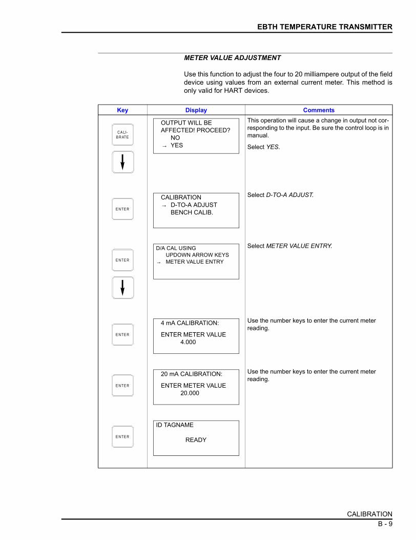
EBTH TEMPERATURE TRANSMITTER
METER VALUE ADJUSTMENT
Use this function to adjust the four to 20 milliampere output of the fielddevice using values from an external current meter. This method isonly valid for HART devices.
Key Display CommentsThis operation will cause a change in output not cor-responding to the input. Be sure the control loop is in manual.
Select YES.
Select D-TO-A ADJUST.
Select METER VALUE ENTRY.
Use the number keys to enter the current meter reading.
Use the number keys to enter the current meter reading.
C A LI- B R ATE
OUTPUT WILL BEAFFECTED! PROCEED?
NO→ YES
E N TE R
CALIBRATION→ D-TO-A ADJUST
BENCH CALIB.
E N TE R
D/A CAL USINGUPDOWN ARROW KEYS
→ METER VALUE ENTRY
E N TE R
4 mA CALIBRATION:
ENTER METER VALUE4.000
E N TE R
20 mA CALIBRATION:
ENTER METER VALUE20.000
E N TE R
ID TAGNAME
READY
CALIBRATION B - 9

APPENDIX C - EQS TEMPERATURE TRANSMITTER
INTRODUCTION
This appendix covers the configuration and calibration functions ofthe EQS Temperature Transmitter. Refer to OPERATING PROCE-DURES in Section 4 for information on the following functions:
NOTE: To change calibration or configuration parameters of a smartfield device that is connected to an IMFBS01 module, the devicemust be taken off-line. This is done at the INFI 90 OPEN console.
CREATE/MODIFY CONFIGURATION
Configuration can be created off-line, without a connected fielddevice. Refer to Figure C-1 for an overview of the configurationfunction. The following table details the configuration process.
• Send configurations. • Select configurations.• Get configurations. • Erase configurations.• View configurations. • Operational functions.
Figure C-1. Configuration Flowchart (EQS)
T01617A
SELECTDEVICETYPE
SELECTMODE
SELECTSENSOR
TYPE
NUMBEROF
ELEMENTS
SELECTOHMS
SELECTmV
SELECTRTDTYPE
NUMBEROF
WIRES
NUMBEROF
WIRES
ENGINEERINGUNITS
NUMBEROF
ELEMENTS
SELECTTHERMOCOUPLE
TYPE
ENTERCONFIGURATION
ID TAG
ENTERSECONDARY
UNITS
ENTER SECONDARYLOWER/UPPERRANGE VALUES
ENTERLOWER/UPPER
TEMPERATURE ALARM
OUTPUTTYPE
ENTERLOWER/UPPERRANGE VALUES
SELECTOUTPUTACTION
SELECTFAIL
MODE
SELECTINITIALIZE
MODE
STORECONFIGURATION
ENTERDAMPING
SELECTTRANSMITTER
TYPE
ENTERCHANNELNUMBER
DIGITAL
ABB FSK ANALOG
T/C
RTD
OHMSmV
CONFIGURE
INTRODUCTION C - 1

EQS TEMPERATURE TRANSMITTER
Key Display CommentsSelect NEW to create a new configuration. To modify an existing configuration, select MODIFY. The screen sequence is the same, however, the MODIFY screens will appear with the values and cursor posi-tions as originally configured.
Select ABB FSK.
Use the right arrow key to select EQS.
Enter a name for the configuration ID tag using up to 14 ASCII characters. To select a character, press the key that has the desired character. Continue to press the key until the desired character appears. Use the right arrow key to move to the next character. Use the left arrow key to go back to the previous character.
For this example select ANALOG.
For this example select T/C.
Select N type.
Choose the desired temperature unit.
C O N F IG
CONFIGURATION→ NEW
MODIFYERASE
E N TE R
DEVICE TYPE→ ABB FSK
HART
E N TE R
TRANSMITTER TYPEPTS → EQSBCN EQNAVS TB480 cond
E N TE R
STT04 CONFIGURATION[ ]
←PREVIOUS NEXT→
E N TE R
SELECT MODE:→ ANALOG
DIGITAL
E N TE R
SENSOR TYPE:→ T/C RTD
mV OHMS
E N TE R
THERMOCOUPLE→ N B E
J K RS T C
E N TE R
ENGINEERING UNIT→ oC
oFoK
CREATE/MODIFY CONFIGURATIONC - 2

EQS TEMPERATURE TRANSMITTER
Select LINEAR.
If FUNC GENERATOR is selected, specify 5 input and output points between 0 and 100%.
Refer to the Platinum Standard Series Smart Tem-perature Transmitter EQS instruction for descrip-tion.
Enter a value between 0 and 32. Refer to the Plati-num Standard Series Smart Temperature Trans-mitter EQS instruction for description.
Enter the lower range temperature value and press . Input the upper range value.
Select an initialization mode using the arrow keys.
Refer to the Platinum Standard Series Smart Tem-perature Transmitter EQS instruction for descrip-tion.
Select a fail mode using the arrow keys.
Refer to the Platinum Standard Series Smart Tem-perature Transmitter EQS instruction for descrip-tion.
Enter up to 6 characters. Use familiar units to describe the output.
To select a character, press the key that has the desired character. Continue to press the key until the desired character appears. Use the right arrow key to move to the next character. Use the left arrow key to go back to the previous character. Press when finished.Input the lower range value and press . Input the upper range value.
Key Display Comments
E N TE R
OUTPUT TYPE:→ LINEAR
FUNC GENERATOR
E N TE R
OUTPUT ACTION:→ NORMAL
REVERSE
E N TE R
DAMPING:(0-32 SEC)
nn.nn SECS
E N TE R
LOWER RANGE VALnn.nn oC
UPPER RANGE VALnn.nn oC
ENTER
E N TE R
INITIALIZE MODE:→ LOW
HIGH
E N TE R
FAIL MODE:→ LOW
HIGHLAST
E N TE R
ENTERSECONDARY UNITS
nnnnnn
ENTER
E N TE R
SECONDARY L.R._nn.nn UNITS
SECONDARY U.R.nn.nn UNITS
ENTER
CREATE/MODIFY CONFIGURATION C - 3

EQS TEMPERATURE TRANSMITTER
CALIBRATION
This section details the EQS temperature transmitter calibration func-tions of the STT04 terminal. There are two types of calibration func-tions:
• Bench calibration.• D-to-A adjust.
NOTES:1. When calibrating, a field device must be connected to theSTT04 terminal.
2. To change calibration or configuration parameters of a fielddevice that is connected to an IMFBS01 module, the transmittermust be taken off-line. This is done at the INFI 90 OPEN console.
Refer to Figure C-2 for an overview of the calibration functions.
Bench Calibration
This procedure applies to EQS Transmitters configured for eitherANALOG or DIGITAL. Any differences between the two are noted inthe Comments column.
Input the lower and upper temperature alarm values and press .
Lower and upper temperature alarms are user con-figured. The temperature is based on the cell. The default alarm settings are shown here. The defaults are also the lower and upper limits of the alarm.Select YES.
Key Display Comments
E N TE R
LOWER TEMP ALARM_nn.nn UNITS
UPPER TEMP ALARM.nn.nn UNITS
ENTER
E N TE R
STORE THIS CONFIGURATION
NO→ YES
E N TE R
ID TAGNAME
READY
CALIBRATIONC - 4

EQS TEMPERATURE TRANSMITTER
Figure C-2. Calibration Flowchart (EQS)
Key Display Comments
This operation will cause a change in output not cor-responding to the input. Be sure the control loop is in manual.
Select YES.
Select BENCH CALIB with the down arrow key.
Enter the low and high calibration voltages.
Enter the low and high calibration resistances.
A PP LY 0 m VS OU R C E
A D JU S T H IG HC A LIBR ATIO NR E SIS TA N C E
B EN C HC A LIBR ATIO N
A D JU S T LO WC A LIBR ATIO N
C A LIBR ATIO NC O MP LE TE
A D JU S T H IG HC A LIBR ATIO N
A PP LY 0 Ω A PP LY 250 Ω
A D JU S T LOWC A LIBR ATIO NR E SIS TA N C E
T 01 9 10 A
A PP LY 100 m VS OU R C E
CALIBRATE
D -TO-AC A L
M E TH O D
A R ROWK EY S
M E TER VA LU EE N TRY
A D JU S TO U TPU TTO 4 mA
A D JU S TOU TPU TTO 20 m A
4 m AC A LIBR ATIO N
E N TE R M ETE RVALU E 4 .000
20 m AC A LIBR ATIO N
E N TE R M ETE RVALU E 20 .000
C A LI- B R ATE
OUTPUT WILL BEAFFECTED! PROCEED?
NO→ YES
E N TE R
CALIBRATION
D-TO-A ADJUST→ BENCH CALIB.
E N TE R
LOW CALIBn.nnn mV
HIGH CALIBn.nnn mV
E N TE R
LOW CALIB RESn.nn Ω
HIGH CALIB RESnnn.nn Ω
CALIBRATION C - 5

EQS TEMPERATURE TRANSMITTER
Apply 0.00 mV to the transmitter.
NOTE: Refer to the EQS instruction for detailed wir-ing diagrams of this procedure.
Apply 100 mV to the transmitter.
Apply 0 Ω to the transmitter.
NOTE: Refer to the EQS instruction for detailed wir-ing diagrams of this procedure.
Apply 250 Ω to the transmitter.
Use the arrow keys to adjust the 4 mA signal.
NOTE: When increasing or decreasing the mA sig-nal, the increments of change increase with succes-sive depressions until the maximum level of change is reached. By changing direction you will return to the smallest increment of change. This adjustment technique speeds up the adjustment process without affecting fine adjustment.Use the arrow keys to adjust the 20 mA signal.
Key Display Comments
E N TE R
APPLY 0.00 mV
AT 3(+), 4(-)THEN HIT ENTER
E N TE R
APPLY 100.00 mV
AT 3(+), 4(-)THEN HIT ENTER
E N TE R
APPLY 0.00 ΩSHORT
1-2, 2-3, 3-4THEN HIT ENTER
E N TE R
APPLY 250 ΩSHORT 1-2, 3-4
Ω AT 2-3THEN HIT ENTER
E N TE R
ADJUST TO 4 mA
THEN HIT ENTER
E N TE R
ADJUST TO 20 mA
THEN HIT ENTER
E N TE R
ID TAGNAME
READY
CALIBRATIONC - 6

EQS TEMPERATURE TRANSMITTER
D-to-A Adjust
The D-TO-A ADJUST selection is only present when you are in theANALOG communication mode, specified in the configuration proce-dure. This selection allows you to adjust the four to 20 milliampereoutput of the field device.
Key Display CommentsThis operation will cause a change in output not cor-responding to the input. Be sure the control loop is in manual.
Select YES.
Select D-TO-ADJUST.
Use the arrow keys to adjust the 4 mA signal.
NOTE: When increasing or decreasing the mA sig-nal, the increments of change increase with succes-sive depressions until the maximum level of change is reached. By changing direction you will return to the smallest increment of change. This adjustment technique speeds up the adjustment process without affecting fine adjustment.Use the arrow keys to adjust the 20 mA signal.
C A LI- B R ATE
OUTPUT WILL BEAFFECTED! PROCEED?.
NO→ YES
E N TE R
CALIBRATION→ D-TO-A ADJUST
BENCH CALIB.
E N TE R
ADJUST TO 4 mA
THEN HIT ENTER
E N TE R
ADJUST TO 20 mA
THEN HIT ENTER
E N TE R
ID TAGNAME
READY
CALIBRATION C - 7

APPENDIX D - PTH PRESSURE TRANSMITTER
INTRODUCTION
This appendix covers the configuration and calibration functions ofthe PTH Pressure Transmitter.
Refer to OPERATING PROCEDURES in Section 4 for information onthe following functions:
NOTE: To change calibration or configuration parameters of a smartfield device that is connected to an IMFBS01 module, the devicemust be taken off-line. This is done at the INFI 90 OPEN console.
CREATE/MODIFY CONFIGURATION
A configuration can be created off-line, without a connected fielddevice. Refer to Figure D-1 for an overview of the configurationfunction. The following table details the configuration process.
• Send configurations. • Select configurations.• Get configurations. • Erase configurations.• View configurations. • Operational functions.
Figure D-1. Configuration Flowchart (PTH)
T 01 3 41 B
S ELE C TD E VIC E
TY P E
S ELE C TM O D E
S ELE C TO U TPU T
TY P E
S ELE C TO U TPU TAC TIO N
E N TE RC O N F IG U R ATIO N
ID TAG
E N T E RDA M PIN G
VALU E
E N TE RS EC O N DA RY
U N ITS
S ELE C TE N GIN E E R IN G
U N ITS
E N TE RLO W E R /U P PE R
S EC O N DA RY VALU E S
E N TE RLO W E R /U P PE R
TE M PE R ATU R E A LAR M S
E N TE RLOW E R /U P PE RR A N GE VA LU E S
S ELE C TIN ITIA L IZ E
M OD E
S TO R EC O N FIG U R ATIO N
S ELE C TFA IL
M OD E
S ELE C TTR A N S M ITTE R
TY P E
E N TE RC H A N N E LN U M B ER
E N TE R 5IN P U T/OU TPU T
P OIN TS
D IG ITA L
F U N C TIO NG E N E R ATO R
H A RT A N A LO G
O T H E R S
CONFIGURE
E N TE RM E SS AG E
TE X T
E N TE RDATE
E N T E RD E SC R IPTO R
TE X T
INTRODUCTION D - 1

PTH PRESSURE TRANSMITTER
Key Display CommentsSelect NEW to create a configuration. To modify an existing configuration, select MODIFY. The screen sequence is the same, however, the MODIFY screens will appear with the values and arrow posi-tions as they were originally configured.
Select HART.
Select PTH.
Enter a name for the configuration ID tag using up to eight ASCII characters. To select a character, press the key that has the desired character. Continue to press the key until the desired character appears. Use the right arrow key to move to the next charac-ter. Use the left arrow key to go back to the previous character.Select ANALOG.
NOTE: The DIGITAL selection should only be made when using the device in the multidrop. A CHANNEL # prompt appears when DIGITAL is selected.
Type a descriptive message using up to 32 charac-ters. This field can be used to note anything of impor-tance to the device or installation.
To select a character, press the key that has the desired character. Continue to press the key until the desired character appears. Use the right arrow key to move to the next character. Use the left arrow key to go back to the previous character.Type a descriptor string using up to 16 characters. This field can be used for notations about the device or process.
To select a character, press the key that has the desired character. Continue to press the key until the desired character appears. Use the right arrow key to move to the next character. Use the left arrow key to go back to the previous character.
C O N F IG
CONFIGURATION→ NEW
MODIFYERASE
E N TE R
DEVICE TYPE
ABB FSK→ HART
E N TE R
TRANSMITTER TYPE→PTH EBTH
TB82 pH TB82 ORPTB82 pION TB82 CONC
E N TE R
STT04 CONFIGURATION[ ]
←PREVIOUS NEXT→
E N TE R
SELECT MODE: → ANALOG
DIGITAL
E N TE R
MESSAGE:
←PREVIOUS NEXT→
E N TE R
DESCRIPTOR:
←PREVIOUS NEXT→
CREATE/MODIFY CONFIGURATIOND - 2
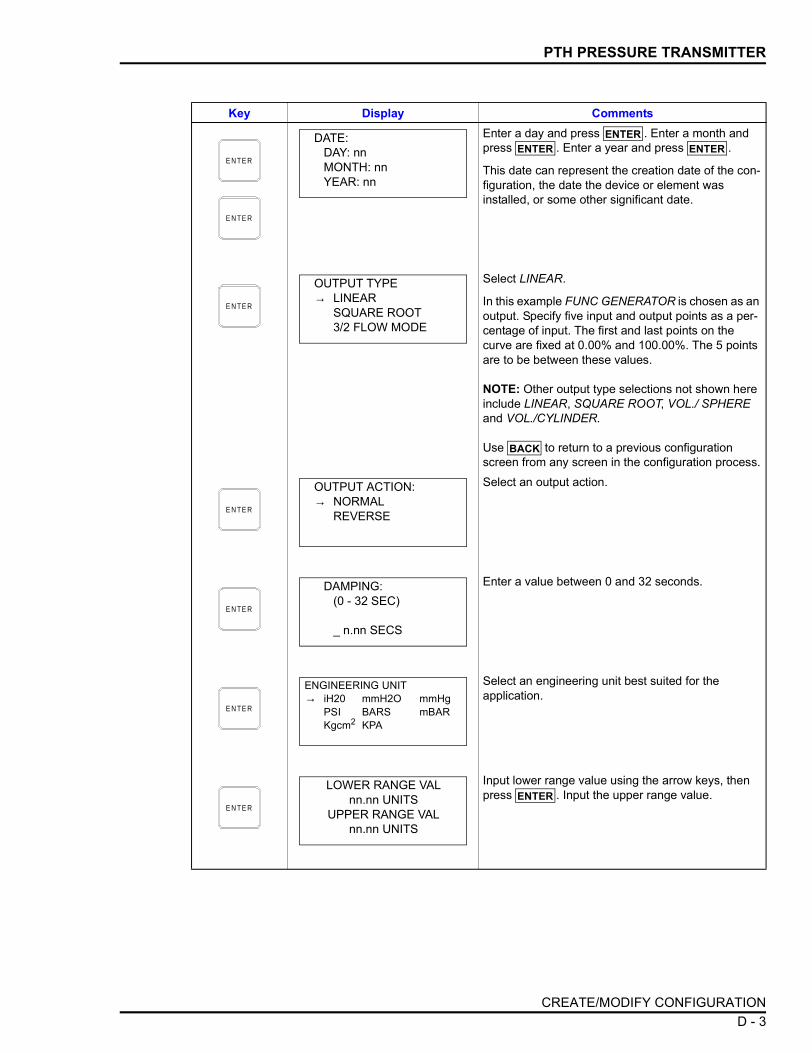
PTH PRESSURE TRANSMITTER
Enter a day and press . Enter a month and press . Enter a year and press .
This date can represent the creation date of the con-figuration, the date the device or element was installed, or some other significant date.
Select LINEAR.
In this example FUNC GENERATOR is chosen as an output. Specify five input and output points as a per-centage of input. The first and last points on the curve are fixed at 0.00% and 100.00%. The 5 points are to be between these values.
NOTE: Other output type selections not shown here include LINEAR, SQUARE ROOT, VOL./ SPHERE and VOL./CYLINDER.
Use to return to a previous configuration screen from any screen in the configuration process.Select an output action.
Enter a value between 0 and 32 seconds.
Select an engineering unit best suited for the application.
Input lower range value using the arrow keys, then press . Input the upper range value.
Key Display Comments
E N TE R
E N TE R
DATE:DAY: nnMONTH: nnYEAR: nn
ENTERENTER ENTER
E N TE R
OUTPUT TYPE→ LINEAR
SQUARE ROOT3/2 FLOW MODE
BACK
E N TE R
OUTPUT ACTION:→ NORMAL
REVERSE
E N TE R
DAMPING:(0 - 32 SEC)
_ n.nn SECS
E N TE R
ENGINEERING UNIT→ iH20 mmH2O mmHg
PSI BARS mBARKgcm2 KPA
E N TE R
LOWER RANGE VALnn.nn UNITS
UPPER RANGE VALnn.nn UNITS
ENTER
CREATE/MODIFY CONFIGURATION D - 3

PTH PRESSURE TRANSMITTER
Refer to the Platinum Standard Series Smart Pres-sure Transmitter PTH instruction for mode descrip-tion.
Make a selection using the arrow keys.
This is a 6-character alphanumeric designation to represent values in user familiar units.
To select a character, press the key that has the desired character. Continue to press the key until the desired character appears. Use the right arrow key to move to the next character. Use the left arrow key to go back to the previous character. Specify values using the number keypad. The UNITS displayed will be those designated in the previous screen. After entering value press .
Lower and upper temperature alarms are user con-figurable alarms. The temperature is based on the cell. The default alarms setting are shown here. The defaults are also the lower and upper limits of the alarm.
NOTE: Use to return to a previous configura-tion screen from any screen in the configuration pro-cess.Select YES.
Key Display Comments
E N TE R
INITIALIZE MODE:→ LOW
HIGH
E N TE R
FAIL MODE:→ LOW
HIGHLAST
E N TE R
ENTERSECONDARY UNITS_nnnnnn
E N TE R
SECONDARY L. R.nn.nn UNITS
SECONDARY U. R.nn.nn UNITS
ENTER
E N TE R
LOWER TEMP ALARM-40.00°C
UPPER TEMP ALARM85.00°C
BACK
E N TE R
STORE THIS CONFIGURATION?
NO→ YES
E N TE R
ID TAGNAME
READY
CREATE/MODIFY CONFIGURATIOND - 4

PTH PRESSURE TRANSMITTER
CALIBRATION
This section details the PTH pressure transmitter calibration functionsusing an STT04 terminal. There are three types of calibration func-tions:
• Bench calibration.• Rezero.• D-to-A adjust.
NOTES:1. When calibrating, a field device must be connected to theSTT04 terminal.
2. To change calibration or configuration parameters of a fielddevice that is connected to an IMFBS01 module, the transmittermust be taken off-line. This is done at the INFI 90 OPEN console.
Refer to Figure D-2 for an overview of the calibration functions.
Figure D-2. Calibration Flowchart (PTH)
T 01 3 40 A
D IG ITA L
A N A LO G
CA L IBR ATIO NC O M P LE TE
B EN CH
R E ZE RO
E NTE R LOWC A LIBR ATIO N
P R ES S U R E
D -TO -AC A L
M E TH O D
C A LM E TH O D
A R RO WK EY S
A R RO WK EY S
M E TER VA LU EE N TRY
M E TER VA LU EE N TRY
A D JU S TO U TPU TTO 4 m A
A D JU S TO U TPU TTO 4 m A
A D JU S TO U TPU T
TO 20 m A
A D JU S TO U TPU T
TO 20 m A
4 m ACA LIBR ATIO N
E N TE R M ET ERVALU E 4 .000
4 m ACA LIBR ATIO N
E N TE R M ET ERVALU E 4 .000
20 m ACA LIBR ATIO N
E N TE R M ET ERVALU E 20.000
20 m ACA LIBR ATIO N
E N TE R M ET ERVALU E 20.000
E Q UA LIZEP R ES S U R E
E NTE R H IGHCA LIBR ATIO N
P R ES S U R E
R E ZE ROC O M P LE TE
A PP LY LO WCA LIBR ATIO N
P R ES S U R E
CALIBRATE
A PP LY H IG HCA LIBR ATIO N
P R ES S U R E
CALIBRATION D - 5

PTH PRESSURE TRANSMITTER
Bench Calibration
This procedure applies to PTH pressure transmitters configured foreither ANALOG or DIGITAL. Any differences between the two arenoted in the Comments column.
Key Display Comments
This operation will cause a change in output not cor-responding to the input. Be sure the control loop is in manual.
Select YES.
Select BENCH CALIB.If the transmitter is configured for digital operation, the D-TO-A ADJUST selection would not appear.
Enter the low calibration pressure value and press . Enter the high calibration pressure value.
Apply the low calibration pressure to the input of transmitter as specified earlier.
Apply the high calibration pressure to the input of transmitter as specified earlier.
C A LI- B R ATE
OUTPUT WILL BEAFFECTED! PROCEED?
NO→ YES
E N TE R
CALIBRATIOND-TO-A ADJUST
→ BENCH CALIB.REZERO
E N TE R
LOW CALIB PRESSUREnn.nn UNITS
HIGH CALIB PRESSUREnn.nn UNITS
ENTER
E N TE R
APPLY PRESSURE OF nn.nn UNITS
THEN HIT ENTER
E N TE R
APPLY PRESSURE OFnn.nn UNITS
THEN HIT ENTER
CALIBRATIOND - 6

PTH PRESSURE TRANSMITTER
Select UPDOWN ARROW KEYS.
NOTE: Refer to METER VALUE ADJUSTMENT for details about meter value entry.
Adjust transmitter output using the up and down arrow keys. If configured digitally this adjust display does not appear.
NOTE: When increasing or decreasing the mA sig-nal, the increments of change increase with succes-sive depressions until the maximum level of change is reached. By changing direction the smallest incre-ment of change returns. This technique speeds up the adjustment process without affecting fine adjustment.Adjust the transmitter output using the up and down arrow keys.
Key Display Comments
E N TE R
D/A CAL USING→UPDOWN ARROW KEYS
METER VALUE ENTRY
E N TE R
ADJUST TO 4 mA
THEN HIT ENTER
E N TE R
ADJUST TO 20 mA
THEN HIT ENTER
E N TE R
ID TAGNAME
READY
CALIBRATION D - 7

PTH PRESSURE TRANSMITTER
Rezero
The rezero procedure allows you to zero the transmitter without goingthrough the complete bench calibration procedure.
D-to-A Adjust
The D-TO-A ADJUST selection is only present when you are in theANALOG communication mode. There are two methods available toadjust the four to 20 milliampere output:
• Arrow key. • Meter value entry for HART devices.
Key Display Comments
This operation will cause a change in output not cor-responding to the input. Be sure the control loop is in manual.
Select YES.
Select REZERO.
If digitally configured, the D-TO-A ADJUST selection will not appear.
Apply zero value to the transmitter.
Rezero is complete.
C A LI- B R ATE
OUTPUT WILL BEAFFECTED! PROCEED?
NO→ YES
E N TE R
CALIBRATION:D-TO-A ADJUSTBENCH CALIB.
→ REZERO
E N TE R
APPLY PRESSURE OFnn.nn UNITS
THEN HIT ENTER
E N TE R
ID TAGNAME
READY
CALIBRATIOND - 8

PTH PRESSURE TRANSMITTER
ARROW KEY ADJUSTMENT
Use this function to adjust the four to 20 milliampere output of the fielddevice using the up and down arrow keys.
Key Display CommentsThis operation will cause a change in output not cor-responding to the input. Be sure the control loop is in manual.
Select YES.
Select D-TO-A ADJUST.
Select UPDOWN ARROW KEYS.
Use the arrow keys to adjust the 4 mA signal.
NOTE: When increasing or decreasing the mA sig-nal, the increments of change increase with succes-sive depressions until the maximum level of change is reached. By changing direction you will return to the smallest increment of change. This adjustment technique speeds up the adjustment process without affecting fine adjustment.Use the arrow keys to adjust the 20 mA signal.
C A LI- B R ATE
OUTPUT WILL BEAFFECTED! PROCEED?
NO→ YES
E N TE R
CALIBRATION→ D-TO-A ADJUST
BENCH CALIB.
E N TE R
D/A CAL USING→ UPDOWN ARROW KEYS
METER VALUE ENTRY
E N TE R
ADJUST TO 4 mA
THEN HIT ENTER
E N TE R
ADJUST TO 20 mA
THEN HIT ENTER
E N TE R
ID TAGNAME
READY
CALIBRATION D - 9

PTH PRESSURE TRANSMITTER
METER VALUE ADJUSTMENT
Use this function to adjust the four to 20 milliampere output of the fielddevice using values from an external current meter. This method isonly valid for HART devices.
Key Display CommentsThis operation will cause a change in output not cor-responding to the input. Be sure the control loop is in manual.
Select YES.
Select D-TO-A ADJUST.
Select METER VALUE ENTRY.
Use the number keys to enter the current meter reading.
Use the number keys to enter the current meter reading.
C A LI- B R ATE
OUTPUT WILL BEAFFECTED! PROCEED?
NO→ YES
E N TE R
CALIBRATION→ D-TO-A ADJUST
BENCH CALIB.
E N TE R
D/A CAL USINGUPDOWN ARROW KEYS
→METER VALUE ENTRY
E N TE R
4 mA CALIBRATIONENTER METER VALUE
THEN HIT ENTER
E N TE R
20 mA CALIBRATIONENTER METER VALUE
THEN HIT ENTER
E N TE R
ID TAGNAME
READY
CALIBRATIOND - 10

APPENDIX E - PTS PRESSURE TRANSMITTER
INTRODUCTION
This appendix covers the configuration and calibration functions ofthe PTS Pressure Transmitter.
Refer to OPERATING PROCEDURES in Section 4 for information onthe following functions:
NOTE: To change calibration or configuration parameters of a smartfield device that is connected to an IMFBS01 module, the devicemust be taken off-line. This is done at the INFI 90 OPEN console.
CREATE/MODIFY CONFIGURATION
A configuration can be created off-line, without a connected fielddevice. Refer to Figure E-1 for an overview of the configurationfunction. The following table details the configuration process.
• Send configurations. • Select configurations.• Get configurations. • Erase configurations.• View configurations. • Operational functions.
Figure E-1. Configuration Flowchart (PTS)
T01341A
ENTER DAMPING CONSTANTID TAG SELECT MODE
ENTER CHANNEL NUMBER
SAVE CONFIGURATION
DIGITAL
ANALOG SELECT TRANSMITTER
TYPE
ENTER SECONDARY
UNITS
SELECT INITIALIZE
MODE
SELECT FAIL MODE
ENTER UPPER TEMPERATURE
ALARM
SELECT OUTPUT TYPE
ENTER SECONDARY
LOWER RANGE
ENTER SECONDARY
UPPER RANGE
SELECT ENGINEERING
UNITS
ENTER LOWER RANGE VALUE
ENTER UPPER RANGE VALUE
CONFIGURE
SELECT OUTPUT ACTION
ENTER LOWER TEMPERATURE
ALARM
INTRODUCTION E - 1

PTS PRESSURE TRANSMITTER
Key Display CommentsSelect NEW to create a configuration. To modify an existing configuration, select MODIFY. The screen sequence is the same, however, the MODIFY screens will appear with the values and arrow posi-tions as they were originally configured.
Select ABB FSK.
Use the down arrow key to select PTS.
Enter a name for the configuration ID tag using up to 14 ASCII characters. To select a character, press the key that has the desired character. Continue to press the key until the desired character appears. Use the right arrow key to move to the next character. Use the left arrow key to go back to the previous charac-ter.Select ANALOG.
NOTE: The DIGITAL selection should only be made when using an IMFBS01 field bus I/O module. A CHANNEL # prompt appears when DIGITAL is selected.
Select LINEAR. For a function generator example, refer to Appendix G.
Use to return to a previous configuration screen from any screen in the configuration process.
Use the arrow keys to select an output action.
Enter a value between 0 and 32 seconds.
C O N F IG
CONFIGURATION→ NEW
MODIFYERASE
E N TE R
DEVICE TYPE→ ABB FSK
HART
E N TE R
TRANSMITTER TYPE→ PTS EQS
BCN EQNAVS TB480 cond
E N TE R
STT04 CONFIGURATION[ ]
←PREVIOUS NEXT→
E N TE R
SELECT MODE:→ ANALOG
DIGITAL
E N TE R
OUTPUT TYPE:→ LINEAR
SQUARE ROOT3/2 FLOW MODE
BACK
E N TE R
OUTPUT ACTION:→ NORMAL
REVERSE
E N TE R
DAMPING:(0 - 32 SEC)
_ nn.nn SEC
CREATE/MODIFY CONFIGURATIONE - 2

PTS PRESSURE TRANSMITTER
Select an engineering unit best suited for the application.
Input lower range value using the arrow keys, then press . Input the upper range value.
Refer to the Platinum Standard Series Smart Pres-sure Transmitter PTS instruction for mode descrip-tion.
Make a selection using the arrow keys.
This is a 6-character alphanumeric designation to represent values in user familiar units.
To select a character, press the key that has the desired character. Continue to press the key until the desired character appears. Use the right arrow key to move to the next character. Use the left arrow key to go back to the previous character. Press when finished. Specify values using the number keypad. The UNITS displayed will be those designated in the previous screen. After entering value press .
Lower and upper temperature alarms are user con-figured. The temperature is based on the cell. The default alarms setting are shown here. The defaults are also the lower and upper limits of the alarm.
NOTE: Use to return to a previous configura-tion screen from any screen in the configuration pro-cess.
Key Display Comments
E N TE R
ENGINEERING UNIT→iH20cmH2OmmHg
PSIMPAKPABARSmBARKgcm2
E N TE R
LOWER RANGE VAL.nn.nn UNITS
UPPER RANGE VAL.nn.nn UNITS
ENTER
E N TE R
INITIALIZE MODE:→ LOW
HIGH
E N TE R
FAIL MODE:→ LOW
HIGHLAST
E N TE R
ENTERSECONDARY UNITS_nnnnnn
ENTER
E N TE R
SECONDARY L. R.nn.nn UNITS
SECONDARY U. R.nn.nn UNITS
ENTER
E N TE R
LOWER TEMP ALARM-40.00°C
UPPER TEMP ALARM85.00°C
BACK
CREATE/MODIFY CONFIGURATION E - 3

PTS PRESSURE TRANSMITTER
CALIBRATION
This section details the PTS pressure transmitter calibration functionsusing an STT04 terminal. There are three types of calibration func-tions:
• Bench calibration.• Rezero.• D-to-A adjust.
NOTES:1. When calibrating, a field device must be connected to theSTT04 terminal.
2. To change calibration or configuration parameters of a fielddevice that is connected to an IMFBS01 module, the transmittermust be taken off-line. This is done at the INFI 90 OPEN console.
Refer to Figure E-2 for an overview of the calibration functions.
Bench Calibration
This procedure applies to PTS pressure transmitters configured foreither ANALOG or DIGITAL. Any difference between the two arenoted in the Comments column.
Select YES.Key Display Comments
E N TE R
STORE THIS CONFIGURATION?
NO→ YES
E N TE R
ID TAGNAME
READY
CALIBRATIONE - 4

PTS PRESSURE TRANSMITTER
Figure E-2. Calibration Flowchart (PTS)
Key Display Comments
This operation will cause a change in output not cor-responding to the input. Be sure the control loop is in manual.
Select YES.
Select BENCH CALIB.If the transmitter is configured for digital operation, the D-TO-A ADJUST selection would not appear.
T 01 3 40 A
D IG ITA L
A N A LO G
C A LIBR ATIO NC O M P LE TE
B EN C H
R E ZE RO
E N TE R LOWC A LIBR ATIO N
P R ES S U R E
D -TO -AC A L
M E TH O D
C A LM E TH O D
A R RO WK EY S
A R RO WK EY S
M E TER VA LU EE N TRY
M E TER VA LU EE N TRY
A D JU S TO U TPU TTO 4 m A
A D JU S TO U TPU TTO 4 m A
A D JU S TO U TPU T
TO 20 m A
A D JU S TO U TPU T
TO 20 m A
4 m AC A LIBR ATIO N
E N TE R M ET ERVALU E 4.000
4 m AC A LIBR ATIO N
E N TE R M ET ERVALU E 4.000
20 m AC A LIBR ATIO N
E N TE R M ET ERVALUE 20 .000
20 m AC A LIBR ATIO N
E N TE R M ET ERVALUE 20 .000
E Q UA LIZEP R ES S U R E
E N TE R H IG HC A LIBR ATIO N
P R ES S U R E
R E ZE ROC O M P LE TE
A PP LY LO WC A LIBR ATIO N
P R ES S U R E
CALIBRATE
A PP LY H IG HC A LIBR ATIO N
P R ES S U R E
C A LI- B R ATE
OUTPUT WILL BEAFFECTED! PROCEED?
NO→ YES
E N TE R
CALIBRATIOND-TO-A ADJUST
→ BENCH CALIB.REZERO
CALIBRATION E - 5

PTS PRESSURE TRANSMITTER
Enter the low calibration pressure value and press . Enter the high calibration pressure value.
Apply the low calibration pressure to the input of transmitter as specified earlier.
Apply the high calibration pressure to the input of transmitter as specified earlier.
Adjust transmitter output using the up and down arrow keys. If configured digitally this adjust display does not appear.
NOTE: When increasing or decreasing the mA sig-nal, the increments of change increase with succes-sive depressions until the maximum level of change is reached. By changing direction the smallest incre-ment of change returns. This technique speeds up the adjustment process without affecting fine adjustment.Adjust the transmitter output using the up and down arrow keys.
Key Display Comments
E N TE R
LOW CALIB PRESSUREnn.nn UNITS
HIGH CALIB PRESSUREnn.nn UNITS
ENTER
E N TE R
APPLY PRESSURE OFnn.nn UNITS
THEN HIT ENTER
E N TE R
APPLY PRESSURE OFnn.nn UNITS
THEN HIT ENTER
E N TE R
ADJUST TO 4 mA
THEN HIT ENTER
E N TE R
ADJUST TO 20 mA
THEN HIT ENTER
E N TE R
ID TAGNAME
READY
CALIBRATIONE - 6

PTS PRESSURE TRANSMITTER
Rezero
The rezero procedure allows you to zero the transmitter without goingthrough the complete bench calibration procedure.
Key Display Comments
This operation will cause a change in output not cor-responding to the input. Be sure the control loop is in manual.
Select YES.
Select REZERO.
If digitally configured, the D-TO-A ADJUST selection will not appear.
Apply zero value to the transmitter.
Rezero is complete.
C A LI- B R ATE
OUTPUT WILL BEAFFECTED! PROCEED?
NO→ YES
E N TE R
CALIBRATION:D-TO-A ADJUSTBENCH CALIB.
→ REZERO
E N TE R
APPLY PRESSURE OF
nn.nn UNITSTHEN HIT ENTER
E N TE R
ID TAGNAME
READY
CALIBRATION E - 7

PTS PRESSURE TRANSMITTER
D-to-A Adjust
The D-TO-A ADJUST selection is only present when you are in theANALOG communication mode, specified in the configuration proce-dure. This selection allows you to adjust the four to 20 milliampereoutput of the field device.
Key Display Comments
This operation will cause a change in output not cor-responding to the input. Be sure the control loop is in manual.
Select YES.
Select D-TO-A ADJUST.
Use the arrow keys to adjust the 4 mA signal.
NOTE: When increasing or decreasing the mA sig-nal, the increments of change increase with succes-sive depressions until the maximum level of change is reached. By changing direction you will return to the smallest increment of change. This adjustment technique speeds up the adjustment process without affecting fine adjustment.Use the arrow keys to adjust the 20 mA signal.
C A LI- B R ATE
OUTPUT WILL BEAFFECTED! PROCEED?
NO→ YES
E N TE R
CALIBRATION→ D-TO-A ADJUST
BENCH CALIB.REZERO
E N TE R
ADJUST TO 4 mA
THEN HIT ENTER
E N TE R
ADJUST TO 20 mA
THEN HIT ENTER
E N TE R
ID TAGNAME
READY
CALIBRATIONE - 8

APPENDIX F - HART UNIVERSAL
INTRODUCTION
This appendix covers the universal HART configuration function. AnSTT04 can communicate with an unsupported HART device and editthe following fields; ID tag, device address, message and descriptor.
HART UNIVERSAL CONFIGURATION
Refer to Figure F-1 for an overview of the HART configurationfunction. The table that follows details the configuration process.
Figure F-1. Configuration Flowchart (HART)
Key Display CommentsSelect HART.
T 01614B
S ELE C TD EV IC E
TY PE
E N TE RD E SC R IP TO R
E N TE RC O N FIG U R ATIO N
N AM E
DA M P IN G
S AVEC O N FIG U R ATIO N
EN TERM E S SAG E
EN TER LOW E RA N D U PP E R
R AN G E VALU E
S E LEC TTR A N S M ITTE R
TYP E
EN TERDATE
SE LE C TM O D E
EN TE RC H AN N ELN U M BE R
SE LE C TEN G IN E E R IN G
U N ITS
CONFI
GURE
E N TE R
DEVICE TYPE
ABB FSK→ HART
INTRODUCTION F - 1

HART UNIVERSAL
Select HART UNIVERSAL.
Enter a name for the configuration ID tag using up to 8 ASCII characters. To select a character, press the key that has the desired character. Continue to press the key until the desired character appears. Use the right arrow key to move to the next character. Use the left arrow key to go back to the previous charac-ter.For this example select ANALOG.
Type a descriptive message using up to 32 charac-ters. This field can be used to note anything of impor-tance to the device or installation.
To select a character, press the key that has the desired character. Continue to press the key until the desired character appears. Use the right arrow key to move to the next character. Use the left arrow key to go back to the previous character.Type a descriptor string using up to 16 characters. This field can be used for notations about the device or process.
To select a character, press the key that has the desired character. Continue to press the key until the desired character appears. Use the right arrow key to move to the next character. Use the left arrow key to go back to the previous character.
Key Display Comments
E N TE R
TRANSMITTER TYPETB82 pH TB82 ORPTB82 pION TB82 CONCTZID/AZH → HART UNIV
E N TE R
STT04 CONFIGURATION[ ]
←PREVIOUS NEXT→
E N TE R
SELECT MODE:→ ANALOG
DIGITAL
E N TE R
MESSAGE:
←PREVIOUS NEXT→
E N TE R
DESCRIPTOR:
←PREVIOUS NEXT→
HART UNIVERSAL CONFIGURATIONF - 2

HART UNIVERSAL
Enter a day and press . Enter a month and press . Enter a year and press .
This date can represent the creation date of the con-figuration, the date the device or element was installed, or some other significant date.
Enter a value between 0 and 100. Refer to the Plati-num Standard Series Smart Temperature Trans-mitter EBTH instruction for description.
Select engineering units. This appears only for pres-sure and temperature transmitters.
Enter the lower range temperature value and press . Input the upper range value.
Select YES.
Configuration ID tag name just configured will be in the upper left corner if the configuration is saved. It becomes the working configuration.
Key Display Comments
E N TE R
DATE:DAY : nnMONTH : nnYEAR : nnnn
ENTERENTER ENTER
E N TE R
DAMPING:(0-100 SEC)
nn.nn SECS
E N TE R
ENGINEERING UNIT→ nnnnnn nnnnnn
nnnnnn nnnnnn
E N TE R
LOWER RANGE VALnn.nn oC
UPPER RANGE VALnn.nn oC
ENTER
E N TE R
STORE THIS CONFIGURATION
NO→ YES
E N TE R
ID TAGNAME
READY
HART UNIVERSAL CONFIGURATION F - 3

APPENDIX G - BCN PRESSURE TRANSMITTER
INTRODUCTION
This appendix covers the configuration and calibration functions of the BCNPressure Transmitter.
Refer to OPERATING PROCEDURES in Section 4 for information on thefollowing functions:
NOTE: To change calibration or configuration parameters of a smartfield device that is connected to an IMFBS01 module, the devicemust be taken off-line. This is done at the INFI 90 OPEN console.
CREATE/MODIFY CONFIGURATION
A configuration can be created off-line, without a connected field device.Figure G-1 provides and overview of the configuration process. The follow-ing table details the configuration process.
• Send configurations. • Select configurations.
• Get configurations. • Erase configurations.
• View configurations. • Operational functions.
Figure G-1. Configuration Flowchart (BCN)
T01616A
SELECTDEVICE
TYPE
SELECTMODE
SELECTOUTPUT
TYPE
SELECTOUTPUTACTION
ENTERCONFIGURATION
ID TAG
ENTERDAMPING
VALUE
ENTERSECONDARY
UNITS
SELECTENGINEERING
UNITS
ENTER SECONDARYLOWER/UPPERRANGE VALUES
ENTERLOWER/UPPERRANGE VALUES
SELECTINITIALIZE
MODE
STORECONFIGURATION
SELECTFAIL
MODE
SELECTTRANSMITTER
TYPE
ENTERCHANNELNUMBER
ENTER 5INPUT/OUTPUT
POINTS
DIGITAL FUNCTIONGENERATOR
ABB FSK ANALOG OTHERS
CONFIGURE
INTRODUCTION G - 1

BCN PRESSURE TRANSMITTER
Key Display Comments
Select NEW to create a new configuration. To modify an existing configuration, select MODIFY. The screen sequence is the same, however, the MODIFY screens will appear with the values and cursor posi-tions as originally configured.
Select ABB FSK as device type.
Use the down arrow key and select BCN.
Enter a name for the configuration ID tag using up to 14 ASCII characters. To select a character, press the key that has the desired character. Continue to press the key until the desired character appears. Use the right arrow key to move to the next character. Use the left arrow key to go back to the previous character.
Select DIGITAL (device in this mode defaults to below 4 mA, independent of input). Use the up and down arrow keys to select mode.
NOTE: The DIGITAL selection should only be made when using an IMFBS01 field bus I/O module. Select ANALOG for all other cases.
If ANALOG is selected, ENTER CHANNEL # screen will not appear. The next screen will be TRANSMIT-TER TYPE. This screen is used to assign an address to the transmitter for use with the field bus. The address range is 1 through 8.
C O N F IG
CONFIGURATION→ NEW
MODIFYERASE
E N TE R
DEVICE TYPE
→ ABB FSKHART
E N TE R
TRANSMITTER TYPEPTS EQS
→ BCN EQNAVS TBN480 cond
E N TE R
STT04 CONFIGURATION[ ]
←PREVIOUS NEXT→
E N TE R
SELECT MODE:ANALOG
→ DIGITAL
E N TE R
ENTER CHANNEL #:nn
CREATE/MODIFY CONFIGURATIONG - 2
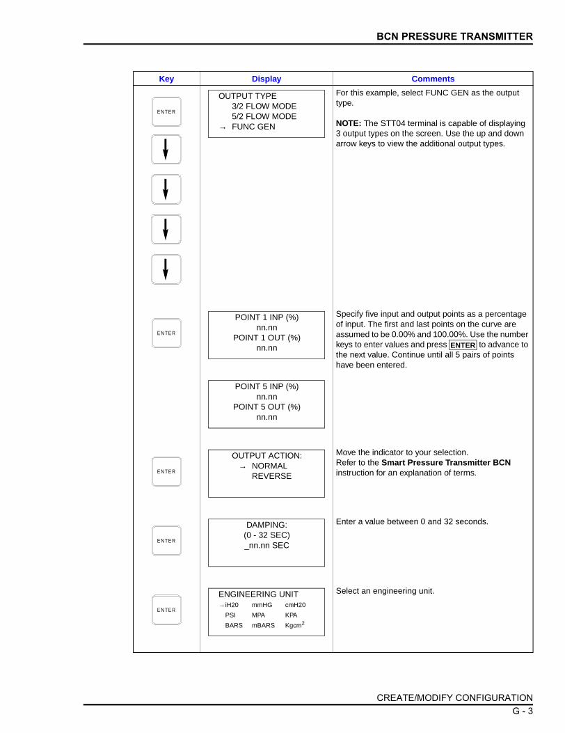
BCN PRESSURE TRANSMITTER
For this example, select FUNC GEN as the output type.
NOTE: The STT04 terminal is capable of displaying 3 output types on the screen. Use the up and down arrow keys to view the additional output types.
Specify five input and output points as a percentage of input. The first and last points on the curve are assumed to be 0.00% and 100.00%. Use the number keys to enter values and press to advance to the next value. Continue until all 5 pairs of points have been entered.
Move the indicator to your selection. Refer to the Smart Pressure Transmitter BCN instruction for an explanation of terms.
Enter a value between 0 and 32 seconds.
Select an engineering unit.
Key Display Comments
E N TE R
OUTPUT TYPE3/2 FLOW MODE5/2 FLOW MODE
→ FUNC GEN
E N TE R
POINT 1 INP (%)nn.nn
POINT 1 OUT (%)nn.nn ENTER
POINT 5 INP (%)nn.nn
POINT 5 OUT (%)nn.nn
E N TE R
OUTPUT ACTION:→ NORMAL
REVERSE
E N TE R
DAMPING:(0 - 32 SEC)_nn.nn SEC
E N TE R
ENGINEERING UNIT→iH20 mmHG cmH20
PSI MPA KPA
BARS mBARS Kgcm2
CREATE/MODIFY CONFIGURATION G - 3

BCN PRESSURE TRANSMITTER
Input lower range value using the number keys and press . Input the upper range value. The UNITS displayed will be those designated in the pre-vious screen.
Select LOW using the arrow keys.
Refer to the Smart Pressure Transmitter BCN instruction for mode description.
Select LOW using the arrow keys.
This is a 6 character alphanumeric designation to represent values in user familiar units.
To select a character, press the key that has the desired character. Continue to press the key until the desired character appears. Use the right arrow key to move to the next character. Use the left arrow key to go back to the previous character. Press when finished.
Specify secondary values using the number keys. The UNITS displayed will be those designated in the previous screen. After entering a value press
.
Make a selection using the arrow keys.
The Configuration ID tag name just configured will be in the upper left corner if the configuration is saved. It becomes the working configuration.
Key Display Comments
E N TE R
LOWER RANGE VAL.nn.nn UNITS
UPPER RANGE VAL.nn.nn UNITS
ENTER
E N TE R
INITIALIZE MODE:→ LOW
HIGH
E N TE R
FAIL MODE→ LOW
HIGH LAST
E N TE R
ENTERSECONDARY UNITS_nnnnnn
ENTER
E N TE R
SECONDARY L. R.nn.nn UNITS
SECONDARY U. R.nn.nn UNITS ENTER
E N TE R
STORE THIS CONFIGURATION? NO→ YES
E N TE R
ID TAGNAME
READY
CREATE/MODIFY CONFIGURATIONG - 4
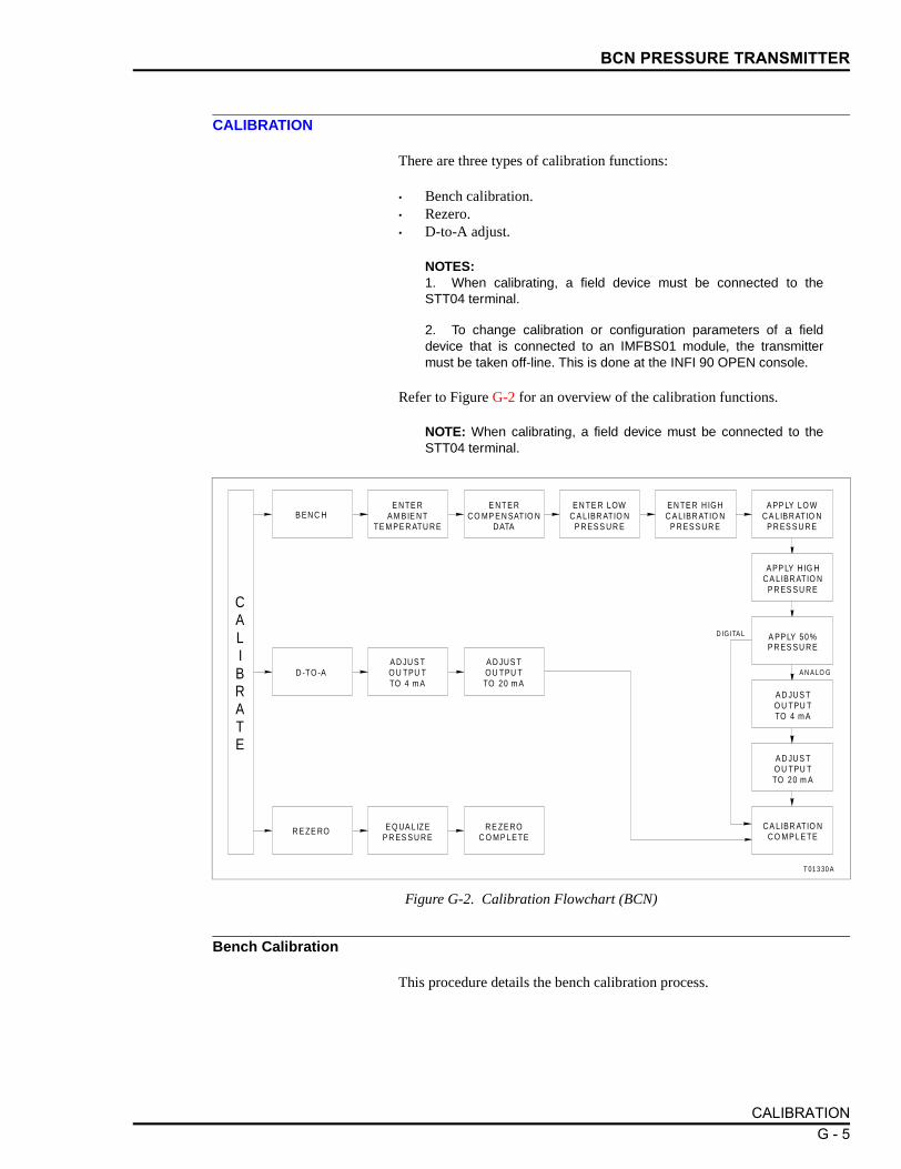
BCN PRESSURE TRANSMITTER
CALIBRATION
There are three types of calibration functions:
• Bench calibration.• Rezero.• D-to-A adjust.
NOTES:1. When calibrating, a field device must be connected to theSTT04 terminal.
2. To change calibration or configuration parameters of a fielddevice that is connected to an IMFBS01 module, the transmittermust be taken off-line. This is done at the INFI 90 OPEN console.
Refer to Figure G-2 for an overview of the calibration functions.
NOTE: When calibrating, a field device must be connected to theSTT04 terminal.
Bench Calibration
This procedure details the bench calibration process.
Figure G-2. Calibration Flowchart (BCN)
T 01 3 30 A
D IG ITA L
A N A LO G
A PP LY LO W C A LIBR ATIO N
P R ES S U R EB EN C H
D -TO -A
R E ZE RO
E N TE R A M BIE N T
TE M PE R ATU R E
A D JU S T O U TPU T TO 4 m A
A D JU S T OU TPU T TO 20 m A
E Q UA LIZE P R ES S U R E
E N TE R C O MP E N SATIO N
DATA
R E ZE RO C O M P LE TE
E N TE R LOW C A LIBR ATIO N
P R ES S U R E
A PP LY H IG H C A LIBR ATIO N
P R ES S U R E
A D JU S T O U TPU T TO 4 m A
A PP LY 50 % P R ES S U R E
A D JU S T O U TPU T TO 20 m A
C A LIBR ATIO N C O M P L E TE
CALIBRATE
E N TE R H IGH C A LIBR ATIO N
P R ES S U R E
CALIBRATION G - 5

BCN PRESSURE TRANSMITTER
Key Display Comments
This operation will cause a change in output not cor-responding to the input. Be sure the control loop is in manual.
Select YES.
Select BENCH CALIB.
If configured digitally, the D-TO-A ADJUST selection will not appear.
Enter the field device ambient temperature in degrees Celsius using the number keypad. The sur-rounding room temperature can be used for this tem-perature value.
The compensation data is based on characteristics of the individual transducers for temperature correc-tion. Refer to the Smart Pressure Transmitter BCN instruction.
There are 5 sets of data, A through E. Press to advance to the next set of data. This data should match the tag located in the electronics side of the transmitter. In certain cases, zero shift is entered as a percentage value at -25°C and 85°C.
NOTE: After a value for C is entered D and E are dis-played and after E is entered a checksum value is requested.
There are also 5 sets of data, A through E, for span shift. Press to advance to the next set of data. In certain cases, span shift is entered as a per-centage value at -25°C and 85°C.
NOTE: After a value for C is entered D and E are dis-played and after E is entered a checksum value is requested.
C A LI- B R ATE
OUTPUT WILL BEAFFECTED! PROCEED?
NO→ YES
E N TE R
CALIBRATIOND-TO-A ADJUST
→ BENCH CALIB.REZERO
E N TE R
ENTER TRANSMITTERAMBIENT TEMP.
nn C
E N TE R
ENTER COMP DATANO
→ YES
E N TE R
ZERO SHIFTA. 000000000B. 000000000C. 000000000D. 000000000E. 000000000
ENTER
E N TE R
SPAN SHIFTA. 000000000B. 000000000C. 000000000D. 000000000E. 000000000
ENTER
CALIBRATIONG - 6

BCN PRESSURE TRANSMITTER
Enter the low calibration pressure using the number keypad. Press . Then enter the high calibra-tion pressure.
Apply the low range value to the input of transmitter as specified earlier.
Apply the high range value to the input of transmitter as specified earlier.
Apply the middle range value. This value is calcu-lated by STT04 terminal using low and high values.
If configured digitally this adjust selection does not appear. Adjust transmitter output using up and down arrow keys.
NOTE: When increasing or decreasing the mA sig-nal, the increments of change increase with succes-sive depressions until the maximum level of change is reached. By changing direction the smallest incre-ment of change returns. This technique speeds up the process without affecting fine adjustment.
Adjust the transmitter output using up and down arrow keys.
Key Display Comments
E N TE R
LOW CALIB PRESSUREnn.nn UNITS
HIGH CALIB PRESSUREnn.nn UNITS
ENTER
E N TE R
APPLY PRESSURE OFnn.nn UNITS
THEN HIT ENTER
E N TE R
APPLY PRESSURE OFnn.nn UNITS
THEN HIT ENTER
E N TE R
APPLY PRESSURE OFnn.nn UNITS
THEN HIT ENTER
E N TE R
ADJUST TO 4 mA
THEN HIT ENTER
E N TE R
ADJUST TO 20 mA
THEN HIT ENTER
E N TE R
ID TAGNAME
READY
CALIBRATION G - 7

BCN PRESSURE TRANSMITTER
Rezero
The rezero procedure allows you to zero the transmitter without goingthrough the complete bench calibration procedure.
Key Display Comments
This operation will cause a change in output not cor-responding to the input. Be sure the control loop is in manual.
Select YES.
Select REZERO.
If digitally configured, the D-TO-A ADJUST selection will not appear.
Apply zero value to the transmitter.
Rezero is complete.
C A LI- B R ATE
OUTPUT WILL BEAFFECTED! PROCEED?
NO→ YES
E N TE R
CALIBRATION:D-TO-A ADJUSTBENCH CALIB.
→ REZERO
E N TE R
APPLY PRESSURE OF
nn.nn
THEN HIT ENTER
E N TE R
ID TAGNAME
READY
CALIBRATIONG - 8

BCN PRESSURE TRANSMITTER
D-to-A Adjust
The D-TO-A ADJUST selection is only present when you are in the ANA-LOG communication mode, specified in the configuration procedure. Thisselection allows you to adjust the four to 20 milliampere output of the fielddevice.
Key Display Comments
This operation will cause a change in output not cor-responding to the input. Be sure the control loop is in manual.
Select YES.
Select D-TO-A ADJUST.
Use the arrow keys to adjust the 4 mA signal.
NOTE: When increasing or decreasing the mA sig-nal, the increments of change increase with succes-sive depressions until the maximum level of change is reached. By changing direction you will return to the smallest increment of change. This adjustment technique speeds up the adjustment process without affecting fine adjustment.
Use the up and down arrow keys to adjust the 20 mA signal.
C A LI- B R ATE
OUTPUT WILL BEAFFECTED! PROCEED?
NO→ YES
E N TE R
CALIBRATION→ D-TO-A ADJUST
BENCH CALIB.REZERO
E N TE R
ADJUST TO 4 mA
THEN HIT ENTER
E N TE R
ADJUST TO 20 mA
THEN HIT ENTER
E N TE R
ID TAGNAME
READY
CALIBRATION G - 9

APPENDIX H - EQN TEMPERATURE TRANSMITTER
INTRODUCTION
This appendix covers the configuration and calibration functions ofthe EQN Temperature Transmitter.
Refer to OPERATING PROCEDURES in Section 4 for information onthe following functions:
NOTE: To change calibration or configuration parameters of a smartfield device that is connected to an IMFBS01 module, the devicemust be taken off-line. This is done at the INFI 90 OPEN console.
CREATE/MODIFY CONFIGURATION
A configuration can be created off-line, without a connected fielddevice. Refer to Figure H-1 for an overview of the configurationfunction. The following table details the configuration process.
• Send configurations. • Select configurations.• Get configurations. • Erase configurations.• View configurations. • Operational functions.
Figure H-1. Configuration Flowchart (EQN)
T01618A
SELECTDEVICE
TYPE
SELECTMODE
SELECTSENSOR
TYPE
SELECTOHMS
SELECTmV
SELECTRTDTYPE
SELECT NUMBER OFELEMENTS
SELECTENGINEERING
UNITS
SELECT NUMBER OFELEMENTS
SELECTTHERMOCOUPLE
TYPE
SELECTAPPROXIMATION
METHOD
ENTERCONFIGURATION
ID TAG
ENTER 5INPUT/OUTPUT
POINTS
ENTER LOWER/UPPERSECONDARY
RANGE VALUES
SELECTOUTPUT
TYPE
ENTERLOWER/UPPERRANGE VALUES
SELECTOUTPUTACTION
SELECTFAIL
MODE
SELECTINITIALIZE
MODE
STORECONFIGURATION
ENTERDAMPING
VALUE
ENTERSECONDARY
UNITS
SELECTTRANSMITTER
TYPE
ENTERCHANNELNUMBER
DIGITAL
LINEAR
FUNCTIONGENERATOR
ABB FSK ANALOG
T/C
RTD
OHMSmV
CONFIGURE
INTRODUCTION H - 1

EQN TEMPERATURE TRANSMITTER
Key Display CommentsSelect NEW. To create a new configuration. To mod-ify an existing configuration, select MODIFY. The screen sequence is the same, however, the MODIFY screens will appear with the values and cursor posi-tions as originally configured.
Select ABB FSK.
Use the arrow keys to select EQN.
Enter a name for the configuration ID tag using up to 14 ASCII characters. To select a character, press the key that has the desired character. Continue to press the key until the desired character appears. Use the right arrow key to move to the next character. Use the left arrow key to go back to the previous charac-ter.For this example select ANALOG.
For this example select RTD.
C O N F IG
CONFIGURATION→ NEW
MODIFYERASE
E N TE R
DEVICE TYPE
→ ABB FSKHART
E N TE R
TRANSMITTER TYPEPTS EQSBCN → EQNAVS TBN cond
E N TE R
STT04 CONFIGURATION[ ]
←PREVIOUS NEXT→
E N TE R
SELECT MODE:→ ANALOG
DIGITAL
E N TE R
SENSOR TYPE:T/C → RTDmV OHMS
CREATE/MODIFY CONFIGURATIONH - 2

EQN TEMPERATURE TRANSMITTER
Select 100Ω Pt 385 type.
Select 2-WIRE.
Choose the desired temperature unit.
Select LINEAR.
If FUNC GENERATOR is selected, specify 5 input and output points between 0 and 100%.
Refer to the Smart Electronic Temperature Trans-mitter EQN instruction for description.
Enter a value between 0 and 32. Refer to the Smart Electronic Temperature Transmitter EQN instruc-tion for description.
Enter the lower range temperature value and press . Input the upper range value.
Refer to the Smart Electronic Temperature Trans-mitter EQN instruction for description.
Key Display Comments
E N TE R
RTD TYPE→ 100Ω Pt 385
100Ω Pt 392
E N TE R
NUMBER OF ELEMENTS:→ 2-WIRE
3-WIREDUAL
E N TE R
ENGINEERING UNITS→ °C
°F°K
E N TE R
OUTPUT TYPE:→ LINEAR
FUNC GENERATOR
E N TE R
OUTPUT ACTION:→ NORMAL
REVERSE
E N TE R
DAMPING:(0-32 SEC)
_nn.nn SECS
E N TE R
LOWER RANGE VAL.nn.nn UNITS
UPPER RANGE VAL.nn.nn UNITS
ENTER
E N TE R
INITIALIZE MODE:→ LOW
HIGH
CREATE/MODIFY CONFIGURATION H - 3

EQN TEMPERATURE TRANSMITTER
CALIBRATION
This section details the EQN temperature transmitter calibration func-tions of the STT04 terminal. There are two types of calibration func-tions:
• Bench calibration.• D-to-A adjust.
NOTES:1. When calibrating, a field device must be connected to theSTT04 terminal.
2. To change calibration or configuration parameters of a fielddevice that is connected to an IMFBS01 module, the transmittermust be taken off-line. This is done at the INFI 90 OPEN console.
Refer to the Smart Electronic Temperature Trans-mitter EQN instruction for description.
Enter up to 6 characters. Use familiar units to describe the output.
To select a character, press the key that has the desired character. Continue to press the key until the desired character appears. Use the right arrow key to move to the next character. Use the left arrow key to go back to the previous character. Press when finished.Input the lower range value and press . Input the upper range value.
The Configuration ID tag name just configured will be in the upper left corner if the configuration is saved. It becomes the working configuration.
Key Display Comments
E N TE R
FAIL MODE:→ LOW
HIGHLAST
E N TE R
ENTERSECONDARY UNITS_nnnnnn
ENTER
E N TE R
SECONDARY L.R._nn.nn UNITS
SECONDARY U.R.nn.nn UNITS
ENTER
E N TE R
STORE THIS CONFIGURATION
NO→ YES
E N TE R
ID TAGNAME
READY
CALIBRATIONH - 4

EQN TEMPERATURE TRANSMITTER
Refer to Figure H-2 for an overview of the calibration functions.
Bench Calibration
This procedure applies to EQN Transmitters configured for eitherANALOG or DIGITAL. Any difference between the two are noted inthe Comments column.
Figure H-2. Calibration Flowchart (EQN)
T 01 32 8 A
E N TE R A M BIE N T
TE M PE R ATU R E
C A LIBR ATIO N C O M P LE TE
B EN C H TH E R M OC O U P LE
D -TO -A
A PP LY 0 m V S IG N A L
A D JU S T OU TPU T TO
4 m A
A D JU S T OU TPU T TO
20 m A
A D JU S T O U TPU T TO
20 m A
A PP LY 25 m V S IG N A L
E N TE R H IGH C A LIBR ATIO N
U N ITS
E N TE R LOW C A LIBR ATIO N
U N ITS
B EN C H RT D, m V
A PP LY LOW C A LIBR ATIO N
U N ITS
A D JU S T O U TPU T TO 4
m A
CALIBRATE
A PP LY H IG H C A LIBR ATIO N
U N ITS
DIGITAL
ANALOG
Key Display CommentsThis operation will cause a change in output not cor-responding to the input. Be sure the control loop is in manual.
Select YES.
Select BENCH CALIB.
C A LI- B R ATE
OUTPUT WILL BEAFFECTED! PROCEED?
NO→ YES
E N TE R
CALIBRATIOND-TO-A ADJUST
→ BENCH CALIB.
CALIBRATION H - 5

EQN TEMPERATURE TRANSMITTER
Apply 0 mV to the transmitter.
Apply 25 mV to the transmitter.
Enter the field device ambient temperature in degrees Celsius using the number keypad. The sur-rounding room temperature can be used for this tem-perature value.
Adjust the transmitter output using the up and down arrow keys.
Adjust the transmitter output using the up and down arrow keys.
Bench calibration is complete.
Key Display Comments
E N TE R
APPLY 0 mVSIGNAL
THEN HIT ENTER
E N TE R
APPLY 25 mVSIGNAL
THEN HIT ENTER
E N TE R
ENTER TRANSMITTER AMBIENT TEMP.
nn.nn C
E N TE R
ADJUST TO 4 mA
THEN HIT ENTER
E N TE R
ADJUST TO 20 mA
THEN HIT ENTER
E N TE R
ID TAGNAME
READY
CALIBRATIONH - 6

EQN TEMPERATURE TRANSMITTER
D-to-A Adjust
The D-TO-A ADJUST selection is only present when you are in theANALOG communication mode, specified in the configuration proce-dure. This selection allows you to adjust the four to 20 milliampereoutput of the field device.
Key Display CommentsThis operation will cause a change in output not cor-responding to the input. Be sure the control loop is in manual.
Select YES.
Select D-TO-A ADJUST.
Use the arrow keys to adjust the 4 mA signal.
NOTE: When increasing or decreasing the mA sig-nal, the increments of change increase with succes-sive depressions until the maximum level of change is reached. By changing direction you will return to the smallest increment of change. This adjustment technique speeds up the adjustment process without affecting fine adjustment.Use the arrow keys to adjust the 20 mA signal.
C A LI- B R ATE
OUTPUT WILL BEAFFECTED! PROCEED?
NO→ YES
E N TE R
CALIBRATION→ D-TO-A ADJUST
BENCH CALIB.
E N TE R
ADJUST TO 4 mA
THEN HIT ENTER
E N TE R
ADJUST TO 20 mA
THEN HIT ENTER
E N TE R
ID TAGNAME
READY
CALIBRATION H - 7

APPENDIX I - XM/SM/XE MAGNETIC FLOWMETER
INTRODUCTION
This appendix covers the configuration and calibration functions ofthe XM/SM/XE Magnetic Flowmeter (Mag Flow).
Refer to OPERATING PROCEDURES in Section 4 for information onthe following functions:
NOTE: To change calibration or configuration parameters of a smartfield device that is connected to an IMFBS01 module, the devicemust be taken off-line. This is done at the INFI 90 OPEN console.
CREATE/MODIFY CONFIGURATION
A configuration can be created off-line, without a connected fielddevice. Refer to Figure I-1 for an overview of the configuration func-tion. The following table details the configuration process.
• Send configurations. • Select configurations.• Get configurations. • Erase configurations.• View configurations. • Operational functions.
Figure I-1. Configuration Flowchart (XM/SM/XE Mag Flow)
T01343A
S E LE C T R E S P O N S E
T IM E
E N T E R DA M P IN G
C O N S TA N T
E N T E R L O W F LO W C U TO FF
S AV E C O N F IG U R ATIO N
S E LE C T E N G IN E E R IN G
U N IT S
S E LE C T D IG ITA L F ILT E R
ID TAG
S E LE C T FA IL M O D E
S E LE C T R A N G E C O N F IG U R ATIO N
S E LE C T M O D E
S E LE C T TOTAL IZ AT IO N
U N IT S
S E LE C T F LO W D IR E C T IO N
E N T E R C H A N N E L N U M B E R
E N T E R D E N S ITY FAC TO R
DIGITAL
ANALOG
NO
YES
S E LE C T D E V IC E
T Y P E
E N T E R P U L S E FAC TO R
S E LE C T E M P T Y P IP E D E T E C TO R
S E LE C T F LO W D IR E C T IO N
E N T E R P U L S E W ID TH
E N T E R U P P E R A N D LO W E R P V
A LA R M S
CONFI
GURE
U N IT M A S S R E L AT E D ?
E N T E R R A N G E VA L U E S
E N T E R U N IT D E S C R IP TO R
E N T E R U N IT FAC TO R
U S ER-D E FINE D
E N T E R T IM E R E L AT IO N
INTRODUCTION I - 1

XM/SM/XE MAGNETIC FLOWMETER
Key Display CommentsSelect NEW to create a new configuration. To modify an existing configuration, select MODIFY. The screen sequence is the same, however, the MODIFY screens will appear with the values and cursor posi-tions as originally configured.
Select ABB FSK as device type.
Use the down arrow key and select XM/SM/XE.
Enter a name for the configuration ID tag using up to 14 ASCII characters. To select a character, press the key that has the desired character. Continue to press the key until the desired character appears. Use the right arrow key to move to the next character. Use the left arrow key to go back to the previous charac-ter.Select ANALOG.
Move the indicator to your selection. Refer to the Magnetic Flowmeter XM/SM/XE instruc-tion for an explanation of terms.
C O N F IG
CONFIGURATION→ NEW
MODIFYERASE
E N TE R
DEVICE TYPE
→ ABB FSKHART
TRANSMITTER TYPEAVS TB480 condTB580 pH TB581 ORP
→ XM/SM/XE
E N TE R
STT04 CONFIGURATION[ ]
←PREVIOUS NEXT→
E N TE R
SELECT MODE:→ ANALOG
DIGITAL
E N TE R
FLOW DIRECTION:→ FORWARD
REVERSED
CREATE/MODIFY CONFIGURATIONI - 2

XM/SM/XE MAGNETIC FLOWMETER
Enter a value between 0 and 32 seconds.
Select required engineering units.
NOTE: If not using User Defined engineering units skip the next five screens to RANGE VALUES.
Enter the description of the user defined engineering units.
Enter a range and a scale factor for the user defined engineering unit.
Select a time relation for the user defined engineer-ing unit.
If the engineering unit is not mass related, skip the next screen.
Enter the density factor for the user defined engi-neering unit.
Input range value 1 using the number keys, then press . Input range value 2. The UNITS displayed will be those designated in the previous screens.
Key Display Comments
E N TE R
DAMPING:(0 - 32 SEC)_nn.nn SEC
E N TE R
SELECT PV EU→ I/s
l/mUser Defined
E N TE R
EU DESCRIPTOR:
nnnn
E N TE R
EU FACTOR:
nnn.nn EU/l
E N TE R
TIME RELATION→ PER SEC
PER MINPER HOUR
E N TE R
EU MASS RELATED?
→ NOYES
E N TE R
DENSITY FACTOR:(0.1 - 5 g/cm3
nnn.nn
E N TE R
RANGE VAL 1:.nnn.nn UNITS
RANGE VAL 2:nnn.nn UNITS
ENTER
CREATE/MODIFY CONFIGURATION I - 3
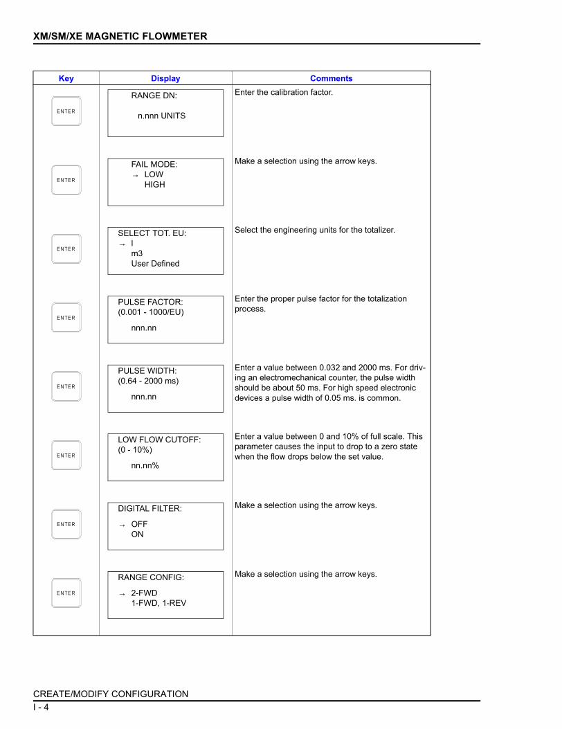
XM/SM/XE MAGNETIC FLOWMETER
Enter the calibration factor.
Make a selection using the arrow keys.
Select the engineering units for the totalizer.
Enter the proper pulse factor for the totalizationprocess.
Enter a value between 0.032 and 2000 ms. For driv-ing an electromechanical counter, the pulse width should be about 50 ms. For high speed electronic devices a pulse width of 0.05 ms. is common.
Enter a value between 0 and 10% of full scale. This parameter causes the input to drop to a zero state when the flow drops below the set value.
Make a selection using the arrow keys.
Make a selection using the arrow keys.
Key Display Comments
E N TE R
RANGE DN:
n.nnn UNITS
E N TE R
FAIL MODE:→ LOW
HIGH
E N TE R
SELECT TOT. EU:→ l
m3User Defined
E N TE R
PULSE FACTOR:(0.001 - 1000/EU)
nnn.nn
E N TE R
PULSE WIDTH:(0.64 - 2000 ms)
nnn.nn
E N TE R
LOW FLOW CUTOFF:(0 - 10%)
nn.nn%
E N TE R
DIGITAL FILTER:
→ OFFON
E N TE R
RANGE CONFIG:
→ 2-FWD1-FWD, 1-REV
CREATE/MODIFY CONFIGURATIONI - 4

XM/SM/XE MAGNETIC FLOWMETER
CALIBRATION
This section details the calibration functions of the STT04 terminalwhile interfacing an XM/SM/XE Mag Flow Meter. There are two typesof calibration functions:
• Empty pipe detector.• D-to-A adjust.
NOTES:1. When calibrating, a field device must be connected to theSTT04 terminal.
2. To change calibration or configuration parameters of a fielddevice that is connected to an IMFBS01 module, the transmittermust be taken off-line. This is done at the INFI 90 OPEN console.
Refer to Figure I-2 for an overview of the calibration functions.
Make a selection using the arrow keys.
Make a selection using the arrow keys.
Specify values using the number keys. The UNITS displayed will be those designated in a previous screen. After entering a value press .
Make a selection using the arrow keys.
Key Display Comments
E N TE R
FLOW DIRECTION:
→ FWD AND REVFWD ONLY
E N TE R
EMPTY PIPE DET.:
→ OFFON
E N TE R
UPPER PV ALARMnnn.nn UNITS
LOWER PV ALARMnnn.nn UNITS
ENTER
E N TE R
STORE THIS CONFIGURATION?
NO→ YES
E N TE R
ID TAGNAME
READY
CALIBRATION I - 5

XM/SM/XE MAGNETIC FLOWMETER
Empty Pipe Detector
This procedure applies to XM/SM/XE Mag Flow meters configured foreither ANALOG or DIGITAL. Any difference between the two arenoted in the Comments column.
Figure I-2. Calibration Flowchart (XM/SM/XE Mag Flow)
T01342A
D TO A A D JU S T
E M P T Y PIP E D E T E C TO R
A D JU S T TO 4 m A
A D JU S T F R E Q U E N C Y
VA L U E
E N T E R T H R E S H O LD
VA L U E
C A L IB R ATIO N C O M P LE T E
A D JU S T TO 2 0 m A
CALIBRATE
Key Display CommentsThis operation will cause a change in output not cor-responding to the input. Be sure the control loop is in manual.
Select YES.
Select EMPTY PIPE DET.If configured digitally, the D-TO-A ADJUST selection will not appear.
Use the arrow keys to adjust the frequency as described in the Mag-Flow product instruction. The frequency value will be updated between key presses, during which, a wait screen will appear.
Enter the threshold of the empty pipe detector with the number keys.
C A LI- B R ATE
OUTPUT WILL BEAFFECTED! PROCEED?
NO→ YES
E N TE R
CALIBRATIOND-TO-A ADJUST
→ EMPTY PIPE DET
E N TE R
FREQUENCYnnn.nn
E N TE R
THRESHOLD:nnn.nn Hz
CALIBRATIONI - 6

XM/SM/XE MAGNETIC FLOWMETER
D-to-A Adjust
The D-TO-A ADJUST selection is only present when you are in theANALOG communication mode, specified in the configuration proce-dure. This selection allows you to adjust the four to 20 milliampereoutput of the field device.
Empty pipe detector calibration is complete.Key Display Comments
E N TE R
ID TAGNAME
READY
Key Display CommentsThis operation will cause a change in output not cor-responding to the input. Be sure the control loop is in manual.
Select YES.
Select D-TO-A ADJUST.
Use the arrow keys to adjust the 4 mA signal.
NOTE: When increasing or decreasing the mA sig-nal, the increments of change increase with succes-sive depressions until the maximum level of change is reached. By changing direction you will return to the smallest increment of change. This adjustment technique speeds up the adjustment process without affecting fine adjustment.Use the arrow keys to adjust the 20 mA signal.
C A LI- B R ATE
OUTPUT WILL BEAFFECTED! PROCEED?
NO→ YES
E N TE R
CALIBRATION→ D-TO-A ADJUST
EMPTY PIPE DET
E N TE R
ADJUST TO 4 mA
THEN HIT ENTER
E N TE R
ADJUST TO 20 mA
THEN HIT ENTER
E N TE R
ID TAGNAME
READY
CALIBRATION I - 7

APPENDIX J - TBN480 CONDUCTIVITY TRANSMITTER
INTRODUCTION
This appendix covers the configuration and calibration functions ofthe TBN480 Conductivity Transmitter.
Refer to OPERATING PROCEDURES in Section 4 for information onthe following functions:
NOTE: To change calibration or configuration parameters of a smartfield device that is connected to an IMFBS01 module, the devicemust be taken off-line. This is done at the INFI 90 OPEN console.
CREATE/MODIFY CONFIGURATION
A configuration can be created off-line, without a connected fielddevice. Refer to Figure J-1 for an overview of the configurationfunction. The following table details the configuration process.
• Send configurations. • Select configurations.• Get configurations. • Erase configurations.• View configurations. • Operational functions.
Figure J-1. Configuration Flowchart (TBN480)
T 01 3 39A
C H O O SE A R A N G E JU M P E R
S E LE C T S E N S O R G R O U P
ID TAG S E LE C T M O D E
D IG ITA L
A N A LO G
E N T E R C H A N N E L N U M B E R
S E LE C T T R A N S M IT TE R
T Y P E
S E LE C T T E M P E R AT U R E
C O M P EN S AT IO N E F FE C T
S E LE C T D IAG S P IKE N O /Y E S
E N T E R DA M P IN G
C O N S TA N T
S AV E C O N F IG U R ATIO N
S E LE C T A N A LYZ E R
T Y P E
E N T E R L O W E R R A N G E VA L U E
E N T E R U P P E R R A N G E VA L U E
S E LE C T IN ITIA L IZ E
M O D E
S E LE C T FA IL M O D E
S E LE C T T E M P E R AT U R E
C O M P EN S AT IO N IN P U T
CONFI
GURE
INTRODUCTION J - 1

TBN480 CONDUCTIVITY TRANSMITTER
Key Display CommentsSelect NEW to create a new configuration. To modify an existing configuration, select MODIFY. The screen sequence is the same, however, the MODIFY screens will appear with the values and cursor posi-tions as originally configured.
Select ABB FSK.
Use the down arrow key to select TBN480 cond.
Enter a name for the configuration ID tag using up to 14 ASCII characters. To select a character, press the key that has the desired character. Continue to press the key until the desired character appears. Use the right arrow key to move to the next character. Use the left arrow key to go back to the previous charac-ter.Select ANALOG.
Select analyzer type.
C O N F IG
CONFIGURATION→ NEW
MODIFYERASE
E N TE R
DEVICE TYPE→ ABB FSK
HART
E N TE R
TRANSMITTER TYPEPTS EQSBCN EQNAVS → TB480 cond
E N TE R
STT04 CONFIGURATION[ ]
←PREVIOUS NEXT→
E N TE R
SELECT MODE:→ ANALOG
DIGITAL
E N TE R
ANALYZER TYPE→ GENERAL
PURE H2O CONDCONCENTRATION
CREATE/MODIFY CONFIGURATIONJ - 2
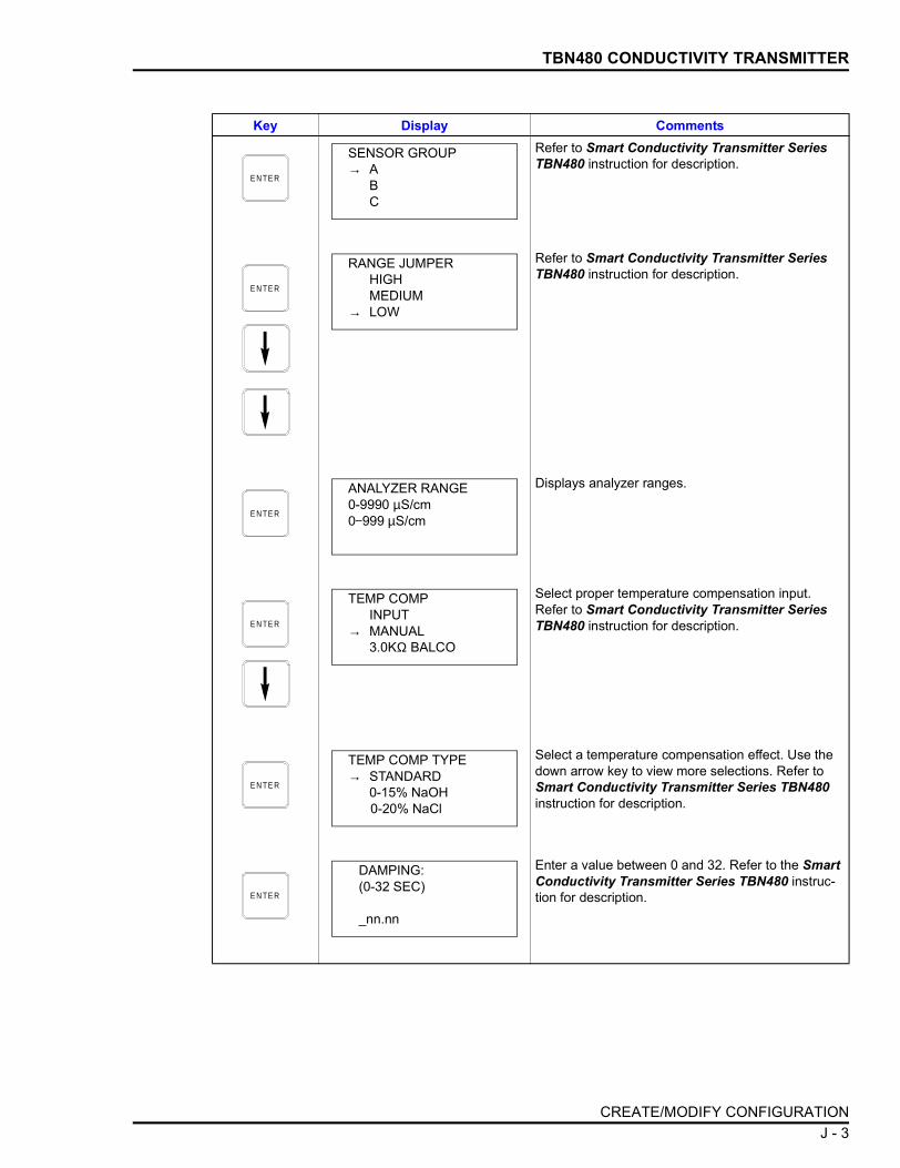
TBN480 CONDUCTIVITY TRANSMITTER
Refer to Smart Conductivity Transmitter Series TBN480 instruction for description.
Refer to Smart Conductivity Transmitter Series TBN480 instruction for description.
Displays analyzer ranges.
Select proper temperature compensation input. Refer to Smart Conductivity Transmitter Series TBN480 instruction for description.
Select a temperature compensation effect. Use the down arrow key to view more selections. Refer to Smart Conductivity Transmitter Series TBN480 instruction for description.
Enter a value between 0 and 32. Refer to the Smart Conductivity Transmitter Series TBN480 instruc-tion for description.
Key Display Comments
E N TE R
SENSOR GROUP→ A
BC
E N TE R
RANGE JUMPERHIGHMEDIUM
→ LOW
E N TE R
ANALYZER RANGE0-9990 µS/cm0−999 µS/cm
E N TE R
TEMP COMPINPUT
→ MANUAL3.0KΩ BALCO
E N TE R
TEMP COMP TYPE→ STANDARD
0-15% NaOH0-20% NaCl
E N TE R
DAMPING:(0-32 SEC)
_nn.nn
CREATE/MODIFY CONFIGURATION J - 3

TBN480 CONDUCTIVITY TRANSMITTER
Enter the lower range temperature value and press . Input the upper range value. Low and high
default values are dependent on the sensor group and range jumper setting. Refer to the Smart Con-ductivity Transmitter Series TBN480 instruction for description.
On power up, a two second initialization period occurs during which the transmitter output becomes either 100% (high) or 0% (low).
During continual diagnostics, if the microcomputer detects a fatal problem the transmitter output will go to 0% (low), 100% (high), or the last value before the error.
In analog mode, a pulse can be sent on the 4 to 20 mA output to indicate a detected sensor fault. This pulse can be adjusted from 0 to 100% of the loop current (0 to 16 mA).
Select YES to store the configuration.
Key Display Comments
E N TE R
LOWER RANGE VAL.nnn.nn µS/cm
UPPER RANGE VAL.nnn.nn µS/cm
ENTER
E N TE R
INITIALIZE MODE:LOW
→ HIGH
E N TE R
FAIL MODE:LOW
→ HIGHLAST
E N TE R
DIAG SPIKEOUTPUT→ NO
YES
E N TE R
STORE THIS CONFIGURATION
NO→ YES
E N TE R
ID TAGNAME
READY
CREATE/MODIFY CONFIGURATIONJ - 4

TBN480 CONDUCTIVITY TRANSMITTER
CALIBRATION
This section details the TBN480 conductivity transmitter calibrationfunctions using the STT04 terminal. There are three types of calibra-tion functions:
• Process.• Edit.• Reset.
NOTES:1. When calibrating, a field device must be connected to theSTT04 terminal.
2. To change calibration or configuration parameters of a fielddevice that is connected to an IMFBS01 module, the transmittermust be taken off-line. This is done at the INFI 90 OPEN console.
Refer to Figure J-1 for an overview of the calibration functions
Process Calibration
This procedure applies to TBN480 Transmitters configured for eitherANALOG or DIGITAL. Any differences between the two are noted inthe Comments column.
Figure J-2. Calibration Flowchart (TBN480)
T 01 3 38 A
A D JU S T TO D E S IR E D
C O N D U C T IV ITY
C A L IB R ATIO N C O M P LE T E
P R O C E S S
E D IT
R E S E T
C O N D U C T IV ITY
C O N D U C T IV ITY
R E S E T TO FAC TO RY
C O N F IG U R ATIO N
T E M P E R AT U R E
T E M P E R AT U R E
P R O C E S S T E M P E R AT U R E
C O R R E C T
E N T E R S L O P E A N D O F FS E T
C H A N G E T E M P E R AT U R E
F O R C A L IB R ATIO N
E N T E R S L O P E A N D O F FS E T
C A P T U R E AC T UA L
C O N D U C T IV ITY
CALIBRATE
CALIBRATION J - 5

TBN480 CONDUCTIVITY TRANSMITTER
CALIBRATE PROCESS CONDUCTIVITY
The following procedure steps through the calibration of the processconductivity.
Key Display CommentsThis operation will cause a change in output not cor-responding to the input. Be sure the control loop is in manual.
Select YES.
Select PROCESS CAL.
Select CONDUCTIVITY.
If the temperature value is not correct, go back and calibrate the process temperature before proceed-ing. Refer to Process Calibration in this section.
This displays the actual live reading. When the read-ing is stable press . The value displayed is captured for the next process calibration screen.
Use the numeric keys to correct the captured value to the desired value.
C A LI- B R ATE
OUTPUT WILL BEAFFECTED! PROCEED?
NO→ YES
E N TE R
CALIBRATION→ PROCESS CAL
EDIT CALRESET CAL
E N TE R
PROCESS CAL
→ CONDUCTIVITYTEMPERATURE
E N TE R
PROCESS TEMPnn.nn
CAL TEMP 1st IFINCORRECT
E N TE R
PROCESS CALnn.nn mS/cm
PRESS ENTER TO CONTINUE
ENTER
E N TE R
PROCESS CALENTER DESIREDCONDUCTIVITY
nn.nn mS/cm
E N TE RWORKING
CALIBRATIONJ - 6

TBN480 CONDUCTIVITY TRANSMITTER
CALIBRATE PROCESS TEMPERATURE
This section steps through calibrating the process temperature.
Calibration complete.
Key Display Comments
CALIBRATIONCOMPLETE
E N TE R
ID TAGNAME
READY
Key Display CommentsThis operation will cause a change in output not cor-responding to the input. Be sure the control loop is in manual.
Select YES.
Select PROCESS CAL.
Select TEMPERATURE.
C A LI- B R ATE
OUTPUT WILL BEAFFECTED! PROCEED?
NO→ YES
E N TE R
CALIBRATION→ PROCESS CAL
EDIT CALRESET CAL
E N TE R
PROCESS CAL
CONDUCTIVITY→ TEMPERATURE
CALIBRATION J - 7

TBN480 CONDUCTIVITY TRANSMITTER
Editing the Calibration Constants
These functions are for recording or modifying slope or offset calibra-tion constants.
EDIT CONDUCTIVITY
This procedure steps through the modification of the conductivity.
Use the numeric keys to enter the process temperature.
Key Display Comments
E N TE R
CHANGE TEMP FOR CALI-BRATION
nn.nn °C
E N TE RWORKING
CALIBRATIONCOMPLETE
E N TE R
ID TAGNAME
READY
Key Display CommentsThis operation will cause a change in output not cor-responding to the input. Be sure the control loop is in manual.
Select YES.
C A LI- B R ATE
OUTPUT WILL BEAFFECTED! PROCEED?
NO→ YES
CALIBRATIONJ - 8

TBN480 CONDUCTIVITY TRANSMITTER
EDIT TEMPERATURE
This procedure steps through modification of the temperature.
Select EDIT CAL.
Select CONDUCTIVITY.
To view values press twice.To change the slope enter the correct number and press .To change the offset, enter the correct number and press .
Key Display Comments
E N TE R
CALIBRATIONPROCESS CAL
→ EDIT CALRESET CAL
E N TE R
EDIT CAL DATA
→ CONDUCTIVITYTEMPERATURE
E N TE R
CONDUCTIVITYPROCESS CALSLP: n.nnnnOFF: n.nnnn
ENTER
ENTER
ENTER
E N TE RWORKING
CALIBRATIONCOMPLETE
E N TE R
ID TAGNAME
READY
CALIBRATION J - 9

TBN480 CONDUCTIVITY TRANSMITTER
Key Display CommentsThis operation will cause a change in output not cor-responding to the input. Be sure the control loop is in manual.
Select YES.
Select EDIT CAL.
Select TEMPERATURE.
To view values, press twice.To change the slope, enter the correct number and press .To change the offset, enter the correct number and press .
Calibration complete.
C A LI- B R ATE
OUTPUT WILL BEAFFECTED! PROCEED?
NO→ YES
E N TE R
CALIBRATIONPROCESS CAL
→ EDIT CALRESET CAL
E N TE R
EDIT CAL DATA
CONDUCTIVITY→ TEMPERATURE
E N TE R
TEMPERATUREPROCESS CALSLP: n.nnnnOFF:n.nnnn
ENTER
ENTER
ENTER
E N TE RWORKING
CALIBRATIONCOMPLETE
E N TE R
ID TAGNAME
READY
CALIBRATIONJ - 10

TBN480 CONDUCTIVITY TRANSMITTER
Reset to Factory Configuration
This function resets all of the device parameters to the factory set-tings. Refer to the product instruction for information on the factorysettings.
Key Display CommentsThis operation will cause a change in output not cor-responding to the input. Be sure the control loop is in manual.
Select YES.
Select RESET CAL.
C A LI- B R ATE
OUTPUT WILL BEAFFECTED! PROCEED?
NO→ YES
E N TE R
CALIBRATIONPROCESS CALEDIT CAL
→ RESET CAL
E N TE RWORKING
CALIBRATIONCOMPLETE
ID TAGNAME
READY
CALIBRATION J - 11

APPENDIX K - TBN580 TRANSMITTER
INTRODUCTION
This appendix covers the configuration and calibration functions ofthe TBN580 Transmitter. Refer to OPERATING PROCEDURES inSection 4 for information on the following functions:
NOTE: To change calibration or configuration parameters of a smartfield device that is connected to an IMFBS01 module, the devicemust be taken off-line. This is done at the INFI 90 OPEN console.
CREATE/MODIFY CONFIGURATION
A configuration can be created off-line, without a connected fielddevice. Refer to Figure K-1 for an overview of the configuration func-tion of the TBN580 pH transmitter. The following table details the con-figuration process.
• Send configurations. • Select configurations.• Get configurations. • Erase configurations.• View configurations. • Operational functions.
Figure K-1. Configuration Flowchart (TBN580)
T 01 33 7 A
S ELE C T TE M PE RATUR E
CO M P E NSATIO N TY P E
S ELE CT M O D E
E NTE R C H A N N E L N U M B ER
S ELE C T FA IL M O D E
D IG ITA L
A N A LO G S ELE C T TR A N S M ITTE R
TY P E
S ELE C T OU TPU T AC TIO N
S ELE C T TE M PE R ATU RE D IS PLAY U NITS
S PE C IFY FU N C T ION
G E NE R ATO R
S ELE C T IN IT IA L IZE
M O DE
S ELE C T pH S EN S O R IN PU T
E N TE R DA M PING
C O NSTAN T
S AVE C O N FIGU R ATIO N
E N TE R LOW E R R A N GE VA LU E
E NTE R S EC O NDA RY
LOW E R /U P PE R R A N G E VA LUE S
E N TE R S EC O NDA RY
U N ITS
E N TE R S O LUTIO N
CO EFF IC IEN T
CONFI
GURE
S ELE C T TE M PE RATU R E
CO M P E NSATIO N INP U T
E N TE R U PP E R RA N G E VA LU E
INTRODUCTION K - 1

TBN580 TRANSMITTER
Key Display CommentsTo create a new configuration, select NEW. To mod-ify an existing configuration, select MODIFY. The screen sequence is the same, however, the MODIFY screens will appear with the values and cursor posi-tions as originally configured.
Select ABB FSK as device type.
Use the down arrow key and select TB580 pH.
Enter a name for the configuration ID tag using up to 14 ASCII characters. To select a character, press the key that has the desired character. Continue to press the key until the desired character appears. Use the right arrow key to move to the next character. Use the left arrow key to go back to the previous charac-ter.Select ANALOG.
For this example, select STANDARD.
STANDARD: thermo-isopotential 7.0 pH;slope 59.15 mV at 25°C.ANTIMONY: isopotential 1.5 pH; slope 51 mVat 25°C.
NOTE: If after selecting ANTIMONY, the STT04 ter-minal branches to a TEMPERATURE DISPLAY UNITS selection screen, choose the desired temper-ature unit.
C O N F IG
CONFIGURATION→ NEW
MODIFYERASE
E N TE R
DEVICE TYPE
→ ABB FSKHART
E N TE R
TRANSMITTER TYPEBCN EQNAVS TB480 cond
→ TB580 pH TB581 ORP
E N TE R
STT04 CONFIGURATION[ ]
←PREVIOUS NEXT→
E N TE R
SELECT MODE:→ ANALOG
DIGITAL
E N TE R
pH SENSOR INPUT→ STANDARD
ANTIMONY
CREATE/MODIFY CONFIGURATIONK - 2

TBN580 TRANSMITTER
Select 3.01 K BALCO.
When NONE is selected, the STT04 terminal branches to a TEMPERATURE DISPLAY UNITS selection screen. Choose the desired temperature unit.
For this example select AUTO SOLUTION.
NOTE: Other temperature compensation selections branch to a TEMPERATURE DISPLAY UNITS selec-tion screen.
This screen is unique to the AUTO SOLUTION selection of the TEMP COMP TYPE. Otherselections go to the temperature display units.
Select NO.
If YES is selected, enter 5 input and output points. Values must be between 0 and 100%.
Refer to the Smart Specific Ion Transmitter Series TBN580 instruction for description.
Enter a value between 0 and 32. Refer to the Smart Specific Ion Transmitter Series TBN580 instruction for description.
Key Display Comments
E N TE R
TEMP COMP INPUT→ 3.01 K BALCO
NONE
E N TE R
TEMP COMP TYPEMANUALAUTO NERNSTIAN
→ AUTO SOLUTIONAUTO PURE H2O
E N TE R
ENTER SOLUTIONCO-EFFICIENT±n.nnn pH per
10°C (from 25°C)
E N TE R
TEMPERATUREDISPLAY UNITS→ °C
°F
E N TE R
OUTPUT FUNC GEN→ NO
YES
E N TE R
OUTPUT ACTION:→ NORMAL
REVERSE
E N TE R
DAMPING:(0-32 SEC)
_nn.nn
CREATE/MODIFY CONFIGURATION K - 3

TBN580 TRANSMITTER
Enter the lower range value and press . Input the upper range value.
Refer to the Smart Specific Ion Transmitter Series TBN580 instruction for description.
During continual diagnostics, if the microcomputer detects a fatal problem the transmitter output will go to 0% (low), 100% (high), or the last value before the error.
Enter up to 6 characters. Use familiar units to describe the output.
Input the lower range value and press . Input the upper range value.
To store the configuration, select YES.
Key Display Comments
E N TE R
LOWER RANGE VAL._nn.nn pH
UPPER RANGE VAL.nn.nn pH
ENTER
E N TE R
INITIALIZE MODE:→ LOW
HIGH
E N TE R
FAIL MODE:→ LOW
HIGHLAST
E N TE R
ENTERSECONDARY UNITS _nnnnnn
E N TE R
SECONDARY L.R._nn.nn UNITS
SECONDARY U.R.nn.nn UNITS
ENTER
E N TE R
STORE THIS CONFIGURATION
NO→ YES
E N TE R
ID TAGNAME
READY
CREATE/MODIFY CONFIGURATIONK - 4

TBN580 TRANSMITTER
CALIBRATION
This section details the calibration functions of the STT04 terminalwhile interfacing a TBN transmitter. There are three types of calibra-tion functions:
• Process calibration.• Bench calibration (pH and temperature).• D-to-A adjust.
NOTES:1. When calibrating, a field device must be connected to theSTT04 terminal.
2. To change calibration or configuration parameters of a fielddevice that is connected to an IMFBS01 module, the transmittermust be taken off-line. This is done at the INFI 90 OPEN console.
Refer to Figure K-2 for an overview of the calibration functions.
Figure K-2. Calibration Flowchart (TBN580)
T 013 36 A
E N TE R pH O F P RO C ES S
A PP LY L O W /H IG H pH VA L UE S
E N TE R LO W /H IG H pH VA LU E S
C A LIBR ATIO N C O M P LE TE
P RO C ES S
B EN C H (pH )
B ENC H (TE M P)
N E W S E N SO R
IN P U T S O U R CE
E N TE R FIX ED P RO C ES S
TE M PE R ATUR E
TE M PE RATU RE C O M P E N SATIO N
TY P E
S AM E O R N E W S ENS O R
m V S O U R C E
C H A N G E pH C A LIBR ATIO N
TE M PE R ATUR E
TE M PE R ATUR E C O M P E N SATIO N
TY P E
E NTE R LO W /H IG H
m V VA LU ES
C A LC UL AT ED E FF IC IE N C Y
C A LC UL AT ED S EN S O R O F FS ET
CU M U LATIV E O F FS ET CH A N G E
CALIBRATE
C H A N G E E FFIC IE NC Y
C HA N G E p H CA LIBRATIO N
TE M PE R ATU R E
A PP LY L O W /H IG H
m V VA LU ES
CALIBRATION K - 5

TBN580 TRANSMITTER
Process Calibration
This procedure applies to TBN transmitters configured for either ANA-LOG or DIGITAL. Any differences between the two are noted in theComments column.
Key Display CommentsSelect YES.
Select PROCESS CAL.
If configured digitally, the D-TO-A ADJUST selection would not appear.
Select NO.
If YES, a new sensor offset will be calculated and the cumulative offset change will be reset to 0.00 mV.
Displayed will be the TEMP COMP TYPE selected in configuration.
If TEMP COMP TYPE is MANUAL or NONE (as selected in configuration), this screen will appear, otherwise, the next screen, CHANGE TEMP OF PROCESS? will appear. Default is 25°C.
The value displayed is the temperature of the pro-cess (interior of sensor).
NOTE: If the new temperature value is entered, this change will affect the calibration of temperature.
C A LI- B R ATE
OUTPUT WILL BEAFFECTED! PROCEED?
NO→ YES
E N TE R
CALIBRATION→ PROCESS CAL
BENCH CAL pHBENCH CAL TEMPD-TO-A ADJUST
E N TE R
INSTALLING ANEW SENSOR?→ NO
YES
E N TE R
TEMP COMP TYPEIN USE:
HIT ENTER
E N TE R
ENTER FIXED PROCESS TEMP
nnn.n°UNITS
E N TE R
CHANGE TEMPOF PROCESS?
nnn°UNITS
CALIBRATIONK - 6

TBN580 TRANSMITTER
Bench Calibration pH
The following procedure steps through the bench calibration of the pHlevel.
Value from last calibration. If NEW SENSOR, effi-ciency will be 98%. This value can be changed if desired. A change in efficiency will affect the calibra-tion span.
The current PH value is displayed. Enter the desired PH value.
This value is recalculated during each calibration.
This value shows the offset change over time for a particular sensor. Value resets to 0.00 pH if installing a new sensor.
Key Display Comments
E N TE R
CHANGEEFFICIENCY?
nn.nn% HIT ENTER
E N TE R
CURRENT READINGnn.nn pH
ENTER DESIREDnn.nn pH
E N TE R
CALCULATED EFFICIENCY
nnn.nn%HIT ENTER
E N TE R
CALCULATED SENSOR OFFSET
nnn.nn pHHIT ENTER
E N TE R
CUMULATIVEOFFSET CHANGE
n.nn pHHIT ENTER
E N TE R
ID TAGNAME
READY
CALIBRATION K - 7

TBN580 TRANSMITTER
Key Display CommentsThis operation will cause a change in output not cor-responding to the input. Be sure the control loop is in manual.
Select YES.
Select BENCH CAL pH.
Select mV SOURCE.When selecting SAME SENSOR or NEW SENSOR, the smart terminal branches to TEMP COMP TYPE IN USE.
The following mV screens apply only when mV SOURCE is selected under INPUT SOURCE.
NOTE: Positive mV corresponds to low pH values and negative mV corresponds to high pH values.
Default values are ±414 mV.Positive mV cal value specified on the prior screen will be displayed. Apply low mV value. When applied, the value shown on the smart terminal (from the input source) will not match the specified value. Press when the applied value stabilizes.
Negative mV cal value specified on the prior screen will be displayed. Apply high mV value. When applied, the value shown on the smart terminal (from the input source) will not match the specified value. Press when the applied value stabilizes. When mV operation is complete press , the READY screen will follow.
C A LI- B R ATE
OUTPUT WILL BEAFFECTED! PROCEED?
NO→ YES
E N TE R
CALIBRATIONPROCESS CAL
→ BENCH CAL pHBENCH CAL TEMP
E N TE R
INPUT SOURCE:SAME SENSORNEW SENSOR
→ mV SOURCE
E N TE R
ENTER LO mV CALnn.nn mV
ENTER HI mV CALnn.nn mV
E N TE R
APPLY nn.nn mVnn.nn
HIT ENTER WHEN STABLE
ENTER
E N TE R
APPLY nn.nn mVnn.nn
HIT ENTERWHEN STABLE
ENTERENTER
CALIBRATIONK - 8

TBN580 TRANSMITTER
The value displayed is the temperature of the pro-cess (interior of sensor). Default is 25°C.
NOTE: If a new temperature value is entered, it is used only for pH calibration. This change does not affect the calibration on the temperature sensor.
Default values 4.01 and 7.00 pH. Enter low pH value and press . Enter the high pH value. If mV SOURCE, default is 0.00 and 14.00 pH at 25°C.
Displays low pH calibration value, and the uncali-brated pH value as determined from the input source.
Displays high pH calibration value, and the uncali-brated pH value as determined from the input source.
Value from the last calibration. If NEW SENSOR effi-ciency will be 98%.
This value is recalculated during each calibration.
This value shows the offset change over time for a particular sensor. Value resets to 0.00 pH if installing a new sensor.
Key Display Comments
E N TE R
CHANGE pH CALTEMPERATURE?
nnn°UNITS
E N TE R
ENTER LO pH CALnn.nn pH
ENTER HI pH CALnn.nn pH
ENTER
E N TE R
APPLY nn.nn pHnn.nn pH
HIT ENTERWHEN STABLE
E N TE R
APPLY nn.nn pHnn.nn pH
HIT ENTERWHEN STABLE
E N TE R
CALCULATEDEFFICIENCY
nnn.n %HIT ENTER
E N TE R
CALCULATEDSENSOR OFFSET
nnn pHHIT ENTER
E N TE R
CUMULATIVEOFFSET CHANGE
nnn pHHIT ENTER
E N TE R
ID TAGNAME
READY
CALIBRATION K - 9

TBN580 TRANSMITTER
Bench Calibration Temperature
The following procedure steps through the bench calibration of thetemperature.
Key Display CommentsThis operation will cause a change in output not cor-responding to the input. Be sure the control loop is in manual.
Select YES.
Select BENCH CAL TEMP.
If in TEMP COMP TYPE, MANUAL or NONE is selected during configuration, this screen will not appear, otherwise the next screen, CHANGE TEMP OF PROCESS? appears. Default is 25°C.
The value displayed is the temperature of the pro-cess (interior of sensor).
NOTE: If a new temperature value is entered, this change will affect the calibration of temperature.
C A LI- B R ATE
OUTPUT WILL BEAFFECTED! PROCEED?
NO→ YES
E N TE R
CALIBRATIONPROCESS CALBENCH CAL pH
→ BENCH CAL TEMP
E N TE R
ENTER FIXED PROCESS TEMP
nnn.n° UNITS
E N TE R
CHANGE TEMPOF PROCESS?nnn.n° UNITS
E N TE R
ID TAGNAME
READY
CALIBRATIONK - 10

TBN580 TRANSMITTER
D-to-A Adjust
The D-TO-A ADJUST selection is only present when you are in theANALOG communication mode, specified in the configuration proce-dure. This selection allows you to adjust the four to 20 milliampereoutput of the field device.
Key Display CommentsThis operation will cause a change in output not cor-responding to the input. Be sure the control loop is in manual.
Select YES.
Select D-TO-A ADJUST.
Use the arrow keys to adjust the 4 mA signal.
NOTE: When increasing or decreasing the mA sig-nal, the increments of change increase with succes-sive depressions until the maximum level of change is reached. By changing direction you will return to the smallest increment of change. This adjustment technique speeds up the adjustment process without affecting fine adjustment.Use the arrow keys to adjust the 20 mA signal.
C A LI- B R ATE
OUTPUT WILL BEAFFECTED! PROCEED?
NO→ YES
E N TE R
CALIBRATIONPROCESS CALBENCH CAL pHBENCH CAL TEMP
→ D-TO-A ADJUST
E N TE R
ADJUST TO 4 mA
THEN HIT ENTER
E N TE R
ADJUST TO 20 mA
THEN HIT ENTER
CALIBRATION K - 11

TBN580 TRANSMITTER
Key Display Comments
E N TE R
ID TAGNAME
READY
CALIBRATIONK - 12
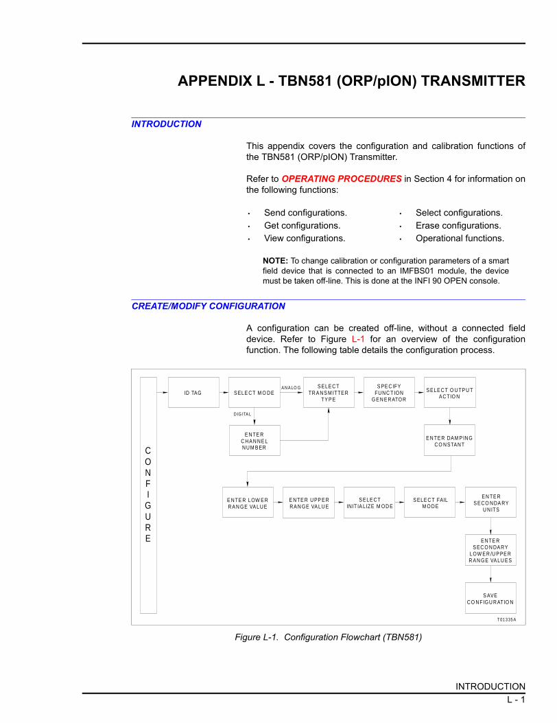
APPENDIX L - TBN581 (ORP/pION) TRANSMITTER
INTRODUCTION
This appendix covers the configuration and calibration functions ofthe TBN581 (ORP/pION) Transmitter.
Refer to OPERATING PROCEDURES in Section 4 for information onthe following functions:
NOTE: To change calibration or configuration parameters of a smartfield device that is connected to an IMFBS01 module, the devicemust be taken off-line. This is done at the INFI 90 OPEN console.
CREATE/MODIFY CONFIGURATION
A configuration can be created off-line, without a connected fielddevice. Refer to Figure L-1 for an overview of the configurationfunction. The following table details the configuration process.
• Send configurations. • Select configurations.• Get configurations. • Erase configurations.• View configurations. • Operational functions.
Figure L-1. Configuration Flowchart (TBN581)
T 01 3 35 A
E N TE R DAM P IN G C O N STAN T
E N TE R LOW E R R A N GE VA L U E
ID TAG S ELE C T M O D ES ELE C T
TR A N S M ITTE R T Y P E
S PE C IFY FU N C T ION
G E N E R ATO R
E N TE R U PP E R R A N GE VA LU E
E N TE R C H A N N E L N U M B ER
D IG ITA L
A N A LO G
S ELE C T IN IT IA L IZE M OD E
S ELE C T FAIL M O D E
E N TE R S EC O N DA RY
U N ITS
E N TE R S EC O N DA RY
LOW E R /U P PE R R A N GE VA LU E S
S AVE C O N FIGU R ATIO N
CONFIGURE
S ELE C T O U TP U T AC TIO N
INTRODUCTION L - 1

TBN581 (ORP/pION) TRANSMITTER
Key Display CommentsSelect NEW. To modify an existing configuration, select MODIFY. The screen sequence is the same, however, the MODIFY screens appear with the val-ues and cursor positions as originally configured.
Select ABB FSK as device type.
Use the down arrow key and select TB581 ORP.
Enter a name for the configuration ID tag using up to 14 ASCII characters. To select a character, press the key that has the desired character. Continue to press the key until the desired character appears. Use the right arrow key to move to the next character. Use the left arrow key to go back to the previous charac-ter.Select ANALOG.
C O N F IG
CONFIGURATION→ NEW
MODIFYERASE
E N TE R
DEVICE TYPE
→ ABB FSKHART
E N TE R
TRANSMITTER TYPEBCN EQNAVS TB480 condTB580 pH → TB581 ORP
E N TE R
STT04 CONFIGURATION[ ]
←PREVIOUS NEXT→
E N TE R
SELECT MODE:→ ANALOG
DIGITAL
CREATE/MODIFY CONFIGURATIONL - 2

TBN581 (ORP/pION) TRANSMITTER
Select ORP/pION.
Select NO.
If YES is selected enter 5 input and output points. Values must be between 0 and 100%.
Refer to Smart (ORP/pION) Transmitter Series TBN581 instruction for description.
Enter a value between 0 and 32. Refer to the Smart (ORP/pION) Transmitter Series TBN581 instruction for description.
Enter the lower range temperature value and press . Input the upper range value.
Low default value: -1000 mV.High default value: +1000 mV.
Refer to the Smart (ORP/pION) Transmitter Series TBN581 instruction for description.
Refer to the Smart (ORP/pION) Transmitter Series TBN581 instruction for description.
Key Display Comments
E N TE R
TRANSMITTER TYPE cond TBNpH TBN
→ ORP/pION
E N TE R
OUTPUT FUNC GEN→ NO
YES
E N TE R
OUTPUT ACTION:→ NORMAL
REVERSE
E N TE R
DAMPING:(0-32 SEC)
_nn.nn
E N TE R
LOWER RANGE VALnnn.nn mV
UPPER RANGE VALnnn.nn mV
ENTER
E N TE R
INITIALIZE MODE:→ LOW
HIGH
E N TE R
FAIL MODE:→ LOW
HIGHLAST
CREATE/MODIFY CONFIGURATION L - 3

TBN581 (ORP/pION) TRANSMITTER
CALIBRATION
This section details the calibration functions of the STT04 terminalwhile interfacing a TBN581 ORP/pION transmitter. There are fourtypes of calibration functions:
• Process calibration.• Bench calibration (ORP/pION).• Bench calibration (mV).• D-to-A adjust.
NOTES:1. When calibrating, a field device must be connected to theSTT04 terminal.
2. To change calibration or configuration parameters of a fielddevice that is connected to an IMFBS01 module, the transmittermust be taken off-line. This is done at the INFI 90 OPEN console.
Refer to Figure L-2 for an overview of the calibration functions.
Enter up to 6 characters. Use familiar units to describe the output.
Input the lower range value and press . Input the upper range value.
Select YES to store the configuration.
The Configuration ID tag name just configured will be in the upper left corner if the configuration is saved. It becomes the working configuration.
NOTE: Connect the terminal to a device and send the configuration (using ) to a device before calibrating.
Key Display Comments
E N TE R
ENTERSECONDARY UNITS_nnnnnn
E N TE R
SECONDARY L.R._nn.nn UNITS
SECONDARY U.R.nn.nn UNITS
ENTER
E N TE R
STORE THIS CONFIGURATION
NO→ YES
E N TE R
ID TAGNAME
READY
SEND CONFIG
CALIBRATIONL - 4

TBN581 (ORP/pION) TRANSMITTER
Process Calibration
This procedure applies to TBN581 Transmitters configured for eitherANALOG or DIGITAL. Any differences between the two are noted inthe Comments column.
Figure L-2. Calibration Flowchart (TBN581)
T 01 3 34 A
C U M U LAT IV E O F F S ET C H A N G E
P R O C E S S
B E N C H
N E W S E N S O R
IN P U T S O U R C E
E N T E R N E W D E S IR E D R E A D IN G
S A M E O R N E W S E N S O R
m V S O U R C E
C A L C U LATE D E F FIC IE N C Y
E N T E R L OW /H IG H m V
VA L U E S
E N T E R L OW /H IG H m V
VA L U E S
C A L IB R ATIO N C O M P LE T E
CALIBRATE
C A L C U LATE D S E N S O R O F F S ET
A P P LY L OW /H IG H m V
VA L U E S
A P P LY L OW /H IG H
m V VA L U E S
Key Display CommentsThis operation will cause a change in output not cor-responding to the input. Be sure the control loop is in manual.
Select YES.
Select PROCESS CAL. If configured digitally, the D-TO-A ADJUST selection would not appear.
Select NO.
If YES, a new sensor offset will be calculated and the CUMULATIVE OFFSET CHANGE will be reset to 0.00 mV.
C A LI- B R ATE
OUTPUT WILL BEAFFECTED! PROCEED?
NO→ YES
E N TE R
CALIBRATION→ PROCESS CAL
BENCH CALD-TO-A ADJUST
E N TE R
INSTALLING ANEW SENSOR?→ NO
YES
CALIBRATION L - 5

TBN581 (ORP/pION) TRANSMITTER
Bench Calibration (ORP/pION)
This procedure applies to TBN581 Transmitters configured for eitherANALOG or DIGITAL. Any differences between the two are noted inthe Comments column.
Value from last calibration. If NEW SENSOR, effi-ciency will be 98%. This value can be changed if desired. A change in efficiency will affect calibration span.
This value is recalculated during each calibration.
This value shows the offset change over time for a particular sensor. Value resets to 0.00 pH if installing a new sensor.
Key Display Comments
E N TE R
CHANGEEFFICIENCY?
nn.nn%HIT ENTER
E N TE R
CURRENT READINGnn.nn mV
ENTER DESIREDnn.nn mV
E N TE R
CALCULATED SENSOR OFFSET
nnn.nn pHHIT ENTER
E N TE R
CUMULATIVEOFFSET CHANGE
n.nn pHHIT ENTER
E N TE R
ID TAGNAME
READY
Key Display CommentsThis operation will cause a change in output not cor-responding to the input. Be sure the control loop is in manual.
Select YES.
C A LI- B R ATE
OUTPUT WILL BEAFFECTED! PROCEED?
NO→ YES
CALIBRATIONL - 6

TBN581 (ORP/pION) TRANSMITTER
Select BENCH CAL.
SAME SENSOR:CALCULATED SENSOR OFFSET, CALCULATED EFFICIENCY, and CUMULATIVE OFFSET CHANGE are recalculated.
NEW SENSOR: CALCULATED SENSOR OFFSET, CALCULATED EFFICIENCY are calculated and CUMULATIVE OFFSET CHANGE is set to 0.00 mV.
NOTE: mV SOURCE selection is covered in Bench Calibration (mV).Low default value: -1000 mV.High default value: +1000 mV.Enter low mV value and press . Enter high mV value.
Displays low mV calibration value, and the uncali-brated mV values determined from the input source.
Displays high mV calibration value, and the uncali-brated mV values determined from the input source.
Value from last calibration. If new sensor, efficiency will be 98%.
This value is recalculated during each calibration.
Key Display Comments
E N TE R
CALIBRATIONPROCESS CAL
→ BENCH CAL D-TO-A ADJUST
E N TE R
INPUT SOURCE:→ SAME SENSOR
NEW SENSORmV SOURCE
E N TE R
ENTER LO mV CALnn.nn mV
ENTER HI mV CALnn.nn mV
ENTER
E N TE R
APPLY nn.nn mVnn.nn
HIT ENTER WHEN STABLE
E N TE R
APPLY nn.nn mVnn.nn
HIT ENTERWHEN STABLE
E N TE R
CALCULATEDEFFICIENCY
nnn.n %HIT ENTER
E N TE R
CALCULATEDSENSOR OFFSET
nnn pHHIT ENTER
CALIBRATION L - 7

TBN581 (ORP/pION) TRANSMITTER
Bench Calibration (mV)
This procedure applies to TBN581 Transmitters configured for eitherANALOG or DIGITAL. Any difference between the two are noted inthe Comments column.
This value shows the offset change over time for a particular sensor. Value resets to 0.00 mV if installing a new sensor.
Calibration complete.
Key Display Comments
E N TE R
CUMULATIVEOFFSET CHANGE
nnn pHHIT ENTER
E N TE R
ID TAGNAME
READY
Key Display CommentsThis operation will cause a change in output not cor-responding to the input. Be sure the control loop is in manual.
Select YES.
Select BENCH CAL.
Select mV SOURCE.
Low default value: -1000 mV.High default value: +1000 mV.Enter low mV value and press . Enter high mV value.
C A LI- B R ATE
OUTPUT WILL BEAFFECTED! PROCEED?
NO→ YES
E N TE R
CALIBRATIONPROCESS CAL
→ BENCH CALD-TO-A ADJUST
E N TE R
INPUT SOURCE:SAME SENSORNEW SENSOR
→ mV SOURCE
E N TE R
ENTER LO mV CALnn.nn mV
ENTER HI mV CALnn.nn mV
ENTER
CALIBRATIONL - 8

TBN581 (ORP/pION) TRANSMITTER
D-to-A Adjust
The D-TO-A ADJUST selection is only present when you are in theANALOG communication mode, specified in the configuration proce-dure. This selection allows you to adjust the four to 20 milliampereoutput of the field device.
Displays low mV calibration value, and the uncali-brated mV values determined from the input source.
Displays high mV calibration value, and the uncali-brated mV values determined from the input source.
Key Display Comments
E N TE R
APPLY nn.nn mVnn.nn mV
HIT ENTER WHEN STABLE
E N TE R
APPLY nn.nn mVnn.nn mV
HIT ENTERWHEN STABLE
E N TE R
ID TAGNAME
READY
Key Display CommentsThis operation will cause a change in output not cor-responding to the input. Be sure the control loop is in manual.
Select YES.
Select D-TO-A ADJUST.
Use the arrow keys to adjust the 4 mA signal.
NOTE: When increasing or decreasing the mA sig-nal, the increments of change increase with succes-sive depressions until the maximum level of change is reached. By changing direction you will return to the smallest increment of change. This adjustment technique speeds up the adjustment process without affecting fine adjustment.
C A LI- B R ATE
OUTPUT WILL BEAFFECTED! PROCEED?
NO→ YES
E N TE R
CALIBRATION→ D-TO-A ADJUST
BENCH CALIB.
E N TE R
ADJUST TO 4 mA
THEN HIT ENTER
CALIBRATION L - 9

TBN581 (ORP/pION) TRANSMITTER
Use the arrow keys to adjust the 20 mA signal.Key Display Comments
E N TE R
ADJUST TO 20 mA
THEN HIT ENTER
E N TE R
ID TAGNAME
READY
CALIBRATIONL - 10

APPENDIX M - TZID/AZH POSITIONER
INTRODUCTION
This appendix covers the configuration, calibration and special fea-ture functions of the TZID/AZH Positioner. Table M-1 lists the errorand problem codes of the TZID/AZH positioner.
Refer to OPERATING PROCEDURES in Section 4 for information onthe following functions:
CREATE/MODIFY CONFIGURATION
A configuration can be created off-line, without a connected fielddevice. Refer to Figure M-1 for an overview of the configurationfunction. The following table details the configuration process.
• Send configurations. • Select configurations.• Get configurations. • Erase configurations.• View configurations. • Operational functions.
Figure M-1. Configuration Flowchart (TZID/AZH)
T02395A
D E V IC ETY P E
E N T E RD E S C R IP TO R
C H A R AC TE R IS TICC U RV E
A D JU S T T IM EU P A N D D OW N
C O N F IG U R ATIO NN A M E
E N TE RDATE
E N TE RD E A D B A N D
VA LU E
S AV EC O N F IG U R ATIO N
TAGN U M B E R
E N T E R L OWS E T P O IN T
R A N G E
E N TE RS H U T-O FF VA LV E
P E R C E N TAG E
TR A N S M ITTE RT Y P E
P O S IT IO N IN GTA S K
S E LE C TVA LV E AC T IO N
E N TE RLO W A N D H IG HA L A R M LIM ITS
S E LE C TM O D E
S E LE C TS E T P O IN T
U N ITS
E N TE RM IN A N D M A X
S TRO K E VA LU E
E N T E R H IG HS E T P O IN T
R A N G E
E N TE RD E A D B A N DTIM E LIM IT
CONFI
GURE
INTRODUCTION M - 1

TZID/AZH POSITIONER
Key Display CommentsSelect NEW to create a configuration. To modify an existing configuration, select MODIFY. The screen sequence is the same, however, the MODIFY screens will appear with the values and arrow posi-tions as they were originally configured.
Select HART.
Select TZID/AZH.
Enter a name for the configuration ID tag using up to 8 ASCII characters. To select a character, press the key that has the desired character. Continue to press the key until the desired character appears. Use the right arrow key to move to the next character. Use the left arrow key to go back to the previous charac-ter.Select ANALOG.
NOTE: The DIGITAL selection should only be made when using the device in multidrop mode. A CHAN-NEL # prompt appears when DIGITAL is selected.
Enter up to 32 characters (ASCII) of descriptive text in this field.
C O N F IG
CONFIGURATION→ NEW
MODIFYERASE
E N TE R
DEVICE TYPE
ABB FSK→ HART
E N TE R
TRANSMITTER TYPETB82 pH TB82 ORPTB82 pION TB82 CONC
→ TZID/AZH HART UNIV
E N TE R
STT04 CONFIGURATION[ ]
←PREVIOUS NEXT→
E N TE R
SELECT MODE: → ANALOG
DIGITAL
E N TE R
TAG NUMBER
←PREVIOUS NEXT→
CREATE/MODIFY CONFIGURATIONM - 2

TZID/AZH POSITIONER
Type a descriptor string using up to 16 characters. This field can be used for notations about the device or process.
To select a character, press the key that has the desired character. Continue to press the key until the desired character appears. Use the right arrow key to move to the next character. Use the left arrow key to go back to the previous character.Enter up to 32 characters to describe the positioning task.
Enter a day and press . Enter a month and press . Enter a year and press .
This date can represent the creation date of the con-figuration, the date the device or element was installed, or some other significant date.
Select mA.
Enter the low set point and press . Enter the high set point.
Additional selections include EQUAL% 25:1 and EQUAL% 50:1 and USER DEFINED.
USER DEFINED is present only if a characteristic curve had been previously defined. Refer to SPE-CIAL FEATURE in this section for details about defining a characteristic curve.Represents the relationship between input current and movement of the valve.
Defines the accuracy with which the valve position is corrected to reach the set point. If control deviation is smaller than the value defined by the deadband, no further correction occurs, and the air output is set to the neutral position.
Key Display Comments
E N TE R
DESCRIPTOR:
←PREVIOUS NEXT→
E N TE R
POSITIONING TASK:_
←PREVIOUS NEXT→
E N TE R
DATE:DAY: nnMONTH: nnYEAR: nnnn
ENTERENTER ENTER
E N TE R
SET-POINT UNITS→ mA
%
E N TE R
LOW SET-POINT RANGE4.00 mA
HIGH SET-POINT RANGE20.00 mA
ENTER
E N TE R
CHARACTERISTIC CURVE→ LINEAR
EQUAL % 1:25EQUAL % 1:50
E N TE R
VALVE ACTION→ DIRECT
REVERSE
E N TE R
DEADBAND(0 - 10%)
0.00%
CREATE/MODIFY CONFIGURATION M - 3

TZID/AZH POSITIONER
Use the stroke range to further reduce the valve range given by the valve stops.
A percentage of the input current where the zero point occurs.
Monitors the control deviation. If the valve can not be positioned correctly within the deadband time limit, an error message is generated.
Specify time using the number keypad. This parame-ter provides electronic damping of the valve stroke movement and limits stroke speed to the specified value.
Low and high alarm limits are user configurable alarms.
NOTE: Use to return to a previous configura-tion screen from any screen in the configuration pro-cess.
Select YES.
Key Display Comments
E N TE R
MIN STROKE RANGE:0.00 %
MAX STROKE RANGE:100.00 %
E N TE R
SHUT-OFF VALUE(0 - 20 %)
nn.nn %
E N TE R
DEADBAND TIME LIMIT(0 - 200 sec)
n.nn sec
E N TE R
ADJUSTED TIME, UPnn.nn sec
ADJUSTED TIME, DOWNnn.nn sec
E N TE R
LOW ALARM LIMITnn.nn %
HIGH ALARM LIMITnn.nn % BACK
E N TE R
STORE THIS CONFIGURATION?
NO→ YES
E N TE R
ID TAGNAME
READY
CREATE/MODIFY CONFIGURATIONM - 4

TZID/AZH POSITIONER
CALIBRATION
This section details the TZID/AZH positioner calibration functionsusing an STT04 terminal.
NOTE: When calibrating, a field device must be connected to theSTT04 terminal.
Refer to Figure M-2 for an overview of the calibration functions.
Autostroke Calibration
The Autostroke function determines:
• Valve range.• Controller settings.
Figure M-2. Calibration Flowchart (TZID/AZH)
T02427A
M AN UALR AN G E
A D JU S TM E N T
AU TO ST RO K EC A LIBR ATIO N
LEV ELZE RO
PO SITIO N
SP R IN GAC T IO N
AC T UATO R
M IN IM U MR A N G EVA LU E
S AV EC H AN G ES
SAV EC H A N G E S
C A LIBR ATIO NC O M PLET E
EN T ERLE VE RR A N G E
D IR EC TIO NO F
R OTAT IO N
S AV EC H AN G ES
D IR EC TIO NO F
R OTAT IO N
S AV EC H AN G ES
S ELEC TAU TO S TR O KE
T YPE
M AX IM U MR AN G EVA LU E
CALIBRATE
Key Display Comments
Select AUTOSTROKE.
Run autostroke after mounting, after changes to the mechanical link, or when the controlled system has been modified.
C A LI- B R ATE
→AUTOSTROKEMANUAL RANGE ADJUSTLEVER ZERO POSITIONSPRING ACTION ACTUA
CALIBRATION M - 5

TZID/AZH POSITIONER
Manual Range Adjustment
This function is used to adjust the minimum and maximum valve posi-tions.
Select FULL AUTOSTROKE to adjust all the valve and control parameters.
Select CONTROL PARAM ONLY to adjust adapta-tion time, noise, Kp value, Tv value, and minimum threshold response (increasing/decreasing) or to adjust the control parameters of the positioner.
Select VALVE RANGE ONLY to adjust the zero and span of the positioner.
Select ZERO ONLY to adjust only the zero of the positioner (valid only for TZID/AZH rev 5.x and above).Select YES.
NOTE: This screen does not appear when CON-TROL PARAM ONLY autostroke is selected. Limit stops are not required for this selection.
Autostroke takes between 2 and 5 minutes to com-plete. A message appears indicating the status of autostroke.
When autostroke is successful the READY screen appears. If an error is detected the autostroke error number is displayed on the screen. Refer to the TZID/AZH instruction for error number descriptions.
Key Display Comments
E N TE R
→FULL AUTOSTROKECONTROL PARAM ONLY
VALVE RANGE ONLYZERO ONLY
E N TE R
LIMIT STOPSREQUIRED. PROCEED ?
NO→ YES
E N TE RAUTOSTROKE
STARTED
E N TE R
ID TAGNAME
READY
Key Display Comments
Select MANUAL RANGE ADJUST.
C A LI- B R ATE
AUTOSTROKE→MANUAL RANGE ADJUST
LEVER ZERO POSITIONSPRING ACTION ACTUA
CALIBRATIONM - 6

TZID/AZH POSITIONER
Lever Zero Position
This function assigns the zero position of the lever range to one of thestops. The lever zero position determines whether the zero position ofthe valve is allocated to the lever shaft turning counterclockwise orturning clockwise (looking into the open device cover).
Enter a minimum valve range and press .
Enter a maximum valve range.
Select YES to make the changes permanent.
Manual range adjust is complete.
Key Display Comments
E N TE R
ENTER VALVE RANGE AS% LEVER RANGE.VALVE RANGE MUST NOTBE LESS THAN 10 %
MIN VALVE RANGEnnn.nn %
MAX VALVE RANGEnnn.nn %
ENTER
E N TE R
MAKE CHANGES PERMANENT ?
NO→ YES
E N TE R
ID TAGNAME
READY
Key Display CommentsSelect LEVER ZERO POSITION.
C A LI- B R ATE
AUTOSTROKEMANUAL RANGE ADJUST→LEVER ZERO POSITIONSPRING ACTION ACTUA
CALIBRATION M - 7

TZID/AZH POSITIONER
Spring Action Actuator
This function defines the stop to which the valve is set by the springaction of a single acting actuator.
Select the appropriate direction of rotation.
NOTE: Direction of rotation is looking into the open cover of the positioner.
Select YES to make the changes permanent.
Lever zero position is complete.
Key Display Comments
E N TE R
LEVER SHAFTSTOP TURNING→ CLOCKWISE
COUNTER CLOCKWISE
E N TE R
MAKE CHANGES PERMANENT ?
NO→ YES
E N TE R
ID TAGNAME
READY
Key Display CommentsSelect SPRING ACTION ACTUA.
Select the appropriate direction.
NOTE: Direction of rotation is looking into the open cover of the positioner.
Select YES to make the changes permanent.
C A LI- B R ATE
AUTOSTROKEMANUAL RANGE ADJUSTLEVER ZERO POSITION
→SPRING ACTION ACTUA
C A LI- B R ATE
LEVER SHAFT/ACTUATOR TURNING→ CLOCKWISE
COUNTER CLOCKWISE
E N TE R
MAKE CHANGES PERMANENT ?
NO→ YES
CALIBRATIONM - 8

TZID/AZH POSITIONER
SPECIAL FEATURE
The following section details unique special feature functions for theTZID/AZH positioner.
Device Information
This function shows the current settings of the positioner.
Complete.Key Display Comments
E N TE R
ID TAGNAME
READY
Key Display CommentsSelect DEVICE INFORMATION.
Shows revision information about the positioner.
Shows the maximum range of rotation of the lever arm on the positioner.
Shows the serial number of the positioner as speci-fied at the factory.
Shows the I/P MODULE setting of the positioner. Options include: single acting and double acting.
Shows the fail-safe position of the positioner. Options include fail-freeze, and fail-safe.
S PE C IA LFE ATU R E
→DEVICE INFORMATIONCONTROL PARAMETERSCHARACTERIST. CURVE
OPERATING MODE
E N TE R
SOFTWARE REVISIONn.n
HARDWARE REVISIONn.n
E N TE R
LEVER RANGE:
60 o
E N TE R
FINAL ASSEMBLY #:
nnnnnnnn
E N TE R
I/P MODULE:DOUBLE ACTING
FAIL-SAFE POSITIONFAIL-FREEZE
SPECIAL FEATURE M - 9

TZID/AZH POSITIONER
Control Parameters
Use this function to view measured stroke time, view and edit propor-tional gain, deviation action, go pulse, offset, and noise of the posi-tioner. The screen flow of this section applies for TZID/AZH revision5.x or greater.
NOTE: All control parameters are best determined for most actua-tors by autostroke. Modify the parameters only if acceptable controlaction cannot be achieved or if autostroke cannot be performed.
Complete.Key Display Comments
E N TE R
ID TAGNAME
READY
Key Display CommentsSelect CONTROL PARAMETERS.
Shows measured stroke time for up and down posi-tioning directions.
Edit Kp value.
Represents the gain of the PD controller and influ-ences the speed and stability of control. A high Kp (proportional gain) value increases control speed.
Edit the Tv value.
Represents the deviation action of the PD controller. Tv influences the control speed and stability by dynamically counteracting the Kp value. The control speed decreases with an increasing Tv value.
S PE C IA LFE ATU R E
DEVICE INFORMATION→CONTROL PARAMETERS
CHARACTERIST. CURVEOPERATING MODE
E N TE R
STROKE TIME (SEC)
UP: n.nDOWN: n.n
E N TE R
Kp VALUE
UP: nn.nDOWN: nn.n
E N TE R
Tv VALUE (mSEC)
UP: nn.nDOWN: nn.n
SPECIAL FEATUREM - 10
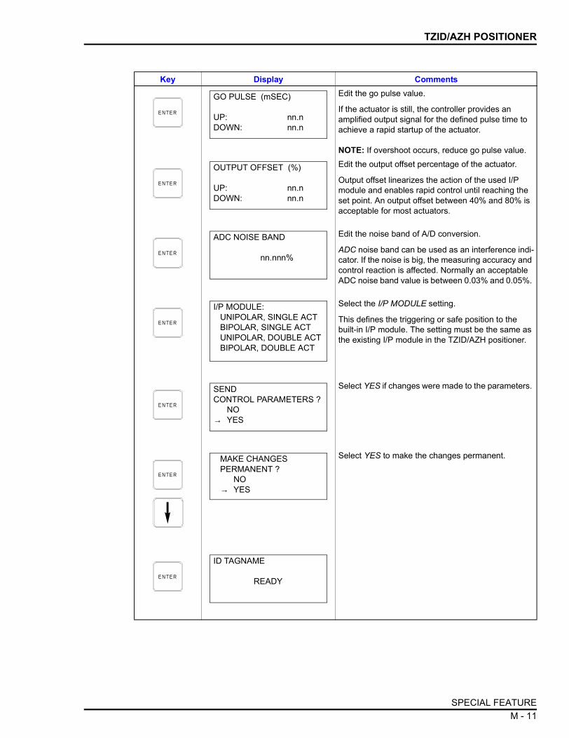
TZID/AZH POSITIONER
Edit the go pulse value.
If the actuator is still, the controller provides an amplified output signal for the defined pulse time to achieve a rapid startup of the actuator.
NOTE: If overshoot occurs, reduce go pulse value.Edit the output offset percentage of the actuator.
Output offset linearizes the action of the used I/P module and enables rapid control until reaching the set point. An output offset between 40% and 80% is acceptable for most actuators.
Edit the noise band of A/D conversion.
ADC noise band can be used as an interference indi-cator. If the noise is big, the measuring accuracy and control reaction is affected. Normally an acceptable ADC noise band value is between 0.03% and 0.05%.
Select the I/P MODULE setting.
This defines the triggering or safe position to the built-in I/P module. The setting must be the same as the existing I/P module in the TZID/AZH positioner.
Select YES if changes were made to the parameters.
Select YES to make the changes permanent.
Key Display Comments
E N TE R
GO PULSE (mSEC)
UP: nn.nDOWN: nn.n
E N TE R
OUTPUT OFFSET (%)
UP: nn.nDOWN: nn.n
E N TE R
ADC NOISE BAND
nn.nnn%
E N TE R
I/P MODULE:UNIPOLAR, SINGLE ACTBIPOLAR, SINGLE ACTUNIPOLAR, DOUBLE ACTBIPOLAR, DOUBLE ACT
E N TE R
SEND CONTROL PARAMETERS ?
NO→ YES
E N TE R
MAKE CHANGES PERMANENT ?
NO→ YES
E N TE R
ID TAGNAME
READY
SPECIAL FEATURE M - 11

TZID/AZH POSITIONER
Characteristic Curve
Use this function to create a user-defined characteristic curve by set-ting input and output points.
Key Display CommentsSelect CHARACTERIST. CURVE.
MODIFY and ERASE selections appear if a charac-teristic curve is already defined in the device. The characteristic curve is defined by 22 reference points.
Point 1 and point 22 are fixed at 0 and 100% respectively.
Enter an input point and press . Enter an out-put point.
Specify input and output values for points 2 through 21.
Each set of reference points must be greater than the previous set of points.
Select YES to send the values to the positioner.
S PE C IA LFE ATU R E
DEVICE INFORMATIONCONTROL PARAMETERS
→CHARACTERIST. CURVEOPERATING MODE
E N TE R
CHARACTERIST. CURVENEW
→ MODIFYERASE
E N TE R
POINT 1 INP (%)nn.nn
POINT 1 OUT (%)nn.nn
E N TE R
POINT 2 INP (%)nn.nn
POINT 2 OUT (%)nn.nn
ENTER
E N TE R
POINT 21 INP (%)nn.nn
POINT 21 OUT (%)nn.nn
E N TE R
SEND CURVE VALUES? NO
→ YES
SPECIAL FEATUREM - 12

TZID/AZH POSITIONER
Operating Mode
Use this function to change operating modes. The screen flow of thissection applies for TZID/AZH positioners with revision 5.x or greater.
Select YES to save changes. Key Display Comments
E N TE R
MAKE CHANGES PERMANENT?
NO→ YES
E N TE R
ID TAGNAME
READY
Key Display CommentsSelect OPERATING MODE.
Use this screen to select the operating mode.
Select AUTO for automatic adaptation of the control parameters.Select FIXED for fixed control parameters. Select MANUAL for manual actuation of control ele-ment.Select LOCAL to switch over the device from an externally selected operating mode to the internally selected mode.Select YES to change modes.
S PE C IA LFE ATU R E
DEVICE INFORMATIONCONTROL PARAMETERSCHARACTERIST. CURVE
→OPERATING MODE
E N TE R
→ CONTOLLING, AUTOCONTROLLING, FIXEDMANUALLOCAL
E N TE R
MAKE CHANGES PERMANENT?
NO→ YES
SPECIAL FEATURE M - 13

TZID/AZH POSITIONER
Device Self Test
Use this function to perform a self-test and report status of the posi-tioner.
Key Display Comments
E N TE R
ID TAGNAME
READY
Key Display CommentsSelect DEVICE SELF TEST.
If errors exist the message will display.
S PE C IA LFE ATU R E
CONTROL PARAMETERSCHARACTERIST. CURVE
OPERATING MODE→DEVICE SELF TEST
E N TE R
ID TAGNAME
READY
SPECIAL FEATUREM - 14

TZID/AZH POSITIONER
Master Reset
Use this function to return the positioner to factory settings.
Key Display CommentsSelect MASTER RESET.
This resets the positioner.
Select YES to reset the positioner.
S PE C IA LFE ATU R E
CHARACTERIST. CURVE
OPERATING MODEDEVICE SELF TEST
E N TE R
MAKE CHANGES PERMANENT?
NO→ YES
E N TE R
ID TAGNAME
READY
SPECIAL FEATURE M - 15

TZID/AZH POSITIONER
ERROR MESSAGES (TZID/AZH)
Table M-1 lists the TZID/AZH positioner error messages in alphabeti-cal order.
Table M-1. Error Messages for TZID/AZH Positioner
Message Description Corrective ActionACCESS DENIED, AUTO- STROKE IN PROGRESS
Attempted to change device parame-ters when autostroke was in process.
Wait for autostroke to complete and then try the operation again.
ALARM LIM SW1 REACH Valve position below low alarm limit. This is a warning message indicating a critical valve position.ALARM LIM SW2 REACH Alarm limit of SW2 has been reached.
AUTOSTROKE IS ALREADY STARTED
Attempted to start the autostroke cali-bration while it was already in progress.
Allow calibration process to finish.
AUTOSTROKE ERROR nn
At the end of autostroke, lists the autostroke error number if any occurred.
Find error number meanings in TZID/AZH instruction manual.
CONTROL NOT ACTIVE Valve position does not follow set point.
NOTE: An exclamation point (!) follow-ing the message indicates that the alarm output is active.
Activate automatic control in operat-ing mode 1.0 or 1.1 to terminate the inactive state.
DEVICE ERROR Internal data error. Reset positioner. If problem persists, load standard configuration.
DEADBAND TOO SMALL Deadband percentage value too small. Increase deadband percentage value.DEADBAND TOO LARGE Deadband percentage too large. Decrease deadband percentage
value.DIST METR LIMT EXCD Limit of distance meter exceeded. Start valve and positioner diagnosis
steps according to maintenance practices.
LEAK TOWARD ACTUATR Leakage towards actuator detected. Check tubing of actuator for leaks.POS OUT OF LEVR RNG Position out of lever range. Check if the positioner is mounted
properly.POSITIONING TIMEOUT Valve position does not follow set point.
Alarm output active.Check air supply pressure and tubing; check actuator, valve and positioner. Increase time limit using STT when hardware is ok.
ROM DEFECTIVE Positioner ROM is defective. Call ABB technical support.SET-PT OUT OF RANGE Set point is out of range. Adjust the set point range using the
STT.SHUT-OFF VALUE TOO LARGE
Shut-off value is too large. Reduce shut-off value.
SHUT-OFF VALUE TOO SMALL
Shut-off value is too small. Increase shut-off value.
SP NOT RCHD IN TIME Set point not reached within the dead-band time limit.
Check air supply pressure and tubing; check actuator, valve and positioner. Increase time limit using STT when hardware is ok.
Valve position does not follow set point.
ERROR MESSAGES (TZID/AZH)M - 16
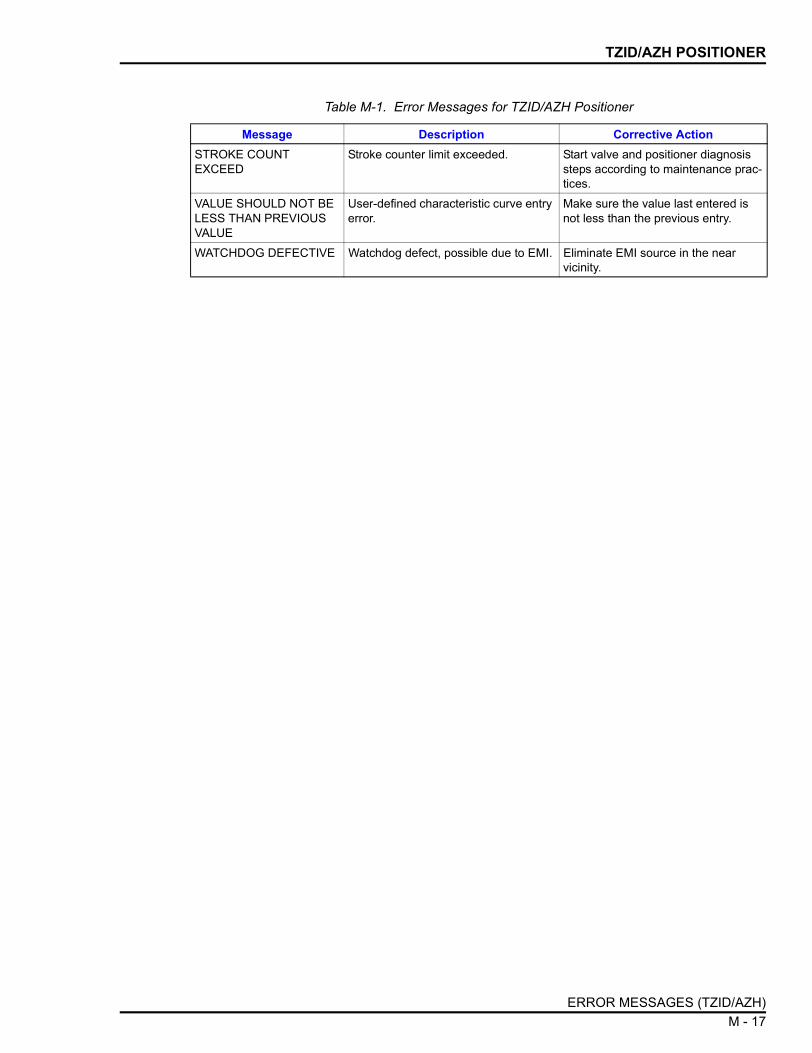
TZID/AZH POSITIONER
STROKE COUNT EXCEED
Stroke counter limit exceeded. Start valve and positioner diagnosis steps according to maintenance prac-tices.
VALUE SHOULD NOT BE LESS THAN PREVIOUS VALUE
User-defined characteristic curve entry error.
Make sure the value last entered is not less than the previous entry.
WATCHDOG DEFECTIVE Watchdog defect, possible due to EMI. Eliminate EMI source in the near vicinity.
Table M-1. Error Messages for TZID/AZH Positioner
Message Description Corrective Action
ERROR MESSAGES (TZID/AZH) M - 17

APPENDIX N - TB82 TRANSMITTER
INTRODUCTION
This appendix covers the configuration, calibration and special fea-ture functions of the TB82 transmitter. Table N-1 lists problem codesand Table N-2 lists error codes of the TB82 transmitter.
Refer to OPERATING PROCEDURES in Section 4 for information onthe following functions:
CREATE/MODIFY CONFIGURATION
A configuration can be created offline, without a connected fielddevice. Refer to Figure N-1 for an overview of the configurationfunction. The following table details the configuration process.
This procedure covers pH transmitters. Any differences betweenother TBI devices will be noted in the Comments column.
• Send configurations. • Select configurations.• Get configurations. • Erase configurations.• View configurations. • Operational functions.
Figure N-1. Configuration Flowchart (TB82)
T02394A
ID TAG
E N TE RM E S S AG E
TR A N S M ITTERTY P E
EN TE RDATE
EN TE RTE M P E R ATU R E
(p H O N LY)
S E LE C TM O D E
DA M P IN G
D E V IC ETYP E
E N TE RD E S C R IP TO R
TEM PE R ATU R EC O M PE N S ATIO NTY P E (p H O N LY )
E N TE R LOW E RAN D U P P E R
R A N G E VA LU E
C O N FIG U R ATIO NN A M E
S E LE C TO U TP U T
TY PE
S AV EC O N FIG U R ATIO N
CONFI
GURE
INTRODUCTION N - 1

TB82 TRANSMITTER
Key Display CommentsSelect NEW to create a configuration. To modify an existing configuration, select MODIFY. The screen sequence is the same, however, the MODIFY screens will appear with the values and arrow posi-tions as they were originally configured.
Select HART.
Select a TBI device. The configuration shown here is generalized for all TBI devices. Differences that occur are noted.
Enter a name for the configuration ID tag using up to 8 ASCII characters. To select a character, press the key that has the desired character. Continue to press the key until the desired character appears. Use the right arrow key to move to the next character. Use the left arrow key to go back to the previous charac-ter.Select ANALOG.
NOTE: The DIGITAL selection should only be made when using the device in multidrop mode. A CHAN-NEL # prompt appears when DIGITAL is selected.
Type a descriptive message using up to 32 charac-ters. Use this field to note important information about the device or installation.
Type a descriptor string using up to 16 characters. This field can be used for notations about the device or process.
To select a character, press the key that has the desired character. Continue to press the key until the desired character appears. Use the right arrow key to move to the next character. Use the left arrow key to go back to the previous character.
C O N F IG
CONFIGURATION→ NEW
MODIFYERASE
E N TE R
DEVICE TYPE
ABB FSK→ HART
E N TE R
TRANSMITTER TYPEPTH EBTH
→ TB82 pH TB82 ORPTB82 pION TB82 CONC
E N TE R
STT04 CONFIGURATION[ ]
←PREVIOUS NEXT→
E N TE R
SELECT MODE: → ANALOG
DIGITAL
E N TE R
MESSAGE :
←PREVIOUS NEXT→
E N TE R
DESCRIPTOR:
←PREVIOUS NEXT→
CREATE/MODIFY CONFIGURATIONN - 2

TB82 TRANSMITTER
Enter a day and press . Enter a month and press . Enter a year.
This date can represent the creation date of the con-figuration, the date the device or element was installed, or some other significant date.
Select Linear.
The OUTPUT TYPE screen does not appear when the transmitter type is TB82 CONC.
NOTE: Remote communications do not support the function generator feature for the TB82. Function generator output points must be specified locally at the device.Enter a value between 0 and 100. Damping is used to smooth out a noisy signal. Use a low value for a clean signal and a higher number for noisy signals. Default setting is 0.5 seconds.
The DAMPING screen does not appear when the transmitter type is TB82 CONC.Input lower range value (4 mA) using the arrow keys, then press . Input the upper range value (20 mA).
The range values screen does not appear when the transmitter type is TB82 CONC.
Select a temperature compensation type.
This screen appears for TB82 pH.
NOTE: AUTO SOL. (ADV) is only available for TB82 transmitters operating in advance mode.
Enter a temperature.
This screen appears for TB82 pH and only if MAN-UAL is the temperature compensation type.
Select YES.
Key Display Comments
E N TE R
DATE:DAY: nnMONTH: nnYEAR: nnnn
ENTERENTER
E N TE R
OUTPUT TYPE:→ LINEAR
FUNC GENERATOR
E N TE R
DAMPING: (0 - 100 sec)
E N TE R
LOWER RANGE VALnn.nn UNITS
UPPER RANGE VALnn.nn UNITS
ENTER
E N TE R
TEMP COMP TYPE→ MANUAL
AUTOMATICAUTO SOL. (ADV)
E N TE R
ENTERTEMPERATURE:
nn.nn UNITS
E N TE R
STORE THIS CONFIGURATION?
NO→ YES
CREATE/MODIFY CONFIGURATION N - 3

TB82 TRANSMITTER
CALIBRATION
This section details the TB82 transmitter calibration functions usingan STT04 terminal.
NOTE: When calibrating, a field device must be connected to theSTT04 terminal.
Refer to Figure N-2 for an overview of the calibration functions.
One-point Calibration
This procedure describes how to perform a one-point calibration. Thisprocedure is generalized for all TB82 devices (pH, ORP, pION andCONC). Differences between devices are noted in the Commentscolumn of the table.
Key Display Comments
E N TE R
ID TAGNAME
READY
Figure N-2. Calibration Flowchart (TB82)
T 02428 A
C A LIB R ATIO NC O M P LE TE
V IE WC A LIB R ATIO N
W A R N IN G S(IF A N Y )
V IE WC A LC U LAT E D
O FFS E T
R ELE A S EO U TP U T H O LD(2 P O IN T O N LY )
O U TP U TC A LIB R ATIO N
E D ITC A LIB R ATIO N
TE M P E R ATU R EC A LIB R ATIO N
R E S E TC A LIB R ATIO N
C A LIB R AT IO NM E TH O D
pHC A LIB R ATIO N
E N T ERP R O C E S S
S LO P E
E N T ERTE M P E R ATU R E
A R R OW K E Y S
M E T ER VA LU E E N TRY
A D JU S TO U TP U TTO 4 m A
1 P O IN TC A LIB R ATIO N
E N TE RP RO C E S S
O FF S E T
A D JU S TO U TP U TTO 20 m A
V IEWP E R C E N TAG E
pH VA LU E
E N TE RTE M P E R ATU R E
O FFS E T
V IE WC A LC U LAT E DE FF IC IE N C Y
A P P LYLOW A N D H IG H
VA LU E
E N TE RTE M P E R ATU R E
S LO P E
E N T E RN EW VA LU E
E N T E RLOW A N D H IG H
pH VALU E
4 m AC A LIB R ATIO N
E N T ER M E T E RVA LU E 4.000
2 P O IN TC A LIB R ATIO N
20 m AC A LIB R ATIO N
E N TE R M E T ERVA LU E 20.000
E N TE RP R O C E S S
TE M P E R ATU R E
CALIBRATE
CALIBRATIONN - 4

TB82 TRANSMITTER
One-point calibration conducts an offset adjustment on the sensorinput. Use this type of calibration when the sensor is in the finalinstalled location.
Key Display Comments
This operation will cause a change in output not cor-responding to the input. Be sure the control loop is in manual.
Select YES.
Select a calibration type.
Throughout this procedure the variable nnnn repre-sents one of the following device types:
pH ORP PION CONC
Select 1 POINT CAL. Use this calibration method when the sensor is in its final location.
Displays the current input value.
Enter the desired value.
The terminal displays the calculated efficiency in per-centage.
C A LI- B R ATE
OUTPUT WILL BEAFFECTED! PROCEED?
NO→ YES
E N TE R
→ nnnn CALTEMP. CALEDIT CALRESET CAL
E N TE R
nnnn CAL→ 1 POINT CAL
2 POINT CAL
E N TE R
nn.nn UNITS
PRESS ENTERWHEN STABLE
E N TE R
ENTER NEW VALUE
_ nn.nn UNITS
E N TE R
CALCULATED EFFICIENCY
nn.n %PRESS ENTER
CALIBRATION N - 5

TB82 TRANSMITTER
Two-point Calibration
Two-point calibration conducts an offset and slope adjustment on asensor to determine response characteristics before final locationinstallation.
The terminal displays the calculated sensor offset in millivolts.
If any warnings or messages exist pertaining to this device, the terminal will list them.
Key Display Comments
E N TE R
CALCULATED SENSOR OFFSET
nnn.n mVPRESS ENTER
E N TE R
ID TAGNAME
READY
Key Display Comments
This operation will cause a change in output not cor-responding to the input. Selecting YES will hold the output during calibration.
Select YES.
Select a calibration type.
Throughout this procedure the variable nnnn repre-sents one of the following device types:
pH ORP PION CONC
Select 2 POINT CAL.
C A LI- B R ATE
OUTPUT WILL BEAFFECTED! PROCEED?
NO→ YES
E N TE R
→ nnnn CALTEMP. CALEDIT CALRESET CAL
E N TE R
nnnn CAL1 POINT CAL
→ 2 POINT CAL
CALIBRATIONN - 6

TB82 TRANSMITTER
Enter a process temperature value.
This screen appears only for 2 POINT CAL when performing a pH CAL. 25°C is the default value.
Enter the low value of the buffer or standard and press . Enter the high value.
The low default value is 4.0 pH. The high default value is 7.0 pH.
Apply the low value of the buffer or standard.
Apply the high value of the buffer or standard.
The terminal displays the calculated efficiency in per-centage.
The terminal displays the calculated sensor offset in millivolts.
Select YES to release output hold. Screen appears at the end of two-point calibration when device is in the analog mode.
If any warnings or messages exist pertaining to this device, the terminal will list them.
Key Display Comments
E N TE R
ENTER PROCESSTEMPERATURE
nn.nn O C
E N TE R
LOW CALIBnn UNITS
HIGH CALIBnn UNITS
ENTER
E N TE R
APPLY n.nn UNITS
PRESS ENTERWHEN STABLE
E N TE R
APPLY n.nn UNITS
PRESS ENTERWHEN STABLE
E N TE R
CALCULATED EFFICIENCY
nn.n %PRESS ENTER
E N TE R
CALCULATED SENSOR OFFSET
nnn.n mVPRESS ENTER
E N TE R
RELEASE OUTPUT HOLDNO
→ YES
E N TE R
ID TAGNAME
READY
CALIBRATION N - 7

TB82 TRANSMITTER
Temperature Calibration
This procedure describes how to perform a temperature calibration.
Key Display Comments
This operation will cause a change in output not cor-responding to the input. Selecting YES will hold the output during calibration.
Select YES.
Select TEMP. CAL.
Enter the temperature. Default temperature is 25°C.
C A LI- B R ATE
OUTPUT WILL BEAFFECTED! PROCEED?
NO→ YES
E N TE R
nnnn CAL→ TEMP. CAL
EDIT CALRESET CAL
E N TE R
ENTER TEMPERATURE:
nn.nn O C
E N TE R
ID TAGNAME
READY
CALIBRATIONN - 8

TB82 TRANSMITTER
Edit Calibration
This procedure describes how to edit a calibration.
Key Display Comments
This operation will cause a change in output not cor-responding to the input. Selecting YES will hold the output during calibration.
Select YES.
Select EDIT CAL.
Enter the sensor slope value and press . Valid values are 40% to 150%.
Enter a sensor offset value. Valid values are -1,000 to +1,000 mV.
Enter a temperature slope value and press . Valid range is 0.2 to 1.5.
Enter a temperature offset value. Valid range is -40° to 40°C.
If any warnings or messages exist pertaining to this device, the terminal will list them.
C A LI- B R ATE
OUTPUT WILL BEAFFECTED! PROCEED?
NO→ YES
E N TE R
nnnn CALTEMP. CAL
→ EDIT CALRESET CAL
E N TE R
PROCESS
SLOPE : nnn.nnnnOFFSET: nnnn.nnnn
ENTER
E N TE R
TEMPERATURE
SLOPE : nn.nnnnOFFSET: nnn.nnnn
ENTER
E N TE R
ID TAGNAME
READY
CALIBRATION N - 9

TB82 TRANSMITTER
Reset Calibration
This procedure describes how to reset a calibration back to thedefault settings.
Key Display Comments
This operation will cause a change in output not cor-responding to the input. Selecting YES will hold the output during calibration.
Select YES.
Select RESET CAL.
This function sets all process sensor and tempera-ture sensor calibration data to the default settings. The following are the factor settings.
Sensor slope: 100 %Sensor offset: 0 mVTemperature slope: 1Temperature offset: 0°C
Select YES to reset the calibration.
C A LI- B R ATE
OUTPUT WILL BEAFFECTED! PROCEED?
NO→ YES
E N TE R
nnnn CALTEMP. CALEDIT CAL
→ RESET CAL
E N TE R
OUTPUT WILL BEAFFECTED! PROCEED?
NO→ YES
E N TE R
ID TAGNAME
READY
CALIBRATIONN - 10

TB82 TRANSMITTER
Output D/A Calibration
Output D/A Calibration is used to trim the output signal to maintainprecise transmission of the process variable. The procedure that fol-lows details output adjustment using the arrow keys. Adjustment canbe made by meter value entry. Refer to Appendix B for details pertain-ing to meter value entry adjustment.
Key Display Comments
This operation will cause a change in output not cor-responding to the input. Selecting YES will hold the output during calibration.
Select YES.
Select OUTPUT D/A CAL.
Select UPDOWN ARROW KEYS. Use the arrow keys to adjust the output to a value other than 4 or 20 mA.
Use the METER VALUE ENTRY to adjust the output to 4 and 20 mA. Refer to Appendix B for details about meter value entry.
Use the arrow keys to adjust output to 4 mA.
NOTE: When increasing or decreasing the mA sig-nal, the increments of change increase with succes-sive depressions until the maximum level of change is reached. By changing direction you will return to the smallest increment of change. This adjustment technique speeds up the adjustment process without affecting fine adjustment.
C A LI- B R ATE
OUTPUT WILL BEAFFECTED! PROCEED?
NO→ YES
E N TE R
nnnn CALEDIT CALRESET CAL
→ OUTPUT D/A CAL
E N TE R
D/A CAL USING→ UPDOWN ARROW KEYS
METER VALUE ENTRY
E N TE R
ADJUST TO 4 mA
THEN HIT ENTER
CALIBRATION N - 11

TB82 TRANSMITTER
SPECIAL FEATURE
The following section details unique special feature functions for theTB82.
Sensor Data
This procedure describes how to view sensor data.
Use the arrow keys to adjust output shown on the meter to 20 mA.
Key Display Comments
E N TE R
ADJUST TO 20 mA
THEN HIT ENTER
E N TE R
ID TAGNAME
READY
Key Display Comments
Select SENSOR DATA.
View slope and offset of the process.
Valid slope values are 40% to 150%. Valid offset val-ues are -1,000 to +1,000 mV.
View slope and offset of the temperature.
Valid range for slope is 0.2 to 1.5. Valid range for off-set is -40° to 40°C.
S PE C IA LFE ATU R E
FIX/CANCEL OUTPUT→ SENSOR DATA
HART SP. FEATURE
E N TE R
PROCESS
SLOPE : nn.nnnnOFFSET: nn.nnnn
E N TE R
TEMPERATURE
SLOPE : nn.nnnnOFFSET: nn.nnnn
E N TE R
ID TAGNAME
READY
SPECIAL FEATUREN - 12

TB82 TRANSMITTER
HART Special Feature
This section describes the HART special features under the specialfeature key relating to the TB82.
Sensor Setup
Use this special feature function to view the upper and lower limitsand the minimum span, serial number, and final assembly number ofthe sensor.
Key Display Comments
Select HART SP. FEATURE.
Refer to FIX OUTPUT/CANCEL FIX OUTPUT in Section 4 for details about fix and cancel fix output.
Select SENSOR SETUP.
View the sensor upper and lower limits.
View the sensor minimum span.
View the sensor serial number.
S PE C IA LFE ATU R E
FIX/CANCEL OUTPUTSENSOR DATA
→ HART SP. FEATURE
E N TE R
→ SENSOR SETUPMASTER RESET# RESP PREAMBLESRST CFG CHANGED
E N TE R
SENSOR UPPER LIMITnnnn UNITS
SENSOR LOW LIMITnnnn UNITS
E N TE R
MINIMUM SPANn.nn UNITS
E N TE R
SENSOR SERIAL #
nnnnnnnn
SPECIAL FEATURE N - 13

TB82 TRANSMITTER
Master Reset
Use this function to perform a transmitter reset.
View the final assembly number.
If any warnings or messages exist pertaining to this device, the terminal will list the message.
Key Display Comments
E N TE R
FINAL ASSEMBLY #
nnnnnnnn
E N TE R
ID TAGNAME
READY
Key Display Comments
Select HART SP. FEATURE.
Select MASTER RESET.
This function performs a soft reset of the TB82.
Select YES to perform a master reset.
S PE C IA LFE ATU R E
FIX/CANCEL OUTPUTSENSOR DATA
→ HART SP. FEATURE
E N TE R
SENSOR SETUP→ MASTER RESET
# RESP PREAMBLESRST CFG CHANGED
E N TE R
OUTPUT WILL BEAFFECTED! PROCEED?
NO→ YES
SPECIAL FEATUREN - 14

TB82 TRANSMITTER
Number of Response Preambles
Use this function to set the number of response preambles to be sentfrom the device at the start of the response.
If any warnings or messages exist pertaining to this device, the terminal will list the message.
Key Display Comments
E N TE R
ID TAGNAME
READY
Key Display Comments
Select HART SP. FEATURE.
Select # RESP PREAMBLES.
Enter a number between 5 and 20. The communica-tion device requires a certain value.
The default value is 5 response preambles.
S PE C IA LFE ATU R E
FIX/CANCEL OUTPUTSENSOR DATA
→ HART SP. FEATURE
E N TE R
SENSOR DATAMASTER RESET
→ # RESP PREAMBLESRST CFG CHANGED
E N TE R
# RESP. PREAMBLES
n
E N TE R
ID TAGNAME
READY
SPECIAL FEATURE N - 15

TB82 TRANSMITTER
Reset Configuration Change Flag
Use this function to reset the change flag. If a change is made to aconfiguration a change flag is set, indicating a change to the originalconfiguration. This function removes the change flag.
PROBLEM AND ERROR CODES (TB82)
Table N-1 lists the TB82 transmitter problem codes that can appearon the STT04 terminal. Problem codes result from fault conditionsthat affect the performance of the device.
Table N-2 lists the TB82 transmitter error codes that can appear onthe STT04 terminal. Error codes result from fault conditions that ren-der the device inoperable. All codes are listed in alphabetical order.
Key Display Comments
Select HART SP. FEATURE.
Select RST CFG CHANGED FLG to reset the change flag.
S PE C IA LFE ATU R E
FIX/CANCEL OUTPUTSENSOR DATA
→ HART SP. FEATURES
E N TE R
SENSOR DATAMASTER RESET# RESP PREAMBLES
→ RST CFG CHANGED FLG
E N TE R
ID TAGNAME
READY
PROBLEM AND ERROR CODES (TB82)N - 16

TB82 TRANSMITTER
Table N-1. Problem Codes of TB82 Transmitter
Code Description Corrective ActionBA.CHKS Incorrect or missing 3-kΩ
Balco temperature sensor checksum
Cycle transmitter power.Remove transmitter from installed location and relocate to noise-free environment. If problem does not appear, transmitter needs new final location or additional shielding on transmitter and/or wiring.Contact ABB.
BA.F.CAL Out of range or missing factory calibration for 3-kΩ Balco temperature sensor
Contact ABB for factory calibration procedure. Calibrate temper-ature sensor for short-term usage until factory calibration can be performed.
BAD.SEE Bad SEEPROM or pH/ORP/pION input PCB assembly
Input PCB assembly factory calibration constants can not be loaded. Calibrate sensor and order replacement pH/ORP/pION input PCB assembly. Existing assembly should properly function until new assembly is received.
BLNK.UP Blank microprocessor EEPROM
Cycle transmitter power.Contact ABB.
GND LP Ground loop present or shorted sensor cable
Verify sensor wiring connections.Verify sensor does not have any exposed wire from nicks, etc. If it does, repair (if possible) or replace.Remove any liquids, oils, scales or corrosion from transmitter ter-minal block or extension cable junction box terminals.Verify sensor responds to pH buffers. Replace sensor and/or sensor extension cable (if present) if sensor does not respond.Electronically test sensor (refer to the product instruction). Replace if it does not meet requirements.
HI.C.CKT Cable diagnostic circuit failure - high range error
Verify sensor wiring connections. Remove any liquids, oils, scales or corrosion from transmitter ter-minal block or extension cable junction box terminals.Electronically test sensor. Replace if it does not meet requirements.Input PCB assembly diagnostic circuit failure exists. Disable diagnostics and order replacement input PCB assembly. Existing input PCB assembly should properly function until new assembly is received.
HI.CA.AD Cable diagnostic signal above transmitter A/D range
Input PCB assembly diagnostic circuit failure exists. Disable diagnostics and order replacement input PCB assembly. Existing input PCB assembly should properly function until new assembly is received.
HI.EFF High sensor efficiency (>110%)
Verify proper buffer values were used for calibration and repeat buffer calibration.Clean sensor and repeat buffer calibration.
PROBLEM AND ERROR CODES (TB82) N - 17

TB82 TRANSMITTER
HI.G.CKT pH measuring electrode impedance circuit failure - high range error
Verify sensor wiring connections. Verify sensor does not have any exposed wire from nicks, etc. If it does, repair (if possible) or replace.Remove any liquids, oils, scales or corrosion from transmitter ter-minal block or extension cable junction box terminals.Verify sensor responds to pH buffers. Replace sensor and/or sensor extension cable (if present) if sensor does not respond.Electronically test sensor. Replace if it does not meet require-ments.Input PCB assembly glass pH impedance circuit failure exists. Disable diagnostics and order replacement input PCB assembly. Existing input PCB assembly should properly function until new assembly is received.
HI.GL.DA pH measuring electrode impedance above transmitter A/D range
Input PCB assembly glass pH impedance circuit failure exists. Disable diagnostics and order replacement input PCB assembly. Existing input PCB assembly should properly function until new assembly is received.
HI.LOOP Current loop above upper range value (+0.4 mA hysteresis)
Verify process conditions are within configured output range. If PV is outside configured range, increase output range.Verify sensor wiring connections. Remove any liquids, oils, scales or corrosion from transmitter ter-minal block or extension cable junction box terminals.Clean sensor and perform a buffer and process calibration.Conduct a temperature calibration. If not using temperature sen-sor, verify configuration for TMP.SNS is NONE.Electronically test the sensor and temperature compensator (refer to the product instruction). Replace sensor if it does not meet requirements.
+HI.OFF Large positive sensor offset(>180 mV)
Clean sensor and perform buffer and process calibration.Inspect sensor and cabling for shorts. Remove all potential shorts to ground, conduit or metals.If sensor is functioning properly, order spare sensor to replace existing sensor. Replace existing sensor with spare when trans-mitter does not accept calibration values.
-HI.OFF Large negative sensor offset (<-180 mV)
Clean sensor and perform buffer and process calibration.Inspect sensor and cabling for shorts. Remove all potential shorts to ground, conduit or metals.If sensor is functioning properly, order spare sensor to replace existing sensor. Replace existing sensor with spare when trans-mitter does not accept calibration values.
Table N-1. Problem Codes of TB82 Transmitter (continued)
Code Description Corrective Action
PROBLEM AND ERROR CODES (TB82)N - 18

TB82 TRANSMITTER
HI.PV PV above transmitter range Verify process conditions are within transmitter range. PV must be within transmitter range.Verify sensor wiring connections. Verify sensor does not have any exposed wire from nicks, etc. If it does, repair (if possible) or replace.Remove any liquids, oils, scales or corrosion from transmitter ter-minal block or extension cable junction box terminals.Verify sensor responds to pH buffers. Replace sensor and/or sensor extension cable (if present) if sensor does not respond.Electronically test sensor (refer to the product instruction). Replace if it does not meet requirements.
HI.R.CKT Reference impedance circuit failure - high range error
Verify sensor wiring connections. Verify reference is clean. Remove any foreign material.Clean sensor and verify it responds to pH buffer. Replace sensor if it does not respond. Change configuration to increase reference impedance limit if sensor is functioning properly in buffers and is in final installed location.Input PCB reference impedance circuit failure exists. Disable diagnostics and order replacement input PCB assembly. Existing input PCB assembly should properly function until new assembly is received.
HI.REF.Z High reference electrode impedance
Verify sensor wiring connections.Verify reference is clean. Remove any foreign material. Clean sensor and verify it responds to pH buffer. Replace sensor if it does not respond. Change configuration to increase reference impedance limit if sensor is functioning properly in buffers and is in final installed location.
HI.RZ.AD Reference impedance above transmitter A/D range
Input PCB reference impedance circuit failure exists. Disable diagnostics and order replacement input PCB assembly. Existing input PCB assembly should properly function until new assembly is received.
HI.T.AD Open or missing temperature sensor
Verify process conditions are within transmitter range. PV must be within transmitter range.Verify process conditions are within configured output range. If PV is outside configured range, increase output range.Verify sensor wiring connections. Remove any liquids, oils, scales or corrosion from transmitter ter-minal block or extension cable junction box terminals.Clean sensor and perform a buffer and process calibration.Conduct temperature calibration. If not using temperature sen-sor, verify configuration for TMP.SNS is NONE.Electronically test sensor and temperature compensator (refer to the product instruction). Replace sensor if it does not meet requirements.Replace pH/ORP/pION input PCB assembly.
Table N-1. Problem Codes of TB82 Transmitter (continued)
Code Description Corrective Action
PROBLEM AND ERROR CODES (TB82) N - 19

TB82 TRANSMITTER
HI.TEMP Temperature above transmitter range
Verify process conditions are within transmitter range. PV must be within transmitter range.Verify process conditions are within configured output range. If PV is outside configured range, increase output range.Verify sensor wiring connections. Remove any liquids, oils, scales or corrosion from transmitter ter-minal block or extension cable junction box terminals.Clean sensor and perform a buffer and process calibration.Conduct a temperature calibration. If not using temperature sen-sor, verify configuration for TMP.SNS is NONE.Electronically test the sensor and temperature compensator (refer to the product instruction). Replace sensor if it does not meet requirements.
LO.C.CKT Cable diagnostic circuit failure - low range error
Verify sensor wiring connections. Remove any liquids, oils, scales or corrosion from transmitter ter-minal block or extension cable junction box terminals.Electronically test sensor. Replace if it does not meet require-ments.Input PCB assembly diagnostic circuit failure exists. Disable diagnostics and order replacement input PCB assembly. Existing input PCB assembly should properly function until new assembly is received.
LO.CA.AD Cable diagnostic signal below transmitter A/D range
Input PCB assembly diagnostic circuit failure exists. Disable diagnostics and order replacement input PCB assembly. Existing input PCB assembly should properly function until new assembly is received.
LO.EFF Low sensor efficiency (<60%)
Verify proper buffer values were used for calibration and repeat buffer calibration.Clean sensor and repeat buffer calibration.Look for shorts in sensor and extension cable. Remove all poten-tial shorts. Remove any liquids, oils, scales or corrosion from transmitter terminal block or junction box terminals.If sensor is functioning properly, order new sensor to replace existing sensor once transmitter does not accept calibration val-ues.
LO.G.CKT pH measuring electrode impedance circuit failure - low range error
Verify sensor wiring connections. Verify glass electrode is intact. If broken, replace sensor.Remove any liquids, oils, scales or corrosion from transmitter ter-minal block or extension cable junction box terminals.Verify sensor responds to pH buffers. Replace sensor if it does not respond.Change configuration to proper analyzer type if sensor is not a glass pH sensor.Input PCB assembly glass pH impedance circuit failure exists. Disable diagnostics and order replacement input PCB assembly. Existing input PCB assembly should properly function until new assembly is received.
Table N-1. Problem Codes of TB82 Transmitter (continued)
Code Description Corrective Action
PROBLEM AND ERROR CODES (TB82)N - 20

TB82 TRANSMITTER
LO.GL.AD pH measuring electrode impedance below transmitter A/D range
Input PCB assembly glass pH impedance circuit failure exists. Disable diagnostics and order replacement input PCB assembly. Existing input PCB assembly should properly function until new assembly is received.
LO.GLS.Z Low pH measuring electrode impedance
Verify sensor wiring connections.Verify glass electrode is intact. If broken, replace sensor.Remove any liquids, oils, scales or corrosion from transmitter ter-minal block or extension cable junction box terminals.Verify sensor responds to pH buffers. Replace sensor if it does not respond.Change configuration to proper analyzer type if sensor is not a glass pH sensor.
LO.LOOP Current loop below lower range value (-0.2 mA hysteresis)
Verify process conditions are within configured output range. If PV is outside configured range, increase output range.Verify sensor wiring connections.Remove any liquids, oils, scales or corrosion from transmitter ter-minal block or extension cable junction box terminals.Clean sensor and perform a buffer and process calibration.Conduct a temperature calibration. If not using temperature sen-sor, verify configuration for TMP.SNS is NONE.Electronically test the sensor and temperature compensator (refer to the product instruction). Replace sensor if it does not meet requirements.
LO.PV PV below transmitter range Verify process conditions are within transmitter range. PV must be within transmitter range.Verify sensor wiring connections. Verify sensor does not have any exposed wire from nicks, etc. If it does, repair (if possible) or replace.Remove any liquids, oils, scales or corrosion from transmitter ter-minal block or extension cable junction box terminals.Verify sensor responds to pH buffers. Replace sensor and/or sensor extension cable (if present) if sensor does not respond.Electronically test sensor (refer to the product instruction). Replace if it does not meet requirements.
LO.R.CKT Reference impedance cir-cuit failure - low range error
Verify sensor wiring connections. Electronically test sensor. Replace if it does not meet require-ments.Input PCB reference impedance circuit failure exists. Disable diagnostics and order replacement input PCB assembly. Existing input PCB assembly should properly function until new assembly is received.
LO.RZ.AD Reference impedance below transmitter A/D range
Input PCB reference impedance circuit failure exists. Disable diagnostics and order replacement input PCB assembly. Existing input PCB assembly should properly function until new assembly is received.
Table N-1. Problem Codes of TB82 Transmitter (continued)
Code Description Corrective Action
PROBLEM AND ERROR CODES (TB82) N - 21

TB82 TRANSMITTER
LO.T.AD Shorted temperature sensor Verify process conditions are within transmitter range. PV must be within transmitter range.Verify process conditions are within configured output range. If PV is outside configured range, increase output range.Verify sensor wiring connections. Remove any liquids, oils, scales or corrosion from transmitter ter-minal block or extension cable junction box terminals.Clean sensor and perform buffer and process calibration.Conduct temperature calibration. If not using temperature sen-sor, verify configuration for TMP.SNS is NONE.Electronically test sensor and temperature compensator (refer to the product instruction). Replace sensor if it does not meet requirements.Replace pH/ORP/pION input PCB assembly.
LO.TEMP Temperature below transmitter range
Verify process conditions are within transmitter range. PV must be within transmitter range.Verify process conditions are within configured output range. If PV is outside configured range, increase output range.Verify sensor wiring connections. Remove any liquids, oils, scales or corrosion from transmitter ter-minal block or extension cable junction box terminals.Clean sensor and perform a buffer and process calibration.Conduct a temperature calibration. If not using temperature sen-sor, verify configuration for TMP.SNS is NONE.Electronically test sensor and temperature compensator (refer to the product instruction). Replace sensor if it does not meet requirements.
NO.F.CAL Missing factory calibration and functional SEEPROM
Contact ABB for factory calibration procedure. Calibrate sensor for short-term usage until factory calibration can be performed.
OPEN Open sensor cable or sensor out of solution
Verify sensor wiring connections.Verify sensor does not have any exposed wire from nicks, etc. If it does, repair (if possible) or replace.Remove any liquids, oils, scales or corrosion from transmitter ter-minal block or extension cable junction box terminals.Verify sensor responds to pH buffers. Replace sensor and/or sensor extension cable (if present) if sensor does not respond.Electronically test sensor (refer to the product instruction). Replace if it does not meet requirements.
PV.CHKS Incorrect or missing PV checksum
Cycle transmitter power.Remove transmitter from installed location and relocate to noise-free environment. If problem does not appear, transmitter needs new final location or additional shielding on transmitter and/or wiring.Contact ABB.
Table N-1. Problem Codes of TB82 Transmitter (continued)
Code Description Corrective Action
PROBLEM AND ERROR CODES (TB82)N - 22

TB82 TRANSMITTER
PT.CHKS Incorrect or missing Pt 100 temperature sensor checksum
Cycle transmitter power.Remove transmitter from installed location and relocate to noise-free environment. If problem does not appear, transmitter needs new final location or additional shielding on transmitter and/or wiring.Contact ABB.
PT.F.CAL Out of range or missing factory calibration for Pt 100 temperature sensor
Contact ABB for factory calibration procedure. Calibrate temper-ature sensor for short-term usage until factory calibration can be performed.
PZ.CHKS Incorrect or missing reference impedance measurement checksum
Cycle transmitter power.Remove transmitter from installed location and relocate to noise-free environment. If problem does not appear, transmitter needs new final location or additional shielding on transmitter and/or wiring.Contact ABB.
PV.F.CAL Out of range or missing factory calibration for PV
Contact ABB for factory calibration procedure. Calibrate sensor for short-term usage until factory calibration can be performed.
ROM.EMI Unverifiable EEPROM/ROM bus read operation
Cycle transmitter power.Contact ABB.
ROM.SUM Incorrect EPROM checksum
Cycle transmitter power.Contact ABB.
RZ.F.CAL Out of range or missing factory calibration for reference impedance measurement
Contact ABB for factory calibration procedure. Reference imped-ance diagnostic will not be operational until factory calibration is performed. Disable diagnostics until factory calibration can be performed.
SEE.EMI Unverifiable SEEPROM bus read operation
Cycle transmitter power.Contact ABB.
Table N-1. Problem Codes of TB82 Transmitter (continued)
Code Description Corrective Action
Table N-2. Error Codes of the TB82 Transmitter
Code DescriptionFC.PCB 4 wire conductivity board with pH/ORP/pION firmware.HI.PV.AD Overrange PV A/D.LO.PV.AD Underrange PV A/D.TC.PCB Toroidal conductivity board with PH/ORP/pION firmware.
PROBLEM AND ERROR CODES (TB82) N - 23

APPENDIX O - STT04 DOWNLINK SOFTWARE
INTRODUCTION
This appendix covers the functions of the STT04 DownLink software.The software is used in conjunction with the STT04 terminal. Down-Link software features include:
• PC to STT04 interface.• STT04 firmware upgrades via the internet.• Upload and download device configurations from PC.• Create configuration databases on PC.
The software is provided on a CD and is shipped with the STT04 ter-minal. Software installation is detailed in Section 3.
NOTE: If you do not have DownLink software, contact the nearestABB sales office for availability.
SECURITY
An assigned user name and password are required to access Down-Link software. The administrator can choose to bypass the passwordfeature of DownLink software. User names and passwords areassigned with the Password program. Access to the Password pro-gram requires the Password Key disk. Only personnel at the highestsecurity level should have access to the Password Key disk in orderto ensure security.
Starting the Password Program
After installing the software, the password program should be setup inorder to access the features of DownLink software.
1. Click Start and select Programs.
2. Highlight ABB and select Password.
Adding a User
Use this function to add a user to the STT04 DownLink software.
1. Start the Password program. Refer to Starting the PasswordProgram.
2. Insert the Password Key disk into a floppy disk drive.
3. Click Key and type the appropriate disk drive letter (i.e., A:) andclick Verify. The screen shown in Figure O-1 appears.
INTRODUCTION O - 1

STT04 DOWNLINK SOFTWARE
4. Click Password and select Add. The screen shown in Figure O-2appears.
5. Click in Enter your User Name and type a user name of at leastthree and up to 32 characters.
6. Click in Enter your Password and type a unique password of atleast three and up to 24 characters. The characters typed show asasterisks (*) for security reasons.
7. Click in Enter your Password Again and type the password again.
8. Select a security level by clicking the appropriate level. Refer toTable O-1 for level descriptions.
TC00654B
Figure O-1. Password Key Screen
TC00655B
Figure O-2. Add User Dialog Box
SECURITYO - 2

STT04 DOWNLINK SOFTWARE
9. To set user name and password to be case sensitive, click MakeUser Name and Password Case Sensitive.
NOTE: Case sensitivity provides added security, however it canbecome a nuisance to the entry process. In addition to rememberingthe user name and password, the user must also remember whetherthey are all lower case, all upper case, initial capitals, or some othervariation. It is recommended that this box be left unchecked to avoidunnecessary confusion.
10. Click OK.
11. Remove the Password Key disk and store in a safe and securelocation with limited access. Only Supervisor security level personnelshould have access to the Password Key disk.
Deleting a User
Use this function to delete a user name.
1. Start the Password program. Refer to Starting the PasswordProgram.
2. Insert the Password Key disk into the appropriate floppy diskdrive.
3. Click Key and type the appropriate floppy disk drive letter (i.e., A:)and click Verify. The screen shown in Figure O-1 appears.
4. Click Password and select Delete. A list of user names appears.
5. Select the user name to remove and click Delete.
Table O-1. User Level Accessibility
Menu Item OperationAccess Level
Supervisor Engineer TechnicianDatabase New X X
Open X X XExit X X X
View Configurations Connected STT04 X X XDatabase files X X X
Transfer Configurations Upload from STT04 X XDownload to STT04 X X
Utilities Test Communication X X XChange STT04 Name X X
Special Advanced Report diagnostics X X XUpgrade firmware XUpgrade boot code XSet COM Port X X X
SECURITY O - 3

STT04 DOWNLINK SOFTWARE
6. Remove the Password Key disk and store in a safe and securelocation with limited access. Only Supervisor security level personnelshould have access to the Password Key disk.
Bypass
Use this function to bypass the security feature. When Bypass isselected no password is required to access any or all of the function-ality of DownLink software including overwriting, editing and deletingconfigurations.
Disable Password Security
1. Start the Password program. Refer to Starting the PasswordProgram.
2. Insert the Password Key disk into the appropriate floppy diskdrive.
3. Click Key and type the appropriate floppy disk drive letter (i.e., A:)and click Verify. The screen shown in Figure O-1 appears.
4. Click Password and select Bypass. A message appears warningof the significance of bypassing security.
5. Click Yes to bypass security.
Enable Password Security
1. Start the Password program. Refer to Starting the PasswordProgram.
2. Insert the Password Key disk into the appropriate floppy diskdrive.
3. Click Key and type the appropriate floppy disk drive letter (i.e.,A:) and click Verify. The screen shown in Figure O-1 appears.
4. Click Password and select Delete.
5. Select PASSWORD BYPASS and click Delete.
6. Remove the Password Key disk and store in a safe and securelocation with limited access. Only Supervisor security level personnelshould have access to the Password Key disk.
View User Names
Use this function to view a list of user names.
1. Start the Password program. Refer to Starting the PasswordProgram.
SECURITYO - 4

STT04 DOWNLINK SOFTWARE
2. Insert the Password Key disk into the appropriate floppy diskdrive.
3. Click Key and type the appropriate floppy disk drive letter (i.e., A:)and click Verify. The screen shown in Figure O-1 appears.
4. Click View and a list of user names appears.
5. Click Cancel when finished.
6. Remove the Password Key disk and store in a safe and securelocation. Only Supervisor security level personnel should haveaccess to the Password Key disk.
USING DOWNLINK SOFTWARE
This section provides steps for each menu function of DownLink soft-ware. Table O-2 summarizes the software functions.
Table O-2. Software Function Summary
Main Menu Functions Selections Descriptions
Database New Creates a new database folder on the PC.Open Opens an existing database folder and it becomes the current data-
base.Exit Closes the application.
View Configurations
Connected STT04 Shows a list of configurations in the connected STT04.Database files Shows a list of configuration files in the current database.
Transfer Configurations
Upload from STT04 Transfers configuration files from a connected STT04 to a database file folder on the PC.
Download to STT04 Copies configurations files from a PC database folder to a con-nected STT04.
Utilities Test Communication Tests communications connection between the PC and the con-nected STT04.
Change STT04 name Changes the name of the connected STT04 terminal.Special Advanced
Report diagnostics Reports general information about the connected STT04.Upgrade firmware Upgrades firmware of the STT04.Upgrade boot code Use this only when instructed by ABB technical support.Set COM port Use to select the communication port on the PC that will be used to
interface an STT04.
USING DOWNLINK SOFTWARE O - 5

STT04 DOWNLINK SOFTWARE
Start
To start DownLink software:
1. Click Start, select Programs and choose the ABB program group.
2. Double click the STT04 icon.
3. Click Password. A password dialog box appears.
4. Type your user name and password and click OK. The DownLinksoftware application opens (Fig. O-3).
NOTES:1. Remember user names and passwords can be case sensitive.
2. Select the desired COM port the first time the software isstarted by clicking Special Advanced and selecting Set COM Port.
Database
Each database relates to a file folder on the computer. The followingsubsections describe the menu items of the Database selection.
NEW
Use this function to create a database folder on the personal com-puter for configuration storage. New databases are normally savedunder the following path:
C:\Program Files\STT04 DownLink - ABB Process Automation\Data-base\[database name]
1. Start the DownLink software. Refer to Start located in this sec-tion.
2. Click Database and select New.
TC00653B
Figure O-3. Utilities Software Screen
USING DOWNLINK SOFTWAREO - 6

STT04 DOWNLINK SOFTWARE
3. Click in the field and type a database name.
4. Click Add to create the database. A message box appears indi-cating that the database was created.
5. Click OK.
OPEN
Use this function to open an existing database folder. The open data-base becomes the current database.
1. Start the DownLink software. Refer to Start located in this sec-tion.
2. Click Database and select Open.
3. Select the desired database name and click Select. A messagebox appears indicating that the database was opened.
4. Click OK.
EXIT
Use this function to close the application.
Click Database and select Exit.
- or -
Click the X on the top right corner of the main application window.
View Configurations
The following subsections describe the menu items of the View Con-figurations selection.
CONNECTED STT04
Use this function to view the configurations that are stored in a con-nected STT04 terminal.
1. Connect the STT04 terminal to the personal computer.
a. Connect the female end of the RS-232-C cable to a vacantRS-232-C port (serial port) on the personal computer.
b. Connect the male end of the RS-232-C cable to the STT04terminal.
2. Start the DownLink software. Refer to Start located in this sec-tion.
USING DOWNLINK SOFTWARE O - 7

STT04 DOWNLINK SOFTWARE
3. Place the STT04 terminal into the remote mode. Refer toUPLOADING AND DOWNLOADING CONFIGURATIONS inSection 4 for details.
4. Click View Configurations and select Connected STT04 terminal.A list of configurations appears.
5. Click Cancel after viewing.
DATABASE FILES
Use this function to view the configuration files of the current data-base.
1. Start the DownLink software. Refer to Start located in this sec-tion.
2. Select a database.
a. Click Database and select Open.
b. Select the desired database name and click Select. A mes-sage box appears indicating that the database was opened.
c. Click OK.
3. Click View Configurations and select Database files. A list of con-figurations appears.
4. Click Cancel after viewing.
NOTE: Configuration files (i.e., config01.CFG) may be moved andcopied between database folders using a file manager such as Win-dows Explorer.
Transfer Configurations
The following subsections describe the menu items of the TransferConfigurations selection.
USING DOWNLINK SOFTWAREO - 8

STT04 DOWNLINK SOFTWARE
UPLOAD FROM STT04
Use this function to load configuration files from a connected STT04terminal to the personal computer.
1. Connect the STT04 terminal to the personal computer.
a. Connect the female end of the RS-232-C cable to a vacantRS-232-C port (serial port) on the personal computer.
b. Connect the male end of the RS-232-C cable to the STT04terminal.
2. Start the DownLink software. Refer to Start located in this sec-tion.
3. Place the STT04 terminal into the remote mode. Refer toUPLOADING AND DOWNLOADING CONFIGURATIONS inSection 4 for details.
4. Click Transfer Configurations and select Upload from STT04. Asummary of configurations appears (Fig O-4).
5. Highlight the desired configurations from the STT04 terminal.
Click to select only the configurations you want. Do this until allthe desired configurations are selected.
- or -
TC00966A
Figure O-4. Summary of STT04 Configurations
USING DOWNLINK SOFTWARE O - 9

STT04 DOWNLINK SOFTWARE
Click Select All to upload all configuration from the STT04 termi-nal (Fig O-4).
NOTE: If a configuration already exists, DownLink software promptsto replace the existing configuration and indicates if it has changedin the field (Fig. O-5).
6. Click the arrow key to identify the configurations for transfer (FigO-4).
7. Make certain that the desired database has been selected. Fordetails refer to OPEN, located in this section.
8. Click Save (Fig O-4). The selected configurations will be saved tothe database on the personal computer.
DOWNLOAD TO STT04
Use this function to download configurations from the personal com-puter to the STT04 terminal.
1. Connect the STT04 terminal to the personal computer.
a. Connect the female end of the RS-232-C (customer supplied)cable to a vacant RS-232-C port (serial port) on the personalcomputer.
b. Connect the male end of the RS-232-C cable to the STT04terminal.
2. Start the DownLink software program. Refer to Start located inthis section.
TC00968A
Figure O-5. Replace Configuration File Dialog
USING DOWNLINK SOFTWAREO - 10

STT04 DOWNLINK SOFTWARE
3. Place the STT04 terminal into the remote mode. Refer toUPLOADING AND DOWNLOADING CONFIGURATIONS inSection 4 for details.
4. Click Transfer Configurations and select Download to STT04. Asummary of configurations appears similar to the screen in FigureO-4.
5. Highlight the desired configurations from the computer database.
Click to select only the configurations you want. Do this until allthe desired configurations are selected.
- or -
Click Select All to select all configurations from in the computerdatabase (Fig O-4).
NOTE: If a configuration already exists, DownLink software promptsto replace the existing configuration and indicates if it has changedin the field (Fig. O-5).
6. Click the arrow key to identify the configuration(s) for transfer (FigO-4).
NOTE: The select box (in the center of the screen) holds the config-urations that will be transferred to the STT04 terminal.
7. Click Transfer. The selected configurations are downloaded to theSTT04 terminal.
Utilities
The following subsections describe the menu items of the Utilitiesselection.
TEST COMMUNICATION
Use this function to verify communications and the physical connec-tion between the STT04 terminal and the personal computer.
1. Connect the STT04 terminal to the personal computer.
a. Connect the female end of the RS-232-C cable to a vacantRS-232-C port (serial port) on the personal computer.
b. Connect the male end of the RS-232-C cable to the STT04terminal.
2. Start the DownLink software. Refer to Start located in this sec-tion.
USING DOWNLINK SOFTWARE O - 11

STT04 DOWNLINK SOFTWARE
3. Click Utilities and select Test Communication. A messageappears indicating the status of communications.
4. Click OK to exit the test function.
Failed Test If the communications test fails, verify the following before callingABB technical support:
• Make sure the cable is completely connected to the STT04 termi-nal and the PC.
• Make certain the cable is connected to the correct port on the PC.Verify the COM port setting using Special Advanced and selectSet COM port.
• Make certain the cable is not faulty. Connect a cable known to befunctional.
• Make sure the STT04 terminal is in remote mode. Refer toUPLOADING AND DOWNLOADING CONFIGURATIONS inSection 4 for details.
• Make sure the STT04 terminal has at least 50-percent batterycharge remaining. If it does not, connect and plug in the batterycharger.
CHANGE STT04 NAME
The STT04 terminal is shipped from the factory with the followingname: ABB STT04. It is good practice to change the name of anSTT04 terminal when multiple terminals are in use that have differentconfigurations. Renaming helps to prevent overwriting the configura-tions of another terminal. Good practice for database management isto dedicate a database folder to a specific STT04 terminal.
1. Connect the STT04 terminal to the personal computer.
a. Connect the female end of the RS-232-C (customer supplied)cable to a vacant RS-232-C port (serial port) on the personalcomputer.
b. Connect the male end of the RS-232-C cable to the STT04terminal.
2. Start the DownLink software. Refer to Start located in this sec-tion.
3. Click Utilities and select Change STT04 Name.
4. Click in the STT04 Name field.
5. Type an STT04 name using up to 18 characters.
USING DOWNLINK SOFTWAREO - 12

STT04 DOWNLINK SOFTWARE
6. Click OK.
Special Advanced
The following subsections describe the menu items of the SpecialAdvanced selection.
REPORT DIAGNOSTICS
1. Connect the STT04 terminal to the personal computer.
a. Connect the female end of the RS-232-C (customer supplied)cable to a vacant RS-232-C port (serial port) on the personalcomputer.
b. Connect the male end of the RS-232-C cable to the STT04terminal.
2. Start the DownLink software. Refer to Start located in this sec-tion.
3. Click Special Advanced and select Report Diagnostics. This func-tion returns the COM port being used, sector status and availablesector status of the STT04 terminal.
UPGRADE FIRMWARE
Refer to UPGRADES in Section 6.
UPGRADE BOOT CODE
This function is seldom needed and should only be performed wheninstructed to do so by ABB technical support.
SET COM PORT
Use this function to change the communication port (COM port) onthe personal computer that will be used for communications betweenthe PC and the STT04 terminal.
1. Start the DownLink software. Refer to Start located in this sec-tion.
2. Click Special Advanced and select Set COM Port.
3. Select the desired communication port and click OK.
USING DOWNLINK SOFTWARE O - 13

APPENDIX P - AS800 PRESSURE TRANSMITTER
INTRODUCTION
This appendix covers the configuration and calibration functions ofthe AS800 Pressure Transmitter.
Refer to OPERATING PROCEDURES in Section 4 for information onthe following functions:
NOTE: To change calibration or configuration parameters of a smartfield device that is connected to an IMFBS01 module, the devicemust be taken off-line. This is done at the INFI 90 OPEN console.
CREATE/MODIFY CONFIGURATION
A configuration can be created off-line, without a connected fielddevice. Refer to Figure P-1 for an overview of the configurationfunction. The following table details the configuration process.
The STT04 does not suppport configuration of the AS800 transferfunction or controller function.
• Send configurations. • Select configurations.• Get configurations. • Erase configurations.• View configurations. • Operational functions.
Figure P-1. Configuration Flowchart (AS800)
INTRODUCTION P - 1

AS800 PRESSURE TRANSMITTER
Key Display CommentsSelect NEW to create a configuration. To modify an existing configuration, select MODIFY. The screen sequence is the same, however, the MODIFY screens will appear with the values and arrow posi-tions as they were originally configured.
Select HART.
Select AS800.
Enter a name for the configuration ID tag using up to eight ASCII characters. To select a character, press the key that has the desired character. Continue to press the key until the desired character appears. Use the right arrow key to move to the next charac-ter. Use the left arrow key to go back to the previous character.Select ANALOG.
NOTE: The DIGITAL selection should only be made when using an IMFBS01 field bus I/O module. A CHANNEL # prompt appears when DIGITAL is selected.
C O N F IG
CONFIGURATION→ NEW
MODIFYERASE
E N TE R
DEVICE TYPE
ABB FSK→ HART
E N TE R
TRANSMITTER TYPE PTH EBTH
TB82 pH TB82 ORP TB82 pION TB82 CONC TZID/AXH →AS800
E N TE R
STT04 CONFIGURATION[ ]
←PREVIOUS NEXT→
E N TE R
SELECT MODE: → ANALOG
DIGITAL
CREATE/MODIFY CONFIGURATIONP - 2

AS800 PRESSURE TRANSMITTER
Type a descriptive message using up to 32 charac-ters. This field can be used to note anything of impor-tance to the device or installation.
To select a character, press the key that has the desired character. Continue to press the key until the desired character appears. Use the right arrow key to move to the next character. Use the left arrow key to go back to the previous character.Type a descriptor string using up to 16 characters. This field can be used for notations about the device or process.
To select a character, press the key that has the desired character. Continue to press the key until the desired character appears. Use the right arrow key to move to the next character. Use the left arrow key to go back to the previous character.Enter a day and press . Enter a month and press . Enter a year and press .
This date can represent the creation date of the con-figuration, the date the device or element was installed, or some other significant date.
Select LINEAR.
NOTE: Other output type selections are SQUARE ROOT, FUNC GENERATOR and 3/2 FLOW MODE.
NOTE: IBIS software is needed to configure FUNC GENERATOR breakpoints.
Use to return to a previous configuration screen from any screen in the configuration process.Enter a value between 0 and 60 seconds.
Select an engineering unit best suited for the application. Other units not shown include BARS, mBAR, gSqCm, KgCm2, Pa, KPa, torr and ATM.
Input lower range value using the arrow keys, then press . Input the upper range value, then press .
Key Display Comments
E N TE R
MESSAGE:
←PREVIOUS NEXT→
E N TE R
DESCRIPTOR:
←PREVIOUS NEXT→
E N TE R
DATE:DAY: nnMONTH: nnYEAR: nn
ENTERENTER ENTER
E N TE R
OUTPUT TYPE→ LINEAR
SQUARE ROOTFUNC GENERATOR
3/2 FLOW MODE
BACK
E N TE R
DAMPING:(0 - 60 SEC)
0.5 SECS
E N TE R
ENGINEERING UNIT→ iH20 iHg
ftH2O mmH2O mmHg PSI
E N TE R
LOWER RANGE VALnn.nn UNITS
UPPER RANGE VALnn.nn UNITS
ENTERENTER
CREATE/MODIFY CONFIGURATION P - 3

AS800 PRESSURE TRANSMITTER
Refer to the AS800 Pressure Transmitter instruc-tion for mode description.
Select the AS800 METER TYPE. Selecting NONE or ANALOG will cause the configuration to proceed to TEMPERATURE UNITS. Selecting ALPHANU-MERIC will proceed to the METER VALUE selection.
Select LCD meter display variable. Use down arrow key to select, then press .
Select the AS800 TEMPERATURE UNITS. Usearrow key to select option, then press .
Select YES.
Key Display Comments
E N TE R
FAIL MODE:→ LOW
HIGH
E N TE R
METER TYPE:→ ALPHANUMERIC
ANALOGNONE
E N TE R
METER VALUE→ PRIMARY E.U. % OUTPUT PV % and EU TV PV CURRRENT TEMPERATURE 3 1/2 DIGIT
ENTER
E N TE R
TEMPERATURE UNITS
→ °C °F °R °K
ENTER
E N TE R
STORE THIS CONFIGURATION?
NO→ YES
E N TE R
ID TAGNAME
READY
CREATE/MODIFY CONFIGURATIONP - 4

AS800 PRESSURE TRANSMITTER
CALIBRATION
This section details the AS800 pressure transmitter calibration func-tions using an STT04 terminal. There are four types of calibrationfunctions:
• Input A/D• D-to-A adjust (Analog Mode only)• Zero Trim• Temperature
NOTES:1. When calibrating, a field device must be connected to theSTT04 terminal.
2. To change calibration or configuration parameters of a fielddevice that is connected to an IMFBS01 module, the transmittermust be taken off-line. This is done at the INFI 90 OPEN console.
Refer to Figure P-2 for an overview of the calibration functions.
Figure P-2. Calibration Flowchart (AS800)
CALIBRATION P - 5

AS800 PRESSURE TRANSMITTER
Input A/D
This procedure applies to AS800 pressure transmitters configured foreither ANALOG or DIGITAL. Any differences between the two arenoted in the Comments column.
Key Display Comments
This operation will cause a change in output not cor-responding to the input. Be sure the control loop is in manual.
Select YES.
Select INPUT A/D CAL., or select calibration option with down-arrow key. Press when done.
Enter the low calibration pressure value and press . Enter the high calibration pressure value,
then press .
Apply the low calibration pressure to the input of transmitter as specified earlier.
Apply the high calibration pressure to the input of transmitter as specified earlier.
C A LI- B R ATE
OUTPUT WILL BEAFFECTED! PROCEED?
NO→ YES
E N TE R
→ INPUT A/D CALD-TO-A ADJUSTZERO TRIM
TEMP. CAL
ENTER
E N TE R
LOW CALIB PRESSUREnn.nn UNITS
HIGH CALIB PRESSUREnn.nn UNITS
ENTERENTER
E N TE R
APPLY PRESSURE OF nn.nn UNITS
THEN HIT ENTER
E N TE R
APPLY PRESSURE OFnn.nn UNITS
THEN HIT ENTER
CALIBRATIONP - 6

AS800 PRESSURE TRANSMITTER
D-to-A Adjust
The D-TO-A ADJUST selection is only present when you are in theANALOG communication mode. There are two methods available toadjust the four to 20 milliampere output:
• Arrow key. • Meter value entry for HART devices.
ARROW KEY ADJUSTMENT
Use this function to adjust the 4 to 20 milliampere output of the fielddevice using the up and down arrow keys.
Key Display CommentsThis operation will cause a change in output not cor-responding to the input. Be sure the control loop is in manual.
Select YES.
Select D-TO-A ADJUST.
Select UPDOWN ARROW KEYS.
Use the arrow keys to adjust the 4 mA signal.
NOTE: When increasing or decreasing the mA sig-nal, the increments of change increase with succes-sive depressions until the maximum level of change is reached. By changing direction you will return to the smallest increment of change. This adjustment technique speeds up the adjustment process without affecting fine adjustment.
C A LI- B R ATE
OUTPUT WILL BEAFFECTED! PROCEED?
NO→ YES
E N TE R
CALIBRATION→ D-TO-A ADJUST
BENCH CALIB.
E N TE R
D/A CAL USING→UPDOWN ARROW KEYS
METER VALUE ENTRY
E N TE R
ADJUST TO 4 mA
THEN HIT ENTER
CALIBRATION P - 7

AS800 PRESSURE TRANSMITTER
METER VALUE ADJUSTMENT
Use this function to adjust the four to 20 milliampere output of the fielddevice using values from an external current meter. This method isonly valid for HART devices.
Use the arrow keys to adjust the 20 mA signal.Key Display Comments
E N TE R
ADJUST TO 20 mA
THEN HIT ENTER
E N TE R
ID TAGNAME
READY
Key Display CommentsThis operation will cause a change in output not cor-responding to the input. Be sure the control loop is in manual.
Select YES.
Select D-TO-A ADJUST.
Select METER VALUE ENTRY.
C A LI- B R ATE
OUTPUT WILL BEAFFECTED! PROCEED?
NO→ YES
E N TE R
CALIBRATION→ D-TO-A ADJUST
BENCH CALIB.
E N TE R
D/A CAL USINGUPDOWN ARROW KEYS
→METER VALUE ENTRY
CALIBRATIONP - 8

AS800 PRESSURE TRANSMITTER
Zero Trim Calibration
The zero trim calibration procedure allows you to zero the transmitterwithout going through the complete bench calibration procedure.
Use the number keys to enter the current meter reading.
Use the number keys to enter the current meter reading.
Key Display Comments
E N TE R
4 mA CALIBRATIONENTER METER VALUE
THEN HIT ENTER
E N TE R
20 mA CALIBRATIONENTER METER VALUE
THEN HIT ENTER
E N TE R
ID TAGNAME
READY
Key Display Comments
This operation will cause a change in output not cor-responding to the input. Be sure the control loop is in manual.
Select YES.
Select ZERO TRIM.
If digitally configured, the D-TO-A ADJUST selection will not appear.
C A LI- B R ATE
OUTPUT WILL BEAFFECTED! PROCEED?
NO→ YES
E N TE R
INPUT A/D CALD-TO-A ADJUST
→ ZERO TRIM TEMP. CAL
CALIBRATION P - 9

AS800 PRESSURE TRANSMITTER
Temperature Calibration
Apply zero value to the transmitter.
ZERO TRIM is complete.
Key Display Comments
E N TE R
APPLY 0 INPUTTO SENSOR
THEN HIT ENTER
E N TE R
ID TAGNAME
READY
Key Display CommentsThis operation will cause a change in output not cor-responding to the input. Be sure the control loop is in manual.
Select YES.
Select TEMP. CAL.
If digitally configured, the D-TO-A ADJUST selection will not appear.
Enter TEMPERATURE value, .
C A LI- B R ATE
OUTPUT WILL BEAFFECTED! PROCEED?
NO→ YES
E N TE R
INPUT A/D CALD-TO-A ADJUSTZERO TRIM
→ TEMP. CAL
E N TE RENTER SENSORTEMPERATURE
ENTER
CALIBRATIONP - 10

AS800 PRESSURE TRANSMITTER
TEMPERATURE CALIBRATION is complete
E N TE R
ID TAGNAME
READY
CALIBRATION P - 11

APPENDIX Q - 600T & 600T EN PRESSURE TRANSMITTER
INTRODUCTION
This appendix covers the configuration and calibration functions ofthe Type 600T EN Pressure Transmitter.
Refer to OPERATING PROCEDURES in Section 4 for information onthe following functions:
CREATE/MODIFY CONFIGURATION
A configuration can be created off-line, without a connected fielddevice. Refer to Figure Q-1 for an overview of the configurationfunction. The following table details the configuration process.
• Send configurations. • Select configurations.• Get configurations. • Erase configurations.• View configurations. • Operational functions.
Figure Q-1. Configuration Flowchart (600T & 600T EN)
INTRODUCTION Q - 13

600T & 600T EN PRESSURE TRANSMITTER
Key Display CommentsSelect NEW to create a configuration. To modify an existing configuration, select MODIFY. The screen sequence is the same, however, the MODIFY screens will appear with the values and arrow posi-tions as they were originally configured.
Select HART.
Select 600T.
Enter a name for the configuration ID tag using up to eight ASCII characters. To select a character, press the key that has the desired character. Continue to press the key until the desired character appears. Use the right arrow key to move to the next charac-ter. Use the left arrow key to go back to the previous character.Select ANALOG.
NOTE: The DIGITAL selection should only be made when using an IMFBS01 field bus I/O module. A CHANNEL # prompt appears when DIGITAL is selected.
Type a descriptive message using up to 32 charac-ters. This field can be used to note anything of impor-tance to the device or installation.
To select a character, press the key that has the desired character. Continue to press the key until the desired character appears. Use the right arrow key to move to the next character. Use the left arrow key to go back to the previous character.
C O N F IG
E N TE R
CONFIGURATION→ NEW
MODIFYERASE
E N TE R
DEVICE TYPE
ABB FSK→ HART
[ 6 TIMES ]
E N TE R
TRANSMITTER TYPE PTH EBTH TB82 pH TB82 ORP TB82 pION TB82 CONC TZID/AXH AS800 TEU211 TS11/TS01 50XE4000 50XM2000 50SM1000 →600T HART UNIV
E N TE R
STT04 CONFIGURATION[ ]
←PREVIOUS NEXT→
E N TE R
SELECT MODE: → ANALOG
DIGITAL
E N TE R
MESSAGE:
←PREVIOUS NEXT→
CREATE/MODIFY CONFIGURATIONQ - 14
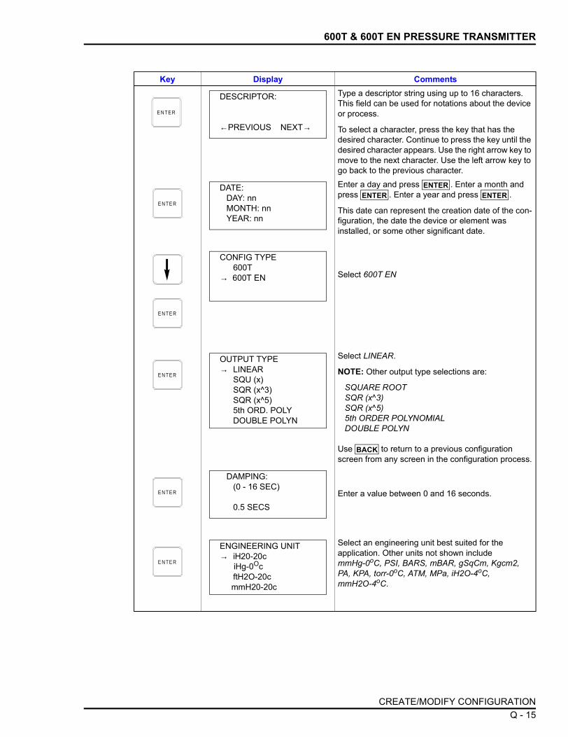
600T & 600T EN PRESSURE TRANSMITTER
Type a descriptor string using up to 16 characters. This field can be used for notations about the device or process.
To select a character, press the key that has the desired character. Continue to press the key until the desired character appears. Use the right arrow key to move to the next character. Use the left arrow key to go back to the previous character.Enter a day and press . Enter a month and press . Enter a year and press .
This date can represent the creation date of the con-figuration, the date the device or element was installed, or some other significant date.
Select 600T EN
Select LINEAR.
NOTE: Other output type selections are:
SQUARE ROOT SQR (x^3) SQR (x^5) 5th ORDER POLYNOMIAL DOUBLE POLYN
Use to return to a previous configuration screen from any screen in the configuration process.
Enter a value between 0 and 16 seconds.
Select an engineering unit best suited for the application. Other units not shown include mmHg-0oC, PSI, BARS, mBAR, gSqCm, Kgcm2, PA, KPA, torr-0oC, ATM, MPa, iH2O-4oC, mmH2O-4oC.
Key Display Comments
E N TE R
DESCRIPTOR:
←PREVIOUS NEXT→
E N TE R
DATE:DAY: nnMONTH: nnYEAR: nn
ENTERENTER ENTER
E N TE R
CONFIG TYPE600T
→ 600T EN
E N TE R
OUTPUT TYPE→ LINEAR
SQU (x)SQR (x^3)SQR (x^5)5th ORD. POLYDOUBLE POLYN
BACK
E N TE R
DAMPING:(0 - 16 SEC)
0.5 SECS
E N TE R
ENGINEERING UNIT→ iH20-20c iHg-0Oc
ftH2O-20c mmH20-20c
CREATE/MODIFY CONFIGURATION Q - 15

600T & 600T EN PRESSURE TRANSMITTER
Input lower range value using the number keys, then press . Input the upper range value, then press .
Select the 600T EN TEMPERATURE UNITS.Use arrow key to select option, then press
.
Select YES.
Key Display Comments
E N TE R
LOWER RANGE VALnn.nn UNITS
UPPER RANGE VALnn.nn UNITS
ENTERENTER
E N TE R
TEMPERATURE UNITS
→ °C °F °R °K ENTER
E N TE R
STORE THIS CONFIGURATION?
NO→ YES
E N TE R
ID TAGNAME
READY
CREATE/MODIFY CONFIGURATIONQ - 16

600T & 600T EN PRESSURE TRANSMITTER
CALIBRATION
This section details the 600T EN pressure transmitter calibration func-tions using an STT04 terminal. There are four types of calibrationfunctions:
• Sensor Trim• D-to-A adjust (Analog Mode only)• PV Bias• Set Output %
Refer to Figure Q-2 for an overview of the calibration functions.
Figure Q-2. Calibration Flowchart (600T EN)
CALIBRATION Q - 17

600T & 600T EN PRESSURE TRANSMITTER
Sensor Trim
This procedure allows calibration of the pressure sensors for 600TEN pressure transmitters. Selections available are FULL TRIM,ZERO TRIM, FACTORY TRIM and STATIC TRIM.
FULL TRIM
Use this option if both LOW (min.) and HIGH (max.) pressure settingsare to be calibrated.
Key Display Comments
This operation will cause a change in output not cor-responding to the input. Be sure the control loop is in manual.
Select YES.
Select SENSOR TRIM, or select calibration option with down-arrow key and refer to the appropriate section. Press when done.
Select FULL TRIM.
Enter the low calibration pressure value using the number keys and press . Similarly, enter the high calibration pressure value, then press .
Apply the low calibration pressure to the input of transmitter as specified earlier.
Apply the high calibration pressure to the input of transmitter as specified earlier.
C A LI- B R ATE
E N TE R
OUTPUT WILL BEAFFECTED! PROCEED?
NO→ YES
E N TE R
→ SENSOR TRIMD-TO-A ADJUSTPV BIAS
SET OUTPUT % ENTER
E N TE R
→ FULL TRIMZERO TRIMFACTORY TRIM
STATIC TRIM
E N TE R
LOW CALIB PRESSUREnn.nn UNITS
HIGH CALIB PRESSUREnn.nn UNITS
ENTERENTER
E N TE R
APPLY PRESSURE OF nn.nn UNITS
THEN HIT ENTER
E N TE R
APPLY PRESSURE OFnn.nn UNITS
THEN HIT ENTER
CALIBRATIONQ - 18

600T & 600T EN PRESSURE TRANSMITTER
ZERO TRIM
Use this option if only the LOW (min.) pressure setting is to be cali-brated
Key Display Comments
This operation will cause a change in output not cor-responding to the input. Be sure the control loop is in manual.
Select YES.
Select SENSOR TRIM, or select calibration option with down-arrow key and refer to the appropriate section. Press when done.
Select ZERO TRIM.
Apply the pressure equal to the zero value of the instrument and press .
The instrument reads the pressure applied and dis-plays its value. Press .
C A LI- B R ATE
E N TE R
OUTPUT WILL BEAFFECTED! PROCEED?
NO→ YES
E N TE R
→ SENSOR TRIMD-TO-A ADJUSTPV BIAS
SET OUTPUT % ENTER
E N TE R
FULL TRIM→ ZERO TRIM
FACTORY TRIM STATIC TRIM
E N TE R
APPLY 0 INPUTTO SENSOR
THEN HIT ENTERENTER
E N TE R
APPLIED ZERO INPUT:value units
PRESS ENTERTO CONTINUE
ENTER
E N TE R
ID TAGNAME
READY
CALIBRATION Q - 19

600T & 600T EN PRESSURE TRANSMITTER
FACTORY TRIM
Use this option if factory setting is to be used for calibration.
Key Display Comments
This operation will cause a change in output not cor-responding to the input. Be sure the control loop is in manual.
Select YES.
Select SENSOR TRIM, or select calibration option with down-arrow key and refer to the appropriate section. Press when done.
Select FACTORY TRIM.
C A LI- B R ATE
E N TE R
OUTPUT WILL BEAFFECTED! PROCEED?
NO→ YES
E N TE R
→ SENSOR TRIMD-TO-A ADJUSTPV BIAS
SET OUTPUT % ENTER
E N TE R
FULL TRIMZERO TRIM
→ FACTORY TRIM STATIC TRIM
E N TE R
ID TAGNAME
READY
CALIBRATIONQ - 20

600T & 600T EN PRESSURE TRANSMITTER
STATIC TRIM
Use this option if the instrument is to be statically calibrated using aknown pressure.
Key Display Comments
This operation will cause a change in output not cor-responding to the input. Be sure the control loop is in manual.
Select YES.
Select SENSOR TRIM, or select calibration option with down-arrow key and refer to the appropriate section. Press when done.
Select STATIC TRIM.
Display shows the value of the pressure measured by the 600T EN transmitter.
Enter the value of the actual static pressure using the number keys.
C A LI- B R ATE
E N TE R
OUTPUT WILL BEAFFECTED! PROCEED?
NO→ YES
E N TE R
→ SENSOR TRIMD-TO-A ADJUSTPV BIAS
SET OUTPUT % ENTER
[ 3 TIMES ]
E N TE R
FULL TRIM ZERO TRIM
FACTORY TRIM→ STATIC TRIM
E N TE R
STATIC PRESSUREvalue units
PRESS ENTER TO MODIFY
E N TE R
STATIC PRESSURE
value units
E N TE R
ID TAGNAME
READY
CALIBRATION Q - 21

600T & 600T EN PRESSURE TRANSMITTER
D-to-A Adjust
The D-TO-A ADJUST selection is only present when you are in theANALOG communication mode. There are three methods availableto adjust the four to 20 milliampere output:
• Up/Down Arrow keys. • Meter value entry for HART devices.• Factory DAC Trim
ARROW KEY ADJUSTMENT
Use this function to adjust the 4 to 20 milliampere output of the fielddevice using the up and down arrow keys.
Key Display CommentsThis operation will cause a change in output not cor-responding to the input. Be sure the control loop is in manual.
Select YES.
Select D-TO-A ADJUST.
Select UPDOWN ARROW KEYS.
Use the arrow keys to adjust the 4 mA signal.
NOTE: When increasing or decreasing the mA sig-nal, the increments of change increase with succes-sive depressions until the maximum level of change is reached. By changing direction you will return to the smallest increment of change. This adjustment technique speeds up the adjustment process without affecting fine adjustment.
C A LI- B R ATE
OUTPUT WILL BEAFFECTED! PROCEED?
NO→ YES
E N TE R
CALIBRATION SENSOR TRIM
→ D-TO-A ADJUSTPV BIAS
SET OUTPUT %
E N TE R
D/A CAL USING→ UPDOWN ARROW KEYS
METER VALUE ENTRY
E N TE R
ADJUST TO 4 mA
THEN HIT ENTER
CALIBRATIONQ - 22

600T & 600T EN PRESSURE TRANSMITTER
METER VALUE ADJUSTMENT
Use this function to adjust the four to 20 milliampere output of the fielddevice using values from an external current meter. This method isonly valid for HART devices.
Use the arrow keys to adjust the 20 mA signal.
Key Display Comments
E N TE R
ADJUST TO 20 mA
THEN HIT ENTER
E N TE R
ID TAGNAME
READY
Key Display CommentsThis operation will cause a change in output not cor-responding to the input. Be sure the control loop is in manual.
Select YES.
Select D-TO-A ADJUST.
Select METER VALUE ENTRY.
C A LI- B R ATE
E N TE R
OUTPUT WILL BEAFFECTED! PROCEED?
NO→ YES
E N TE R
CALIBRATION SENSOR TRIM
→ D-TO-A ADJUSTPV BIAS
SET OUTPUT %
E N TE R
D/A CAL USINGUPDOWN ARROW
KEYS→ METER VALUE ENTRY
CALIBRATION Q - 23

600T & 600T EN PRESSURE TRANSMITTER
PV Bias
The PV Bias calibration procedure allows you to align the "zero" ofthe process with the "zero" reading of the transmitter. This may bedone in one of two ways:
• Apply a pressure that corresponds to the desired zero offset orbias [SET PV ZERO]
• To scale to a value different from zero, calculate the offset orbiasand apply it to the 600T EN [SET PV VAL]
Use the number keys to enter the current meter reading.
Use the number keys to enter the current meter reading.
Key Display Comments
E N TE R
4 mA CALIBRATION:
ENTER METER VALUE n.nnnn
E N TE R
20 mA CALIBRATION:
ENTER METER VALUE nn.nnnn
E N TE R
ID TAGNAME
READY
Key Display Comments
This operation will cause a change in output not cor-responding to the input. Be sure the control loop is in manual.
Select YES.
C A LI- B R ATE
E N TE R
OUTPUT WILL BEAFFECTED! PROCEED?
NO→ YES
CALIBRATIONQ - 24

600T & 600T EN PRESSURE TRANSMITTER
Select PV BIAS.
If digitally configured, the D-TO-A ADJUST selection will not appear.
Use the arrow keys to scroll to the desired PV BIAS parameter. RESET removes any previously config-ured bias values. The following procedure is used to establish the zero offset for SET PV ZERO, the pro-cedure for SET PV VAL is similar.
Apply the desired zero pressure value to the trans-mitter. Scroll to SET PV ZERO using the down arrow key and press .
Pressing calibrates the PV ZERO value.
SET PV ZERO is complete.
Key Display Comments
E N TE R
CALIBRATION SENSOR TRIM
D-TO-A ADJUST→ PV BIAS SET OUTPUT %
E N TE R
PV BIAS→ RESET
SET PV ZEROSET PV VAL
E N TE R
PV BIASRESET
→ SET PV ZEROSET PV VAL ENTER
E N TE R
PV VALUE READ: value unitsPRESS ENTERTO SET PV ZERO
ENTER
E N TE R
ID TAGNAME
READY
CALIBRATION Q - 25

600T & 600T EN PRESSURE TRANSMITTER
Set Output %
Key Display CommentsThis operation will cause a change in output not cor-responding to the input. Be sure the control loop is in manual.
Select YES.
Select SET OUTPUT %.
If digitally configured, the D-TO-A ADJUST selection will not appear.
Select LOW and press . (Procedure for HIGH selection is identical).
Display indicates present data.
Enter LOW value, .
C A LI- B R ATE
E N TE R
OUTPUT WILL BEAFFECTED! PROCEED?
NO→ YES
[ 3 TIMES ]
E N TE R
CALIBRATION SENSOR TRIM
D-TO-A ADJUSTPV BIAS
→ SET OUTPUT %
E N TE R
SET OUTPUT %→ LOW
HIGHENTER
E N TE R
OP %: nnn.nn %PV VAL:
value unitsHit ENTER to set OP%
E N TE R
ENTER NEW VALUE
value % ENTER
E N TE R
ID TAGNAME
READY
CALIBRATIONQ - 26

Worksheet STT04
AVS Smart Positioner ConfigurationIDTAG (≤14 digits, alphanumeric)
MODE Analog Digital ____ Channel Number
INPUT CHARACTERISTICS Linear Square root Square
Equal % Function Generator Quick act
FUNCTION GENERATOR Input Output
_______%
_______%
_______%
_______%
_______%
_______%
_______%
_______%
_______%
_______%
_______%
Point 0
Point 1
Point 2
Point 3
Point 4
Point 5
Point 6
Point 7
Point 8
Point 9
Point 10
_______%
_______%
_______%
_______%
_______%
_______%
_______%
_______%
_______%
_______%
_______%
Point 0
Point 1
Point 2
Point 3
Point 4
Point 5
Point 6
Point 7
Point 8
Point 9
Point 10
LOWER RANGE VALUE _______ Specified LRV _______ LRV
UPPER RANGE VALUE _______ Specified URV _______ URV
VALVE STUCK ALARM Yes No
PRESSURE UNITS psi bars
PID PARAMETERS Kp Ki Kd
INPUT SIGNAL Normal act Reverse act
DAMPING ______ sec (0.001 to 32.00 sec)
ALARMS ______ Deviation alarm ______ Low pressure alarm ______ High pressure alarm
LOW FLOW SHUT OFF ______ %
DO3 ACTION Lo pressure Deviation alarm Valve stuck alarm Status
NOTES:1. Default parameters.

Worksheet STT04
BCN Smart Electronic Pressure Transmitter ConfigurationIDTAG (≤14 digits, alphanumeric)
MODE Analog Digital ____ Channel Number
OUTPUT TYPE Linear1
5/2 Flow Mode
Function Generator
Square root
Vol./Sphere
3/2 Flow Mode
Vol./Cylinder
FUNCTION GENERATOR
Input _______%
_______%
_______%
_______%
_______%
_______%
Point 0
Point 1
Point 2
Point 3
Point 4
Point 5
Output _______%
_______%
_______%
_______%
_______%
_______%
Point 0
Point 1
Point 2
Point 3
Point 4
Point 5
OUTPUT ACTION Normal1 Reverse
DAMPING _______ sec (0.001 to 32.00 sec)
ENGINEERING UNITS iH2O1 mmHG cmH2O
psi MPA kPa
BARS mBARS kg/cm2
LOWER RANGE VALUE _______ Specified LRV
UPPER RANGE VALUE _______ Specified URV
INITIALIZE MODE2 Low High
FAIL MODE2 Low High Last
SECONDARY UNITS _______ Secondary LRV
_______ Secondary URV
NOTES:1. Default parameters.2. Select to maintain safe operation during start-up and diagnostically detected failures of the transmitter.
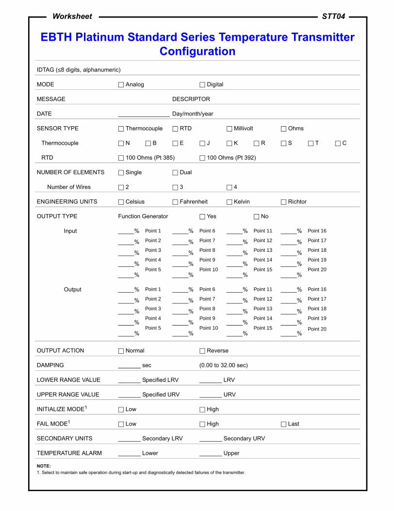
Worksheet STT04
EBTH Platinum Standard Series Temperature Transmitter Configuration
IDTAG (≤8 digits, alphanumeric)
MODE Analog Digital
MESSAGE DESCRIPTOR
DATE ________________ Day/month/year
SENSOR TYPE Thermocouple RTD Millivolt Ohms
Thermocouple N B E J K R S T C
RTD 100 Ohms (Pt 385) 100 Ohms (Pt 392)
NUMBER OF ELEMENTS Single Dual
Number of Wires 2 3 4
ENGINEERING UNITS Celsius Fahrenheit Kelvin Richtor
OUTPUT TYPE Function Generator Yes No
Input _____%
_____%
_____%
_____%
_____%
Point 1
Point 2
Point 3
Point 4
Point 5
_____%
_____%
_____%
_____%
_____%
Point 6
Point 7
Point 8
Point 9
Point 10
_____%
_____%
_____%
_____%
_____%
Point 11
Point 12
Point 13
Point 14
Point 15
_____%
_____%
_____%
_____%
_____%
Point 16
Point 17
Point 18
Point 19
Point 20
Output _____%
_____%
_____%
_____%
_____%
Point 1
Point 2
Point 3
Point 4
Point 5
_____%
_____%
_____%
_____%
_____%
Point 6
Point 7
Point 8
Point 9
Point 10
_____%
_____%
_____%
_____%
_____%
Point 11
Point 12
Point 13
Point 14
Point 15
_____%
_____%
_____%
_____%
_____%
Point 16
Point 17
Point 18
Point 19
Point 20
OUTPUT ACTION Normal Reverse
DAMPING _______ sec (0.00 to 32.00 sec)
LOWER RANGE VALUE _______ Specified LRV _______ LRV
UPPER RANGE VALUE _______ Specified URV _______ URV
INITIALIZE MODE1 Low High
FAIL MODE1 Low High Last
SECONDARY UNITS _______ Secondary LRV _______ Secondary URV
TEMPERATURE ALARM _______ Lower _______ Upper
NOTE:1. Select to maintain safe operation during start-up and diagnostically detected failures of the transmitter.

Worksheet STT04
EQN Smart Electronic Temperature Transmitter Configuration
IDTAG (≤14 digits, alphanumeric)
MODE Analog Digital ____ Channel Number
SENSOR TYPE
Thermocouple N B E J K R S T C
RTD 100 Ohms (Pt 385) 100 Ohms (Pt 392)
Type 2-wire 3-wire Dual
MILLIVOLT
OHMS 2-wire 3-wire Dual
OUTPUT TYPE
Function Generator Yes No
Input _______%
_______%
_______%
_______%
_______%
Point 1
Point 2
Point 3
Point 4
Point 5
Output _______%
_______%
_______%
_______%
_______%
Point 1
Point 2
Point 3
Point 4
Point 5
OUTPUT ACTION Normal1 Reverse
DAMPING _______ sec (0.001 to 32.00 sec)
ENGINEERING UNITS2 Celsius Fahrenheit Kelvin
LOWER RANGE VALUE _______ Specified LRV _______ LRV
UPPER RANGE VALUE _______ Specified URV _______ URV
INITIALIZE MODE3 Low High
FAIL MODE3 Low High Last
NOTES:1. Default parameters.2. Not applicable in millivolt mode.3. Select to maintain safe operation during start-up and diagnostically detected failures of the transmitter.

Worksheet STT04
EQS Platinum Standard Series Smart Temperature Transmitter Configuration
IDTAG (≤14 digits, alphanumeric)
MODE Analog Digital ____ Channel Number
TRANSMITTER MODE Thermocouple RTD Millivolt Ohms
Thermocouple N B E J K R S T C
RTD 100 Ohms (pt 385) 100 Ohms (pt 392)
NUMBER OF ELEMENTS Single Dual
Number of Wires 2 3 4
ENGINEERING UNITS Celsius Fahrenheit Kelvin
OUTPUT TYPE
Function Generator Yes No
Input _______%
_______%
_______%
_______%
_______%
Point 1
Point 2
Point 3
Point 4
Point 5
Output _______%
_______%
_______%
_______%
_______%
Point 1
Point 2
Point 3
Point 4
Point 5
OUTPUT ACTION Normal Reverse
DAMPING _______ sec (0.00 to 32.00 sec)
LOWER RANGE VALUE _______ Specified LRV _______ LRV
UPPER RANGE VALUE _______ Specified URV _______ URV
INITIALIZE MODE2 Low High
FAIL MODE2 Low High Last
SECONDARY UNITS _______ Secondary LRV _______ Secondary URV
TEMPERATURE ALARM _______ Lower _______ Upper
NOTES:1. Default parameters.2. Select to maintain safe operation during start-up and diagnostically detected failures of the transmitter.

Worksheet STT04
PTH Smart Electronic Pressure Transmitter ConfigurationIDTAG (≤8 digits, alphanumeric)
MODE Analog Digital ____ Channel number
MESSAGE DESCRIPTOR
DATE ________________ Day/month/year
OUTPUT TYPE Linear1
Vol./sphere
Square root
Vol./cylinder
3/2 flow mode
Function generator
5/2 flow mode
FUNCTION GENERATOR
Input _______%
_______%
_______%
_______%
_______%
_______%
Point 0
Point 1
Point 2
Point 3
Point 4
Point 5
Output _______%
_______%
_______%
_______%
_______%
_______%
Point 0
Point 1
Point 2
Point 3
Point 4
Point 5
OUTPUT ACTION Normal1 Reverse
DAMPING _______ sec (0.001 to 32.00 sec)
ENGINEERING UNITS iH2O1 mmH2O mmHg psi BARS
mBARS kg/cm2 kPa
LOWER RANGE VALUE _______ Specified LRV
UPPER RANGE VALUE _______ Specified URV
INITIALIZE MODE2 Low High
FAIL MODE2 Low High Last
SECONDARY UNITS _______ Secondary LRV _______ Secondary URV
TEMPERATURE ALARM _______ Lower _______ Upper
NOTES:1. Default parameters.2. Select to maintain safe operation during start-up and diagnostically detected failures of the transmitter.

Worksheet STT04
PTS Smart Electronic Pressure Transmitter ConfigurationIDTAG (≤14 digits, alphanumeric)
MODE Analog Digital ____ Channel number
OUTPUT TYPE Linear1
Vol./sphere
Square root
Vol./cylinder
3/2 flow mode
Function generator
5/2 flow mode
FUNCTION GENERATOR
Input _______%
_______%
_______%
_______%
_______%
_______%
Point 0
Point 1
Point 2
Point 3
Point 4
Point 5
Output _______%
_______%
_______%
_______%
_______%
_______%
Point 0
Point 1
Point 2
Point 3
Point 4
Point 5
OUTPUT ACTION Normal1 Reverse
DAMPING _______ sec (0.001 to 32.00 sec)
ENGINEERING UNITS iH2O1 mmHg cmH2O psi MPA
kPa BARS mBARS kg/cm2
LOWER RANGE VALUE _______ Specified LRV
UPPER RANGE VALUE _______ Specified URV
INITIALIZE MODE2 Low High
FAIL MODE2 Low High Last
SECONDARY UNITS _______ Secondary LRV _______ Secondary URV
TEMPERATURE ALARM _______ Lower _______ Upper
NOTES:1. Default parameters.2. Select to maintain safe operation during start-up and diagnostically detected failures of the transmitter.

Worksheet STT04
TBN480 Smart Conductivity Transmitter Configuration
IDTAG (≤14 digits, alphanumeric)
MODE Analog Digital ____ Channel Number
ANALYZER TYPE General Pure H2O Cond. Concentration
SENSOR GROUP A B C
RANGE JUMPER High Medium Low
ANALYZER RANGE 0-99.9 µS/cm 0-9.99 µS/cm
TEMP. COMP. INPUT Manual 3.01k Balco
DAMPING _______ sec (0.001 to 32.00 sec)
LOWER RANGE VALUE _______ Specified LRV _______ LRV
UPPER RANGE VALUE _______ Specified URV _______ URV
INITIALIZE MODE2 Low High
FAIL MODE2 Low High Last
DIAG. SPIKE OUTPUT No Yes
NOTES:1. Default parameters.2. Select to maintain safe operation during start-up and diagnostically detected failures of the transmitter.

Worksheet STT04
TBN580 Smart pH Transmitter ConfigurationIDTAG (≤14 digits, alphanumeric)
MODE Analog Digital ____ Channel Number
pH SENSOR INPUT Standard Antimony
TEMP. COMP. INPUT 3.01k Balco None (manual)
TEMPERATURE DISPLAY C° F°
OUTPUT TYPE
Function Generator Yes No
Input _______%
_______%
_______%
_______%
_______%
Point 1
Point 2
Point 3
Point 4
Point 5
Output _______%
_______%
_______%
_______%
_______%
Point 1
Point 2
Point 3
Point 4
Point 5
OUTPUT ACTION Normal1 Reverse
DAMPING _______ sec (0.001 to 32.00 sec)
LOWER RANGE VALUE _______ Specified LRV _______ LRV
UPPER RANGE VALUE _______ Specified URV _______ URV
INITIALIZE MODE2 Low High
FAIL MODE2 Low High Last
SECONDARY UNITS _______ Secondary LRV
_______ Secondary URV
NOTES:1. Default parameters.2. Select to maintain safe operation during start-up and diagnostically detected failures of the transmitter.

Worksheet STT04
TBN581 Smart ORP/pION Transmitter ConfigurationIDTAG (≤14 digits, alphanumeric)
MODE Analog Digital ____ Channel Number
OUTPUT TYPE
Function Generator Yes No
Input _______%
_______%
_______%
_______%
_______%
Point 1
Point 2
Point 3
Point 4
Point 5
Output _______%
_______%
_______%
_______%
_______%
Point 1
Point 2
Point 3
Point 4
Point 5
OUTPUT ACTION Normal1 Reverse
DAMPING _______ sec (0.001 to 32.00 sec)
LOWER RANGE VALUE _______ Specified LRV _______ LRV
UPPER RANGE VALUE _______ Specified URV _______ URV
INITIALIZE MODE2 Low High
FAIL MODE2 Low High Last
SECONDARY UNITS _______ Secondary LRV
_______ Secondary URV
NOTES:1. Default parameters.2. Select to maintain safe operation during start-up and diagnostically detected failures of the transmitter.

Worksheet STT04
XM/SM/XE Magnetic Flowmeter ConfigurationIDTAG (≤14 digits, alphanumeric)
MODE Analog Digital ____ Channel Number
FLOW DIRECTION Normal Reverse
DAMPING _______ sec (0.001 to 32.00 sec)
SELECT PV EU 1/s 1/m 1/h m3/s m3/m
m3/h gal/s gal/m gal/h User defined
RANGE DN _______ PV EU
EU DESCRIPTOR _____________________
EU FACTOR ______________
TIME RELATION Per sec Per min Per hour
DENSITY FACTOR _____________________
RANGE VALUE 1 _______ Units
RANGE VALUE 2 _______ Units
FAIL MODE2 Low High
SELECT TOTALIZER EU 1 m3 gal User defined
PULSE FACTOR ______________
PULSE WIDTH ______________
LOW FLOW CUTOFF ______________ %
DIGITAL FILTER On Off
RESPONSE TIME Normal Fast
RANGE CONFIGURATION 2-fwd 1-fwd, 1-rev
FLOW DIRECTION Fwd and rev Fwd only
UPPER PV ALARM ______________ Units
EMPTY PIPE DET On Off
LOWER PV ALARM ______________ Units
NOTES:1. Default parameters.2. Select to maintain safe operation during start-up and diagnostically detected failures of the transmitter.

Worksheet STT04
TZID/AZH Positioner ConfigurationSTT04 CONFIGURATION (ID tag up to 8 ASCII characters)
MODE Analog Digital ____ Channel number
TAG NUMBER
DESCRIPTOR
POSITIONING TASK
DATE ________________ Day/month/year
SET POINT UNITS
LOW SET POINT RANGE HIGH SET POINT RANGE
CHARACTERISTIC CURVE Linear Equal % 1:25 Equal % 1:50
Equal % 25:1 Equal % 50:1 User defined
VALVE ACTION Direct Reverse
DEAD BAND_____%
MINIMUM STROKE RANGE _____%
MAXIMUM STROKE RANGE _____%
SHUT-OFF VALUE _____%
DEADBAND TIME LIMIT _____ sec.
ADJUSTED TIME, UP _____ sec. ADJUSTED TIME, DOWN _____ sec.
LOW ALARM LIMIT _____ sec. HIGH ALARM LIMIT _____ sec.

Worksheet STT04
TB82 Transmitter ConfigurationTRANSMITTER TYPE pH pION ORP CONC
STT04 CONFIGURATION (ID tag up to 8 ASCII characters)
MODE Analog Digital ____ Channel number
MESSAGE DESCRIPTOR
DATE ________________ Day/month/year
OUTPUT TYPE Linear Function Generator
Input 0____%
_____%
_____%
_____%
_____%
Point 1
Point 2
Point 3
Point 4
Point 5
_____%
_____%
_____%
_____%
_____%
Point 6
Point 7
Point 8
Point 9
Point 10
_____%
_____%
_____%
_____%
_____%
Point 11
Point 12
Point 13
Point 14
Point 15
_____%
_____%
_____%
_____%
100 %
Point 16
Point 17
Point 18
Point 19
Point 20
Output 0____%
_____%
_____%
_____%
_____%
Point 1
Point 2
Point 3
Point 4
Point 5
_____%
_____%
_____%
_____%
_____%
Point 6
Point 7
Point 8
Point 9
Point 10
_____%
_____%
_____%
_____%
_____%
Point 11
Point 12
Point 13
Point 14
Point 15
_____%
_____%
_____%
_____%
100 %
Point 16
Point 17
Point 18
Point 19
Point 20
DAMPING _______ sec (0.001 to 100.00 sec)
LOWER RANGE VALUE _______
UPPER RANGE VALUE _______
TEMP. COMPENSATION TYPE (TB82 pH only) Manual Automatic Auto Sol. (Advance mode)
TEMPERATURE (TB82 pH with Manual Temp. Comp) ________ UNITS
NOTE:1. Default parameters.

Index
AAdding a user .............................................................O-1Auto shutoff ................................................................ 4-3AVS calibration function .............................................A-5
BBatteries .............................................................. 1-4, 3-2Battery charger ........................................................... 3-2Battery pack replacement........................................... 6-2
CCalibration
AVS.......................................................................A-5Automatic ........................................................A-9Input A/D .........................................................A-7Manual ............................................................A-8Output D/A ......................................................A-6
BCN ......................................................................G-5Bench..............................................................G-5D/A..................................................................G-9Rezero ............................................................G-8
EBTH ....................................................................B-5Bench..............................................................B-6D/A..................................................................B-7
EQN......................................................................H-4Bench..............................................................H-5D/A..................................................................H-7
EQS ......................................................................C-4Bench..............................................................C-4D/A..................................................................C-7
MagFlow ................................................................ I-5Bench............................................................... I-6D/A................................................................... I-7Empty pipe detector ......................................... I-6
PTH......................................................D-5, P-5, 1-17Bench.............................................D-6, P-6, 1-18D/A.................................................D-8, P-7, 1-22Rezero ...........................................D-8, P-9, 1-24
PTS.......................................................................E-4Bench..............................................................E-4D/A..................................................................E-8Rezero ............................................................E-7
TB82 .....................................................................N-4pH calibration ..................................................N-4pH calibration, one point .................................N-5pH calibration, two point..................................N-6Temperature calibration ..................................N-8
TBN480..................................................................J-5Process conductivity .................................J-5, J-6Process temperature........................................J-7
TBN580 ................................................................ K-5Bench, pH....................................................... K-7Bench, temperature...................................... K-10D/A ............................................................... K-11Process .......................................................... K-6
TBN581 .................................................................L-4A/D ..................................................................L-9Bench, mV.......................................................L-8Bench, ORP/pION ...........................................L-6Process ...........................................................L-5
TZID/AZH .............................................................M-5Auto stroke .....................................................M-5Lever zero position .........................................M-7Manual range adjustment ...............................M-6Spring action actuator ....................................M-8
Calibration flowchartsAVS ...................................................................... A-5BCN...................................................................... G-5EBTH.................................................................... B-5EQN ..................................................................... H-5EQS...................................................................... C-5MagFlow................................................................. I-6PTH ..................................................... D-5, P-5, 1-17PTS ...................................................................... E-5TB82..................................................................... N-4TBN480 ................................................................. J-5TBN580 ................................................................ K-5TBN581 .................................................................L-5TZID/AZH .............................................................M-5
Cancel fix output .......................................................4-12Change STT04 name............................................... O-12Charging STT04..........................................................3-2Cleaning......................................................................7-1Clip leads
Installation .............................................................3-2Removal ................................................................3-3
Codes (TB82)Error ................................................................... N-23Problem.............................................................. N-17
CommunicationFSK .......................................................................2-1HART ....................................................................2-1Point-to-point .........................................................2-1
Communication format..............................................4-22Configuration
AVS ...................................................................... A-1BCN...................................................................... G-1Download to STT04 ............................................4-25EBTH.................................................................... B-1EQN ..................................................................... H-1EQS...................................................................... C-1HART universal .....................................................F-1
Index - 1

Index (continued)
MagFlow.................................................................I-1PTH ..................................................... D-1, P-1, 1-13PTS ...................................................................... E-1TB82..................................................................... N-1TBN480 ................................................................. J-1TBN580 ................................................................ K-1TBN581 .................................................................L-1TZID/AZH .............................................................M-1Upload from STT04.............................................4-25
Configuration flowchartsBCN......................................................................G-1EQN...................................................................... H-1EQS...................................................................... C-1HART.....................................................................F-1MagFlow.................................................................I-1PTH ..................................................... D-1, P-1, 1-13PTS ...................................................................... E-1TB82..................................................................... N-1TBN480 ................................................................. J-1TBN580 ................................................................ K-1TBN581 .................................................................L-1TZID/AZH .............................................................M-1
Configuration storage capacity....................................1-4
DDevice status.............................................................4-19Digital field bus............................................................2-1Digital field bus wiring .................................................2-2Documentation............................................................8-1Download configuration to STT04.............................4-25Downloading
Configurations .............................................4-25, O-8Upgrades...............................................................6-3
D-to-A AdjustEBTH.................................................................... B-7PTH ..................................................... D-8, P-7, 1-22
EEditing calibration constants
Conductivity........................................................... J-8Temperature.......................................................... J-9
Erase configuration procedure ..................................4-10Error codes, TB82.................................................... N-23Error messages...........................................................5-1Errors
FSK devices ..........................................................5-5HART devices .......................................................5-2
Exit utilities software...................................................O-7
FField bus ..................................................................... 2-1Field bus wiring........................................................... 2-2Firmware level ..................................................... 1-1, 1-3Firmware upgrades..................................................... 6-3Fix output.................................................................. 4-12Flowcharts
CalibrationAVS.................................................................A-5BCN................................................................ G-5EBTH...............................................................B-5EQN ................................................................H-5EQS.................................................................C-5MagFlow........................................................... I-6PTH................................................D-5, P-5, 1-17PTS .................................................................E-5TB82................................................................N-4TBN480........................................................... J-5TBN580...........................................................K-5TBN581........................................................... L-5TZID/AZH....................................................... M-5
ConfigurationBCN................................................................ G-1EBTH...............................................................B-1EQN ................................................................H-1EQS.................................................................C-1HART .............................................................. F-1MagFlow........................................................... I-1PTH................................................D-1, P-1, 1-13PTS .................................................................E-1TB82................................................................N-1TBN480........................................................... J-1TBN580...........................................................K-1TBN581........................................................... L-1TZID/AZH....................................................... M-1
Frequency shift keying................................................ 2-1FSK device errors....................................................... 5-5Functional operation ................................................... 2-1
GGet configuration procedure ....................................... 4-8
HHART.......................................................................... F-1
Communications ................................................... 2-1Device errors ........................................................ 5-2Universal configuration procedure ........................ F-1Wiring............................................................. 2-2, 3-3
How to use instruction book ....................................... 1-2
Index - 2

Index (continued)
IInitial start-up.............................................................. 4-3Installation of utilities software.................................... 3-4Installing clip leads ..................................................... 3-2
LLanguage ................................................................. 4-21LCD setup ................................................................ 4-13
MMagFlow calibration function....................................... I-5MagFlow configuration functions................................. I-1Maintenance............................................................... 7-1Messages, error ......................................................... 5-1Monitor key
Monitor output..................................................... 4-17Monitor secondary output ................................... 4-18
Monitor key (AVS)Air pressure ........................................................A-13Deviation.............................................................A-13Digital input .........................................................A-13Input air supply (O1) ...........................................A-13Output air supply.................................................A-13Output air supply (O2) ........................................A-13Position...............................................................A-13Reverse ..............................................................A-13Temperature .......................................................A-13Travel..................................................................A-13
Monitor output ................................................. 4-16, 4-17Monitor secondary output ......................................... 4-18
NName, STT04 .................................................. 4-23, 4-24New database ............................................................O-6Nomenclature ............................................................. 1-3
OOpen database...........................................................O-7Operational functions ............................................... 4-11Operator/interface controls ......................................... 4-1Options and accessories ............................................ 1-4Options key functions ............................................... 4-21
Battery charge .................................. 4-22, 4-23, 4-24Communications format...................................... 4-22Language............................................................ 4-21
Output keyMonitor output..................................................... 4-16Temperature ....................................................... 4-18
PPhysical operation................................................2-1, 3-1Point-to-point communication .....................................2-1Problem codes, TB82 .............................................. N-17PTH calibration procedures ...................... D-5, P-5, 1-17PTS calibration procedures........................................ E-4
RRecommended spare parts.........................................6-5Reference documents......................................... 1-3, E-1Remote mode ............................................................ O-9Removing clip leads....................................................3-3Replacement parts......................................................8-1Report diagnostics ................................................... O-13Rerange procedure ...................................................4-19
SSecurity ...................................................................... O-1Set COM port ........................................................... O-13Spare parts
Recommended......................................................6-5Replacement .........................................................8-1
Special feature key ...................................................4-12Fix output/cancel fix output .................................4-12LCD setup ...........................................................4-13Standard configuration ........................................4-14
Special handling..........................................................6-1Standard configuration..............................................4-14Start utilities software................................................. O-6Status check .............................................................4-19STT04 cleaning...........................................................7-1STT04 name ....................................................4-23, 4-24STT04 upgrades .........................................................6-4Support services .........................................................8-1
TTB82 calibration procedures ...................................... N-4TBN480
Calibration procedures .......................................... J-5Reset to factory configuration ............................. J-11
TBN580Calibration procedures ......................................... K-5
TBN581Calibration procedures ..........................................L-4
Technical documentation ............................................8-1Temperature function................................................4-18Temperature limits ......................................................1-4Test communications ............................................... O-11Training .......................................................................8-1
Index - 3

Index (continued)
Transfer configurations ..............................................O-8Troubleshooting ..........................................................5-1TZID/AZH calibration procedures...............................M-5
UUpgrade
Boot code ...........................................................O-13Firmware ............................................................O-13
Upgrade firmware........................................................6-3Upload configuration from STT04 .............................4-25Utilities software ........................................................4-25
Adding a user .......................................................O-1Change STT04 name.........................................O-12Description ............................................................3-4Download to STT04............................................O-10Downloading configurations ................................4-25Exit .......................................................................O-7Installing ................................................................3-4New database ......................................................O-6Open database.....................................................O-7Practices................................................................3-4Report diagnostics..............................................O-13
Security................................................................ O-1Set COM port ..................................................... O-13Start ..................................................................... O-6Starting the password program............................ O-1System requirements ............................................ 3-4Test communication........................................... O-11Transfer configuration.......................................... O-8Upgrade boot code ............................................ O-13Upgrade firmware .............................................. O-13Upload from STT04 ............................................. O-9User level accessibility......................................... O-3View files of a databases ..................................... O-8View STT04 configurations.................................. O-7
VView files of a database............................................. O-8
WWiring
Field bus ............................................................... 2-2Point-to-point ................................................. 2-2, 3-3
Index - 4

The Companys policy is one of continuous product improvement and theright is reserved to modify the information contained herein without notice.
© 2002 ABB Automation Inc. Printed in USA
ABB Instrumentation S.p.AVia Sempione 24320016 Pero (Milano) ItalyTel: +39 (02) 33928 1Fax: +39 (02) 33928 240
ABB Instrumentation LtdHoward Road, St. NeotsCambs. England, PE19 3EUTel. +44 (0) 1480-475-321FAX: +44 (0) 1480-217-948
ABB Inc.Instrumentation Division125 East County Line RoadWarminster, PA 18974 USATel. 215-674-6000FAX: 215-674-7183
ABB Automation Products GmbHIndustriestr. 28D-65760 Eschborn GermanyTel: +49 (0) 6196 800 0Fax: +49 (0) 6196 800 1849
PN25
054