Embed Size (px)
Citation preview

EclipseRatio Regulators
ES Series
Instruction Manual 7425/1/2009
Version 1

2 Eclipse Ratio Regulator, V1, Instruction Manual 742, 5/1/2009
Copyright
Copyright 1997 by Eclipse, Inc. All rights reservedworldwide. This publication is protected by federalregulation and shall not be copied, distributed,transmitted, transcribed or translated into any human orcomputer language, in any form or by any means, to anythird parties, without the express written consent ofEclipse, Inc.
Disclaimer NoticeIn accordance with the manufacture’s policy of continualproduct improvement, the product presented in thisbrochure is subject to change without notice or obligation.
The material in this manual is believed adequate for theintended use of the product. If the product is used forpurposes other than those specified herein, confirmationof validity and suitability must be obtained. Eclipsewarrants that the product itself does not infringe upon anyUnited States patents. No further warranty is expressed orimplied.
Liability and WarrantyWe have made every effort to make this manual asaccurate and complete as possible. Should you find errorsor omissions, please bring them to our attention so that wemay correct them. In this way we hope to improve ourproduct documentation for the benefit of our customers.Please send your corrections and comments to ourMarketing Communications Manager.
It must be understood that Eclipse’s liability for its product,whether due to breach of warranty, negligence, strictliability, or otherwise is limited to the furnishing ofreplacement parts and Eclipse will not be liable for anyother injury, loss, damage or expenses, whether direct orconsequential, including but not limited to loss of use,income, or damage to material arising in connection withthe sale, installation, use of, inability to use, or the repairor replacement of Eclipse’s products.
Any operation expressly prohibited in this manual, anyadjustment, or assembly procedures not recommended or authorized in these instructions shall void the warranty.
Document ConventionsThere are several special symbols in this document. Youmust know their meaning and importance.
The explanation of these symbols follows below. Pleaseread it thoroughly.
How To Get HelpIf you need help, contact your local Eclipse representative.You can also contact Eclipse at:
1665 Elmwood Rd.Rockford, Illinois 61103 U.S.A.
Phone: 815-877-3031Fax: 815-877-3336
http://www.eclipsenet.com
This is the safety alert symbol. It is used to alert you to potential personal injury hazards. Obey all safety messages that follow this symbol to avoid possible injury or death.
Indicates a hazardous situation which, if not avoided, will result in death or serious injury.
Indicates a hazardous situation which, if not avoided, could result in death or serious injury.
Indicates a hazardous situation which, if not avoided, could result in minor or moderate injury.
Is used to address practices not related to personal injury.
Indicates an important part of text. Read thoroughly.NOTE
NOTICE
WARNING
CAUTION

3Eclipse Ratio Regulator, V1, Instruction Manual 742, 5/1/2009
Table of Contents
Introduction............................................................................................................................... 4Product Description.............................................................................................................. 4
Safety......................................................................................................................................... 5Safety Warnings................................................................................................................... 5Capabilities .......................................................................................................................... 5Operator Training................................................................................................................. 5Replacement Parts .............................................................................................................. 5
Specifications ........................................................................................................................... 6Compatability/Temperature Specifications .......................................................................... 6Model Specifications ............................................................................................................ 6Flow vs Pressure Drop......................................................................................................... 6Dimensions .......................................................................................................................... 7
Design & Installation ................................................................................................................ 9General Information ............................................................................................................. 9Ratio Regulator/Pipe Connections....................................................................................... 9Gas Bias Adjustment ........................................................................................................... 10

4 Eclipse Ratio Regulator, V1, Instruction Manual 742, 5/1/2009
IntroductionProduct Description
The ES-Series Ratio Regulators are used in applicationswhere gas to air proportional flow is required. The gas flowis controlled as a function of the air pressure through aloading line which connects into the top of the regulator.As the system air pressure increases, it forces the ratioregulator valve to open causing the outlet pressure toincrease until the two pressures balance. As the load linepressure increases, the ratio of the outlet pressure to theload line pressure will be slightly less than 1:1.
The ratio regulators have a bias adjustment for varying thegas flow when setting the burner at low fire. It can be usedto increase or decrease the gas flow resulting in gas richor lean combustion. The adjustment is restricted in thegas rich direction therefore limiting the gas flow at zero airpressure.
■ The ratio regulators are control valves only andcannot be used as gas shut-off valves.
Figure 1.1. Ratio Regulators
Product Features
The ratio regulators are designed to optimize performanceas ambient temperature and inlet pressure vary. Featuresinclude:
• UL recognized and CE approved for natural gas, propane, and butane.
• Valve seat design for consistent low fire repeatability.
• Balanced double diaphragm design allows regulator to operate over a wide range of inlet pressures while minimally affecting outlet pressure.
• Rugged die cast aluminum housing.• Corrosion resistant internal components.• Synthetic rubber diaphragms for excellent low
temperature performance.• Inlet pressure tap with connector (1-1/2", 2" & 3"
NPT (Rp) models only).
AudienceThis manual has been written for people who are alreadyfamiliar with all aspects of a combustion system and itsadd-on components, also referred to as “the burnersystem”.
The audience is expected to have had experience with theratio regulator component of a burner system.
PurposeThe purpose of this manual is to make sure that the ratioregulator component of a burner system is used in a safe,effective and trouble free manner.
WARNING
1

5Eclipse Ratio Regulator, V1, Instruction Manual 742, 5/1/2009
SafetyImportant notices about safe ratio regulator operation willbe found in this section. Read this entire manual beforeattempting to start the system. If any part of theinformation in this manual is not understood, contactEclipse before continuing
Safety Warnings
■ Do not bypass any safety feature. Fires andexplosions can be caused.
■ Never try to use a ratio regulator that shows signsof damage or appears to be malfunctioning.
■ This manual gives information for the use of theseratio regulators within their specific designpurpose. Do not deviate from any instructions orapplication limits in this manual without writtenadvice from Eclipse.
Capabilities
Adjustment, maintenance and troubleshooting of themechanical parts of this system should be done byqualified personnel with good mechanical aptitude andexperience with combustion equipment.
Operator TrainingThe best safety precaution is an alert and competentoperator. Thoroughly instruct operators so theydemonstrate an understanding of the equipment and itsoperation.
Replacement PartsOrder replacement ratio regulators from Eclipse only.
DANGER
NOTICE
2

Specifications 3
Compatibility/Temperature Specifications■ Below 32°F (0°C), the gas must be free of watervapor which could condense and freeze within thevalve.
Model Specifications
1 Gas inlet pressure must be greater than the total of the outlet pressure plus the pressure drop across the regulator at the requiredflow.
2 Capacity for natural gas (0.60 sg). When using propane or butane, divide capacity by conversion factors listed in Table 3.3.
Table 3.1
Compatible GasesAmbient Temperature
RangeNatural
ManufacturedMixed
Vaporized Liquified PetroleumLP Gas-Air Mixture
-40°F to 205°F(-40°C to 96.1°C)
CAUTION
Table 3.2
Model Part No. Pipe Thread Maximum Inlet Pressure1 Capacity2
ES365 19997 3/4" NPT 1.0 psi 1,245 scfhES365M 19998 Rp 3/4 69.2 mbar 35.27 Nm3/hrES366 15939 1" NPT 1.0 psi 1,380 scfhES366M 19999 Rp 1 69.2 mbar 39.09 Nm3/hrES363 20312 1-1/2" NPT 5.0 psi 6,350 scfhES363M 20311 Rp 1-1/2 346.2 mbar 179.9 Nm3/hrES368 10315 2" NPT 5.0 psi 11,600 scfhES368M 19990 Rp 2 346.2 mbar 328.6 Nm3/hrES369 10316 3" NPT 5.0 psi 26,000 scfhES369M 19989 Rp 3 346.2 mbar 736.5 Nm3/hr
Eclipse Ratio Regulator, V1, Instruction Manual 742, 5/1/20096
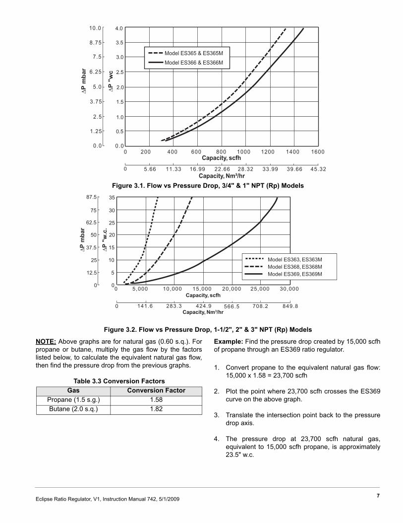
Figure 3.1. Flow vs Pressure Drop, 3/4" & 1" NPT (Rp) Models
Figure 3.2. Flow vs Pressure Drop, 1-1/2", 2" & 3" NPT (Rp) Models
NOTE: Above graphs are for natural gas (0.60 s.q.). Forpropane or butane, multiply the gas flow by the factorslisted below, to calculate the equivalent natural gas flow,then find the pressure drop from the previous graphs.
Example: Find the pressure drop created by 15,000 scfhof propane through an ES369 ratio regulator.
1. Convert propane to the equivalent natural gas flow:15,000 x 1.58 = 23,700 scfh
2. Plot the point where 23,700 scfh crosses the ES369curve on the above graph.
3. Translate the intersection point back to the pressuredrop axis.
4. The pressure drop at 23,700 scfh natural gas,equivalent to 15,000 scfh propane, is approximately23.5" w.c.
10.0
8.75
7.5
6.25
5.0
3.75
2.5
1.25
0.00 200
5.66
400
11.33
600
16.99
800
22.66
1000
28.32
1200
33.99
1400
39.66
1600
45.32
Model ES365 & ES365M
Model ES366 & ES366M
Capacity, scfh
∆P
"w
c
4.0
3.5
3.0
2.5
2.0
1.5
1.0
0.5
∆P
mba
r
0.0
Capacity, Nm³/hr0
0 5,000
141.6
10,000
283.3
15,000
424.9
20,000
566.5
25,000
708.2
30,000
849.8
Model ES363, ES363MModel ES368, ES368MModel ES369, ES369M
Capacity, scfh
∆P
"w.c
.
0
5
10
15
20
25
30
35
∆P
mba
r
0
12.5
25
37.5
50
62.5
75
87.5
0Capacity, Nm3/hr
Table 3.3 Conversion FactorsGas Conversion Factor
Propane (1.5 s.g.) 1.58Butane (2.0 s.q.) 1.82
7Eclipse Ratio Regulator, V1, Instruction Manual 742, 5/1/2009

Figure 3.3. Dimensions in inches (mm), Models ES365 (M) & ES366 (M)
Figure 3.4. Dimensions in inches (mm), Models ES363 (M), ES368 (M) & ES369 (M)
3-7/8(98.4)
1-1/2(38.1)
5-11/16(144.5)
1/8" NPTLoad Line
2-3/8(60.3)
InletES365(M) 3/4" NPT (Rp 3/4)
ES366(M) 1" NPT (Rp 1)
4(101.6)
OutletES365(M) 3/4" NPT (Rp 3/4)ES366(M) 1" NPT (Rp 1)
4-7/8(123.8)
Outlet End View
SwingRadius
EA
C
Inlet
B Dia.
D FLoad Line
Outlet End View
SwingRadius
Inlet Pressure Tap1
Inlet TestTap Connector2
1 1/4" taper pipe plug on ES363(M) and ES368(M). No tap this side on ES369(M).2 1/8" taper test tap connector, 0.34" OD (8.6 mm) for slip-on hose.
Outlet
Table 3.4Model Swing Radius Inlet/Outlet A B C D E F
ES363 6-3/16" 1-1/2" NPT 9" 7" 5-1/2" 2-3/8" 3-3/4" 1/2" NPTES363M 157.1 mm Rp 1-1/2 228.6 mm 177.8 mm 139.7 mm 60.3 mm 92.2 mm Rp 1/2ES368 9-3/16" 2" NPT 11-1/4" 9-1/8" 7-5/8" 3-1/8" 4-5/16" 3/4" NPTES368M 233.4 mm Rp 2 285.7 mm 231.7 mm 193.6 mm 79.3 mm 109.5 mm Rp 3/4ES369 13-1/4" 3" NPT 16-1/16" 13-7/16" 10-3/8" 4-7/8" 6-1/8" 3/4" NPTES369M 336.6 mm Rp 3 407.9 mm 341.3 mm 263.5 mm 123.8 mm 155.5 mm Rp 3/4
8 Eclipse Ratio Regulator, V1, Instruction Manual 742, 5/1/2009

Design & Installation 4
DesignTo select the ratio regulator best suited for a combustionsystem, several parameters need to be considered. Thefollowing steps identify those items that need to beconsidered when selecting a ratio regulator.
Ratio Regulator selection based on flow:
• Define the maximum gas flow required for thesystem.
• Identify the ratio regulator for that flow based on thecapacities listed in Table 3.2 of the “Specifications”section.
Minimum inlet pressure calculation:
• Define the pressure drop through the ratio regulatorbased on the Flow vs. Pressure Drop curves(Figures 3.1 and 3.2) and conversion factors listedin the “Specifications” section.
• Calculate the pressure losses through componentsmounted between the ratio regulator and the burner.
• Define the gas pressure required at the burner.• Calculate the minimum inlet pressure to ratio
regulator by taking 125% of the sum between theratio regulator drop, component drops and burnerpressure.
• Verify that the inlet pressure is within the ratioregulator limit. If not, make the necessary changesto the ratio regulator or the upstream pressurecontrol.
■ Shut off gas supply before installing or removingthe ratio regulator
General Installation Information• Gas flow through the ratio regulator must be in the
direction of the arrow on the body.• Make sure the gas is compatible per Table 3.1.• Ambient temperature at the valve location must
remain between 40°F and 205°F (-40°C and96.1°C).
• The ratio regulator must be mounted with the springtower in the vertical upright position.
• Allow clearance above the ratio regulator to allowaccess to the bias adjustment.
• Pipe ends are to be free of foreign material(excluding pipe dope) before connecting into theratio regulator body.
• Do not use the ratio regulator to support adjacentpiping.
Regulator/Pipe Connections1. Remove the protective caps from the ends of the ratio
regulator.
2. Apply a moderate amount of pipe dope to the malepipe threads only.
NOTE: Excessive pipe dope could contaminate the valveset thus affecting pressure regulation.
■ Regulator must be installed with spring towerpointing upward, with flow in the direction of thecast arrow on regulator body.
3. Install the ratio regulator with the flow in the directionof the flow arrow on the body.
4. When tightening the pipe into the valve body, hold theend of the regulator adjacent to that pipe.
WARNING
CAUTION
Eclipse Ratio Regulator, V1, Instruction Manual 742, 5/1/2009 9

5. Connect the air pressure loading line into the vent onthe top of the ratio regulator. The ratio regulators canbe adjusted to bias the gas outlet pressure relative tothe combustion air pressure when setting low fireflows. Adjust the regulator as described below.
Gas Bias AdjustmentNOTE: Gas-rich adjustment is limited. If the springadjustment will not produce the desired outlet pressure,make sure that the supply pressure is at least equal to thedesired outlet pressure plus the pressure drop across theregulator at the required flow.
1. Set the burner air flow to low fire according to theinstructions furnished with the burner.
2. Open the gas shut-off valves to allow gas flow to theburner. Ignite the burner.
3. Measure the fuel/air ratio using a flue gas analyzer,metering orifices or estimate the ratio from flameappearance. Use a screw driver to turn the adjustingscrew clockwise to increase the outlet pressure orcounterclockwise to decrease to outlet pressure.
4. Turn the combustion air to high fire and make sure theburners stay lit.
NOTE: Some models are equipped with a pressure tap onthe upstream side. It is open when the screw inside the tapis unscrewed approximately 1/2 a turn.
Figure 5.1. Adjustment of Outlet Pressure
10 Eclipse Ratio Regulator, V1, Instruction Manual 742, 5/1/2009

NOTES
11Eclipse Ratio Regulator, V1, Instruction Manual 742, 5/1/2009

Instruction Manual 742, 5/1/2009