Embed Size (px)
Citation preview

INSTRUCTION MANUAL H.264 NETWORK DIGITAL VIDEO SURVEILLANCE RECORDER

2
2 INSTRUCTION MANUAL
3
3 INSTRUCTION MANUAL
CONTENT
1 INTRODUCTION............................................................................................................ 4 1.1MAIN FEATURE......................................................................................................... 4 1.2 PRODUCT FEATURES ............................................................................................ 4 1.2.1 PARAMETER(4/8CH) ...................................................................................... 4 1.2.2 BASIC WORKING PARAMETER......................................................................... 5
1.3 ENVIRONMENT ADAPTABILITY.............................................................................. 6 2. DEVICE OPERATION MANUAL................................................................................... 7 2.1 REMOTE CONTROL ................................................................................................ 7 2.2 MOUSE OPERATION ............................................................................................... 8 2.2 USING THE SUB-MENU........................................................................................... 9 2.3 PLAYBACK ............................................................................................................. 10 2.4 SYSTEM OPERATION ........................................................................................... 12 2.4.1 USER LOGIN ..................................................................................................... 12 2.4.2 USING THE MAIN MENU................................................................................... 13
3. REMOTE SURVEILLANCE SOFTWARE ................................................................... 39 3.1 FEATURE ............................................................................................................... 39 3.2 USING REMOTE SURVEILLANCE ........................................................................ 40 3.3 REMOTE SURVEILLANCE MAIN SCREEN........................................................... 41 3.3.1 LIVE VIEWING ................................................................................................... 42 3.3.3 REMOTE SETUP ............................................................................................... 47
4. DVR INSTALLATION GUIDELINE.............................................................................. 52 4.1 FRONT PANEL ....................................................................................................... 52 4.2 REAR PANEL.......................................................................................................... 53 4.3 FULL CONNECTIVITY DIAGRAM .......................................................................... 55 4.4 HDD INSTALLATION .............................................................................................. 56
5. FAQ............................................................................................................................. 57
4
4 INSTRUCTION MANUAL
1 INTRODUCTION
1.1MAIN FEATURE 4/8 channels CIF/HD1/D1 resolution digital video recorder. It has local recording,
playback, support triple code remote network surveillance, data backup, parameter setting, motion detection and USB mouse.
1.2 PRODUCT FEATURES H.264 compression Two USB interface, USB2.0 for data backup, USB1.1 for mouse operation. 3.5” SATA HDD. Special file system for security. 16 bit color translucent user-friendly GUI, with notes for selected menu items Optimized four channel simultaneously playback Double level user management Support live view, parameter setting and copy playback video via network.
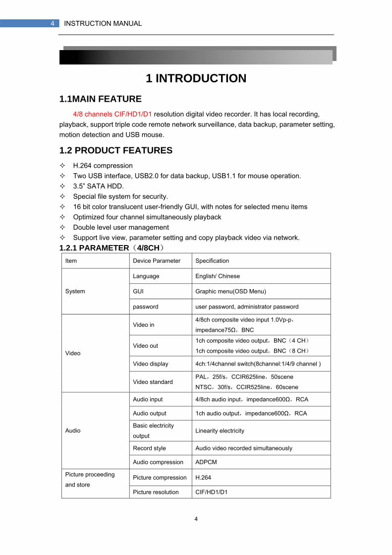
1.2.1 PARAMETER(4/8CH) Item Device Parameter Specification
Language English/ Chinese
GUI Graphic menu(OSD Menu) System
password user password, administrator password
Video in 4/8ch composite video input 1.0Vp-p,
impedance75Ω,BNC
Video out 1ch composite video output,BNC(4 CH)
1ch composite video output,BNC(8 CH)
Video display 4ch:1/4channel switch(8channel:1/4/9 channel )
Video
Video standard PAL,25f/s,CCIR625line,50scene
NTSC,30f/s,CCIR525line,60scene
Audio input 4/8ch audio input,impedance600Ω,RCA
Audio output 1ch audio output,impedance600Ω,RCA
Basic electricity
output Linearity electricity
Record style Audio video recorded simultaneously
Audio
Audio compression ADPCM
Picture compression H.264 Picture proceeding
and store Picture resolution CIF/HD1/D1

5
5 INSTRUCTION MANUAL
Streaming style ISO14496-10
Audio style ADPCM
Video code rate
(4CH)
CIF: 384~768 Kbps(normal)
HD1:512~1024Kbps(high)
D1:512~1024Kbps(highest)
Video code rate
(8CH)
CIF: 384~768 Kbps(normal)
HD1:512~1024Kbps(high)
D1:512~1024Kbps(highest)
Audio code rate 32KB/s
Data storage SATA HDD storage(optional)
Connector Network interface RJ45,10M/100M
Alarm Alarm input 4/8 alarm input
Alarm output 1 alarm output
Serial interface Support 1 RS232
Serial interface Support 1 RS485
Connector
Network interface RJ45,10M/100M
Software upgrade Support USB firmware upgrade
Voltage input AC:110~240V
Power Consumption 6W without HDD others
Working temperature -10----50
1.2.2 BASIC WORKING PARAMETER Item Parameter description
Voltage input 12V DC 12V
Voltage output for camera 12V(+/-0.2) 4channel :12V@2A (8ch W/O)
Video impedance input 75Ω 75Ω each channel
Video output 1Vp-p 1Vp-p CVBS signal
SATA HDD One SATA with mainstream capability
Working
temperature -10----50 Under normal conditions
6
6 INSTRUCTION MANUAL
1.3 ENVIRONMENT ADAPTABILITY For safety while using the DVR and to prolong device life, please pay attention to the following details:
1) When installing device, please comply with all the electric product safety criteria. 2) Power and ground:
Do not touch the power and DVR with a wet hand Do not drop liquid on DVR Do not put any object on DVR Please use soft dry cloth to clean DVR; do not use chemical impregnant. The Device will have voltage before startup if the power line is connected to power
source. Please unplug power line from power source if the Device is not intended to be used
for a prolonged time.
7
7 INSTRUCTION MANUAL
2. DEVICE OPERATION MANUAL In device operation, the enter key on remote control has the same function as left
click of the mouse.
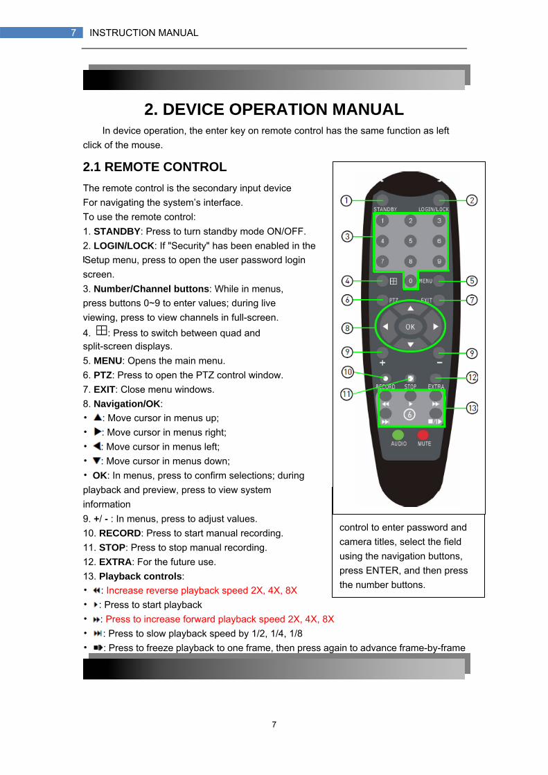
2.1 REMOTE CONTROL The remote control is the secondary input device For navigating the system’s interface. To use the remote control: 1. STANDBY: Press to turn standby mode ON/OFF. 2. LOGIN/LOCK: If "Security" has been enabled in the Setup menu, press to open the user password login screen. 3. Number/Channel buttons: While in menus, press buttons 0~9 to enter values; during live viewing, press to view channels in full-screen. 4. : Press to switch between quad and split-screen displays. 5. MENU: Opens the main menu. 6. PTZ: Press to open the PTZ control window. 7. EXIT: Close menu windows. 8. Navigation/OK: • : Move cursor in menus up; • : Move cursor in menus right; • : Move cursor in menus left; • : Move cursor in menus down; • OK: In menus, press to confirm selections; during playback and preview, press to view system information 9. +/ - : In menus, press to adjust values. 10. RECORD: Press to start manual recording. 11. STOP: Press to stop manual recording. 12. EXTRA: For the future use. 13. Playback controls: • : Increase reverse playback speed 2X, 4X, 8X • : Press to start playback • : Press to increase forward playback speed 2X, 4X, 8X • : Press to slow playback speed by 1/2, 1/4, 1/8 • : Press to freeze playback to one frame, then press again to advance frame-by-frame
TIP: When using the remote control to enter password and camera titles, select the field using the navigation buttons, press ENTER, and then press the number buttons.

8
8 INSTRUCTION MANUAL
2.2 MOUSE OPERATION The mouse is the primary input device for navigating system menus. NOTE: Unless otherwise noted, all system functions described in this manual are achieved through mouse input. To use a mouse with the system:
1) Connect a USB mouse to the USB MOUSE port on front panel of the system. NOTE: Only the top USB port on the front panel is designed for data backup to a USB
flash drive. Do not connect a USB flash drive to the bottom USB port on the rear panel.
Figure 1.0 Connect a USB mouse to the bottom USB port on the front panel
2) Use the mouse buttons to perform the following: • Left-Button: Click to select a menu option; during live viewing in split-screen, double-click on a channel to view the selected channel in full-screen.; double-click the channel again to return to split-screen view • Right-Button: Click to open the Sub-Menu
3) Scroll-Wheel: forward-switch to VGA;backward-switch to CVBS Figure 1.1 Mouse button operation

9
9 INSTRUCTION MANUAL
2.2 USING THE SUB-MENU Mouse Only
When using the mouse, use the Sub-Menu to access several system options, including the Main Menu and PTZ control. To open the Sub-Menu:
1) Right-click anywhere onscreen. The Sub-Menu opens.
2) Select one of the following options:
• MAIN MENU: Opens the main system menu • KEYLOCK: Locks buttons on the front panel • CHN SWITCH: Select type of split-screen display • VIDEO SEARCH: Open the Search Menu to view recorded video • PTZ: Opens the PTZ control menu • MUTE: Mute listen-in audio on the system • MANUAL REC: Start manual recording • STOP REC: Stop manual recording • ROTATION: Video rotation Standby:Click and go into standby status
3) To close the Sub-Menu, click anywhere onscreen.

10
10 INSTRUCTION MANUAL
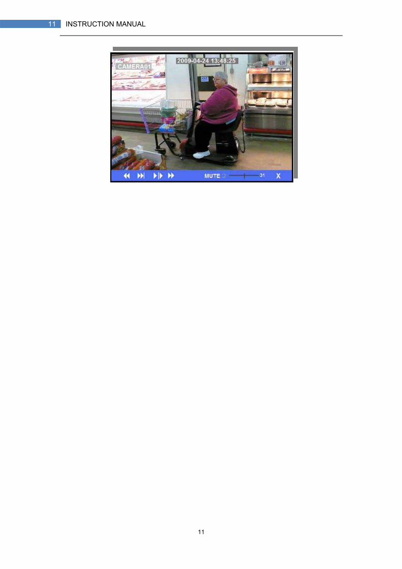
2.3 PLAYBACK View recorded video on the system through the Search Menu. To begin playback:
1) Right-click anywhere onscreen and select VIDEO
SEARCH. The Search Menu opens.
NOTE: When you first open the Search Menu, it displays the current month and date.
2) Click PLAY to playback the last minute of recorded video (Quick Search). OR
3) Under CHN select a specific channel or select ALL. 4) Under DATE, enter a date using the Virtual Keyboard (mouse only). 5) Click SEARCH. Recorded events on the system
appear in red (alarm events—includes both alarm and motion events) and green (normal recording).
6) Click a date in the Month Grid to search for video files. 7) Click a time block in the Hour Grid to view the video. Playback begins.
ATTENTION: Only single channel full-screen playback is available on 8-channel models; 4-channel models have full-screen and quad-screen playback.
8) Move the mouse slightly to display the onscreen playback controls. You can also use the playback control buttons on the remote control or front panel of the system.
Onscreen Playback Controls To use the onscreen playback controls:
1) Click the VCR-like controls to play, pause, fast forward, rewind, and slow down playback.
2) Drag the slider to adjust the volume (audio capable camera required, not included). Select the box to mute the audio.
3) Click X to quit playback and return to the Search menu.
11
11 INSTRUCTION MANUAL

12
12 INSTRUCTION MANUAL
2.4 SYSTEM OPERATION 2.4.1 USER LOGIN 1. STARTING THE SYSTEM To power the system ON/OFF:
Connect the power cable to the DC 19V port on the rear panel. At startup, the system performs a basic system check and runs an initial loading sequence. After a few moments, the system loads a live display view. Standby Mode
The system can also be put into Standby Mode. Power will remain to the system but will not be recording. To start/stop Standby mode:
1) Press and hold the POWER button on the front panel or remote control until the prompt closes. The system enters standby mode.
2) Press and hold the POWER button on the front panel or remote control until the system beeps. The system will begin powering up.
Password ATTENTION: By default, passwords are disabled on the system. You do not need to
enter a password when accessing any system menus. However, for security purposes, it is highly recommended to enable passwords on the system using the Password Menu. NOTE:
1) If there is no HDD in device, or the device didn`t read the HDD, or the HDD didn`t be formatted it will display an 【H】 in the video preview interface.
2) You must format the HDD in the DVR before first using. The steps as follows: menu > HDD management > format. After formatting, the system will restart.
2. SYSTEM LOGIN To open the Main Menu:
Right-click anywhere onscreen to open the Sub-Menu and select MAIN MENU (mouse only), or press the MENU/EXIT button on the remote control or front panel of the system.
NOTE: If passwords are enabled on the system, you need to select your Device ID and enter the 6-digit numerical password to open the Main Menu.
Figure 2.4.1 user login menu
13
13 INSTRUCTION MANUAL
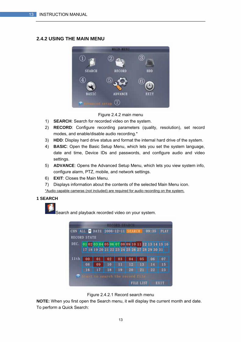
2.4.2 USING THE MAIN MENU
Figure 2.4.2 main menu
1) SEARCH: Search for recorded video on the system. 2) RECORD: Configure recording parameters (quality, resolution), set record
modes, and enable/disable audio recording.* 3) HDD: Display hard drive status and format the internal hard drive of the system. 4) BASIC: Open the Basic Setup Menu, which lets you set the system language,
date and time, Device IDs and passwords, and configure audio and video settings.
5) ADVANCE: Opens the Advanced Setup Menu, which lets you view system info, configure alarm, PTZ, mobile, and network settings.
6) EXIT: Closes the Main Menu. 7) Displays information about the contents of the selected Main Menu icon. *Audio capable cameras (not included) are required for audio recording on the system.
1 SEARCH
Search and playback recorded video on your system.
Figure 2.4.2.1 Record search menu
NOTE: When you first open the Search menu, it will display the current month and date. To perform a Quick Search:
14
14 INSTRUCTION MANUAL
Open the Search menu and click PLAY. The last minute of recorded playback begins. To perform a Date & Time search:
1) Under CHN, select individual channels or select ALL. 2) Under DATE, click the field and enter the desired date using the Virtual Keyboard
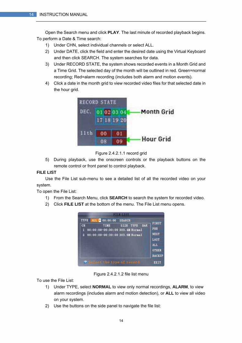
and then click SEARCH. The system searches for data. 3) Under RECORD STATE, the system shows recorded events in a Month Grid and
a Time Grid. The selected day of the month will be outlined in red. Green=normal recording; Red=alarm recording (includes both alarm and motion events).
4) Click a date in the month grid to view recorded video files for that selected date in the hour grid.
Figure 2.4.2.1.1 record grid 5) During playback, use the onscreen controls or the playback buttons on the
remote control or front panel to control playback. FILE LIST
Use the File List sub-menu to see a detailed list of all the recorded video on your system. To open the File List:
1) From the Search Menu, click SEARCH to search the system for recorded video. 2) Click FILE LIST at the bottom of the menu. The File List menu opens.
Figure 2.4.2.1.2 file list menu
To use the File List: 1) Under TYPE, select NORMAL to view only normal recordings, ALARM, to view
alarm recordings (includes alarm and motion detection), or ALL to view all video on your system.
2) Use the buttons on the side panel to navigate the file list:
15
15 INSTRUCTION MANUAL
• FIRST: Jump to the first page of the list • PRE: Turn to the previous page • NEXT: Turn to the next page • LAST: Jump to the last page of the list • ALL: Select all files • OTHER: Clear all files • BACKUP: After selecting a file(s), click to begin copying the data to a USB
flash drive (not included); 3) Click any file to begin playback.
2 BACKUP
Use the File List sub-menu to find recorded video on your system and copy it to a USB flash drive (not included).
NOTE: The system is compatible with most major brands of USB flash drives, with capacities from
256 MB to 4 GB.
To backup recorded data: 1) Connect a blank USB flash drive to the top USB port on the front panel of the
system. 2) Open the Search menu and search for recorded data on the system. 3) Click FILE LIST. 4) Select the files you want to backup and click the "BAK" box next to the file
name (see figure 0.0). Select multiple files if desired. Click ALL to select all files; click OTHER to deselect all files.
NOTE: The size of each file is shown in the File List menu. Use this to help you find a USB flash drive large enough to hold all the files you wish to backup.
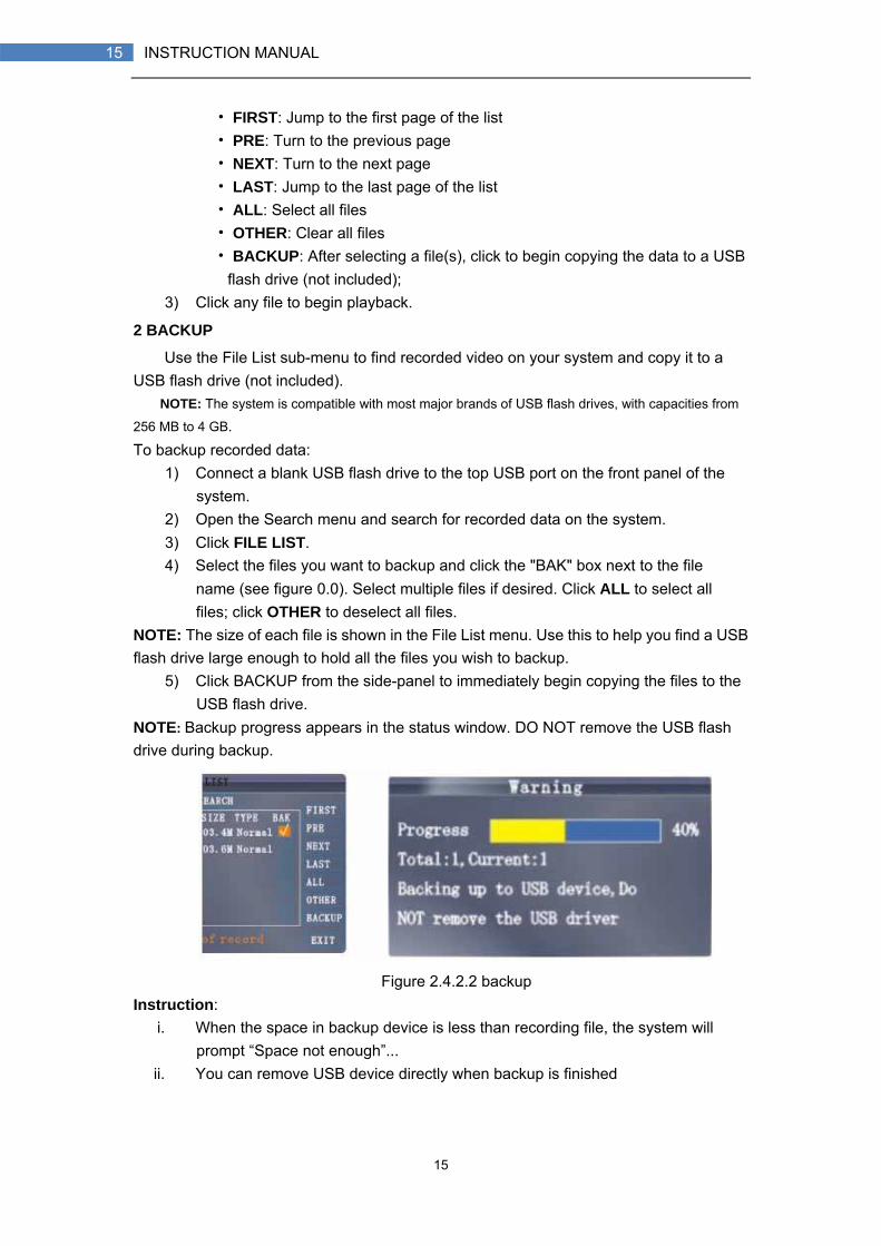
5) Click BACKUP from the side-panel to immediately begin copying the files to the USB flash drive.
NOTE: Backup progress appears in the status window. DO NOT remove the USB flash drive during backup.
Figure 2.4.2.2 backup
Instruction: i. When the space in backup device is less than recording file, the system will
prompt “Space not enough”... ii. You can remove USB device directly when backup is finished
16
16 INSTRUCTION MANUAL
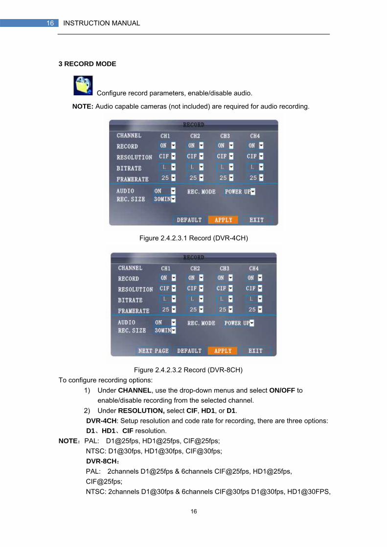
3 RECORD MODE
Configure record parameters, enable/disable audio.
NOTE: Audio capable cameras (not included) are required for audio recording.
Figure 2.4.2.3.1 Record (DVR-4CH)
Figure 2.4.2.3.2 Record (DVR-8CH) To configure recording options:
1) Under CHANNEL, use the drop-down menus and select ON/OFF to enable/disable recording from the selected channel.
2) Under RESOLUTION, select CIF, HD1, or D1. DVR-4CH: Setup resolution and code rate for recording, there are three options: D1、HD1、CIF resolution.
NOTE:PAL: D1@25fps, HD1@25fps, CIF@25fps; NTSC: D1@30fps, HD1@30fps, CIF@30fps;
DVR-8CH: PAL: 2channels D1@25fps & 6channels CIF@25fps, HD1@25fps, CIF@25fps;
NTSC: 2channels D1@30fps & 6channels CIF@30fps D1@30fps, HD1@30FPS,

17
17 INSTRUCTION MANUAL
CIF@30fps; 3) Under Bitrate. Select L, M, or H, Setup bitrate for recording,corresponding to 384Kbps、512Kbps and 768Kbps. 4) Under AUDIO, select ON or OFF. If audio recording is ON, the system will
record audio from connected audio capable cameras (not included). 5) Under REC. MODE, select POWER UP or TIMER RECORD. If you select
POWER UP, the system will record continuously (Normal Recording) when the system is powered on. If you select TIMER RECORD, you have to set a recording schedule on the system.
6) Under REC. SIZE, select 15MIN, 30MIN, 45MIN, or 60MIN. NOTE: Record Size sets the file size for recorded video files on the system. Instead of recording data as one large file, the system will divide the data into blocks of 15, 30, 45, or 60 minutes. This makes the recorded data easier to search.
7) Click APPLY. Click CLOSE in the confirmation window. 8) Click EXIT in every menu until all windows are closed.
Recording Schedule By default, the system is set to record continuously. You can program the system to
record according to a customized recording schedule.
Figure 2.4.2.3.1 Recording Schedule The Schedule Grid shows the days of the week and hours 0~23. You can set Alarm
Recording (Red), General (Normal) Recording (Green), or No Recording (Blue) to each time block of each day. To set a recording schedule:
1) Open the Main Menu and click RECORD. 2) Under REC. MODE, select TIMER RECORD. 3) Click SCHEDULE. The Schedule menu opens. 4) Under CHANNEL, select specific channels or select ALL. 5) Below the grid, click either ALARM (red), GENERAL (Green), or NO RECORD
(Blue) and then click a time block on the desired day. 6) Use the FROM/TO drop-down menus to copy the schedule of one day to another.

18
18 INSTRUCTION MANUAL
For example, if you want your schedule for Monday to be the same on Wednesday: under FROM select MON, under TO select WED, and then click COPY.
7) Click SAVE. 8) Click EXIT in each menu until all windows are closed.
Example You want your system to record continuously on all channels from 9 AM to 5 PM
Monday to Friday. You also want Alarm/Motion recording from 5 PM to 9 AM. You do not want the system to record Saturday or Sunday. NOTE: By default, the system is set to record continuously 24 hours a day, 7 days a week. To set the recording schedule:
1) Open the Schedule menu. 2) Under CHANNEL, select ALL. 3) Click the blue NO RECORD block below the grid. A checkmark will appear in the
block. 4) Under SUN, click blocks 00~23. The blocks will turn blue. 5) Under FROM, select SUN. Under TO select SAT, and then click COPY. 6) Click the red ALARM block below the grid. 7) Under MON, click blocks 00~08 and blocks 18~23. The blocks will turn red. 8) Under FROM, select MON. Under TO select TUE, and then click COPY. Repeat
for Wednesday, Thursday, and Friday. Your completed schedule should the same as the schedule in Figure 2.4.2.3.2.
Figure 2.4.2.3.2 Customized recording schedule
9) Click SAVE. Click CLOSE in the confirmation window. 10) Click EXIT in all menus until all windows are closed.
Mask Field Setup——————————(To be completed soon) The Mask Field lets you block a specific portion of a channel you do not want
recorded or shown on the display screen. This can be useful if you need to conceal a sensitive area being captured by the installed camera.

19
19 INSTRUCTION MANUAL
Figure 2.4.2.3.3 Mask Field Menu To use the mask field:
1) From the Record menu, click MASK FIELD SETUP. The Mask Field menu opens.
2) Choose a channel you wish to apply the Mask Field. Click NEXT PAGE if necessary (8-channel models only). Select ON from the SWITCH drop-down menu.
3) Click SETUP. The Mask Menu disappears and the select channel is shown in full-screen.
4) Using the mouse, click and drag the cursor over the area you want to conceal. A single click will produce a small black square.
Figure 2.4.2.3.4 Mask Field
5) Right-click anywhere on the screen to return to the Mask Field menu. 6) Click APPLY. Click CLOSE in the confirmation window. 7) Click EXIT in all menus until all windows are closed.
4 HDD MANAGEMENT
Displays essential information about the system`s internal hard drive, and lets you format the internal HDD and external USB flash drive (not included).

20
20 INSTRUCTION MANUAL
Figure 2.4.2.4 HDD management menu
The HDD menu displays the following: • HDD STATUS: The system will display "OK" for normal operation • SIZE: The size (in gigabytes) of the internal hard disk drive. The size of your
system`s internal hard drive will vary by model • FREE SPACE: The space (in gigabytes) remaining on the system`s internal HDD • AVAILABLE TIME: The recording time (in hours) remaining on the HDD based on
your current record settings • OVERWRITE: Select ENABLE or DISABLE. If Overwrite is enabled, the system
will record over the oldest video data once the HDD is full. If Overwrite is disabled, the system will stop recording once the HDD is full and the "FULL" LED on the front panel of the system will light up.
Formatting the Hard Drive ATTENTION: Formatting the HDD will erases all video data. This step cannot be Undone. Formatting the USB Flash Drive
Use a USB flash drive to backup recorded video and upgrade the system`s firmware. You should always format the USB flash drive you intend to use with the system. NOTE: Not formatting the USB flash drive may result in improper functionality.
5 BASIC
Set the system language, date and time, passwords, and configure audio and display options.
The Basic Setup menu contains the following sub-menus: Language, Date/Time, Password, Display, and Video/Audio.

21
21 INSTRUCTION MANUAL
Figure 2.4.2.5 Basic Setup menu
22
22 INSTRUCTION MANUAL
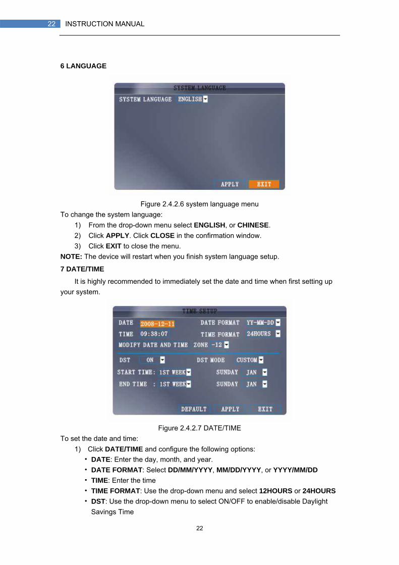
6 LANGUAGE
Figure 2.4.2.6 system language menu
To change the system language: 1) From the drop-down menu select ENGLISH, or CHINESE. 2) Click APPLY. Click CLOSE in the confirmation window. 3) Click EXIT to close the menu.
NOTE: The device will restart when you finish system language setup.
7 DATE/TIME
It is highly recommended to immediately set the date and time when first setting up your system.
Figure 2.4.2.7 DATE/TIME
To set the date and time: 1) Click DATE/TIME and configure the following options:
• DATE: Enter the day, month, and year. • DATE FORMAT: Select DD/MM/YYYY, MM/DD/YYYY, or YYYY/MM/DD • TIME: Enter the time • TIME FORMAT: Use the drop-down menu and select 12HOURS or 24HOURS • DST: Use the drop-down menu to select ON/OFF to enable/disable Daylight
Savings Time

23
23 INSTRUCTION MANUAL
2) Click MODIFY DATE AND TIME. Click CLOSE in the confirmation window. 3) Click APPLY. The new date and time are saved.
Daylight Savings Time To set daylight savings time:
1) Under DST, select ON. DST options appear. 2) Under DST MODE select one of the following:
• CUSTOM: Set customized start and end times for DST (go to step 4) • DEFAULT: The Default setting will apply DST from the second Sunday of March to the second Sunday in November (go to step 3)
3) If using the DEFAULT, click APPLY. 4) If setting a CUSTOM DST, use the drop-down menus to select a week and
month for the start and end times. 5) Click APPLY. Click CLOSE in the confirmation window. 6) Click EXIT in each menu until all windows are closed.tem date via numeric key.
8 PASSWORD
一, USER SETUP
Click User setup and enter into setting interface
1) Device ID: DVR ID 2) USER NAME:USER NAME, can be changed 3) LEVEL: User level, All users can be divided into two levels. One is ADMINTRATOR,
The other NORMAL user 4) STATE:User state. ACTIVE/INACTIVE 5) CONFIG:CONFIG user
NOTE: Only administrator and the user with super password can do all operation. Normal
24
24 INSTRUCTION MANUAL
User just can parts of them, and can not do CONFIG
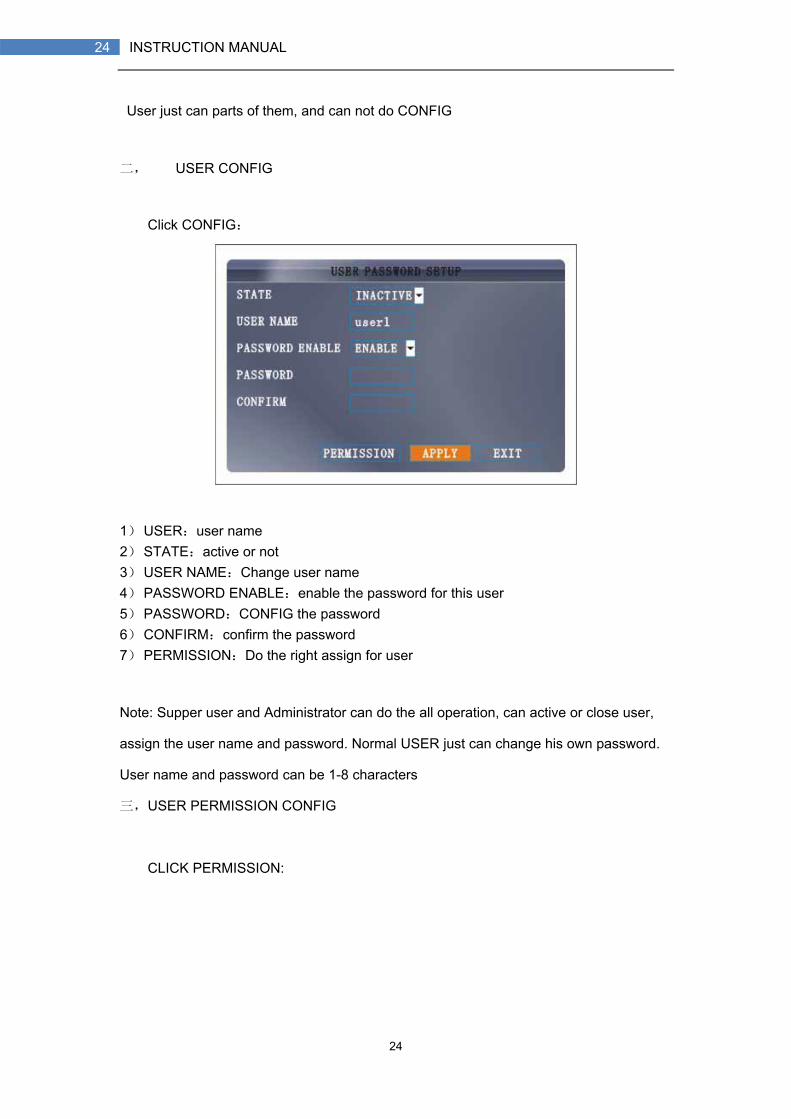
二, USER CONFIG
Click CONFIG:
1) USER:user name 2) STATE:active or not 3) USER NAME:Change user name 4) PASSWORD ENABLE:enable the password for this user 5) PASSWORD:CONFIG the password 6) CONFIRM:confirm the password 7) PERMISSION:Do the right assign for user
Note: Supper user and Administrator can do the all operation, can active or close user,
assign the user name and password. Normal USER just can change his own password.
User name and password can be 1-8 characters
三,USER PERMISSION CONFIG
CLICK PERMISSION:

25
25 INSTRUCTION MANUAL
1) Select different permissions 2) NEXT:come to next selecting page 3) ALL:select all permissions 4) CLEAN:Clean all permissions
Note: This page is working for administrator. Administrator can assign permissions for
user. User just can see but can not change their permissions。
Currently, we have following permissions:
一、1-16ch(channel number depends DVR model. E.G, 8 channel DVR have 8ch setting)
IE preview function. User just can see the assigned channels.
二、1-16ch(channel number depends DVR model. E.G, 8 channel DVR have 8ch setting)
video playback. User just can playback the assigned channel. Otherwise, can not do any
operation
三、video parameter CONFIG, HDD management, Language setting, time setting, display,
audio, system info, MD, Mobile phone, system maintain, PTZ, network setting. Beside,
Standby also need assign.
Multi-Client Login

26
26 INSTRUCTION MANUAL
Select active USER.(Can not key in USER NAME. Device will select the active user and
show here for choice),then key in the device ID and user password
9 DISPLAY
DISPLAY Use the Display Setup menu to customize channel titles, show/hide the date and time
in live viewing and playback, and enable/disable preview channels.
Figure 2.4.2.9 display
To customize Display settings: 1) Configure the following options:
• NAME: Click any of the fields and enter a new title for the selected channel using the Virtual Keyboard (mouse only)
• POSITION: Reposition the channel title; select TOPLEFT, BOTTOMLEFT, TOPRIGHT, BOTTOMRIGHT, or OFF. If OFF, the title will not be displayed for the selected channel
• COLOR: Adjust CHROMATICITY, LUMINOSITY, CONTRAST, and SATURATION for the selected channel
• PREVIEW TIME: Select ON/OFF to show/ hide the date and time during live viewing
• RECORD TIME: Select ON/OFF to show/hide the date and time during
27
27 INSTRUCTION MANUAL
playback. 2) Click NEXT PAGE to change the settings for the remaining channels (8-channel
models only). 3) Click APPLY to save your settings. Click CLOSE in the confirmation window.
Preview Preview channels can be very useful if your display monitor is in public view. Select
OFF of a preview channel will appear black on the display to give the impression that no cameras are connected and the system is not recording. To enable/disable preview channels:
1) Choose a channel you wish to conceal. For example, channel 3. Under PREVIEW, select OFF.
2) Click APPLY. Channel 3 will turn black. Click CLOSE in the confirmation window. 3) Click EXIT in all menus until al windows are closed.
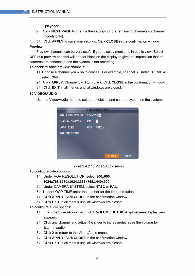
10 VIDEO/AUDIO
Use the Video/Audio menu to set the resolution and camera system on the system.
Figure 2.4.2.10 Video/Audio menu
To configure video options: 1) Under VGA RESOLUTION, select 800x600,
1024x768,1280x1024,1366x768,1440x900. 2) Under CAMERA SYSTEM, select NTSC or PAL. 3) Under LOOP TIME,enter the number for the time of rotation. 4) Click APPLY. Click CLOSE in the confirmation window. 5) Click EXIT in all menus until all windows are closed.
To configure audio options: 1) From the Video/Audio menu, click VOLUME SETUP. A split-screen display view
appears. 2) Click any channel and adjust the slider to increase/decrease the volume for
listen-in audio. 3) Click X to return to the Video/Audio menu. 4) Click APPLY. Click CLOSE in the confirmation window. 5) Click EXIT in all menus until all windows are closed.

28
28 INSTRUCTION MANUAL
11 ADVANCE
Use the Advanced Setup menu to configure alarm settings, motion detection, mobile surveillance, PTZ settings and network settings. The Advanced Setup menu contains the following sub-menus: Alarm, Info, MD, Mobile, System, PTZ, and Network.
Figure 2.4.2.11 Video/Audio menu
12 ALARM
Use the Alarm menu to configure alarm and email settings. NOTE: External alarm devices must be connected to the alarm block on the rear panel of the system in order to use the I/O (input/ output) alarms of the system.
Figure 2.4.2.12.1 Alarm setup menu
To configure alarm settings: 1) Under I/O CHANNEL, select NO (Normal Open), NC (Normal Closed), or OFF. Click NEXT PAGE to view additional channels (8-channel models only). 2) Apply loss alarms to the following:
• HDD LOSS: The alarm will sound if the internal HDD is damaged • HDD SPACE: The alarm will sound when the HDD is full (overwrite must be
29
29 INSTRUCTION MANUAL
disabled) • VIDEO LOSS: The alarm will sound when a camera is disconnected
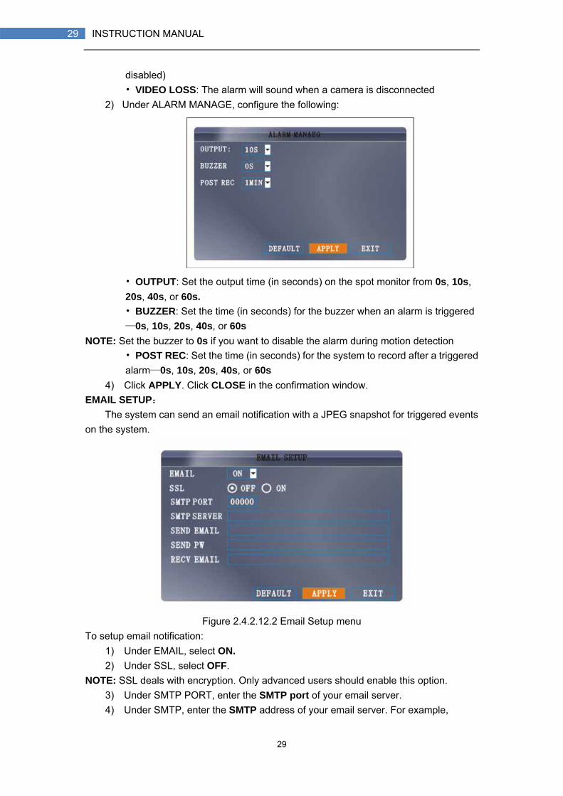
2) Under ALARM MANAGE, configure the following:
• OUTPUT: Set the output time (in seconds) on the spot monitor from 0s, 10s, 20s, 40s, or 60s. • BUZZER: Set the time (in seconds) for the buzzer when an alarm is triggered—0s, 10s, 20s, 40s, or 60s
NOTE: Set the buzzer to 0s if you want to disable the alarm during motion detection • POST REC: Set the time (in seconds) for the system to record after a triggered alarm—0s, 10s, 20s, 40s, or 60s
4) Click APPLY. Click CLOSE in the confirmation window. EMAIL SETUP:
The system can send an email notification with a JPEG snapshot for triggered events on the system.
Figure 2.4.2.12.2 Email Setup menu
To setup email notification: 1) Under EMAIL, select ON. 2) Under SSL, select OFF.
NOTE: SSL deals with encryption. Only advanced users should enable this option. 3) Under SMTP PORT, enter the SMTP port of your email server. 4) Under SMTP, enter the SMTP address of your email server. For example,

30
30 INSTRUCTION MANUAL
smtp.gmail.com 5) Under SEND EMAIL, enter the sender email address. 6) Under SEND PW, enter the password of your email server. 7) Under RECV EMAIL, enter the email address that will receive the email
notification. 8) Click APPLY. Click CLOSE in the confirmation window. 9) Click EXIT in all menus until all windows are closed.
31
31 INSTRUCTION MANUAL
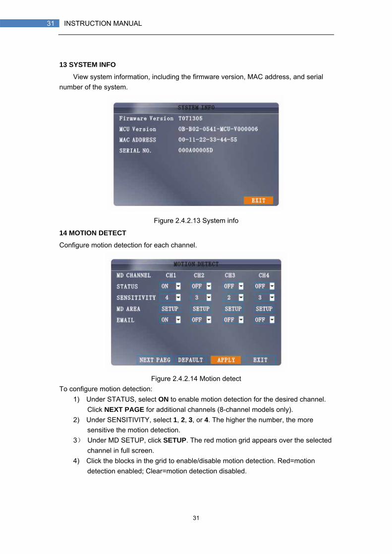
13 SYSTEM INFO
View system information, including the firmware version, MAC address, and serial number of the system.
Figure 2.4.2.13 System info
14 MOTION DETECT
Configure motion detection for each channel.
Figure 2.4.2.14 Motion detect
To configure motion detection: 1) Under STATUS, select ON to enable motion detection for the desired channel.
Click NEXT PAGE for additional channels (8-channel models only). 2) Under SENSITIVITY, select 1, 2, 3, or 4. The higher the number, the more
sensitive the motion detection. 3) Under MD SETUP, click SETUP. The red motion grid appears over the selected
channel in full screen. 4) Click the blocks in the grid to enable/disable motion detection. Red=motion
detection enabled; Clear=motion detection disabled.
32
32 INSTRUCTION MANUAL
5) Right-click anywhere on the screen to return to the Motion Detection menu. 6) Click APPLY. Click CLOSE in the confirmation window. 7) Click EXIT in all menus until all windows are closed.
NOTE: You can disable the MD buzzer in the Alarm Setup menu.
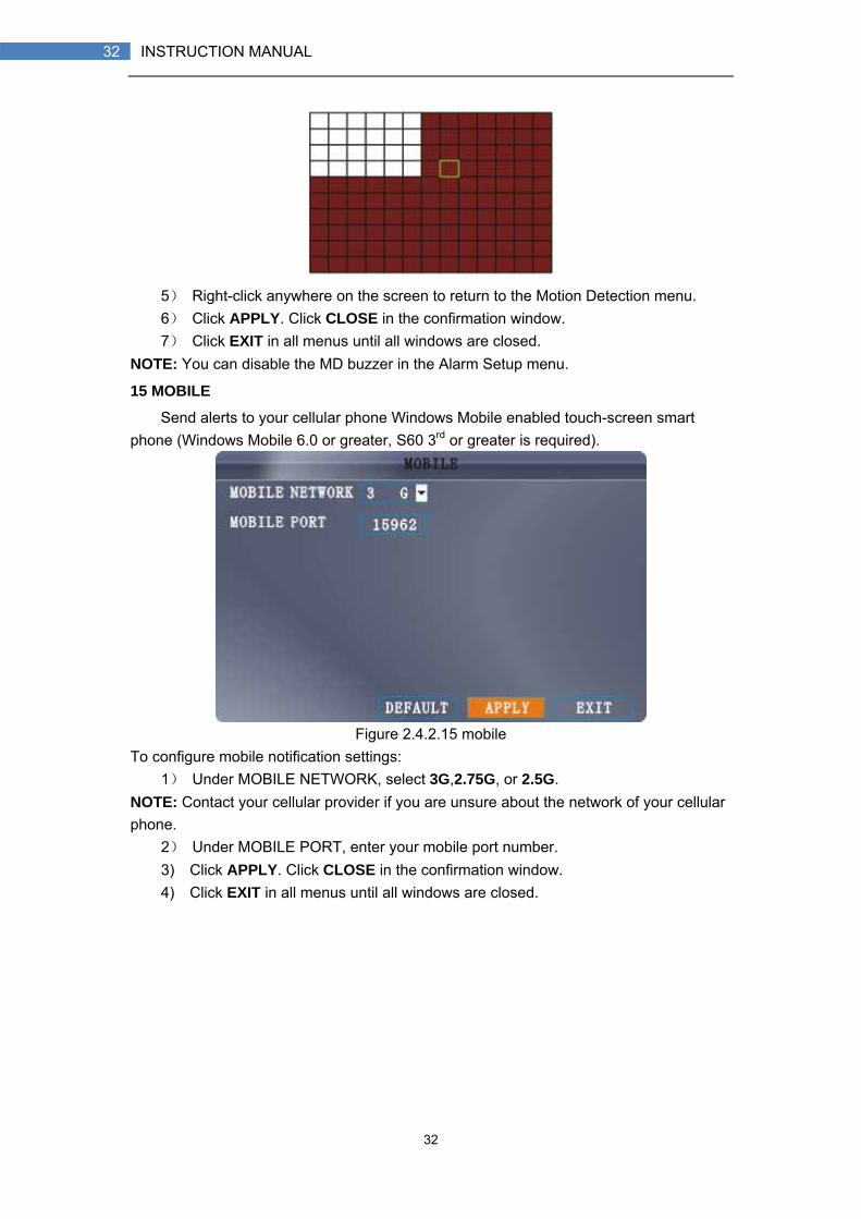
15 MOBILE
Send alerts to your cellular phone Windows Mobile enabled touch-screen smart phone (Windows Mobile 6.0 or greater, S60 3rd or greater is required).
Figure 2.4.2.15 mobile
To configure mobile notification settings: 1) Under MOBILE NETWORK, select 3G,2.75G, or 2.5G.
NOTE: Contact your cellular provider if you are unsure about the network of your cellular phone.
2) Under MOBILE PORT, enter your mobile port number. 3) Click APPLY. Click CLOSE in the confirmation window. 4) Click EXIT in all menus until all windows are closed.

33
33 INSTRUCTION MANUAL
16 SYSTEM
Use the System menu to update system firmware and set an automatic system reset schedule.
Figure 2.4.2.16 system To enable auto-reset:
1) Under AUTO RESET, select ON. The Settings option appears. 2) Under SETTINGS, select EVERY DAY, EVERY WEEK, or EVERY MONTH. The
date drop-down menu appears. 3) Select the date for auto-reset from the drop-down menu. 4) Enter the time for auto-reset using the Virtual Keyboard (mouse only). 5) Click APPLY. Click CLOSE in the confirmation window
To restore factory settings: 1) Click DEFAULT SETTINGS. This will restore the system to the original factory
settings. 2) Click OK in the prompt.
NOTE: Recorded video on the HDD will not be erased. To restart the machine (soft-reset):
1) Click RESTART. 2) Click OK in the prompt. The system will perform a soft-reset and load to a live
split-screen view. To upgrade firmware:
1) Copy the firmware file to an empty USB flash drive. The firmware file should not be in a folder.
2) Connect the USB flash drive to the top USB port on the front panel of your system.
3) Open the System Menu (Main Menu>Advance>System). 4) Click FIRMWARE UPDATE. The system will scan the USB flash drive and begin
updating the firmware. Do not remove the USB flash drive while the upgrade is taking place.

34
34 INSTRUCTION MANUAL
5) The system will restart for updating.
PARAMETER EXPORT:Copy the system settings of the device to an empty USB flash drive. PARAMETER IMPORT:Import system settings from another device.
17 PTZ
Use the PTZ Setup menu to configure settings for a connected PTZ camera (not included). NOTE: Consult the instruction manual of your PTZ camera for complete information about your camera, including protocol and baud rate.
Figure 2.4.2.17 PTZ setup
To configure a PTZ camera: 1) Connect a PTZ camera to the BNC and 485A (TX, +) and 485B (RX, -) ports and
power outlet. For more details on connecting a PTZ camera. 2) Under PROTOCOL, select PELCO-D or PELCO-P for the selected channel.
Click NEXT PAGE for additional channels (8-channel models only). 3) Under BAUD RATE, select 1200, 2400, 4800, or 9600. 4) Under DATA BIT select 5, 6, 7, or 8. 5) Under STOP BIT, select 1 or 2. 6) Under VERIFY, select ODD, EVEN, MARK, SPACE, or NONE. 7) Under ADDRESS, enter an address from 001~255 using the Virtual Keyboard.

35
35 INSTRUCTION MANUAL
Refer to your PTZ camera`s instruction manual for further details. 8) Click APPLY. Click CLOSE in the confirmation window. 9) Click EXIT in all menus until all windows are closed.

36
36 INSTRUCTION MANUAL
18 NETWORK
Use the Network Setup menu to configure your network and DNS settings.
Figure 2.4.2.18.1 network setup
UPNP UPnP Forum is an industry initiative designed to enable simple and robust connectivity among consumer electronics, intelligent appliances and mobile devices from many different vendors. As a group, we are dedicated to making the connected home and lifestyle mainstream experiences for consumers - and great opportunities for the industry. NOTE: Need your Router to support UPNP function. To configure UPNP settings:
1) Enable the UPNP function in your Router. 2) Under DVR GUI,Open the MAIN MENU and click ADVANCE. 3) From the Advanced Setup menu, click NETWORK. 4) Under UPNP, select OPEN. 5) Click APPLY to save your settings and then click OK in the confirmation window. 6) Using a remote PC, open Internet Explorer. 7) In the address bar, enter your Router WAN IP address immediately followed
by :WEB PORT (no spaces). http://XXX.XXX.XXX.XXX(Router WAN IP):XXX(WEB PORT) 8) Enter your system ADMIN password and select INTERNET.
NOTE: If you have not enabled passwords on the system, leave the password field blank. 9) Click LOGIN.
To configure network settings: 1) Under TYPE, select DHCP, PPPoE, or STATIC. If DHCP, go to step 5. If PPPoE,
go to step 2. If STATIC, go to step 3. NOTE: DHCP allows you to quickly connect to your network by obtaining an IP
address from the router. After the initial setup, we recommend that you disable DHCP and set the IP address between 1~100. For example, if your IP address is 192.168.0.107, change the last digits to 90 (i.e. 192.163.0.90). This ensures that port forwarding will not change in the event of power failure or resetting of your network.
2) If you select PPPoE in step 1, enter your PPPoE user name and password in the respective fields using the Virtual Keyboard.

37
37 INSTRUCTION MANUAL
Figure 2.4.2.18.2 PPPoE
3) If you selected STATIC in step 1, enter your IP Address, Net mask, and Gateway in the respective fields using the Virtual Keyboard.
NOTE: The default IP address of the system is 192.168.3.97 4) If necessary, change the Media and Web Ports.
NOTE: For added security, we strongly recommend changing Web port 80 on the system to any desired port not blocked by your Internet service provider (ISP). Please note however, that you will also need to update the Web port in your browser and open this new port in your router.
5) Click APPLY. Click CLOSE in the confirmation window. 6) Click EXIT in all menus until all windows are closed. The system restarts
automatically. Manual DNS Enter the Primary or Secondary DNS from your router. This is required for DDNS to function properly. To obtain your Primary or Secondary DNS:
1) In your web browser, log in to your router using its Default Gateway address. NOTE: Refer to your router`s manual or software for login information. You can also get the Default Gateway on your PC by selecting Start>Run. Type CMD and press Enter. In the Command Prompt window type ipconfig and press Enter.
2) View its WAN settings. Enter the Primary or Secondary DNS address in the MANUAL DNS field on your system.
38
38 INSTRUCTION MANUAL
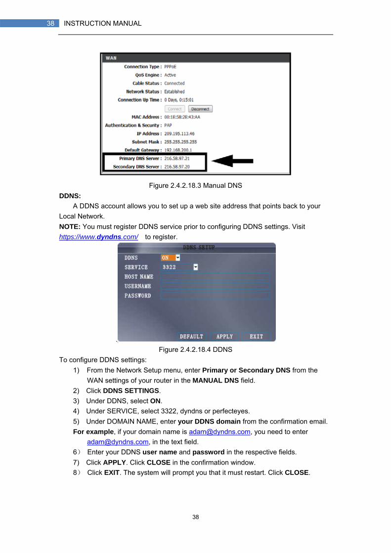
Figure 2.4.2.18.3 Manual DNS DDNS:
A DDNS account allows you to set up a web site address that points back to your Local Network. NOTE: You must register DDNS service prior to configuring DDNS settings. Visit https://www.dyndns.com/ to register.
. Figure 2.4.2.18.4 DDNS
To configure DDNS settings: 1) From the Network Setup menu, enter Primary or Secondary DNS from the
WAN settings of your router in the MANUAL DNS field. 2) Click DDNS SETTINGS. 3) Under DDNS, select ON. 4) Under SERVICE, select 3322, dyndns or perfecteyes. 5) Under DOMAIN NAME, enter your DDNS domain from the confirmation email. For example, if your domain name is [email protected], you need to enter
[email protected], in the text field. 6) Enter your DDNS user name and password in the respective fields. 7) Click APPLY. Click CLOSE in the confirmation window. 8) Click EXIT. The system will prompt you that it must restart. Click CLOSE.
39
39 INSTRUCTION MANUAL
3. REMOTE SURVEILLANCE SOFTWARE 3.1 FEATURE
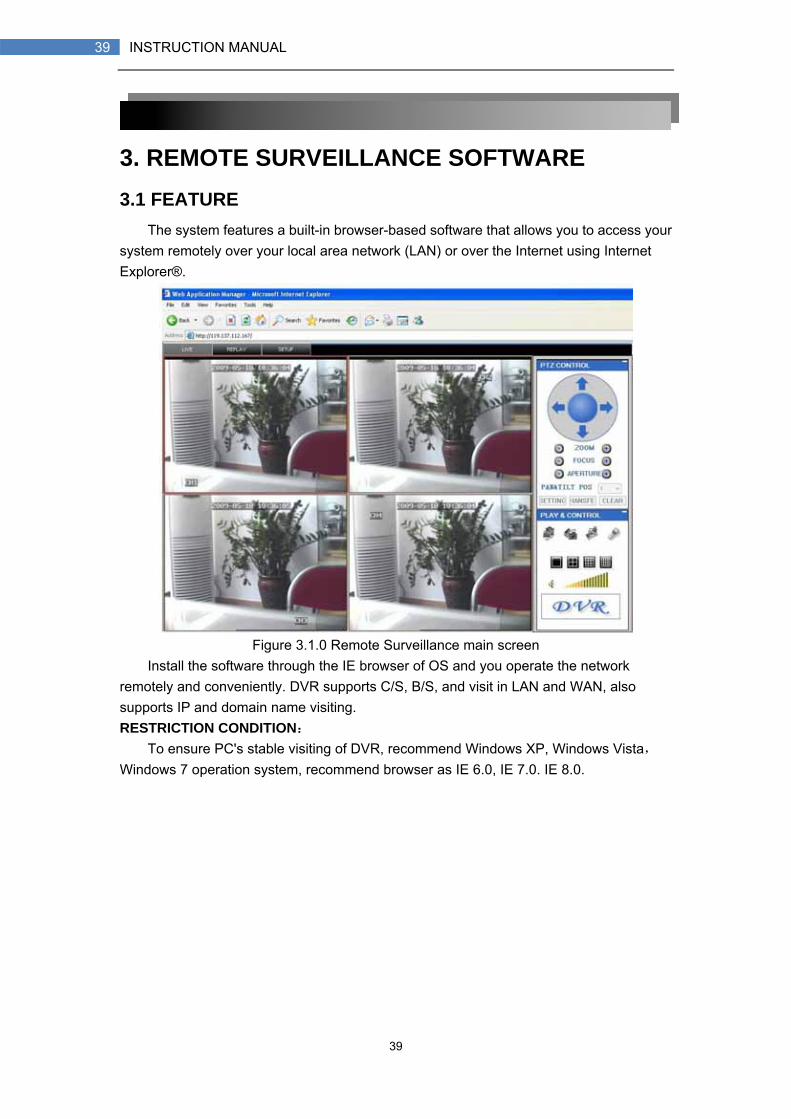
The system features a built-in browser-based software that allows you to access your system remotely over your local area network (LAN) or over the Internet using Internet Explorer®.
Figure 3.1.0 Remote Surveillance main screen
Install the software through the IE browser of OS and you operate the network remotely and conveniently. DVR supports C/S, B/S, and visit in LAN and WAN, also supports IP and domain name visiting. RESTRICTION CONDITION:
To ensure PC's stable visiting of DVR, recommend Windows XP, Windows Vista,Windows 7 operation system, recommend browser as IE 6.0, IE 7.0. IE 8.0.

40
40 INSTRUCTION MANUAL
3.2 USING REMOTE SURVEILLANCE With your system connected to your local area network, you can now log in to your
system using Internet Explorer. NOTE: Your system must be connected to your local or wide area network before attempting remote access. Logging In to Your System
With your IP address, you can now log in to your system over your local or wide area network. NOTE: You must configure DDNS settings locally.
To access your system: 1) Open Internet Explorer. In the address bar, enter the IP address of your system
(i.e. 192.168.3.97). 2) You must install the ActiveX® in order to access your system. Click the attention
bar at the top of the main page and select Install ActiveX Control. DVR Net viewer will reset.
Figure 3.2.1 Click the ActiveX attention bar
3) In the warning box click Install. The login page appears. 4) Leave the password field blank (default).
NOTE: If you have enabled passwords on your system, enter your USER or ADMIN password. However, only the ADMIN can change settings and options on the system.
5) Select LAN or INTERNET from the drop-down menu and click LOGIN. The process will last for 1~2 minutes.
Figure 3.2.2 Remote access login screen
41
41 INSTRUCTION MANUAL
3.3 REMOTE SURVEILLANCE MAIN SCREEN Upon login, the Remote Surveillance main screen appears in your browser.
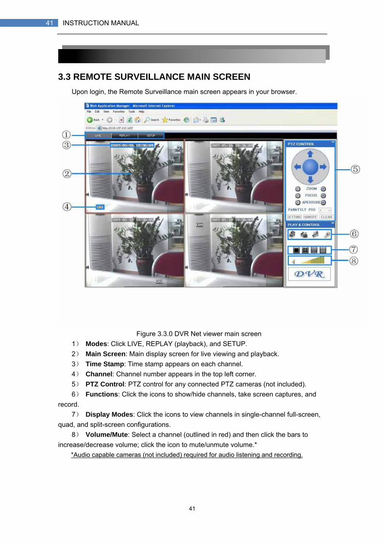
Figure 3.3.0 DVR Net viewer main screen
1) Modes: Click LIVE, REPLAY (playback), and SETUP. 2) Main Screen: Main display screen for live viewing and playback. 3) Time Stamp: Time stamp appears on each channel. 4) Channel: Channel number appears in the top left corner. 5) PTZ Control: PTZ control for any connected PTZ cameras (not included). 6) Functions: Click the icons to show/hide channels, take screen captures, and
record. 7) Display Modes: Click the icons to view channels in single-channel full-screen,
quad, and split-screen configurations. 8) Volume/Mute: Select a channel (outlined in red) and then click the bars to
increase/decrease volume; click the icon to mute/unmute volume.* *Audio capable cameras (not included) required for audio listening and recording.
42
42 INSTRUCTION MANUAL
3.3.1 LIVE VIEWING
By default, remote surveillance opens in Live Viewing mode (split-screen). To use Live Viewing:
1) Click LIVE at the top of the main screen. 2) Click the display mode icons to view the main screen in single-channel, quad, or
split-screen configurations. You can also double-click a channel at any time to view it in single-channel.
3) Click to show or hide all the channel windows.
4) Click to start/stop manual recording to your PC on ALL channels. For more
details see RECORDING. 5) Select a channel (outlined in red) and then click the audio bars to increase or
decrease listen-in volume. Click the icon to mute/unmute. NOTE: The Talk function is not supported. *Audio capable camera (not included) required for listen-in audio.
3.3.1.1 RECORDING
You can record video directly to your PC using the remote surveillance software. To record video to your PC:
From Live viewing, click to start/stop manual recording to your PC on ALL channels NOTE: You will record video to your PC regardless of the recording mode on the system itself. By default, recorded files are saved in C:\DVR\[ip_address]\Record.
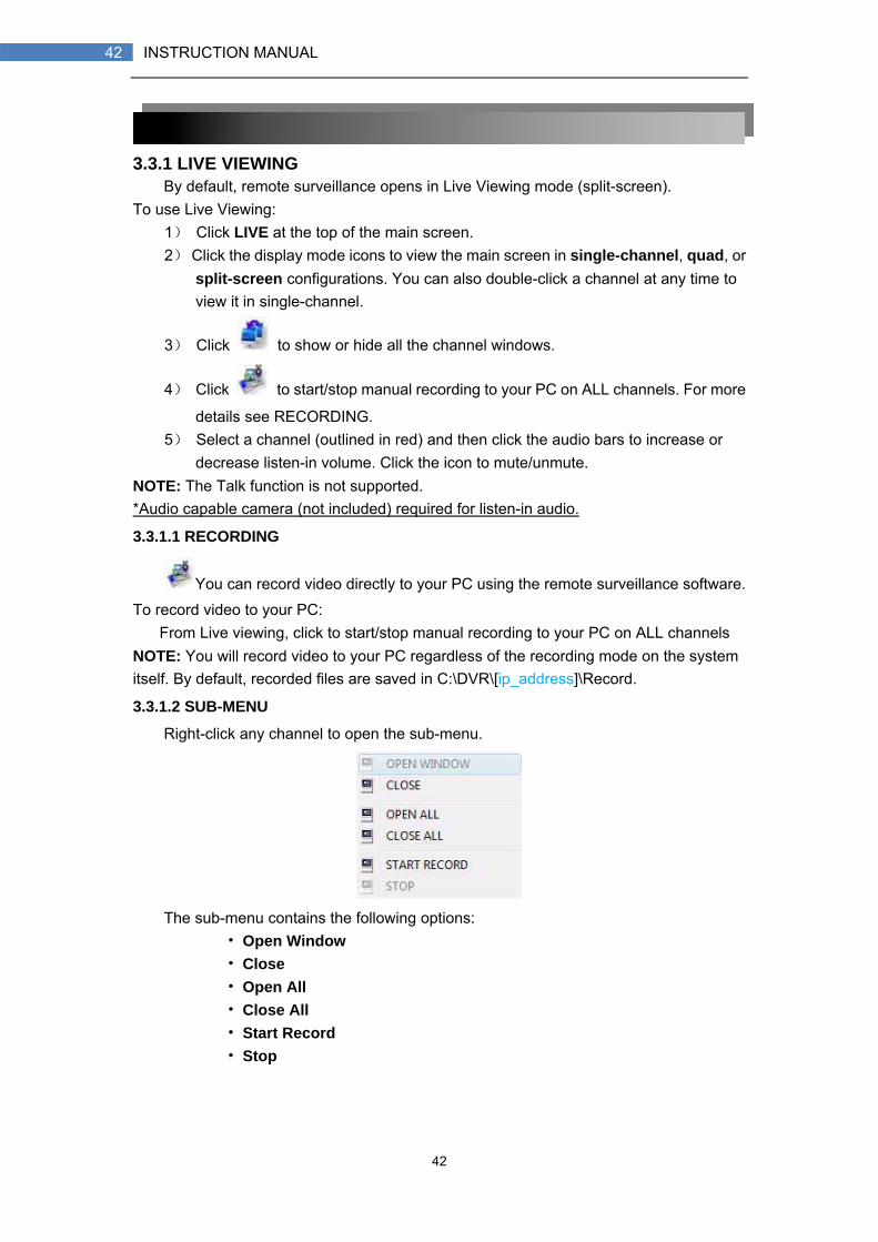
3.3.1.2 SUB-MENU
Right-click any channel to open the sub-menu.
The sub-menu contains the following options:
• Open Window • Close • Open All • Close All • Start Record • Stop

43
43 INSTRUCTION MANUAL
3.3.1.3 PTZ CONTROL
You must have a PTZ camera (not included) connected to the system in order to use the PTZ controls.
To control a PTZ camera: 1. Select the channel of the connected PTZ camera(s). 2. Click the navigation arrows to pan and tilt the camera. 3. Click + /- to control
zoom, focus, and iris. 4. Enter presets. 5. Click SETTING, HAND, and CLEAR to further control presets.
3.3.1.4 SCREEN CAPTURES
Use the remote surveillance software to take a snapshot of the channels on the main display screen. Screen Captures can be useful for your own records, or may be needed by authorities in case of a security incident. To take a screen capture:
1) From Live Viewing, select the channel you want to capture. The selected channel will be highlighted in a red frame.
2) Click .
3) Click OK in the confirmation window. Screen captures are saved as BMP files to the default save location (C:\DVR\...).
44
44 INSTRUCTION MANUAL
3.3.1.5 PLAYBACK
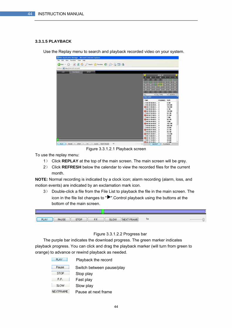
Use the Replay menu to search and playback recorded video on your system.
Figure 3.3.1.2.1 Playback screen
To use the replay menu: 1) Click REPLAY at the top of the main screen. The main screen will be grey. 2) Click REFRESH below the calendar to view the recorded files for the current
month. NOTE: Normal recording is indicated by a clock icon; alarm recording (alarm, loss, and motion events) are indicated by an exclamation mark icon.
3) Double-click a file from the File List to playback the file in the main screen. The icon in the file list changes to " ".Control playback using the buttons at the bottom of the main screen.
Figure 3.3.1.2.2 Progress bar
The purple bar indicates the download progress. The green marker indicates playback progress. You can click and drag the playback marker (will turn from green to orange) to advance or rewind playback as needed.
Playback the record
Switch between pause/play Stop play Fast play Slow play Pause at next frame
45
45 INSTRUCTION MANUAL
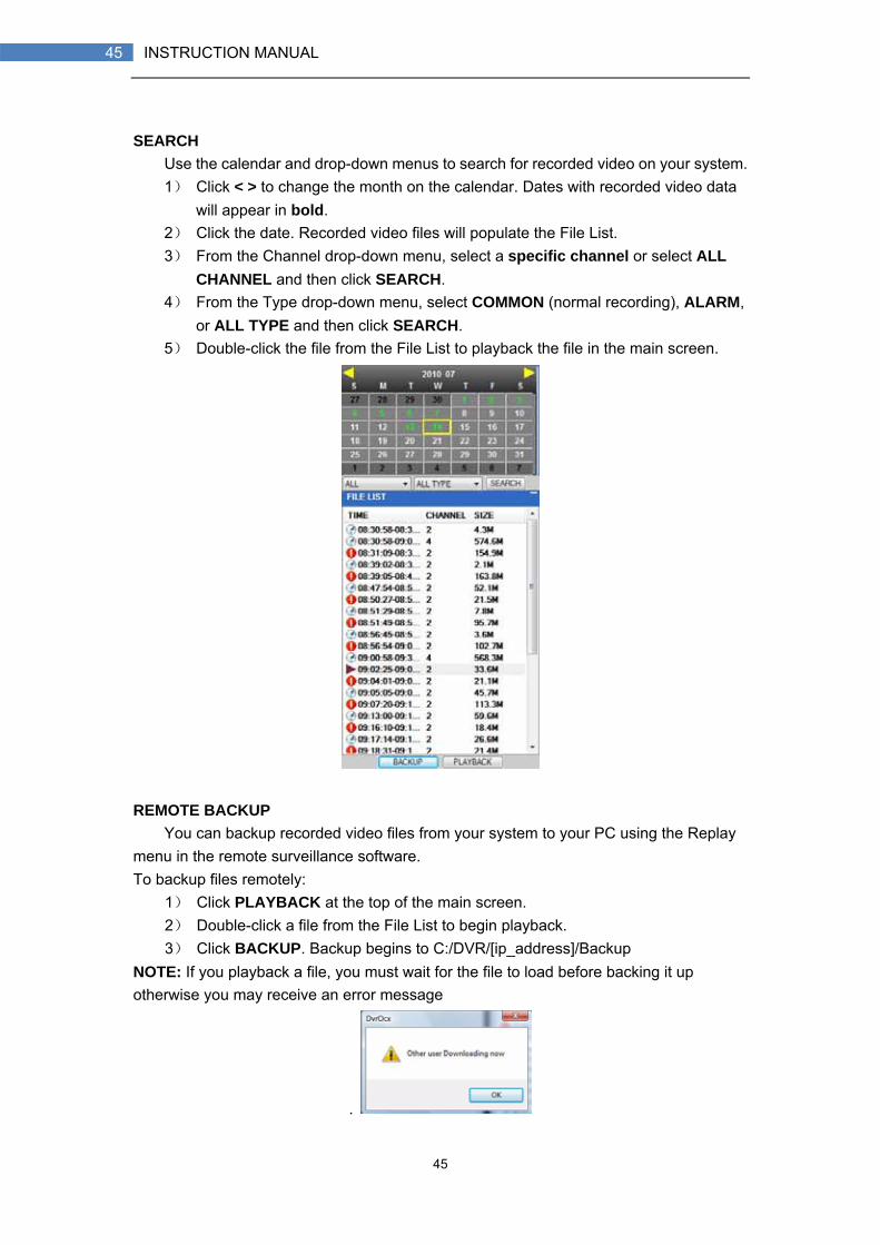
SEARCH
Use the calendar and drop-down menus to search for recorded video on your system. 1) Click < > to change the month on the calendar. Dates with recorded video data
will appear in bold. 2) Click the date. Recorded video files will populate the File List. 3) From the Channel drop-down menu, select a specific channel or select ALL
CHANNEL and then click SEARCH. 4) From the Type drop-down menu, select COMMON (normal recording), ALARM,
or ALL TYPE and then click SEARCH. 5) Double-click the file from the File List to playback the file in the main screen.
REMOTE BACKUP
You can backup recorded video files from your system to your PC using the Replay menu in the remote surveillance software. To backup files remotely:
1) Click PLAYBACK at the top of the main screen. 2) Double-click a file from the File List to begin playback. 3) Click BACKUP. Backup begins to C:/DVR/[ip_address]/Backup
NOTE: If you playback a file, you must wait for the file to load before backing it up otherwise you may receive an error message
.

46
46 INSTRUCTION MANUAL
5) When file backup is complete, click OK in the confirmation window. The confirmation window show the save path of the backup file.
NOTE: Backup files are saved as .264 files.
NOTE: Use the Player Software included on the software CD to playback backed up video.
47
47 INSTRUCTION MANUAL
3.3.3 REMOTE SETUP
Use the Setup tab to configure the settings of your system from a remote location. NOTE: If the Main Menu is open on the system, you will not be able to make changes
to the system from the remote location. To open remote setup:
Click SETUP at the top of the main screen. The Remote Setup menu features the following tabbed options:
• RECORD • ALARM • PTZ • NETWORK • SETTING • MAINTENANCE • HOST INFO
Click to enter into setup interface, this interface include record,
alarm, PTZ, network, setting and system information six menus.
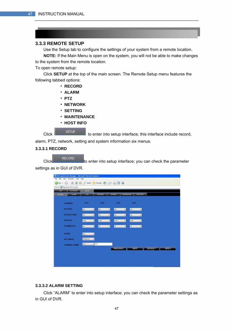
3.3.3.1 RECORD
Click to enter into setup interface; you can check the parameter settings as in GUI of DVR.
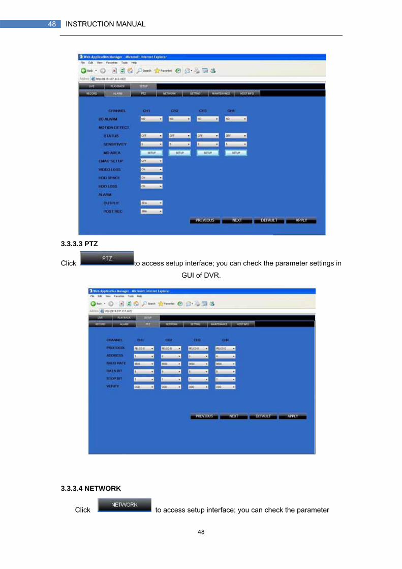
3.3.3.2 ALARM SETTING
Click “ALARM” to enter into setup interface; you can check the parameter settings as in GUI of DVR.
48
48 INSTRUCTION MANUAL
3.3.3.3 PTZ
Click to access setup interface; you can check the parameter settings in
GUI of DVR.
3.3.3.4 NETWORK
Click to access setup interface; you can check the parameter
49
49 INSTRUCTION MANUAL
settings in GUI of DVR.
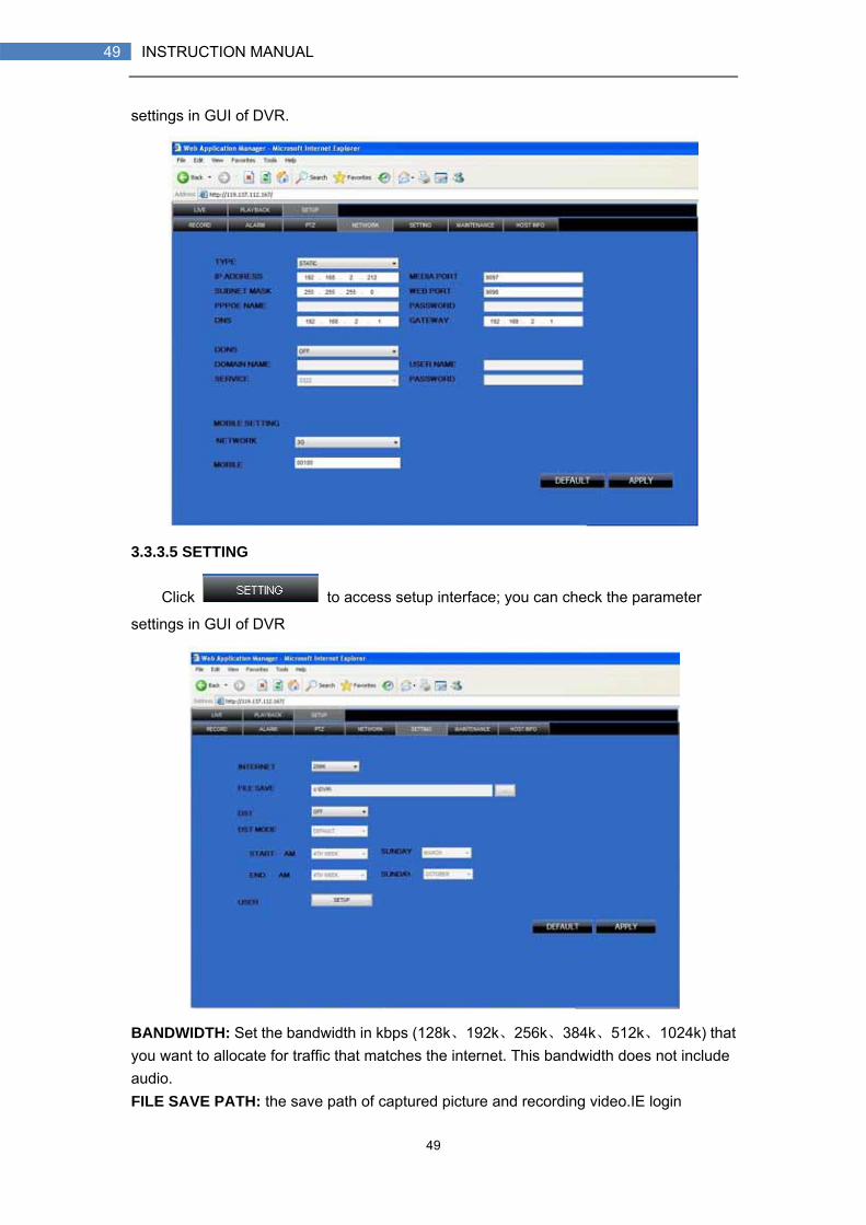
3.3.3.5 SETTING
Click to access setup interface; you can check the parameter
settings in GUI of DVR
BANDWIDTH: Set the bandwidth in kbps (128k、192k、256k、384k、512k、1024k) that you want to allocate for traffic that matches the internet. This bandwidth does not include audio. FILE SAVE PATH: the save path of captured picture and recording video.IE login
50
50 INSTRUCTION MANUAL
password and DST settings you can set as DVR setting.
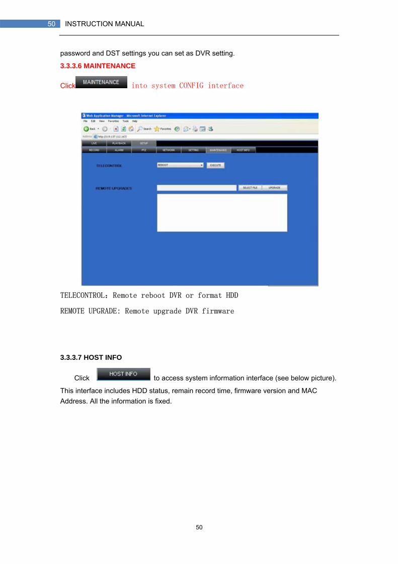
3.3.3.6 MAINTENANCE
Click into system CONFIG interface
TELECONTROL:Remote reboot DVR or format HDD
REMOTE UPGRADE: Remote upgrade DVR firmware
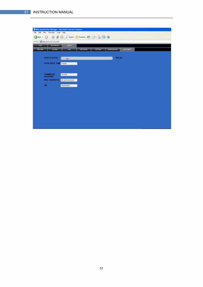
3.3.3.7 HOST INFO
Click to access system information interface (see below picture).
This interface includes HDD status, remain record time, firmware version and MAC Address. All the information is fixed.
51
51 INSTRUCTION MANUAL

52
52 INSTRUCTION MANUAL
4. DVR INSTALLATION GUIDELINE 4.1 FRONT PANEL 1. THE DEFINITION OF BOTTOMS AND CONNECTORS ON FRONT PANEL
1) Power: Press to power the system ON/OFF.
2) IR Sensor: IR receiver for the remote control.
3) LED Indicators: Shows status of HDD, recording, alarm, network, and power.
4) Channel/Numbers/Playback: Press buttons 1~4 (4-channel models) or 1~8 (8-channel models) to view the selected channel in full-screen; during playback, press the following:
• 6/ : Increase reverse playback speed 2X, 4X, 8X
• 7/ : Press to freeze playback to one frame, then press again to advance frame-by-frame
• 8/ : Press to start playback
• 9/ : Press to slow playback speed by 1/2, 1/4, 1/8
• 0/ : Press to increase forward playback speed 2X, 4X, 8X
5) MENU/EXIT: Press to open/close the main menu.
6) Navigation/OK: Press the Navigation buttons to perform the following:
• OK: In menus, press to confirm selections; in PTZ mode, press to change the navigation buttons to control the connected PTZ camera (not included)
• : Press to move cursor up; in PTZ mode, press to pan camera up
• : Press to move cursor down; in PTZ mode, press to pan camera down
• : Press to move cursor left; in PTZ mode, press to pan camera left
• : Press to move cursor right; in PTZ mode, press to pan camera right
7) USB: Connect a USB flash drive to the top port for data backup and firmware upgrades connect a USB mouse to the bottom port.

53
53 INSTRUCTION MANUAL
4.2 REAR PANEL 4-CHANNELS MODEL
Connectors on Rear Panel
Item Physical connector Connector description
1 POWER input DC 12V/3A
2 Audio Input For connecting audio signal
3 Video input For connecting analog video signal input (BNC)
4 Audio output For connection audio output
5 Video output One video output for connecting TV or monitor (BNC)
6 Network For connecting Ethernet
7 VGA output Optional
Alarm Input 4 I/O alarm input
Alarm Output I/O output for alarm
RS485 RS 485 for connecting PTZ
RS232 For connecting PC
8 Optional
+12V Power supply for DC relay and the current is 100MA (make OK short circuit can not happen)
54
54 INSTRUCTION MANUAL
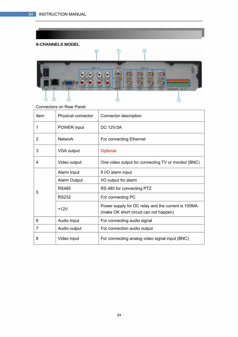
8-CHANNELS MODEL
Connectors on Rear Panel
Item Physical connector Connector description
1 POWER input DC 12V/3A
2 Network For connecting Ethernet
3 VGA output Optional
4 Video output One video output for connecting TV or monitor (BNC)
Alarm Input 8 I/O alarm input
Alarm Output I/O output for alarm
RS485 RS 485 for connecting PTZ
RS232 For connecting PC 5
+12V Power supply for DC relay and the current is 100MA (make OK short circuit can not happen)
6 Audio Input For connecting audio signal
7 Audio output For connection audio output
8 Video input For connecting analog video signal input (BNC)
55
55 INSTRUCTION MANUAL
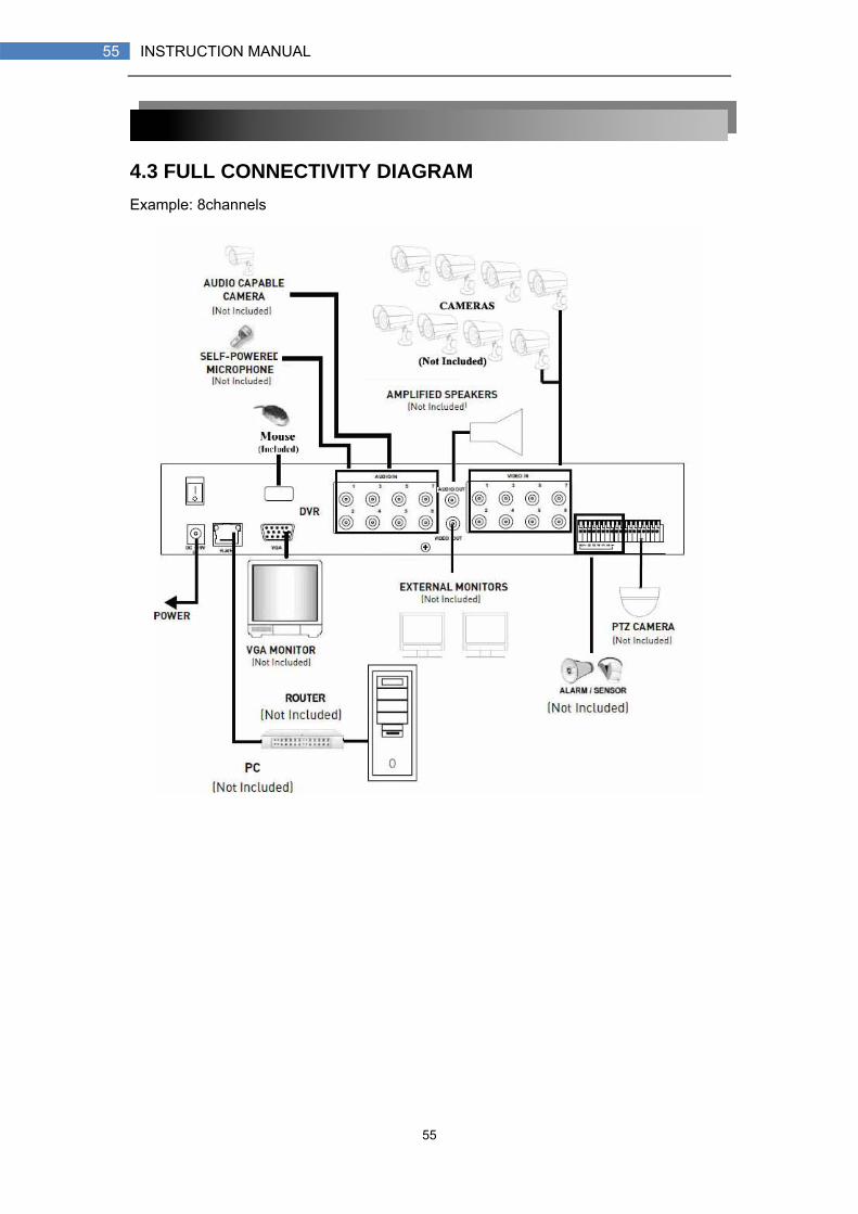
4.3 FULL CONNECTIVITY DIAGRAM Example: 8channels
56
56 INSTRUCTION MANUAL
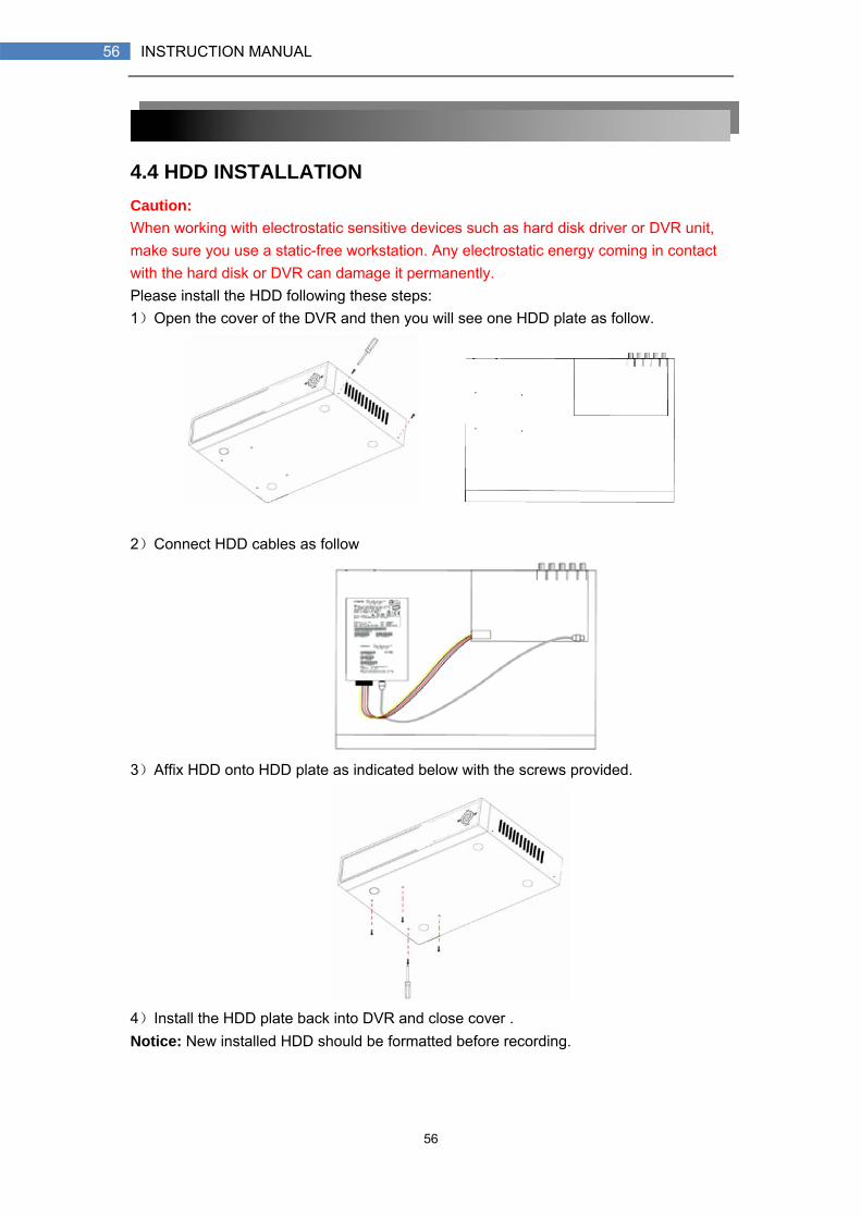
4.4 HDD INSTALLATION Caution: When working with electrostatic sensitive devices such as hard disk driver or DVR unit, make sure you use a static-free workstation. Any electrostatic energy coming in contact with the hard disk or DVR can damage it permanently. Please install the HDD following these steps: 1)Open the cover of the DVR and then you will see one HDD plate as follow.
2)Connect HDD cables as follow
3)Affix HDD onto HDD plate as indicated below with the screws provided.
4)Install the HDD plate back into DVR and close cover . Notice: New installed HDD should be formatted before recording.
57
57 INSTRUCTION MANUAL
5. FAQ If your problem is not listed below, please call our toll-free number for more support.
1. Question: DVR is not working after starting? Answer:
Check the adaptor input Check the on-off power line, is it well-connected? Check the power on-off Check the upgrade procedure Check the main board of DVR
2. Question: DVR is rebooting automatically or stopped after starting the DVR for several minutes? Answer:
Instability or low input voltage Bad track hard drive or the line of hard drive is bad On-off power supply is not enough The front-end video signal instability High temperature, too much dust, too bad the DVR operating environment The main board is not well-connected with other boards The hardware of DVR is defective
3. Question: No output of single channel, multi channel or all channel video? Answer:
Please check the adaptor of camera whether to see if it is well-connected Please check the cable for connecting video input/output in the back panel
of DVR Please insert the video source directly into the display device and check if
they are causing the problem. Check the brightness of the picture and bring it back to its original default
setting No video input signal or too weak Display settings in the preview set to be closed The hardware of DVR is defective
4. Question: DVR cannot record after startup and the interface is showing "H" Answer:
Make OK power adaptor is DC 19V Make OK HDD is formatted Check the power and data connection cables of the HDD The HDD is defective The SATA port is not working
5. Question: What is meaning of“R”“M”“I”“H” showed in interface? Answer:
“R”means the channel is recording

58
58 INSTRUCTION MANUAL
“M” means the channel is on motion detection “I”means the channel is on alarm “H” means there is either no HDD. the HDD is bad or the HDD is full
6. Question: DVR is having problem with real-time images, such as bad image color or serious brightness distortion Answer:
If PAL and NTSC is not correctly selected on the BNC output, the images will be in black and white
DVR is not compatible with monitor The video transmission distance is too far The setting of DVR color, brightness and so on are wrong
7. Question: No audio sound when monitoring? Answer:
Check sound box or speaker functions. Also check possible short circuit. Audio source may be connected to the video channel. You can click to
full-screen to check. The hardware of DVR is defective
8. Question: No audio sound when playing back? Answer:
Setting problem: open audio-video item Check the audio to see if it is closed in playback interface
9. Question: System time is not correct? Answer:
Wrong setting or user did not click "Edit" to confirm Battery is not connected properly Battery is dead. Please change.
10. Question: Why the “Stop recording” by the right mouse button does not work, how to stop recording? Answer:
The “Stop recording” by the right mouse button is only suitable for Manual recording. It can’t stop recording when it’s in “start recording” or the video in video plan.
If you want to stop recording, please set the time is not recording. 11. Question: "Stop recording" function by the right mouse button does not work.
How to stop recording? Answer: The "Stop recording" by the right mouse button is for Manual Recording only. It can
not stop recording when it is in "start recording" or the video is in video plan. If you want to stop recording, please set the time to not recoding. 12. Question: Motion detection is not working?
Answer: The setting of motion detection area is not correct Sensitivity is too low
13. Question: CD-writer /USB backup error

59
59 INSTRUCTION MANUAL
Answer: The data exceeds the capacity of backup device The backup device is incompatible The backup device is damaged
14. Question: Remote control cannot work? Answer:
The address of remote control is not correct The distance of remote control is too far or the angle is too biased Remote control batteries run out Remote control is damaged or the front panel of DVR is damaged
15. Question: WEB cannot login? Answer:
Please check the network to see if it is connected. Check if LINK or 100M LED is displayed normally on the panel; use ping xxx.xxx.xxx.xxx (DVR IP) to check if the Internet is linked properly.
Recommended to use Windows XP or Vista operating system, also use IE6.0 browser or IE7.0 browser
ActiveX control has been blocked. Please manually install ActiveX control again.
Please install DX8.1 and upgrade your video card driver 16. Question: There is no picture or picture is not clear when you preview the
recording or playback the recording via IE Answer:
If you access DVR by IE, please choose "Wan" in "web environment" Please try "Close windows" by the right mouse button, and try "Open
windows" again 17. Question: It displays "other members are setting......" while setting DVR by IE
Answer: It probably means someone else is setting the DVR. Please check the DVR
configuration interface or exit DVR.

60
60 INSTRUCTION MANUAL
TROUBLESHOOTING

61
61 INSTRUCTION MANUAL
Troubleshooting (cont`d.)